recent advances in muffler acoustics - iiav.org · recent advances in muffler acoustics m. l....
TRANSCRIPT

Recent Advances in Muffler AcousticsM. L. MunjalFacility for Research in Technical Acoustics (FRITA), Department of Mechanical Engineering, Indian Institute ofScience, Bangalore — 560 012, India.
(Received 23 December 2011; Accepted 14 November 2012)
Exhaust noise in engines has always been a major source of automotive noise. Challenges for muffler design havebeen constraints on size, back pressure, and, of course, the cost. Designing for sufficient insertion loss at theengine firing frequency and the first few harmonics has been the biggest challenge. Most advances in the designof efficient mufflers have resulted from linear plane wave theory, making use of the transfer matrix method. Thisreview paper deals with evaluating approximate source characteristics required for prediction of the unmuffledintake and exhaust noise, making use of the electroacoustical analogies. In the last few years, significant advanceshave been made in the analysis of variable area perforated ducts, transverse plane wave analysis of short elliptical aswell as circular chambers, double-tuned expansion chambers and concentric tube resonators, catalytic converters,diesel particulate filters, air cleaners, etc. The development of long strand fibrous materials that can be used inhot exhaust systems without binders has led to the use of combination mufflers in exhaust systems. Breakthroughshave been achieved in the prediction and control of breakout noise from the elliptical and circular muffler shell aswell as the end plates of typical mufflers. Diesel particulate filters and inlet air cleaners have also been modeledacoustically. Some of these recent advances are the subject of this review paper.
1. INTRODUCTION
Mufflers are essentially low-pass acoustical filters. Makinguse of electroacoustical analogies,1 lumped inductance and ca-pacitance of electrical wave filter are represented in mufflersby connecting pipes (or ducts) and chambers (or plenums),respectively. Helmholtz resonators of musical acoustics havealso found their counterpart here in the form of a hole-cavityresonator. Although the science of acoustics of ducts and muf-flers is over 150 years old,2 the first comprehensive experimen-tal investigation on analysis and design of mufflers for internalcombustion engines was reported by Davis et al. in 1954.3
The classical 1-D or plane wave theory with progressive wavesmoving in either direction led to the development of the trans-fer matrix method (TMM), which is ideally suited for acousti-cal modelling of cascaded elements constituting typical auto-motive mufflers.4
The TMM makes use of the standing wave variables to movefrom one element to the next in the cascade. Computationally,successive multiplication of transfer matrices is much faster aswell as more convenient than formulation and simultaneous so-lution of a large number of linear algebraic equations. In fact,a heuristic study of the transfer matrix multiplication processled to the development of a user-friendly algebraic algorithm,5
which in turn helped in a rational synthesis of 1-D acousticalfilters6 as well as vibration isolators.7
Morfey’s work on the sound generation and propagation inducts with mean flow8 indicated that the convective effect ofmean flow9 is to augment the flow-acoustical power of the for-ward wave and reduce that of the rearward (or reflected) wave.This led to the definition of convective (or flow acoustical) statevariables (pc, vc) that are linearly related in the classical (sta-tionary medium) state variables (p, v). Replacement of (p, v)with (pc, vc) yields identically similar expressions for inser-tion loss (IL) of a muffler with incompressible mean flow.10
The transformation relations between (p, v) and (pc, vc) enableconversion of the transfer matrices in classical state variableswith a moving medium to their counterparts in convective statevariables and vice versa.
A Helmholtz resonator introduces a sharp peak at its reso-nance frequency.10 However, designing an automotive mufflerrequires wide-band domes. Therefore, a designer would usepipes with extended perforations opening into an annular cav-ity. The resulting concentric tube resonator was first modelledby Sullivan and Crocker,11 making use of a 1-D control vol-ume approach. The resulting coupled equations were solved bywriting the acoustical field in the annular cylindrical cavity asa summation of natural modes satisfying the rigid-wall bound-ary conditions at the two ends. Sullivan followed it up witha segmentation approach which was applicable to a configu-ration with even three interacting ducts.12 Munjal, NarayanaRao, and Sahasrabudhe developed a generalized decouplingapproach for such perforated-element configurations.13, 14 Thisapproach was soon followed by Peat’s eigenvalue analysis,15
which was particularly tailored for digital computation, wherewe can make use of the standard subroutines or library func-tions. A parametric study by Munjal, Krishnan, and Reddyyielded a relative flow-acoustical performance of concentrictube resonators, plug mufflers, and chambers with three inter-acting ducts.16 Empirical expressions for the stagnation pres-sure drop for all three types of perforated-element muffler con-figurations were derived in terms of the open-area ratio of theperforate.16
Over the next decade, a large amount of research wasreported on acoustical analysis of complex perforated ele-ments,17–24 particularly the open-end flow-reversal elements24
and acoustical characterization of the exhaust and intake sys-tem of the reciprocating internal combustion engines.
Automobile engine is a variable speed engine, and therefore,a muffler must act as a low-pass filter with adequate wide-
International Journal of Acoustics and Vibration, Vol. 18, No. 2, 2013 (pp. 71–85) 71
M. L. Munjal: RECENT ADVANCES IN MUFFLER ACOUSTICS
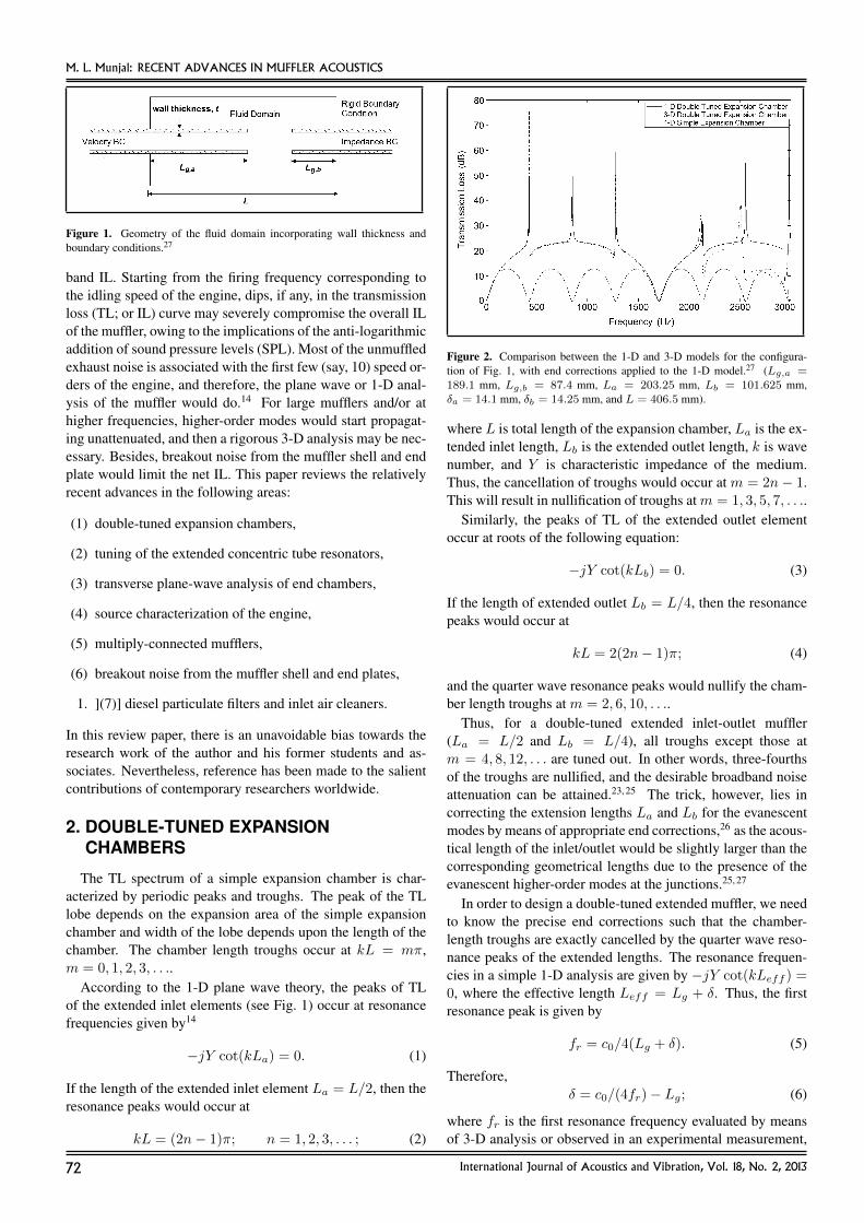
Figure 1. Geometry of the fluid domain incorporating wall thickness andboundary conditions.27
band IL. Starting from the firing frequency corresponding tothe idling speed of the engine, dips, if any, in the transmissionloss (TL; or IL) curve may severely compromise the overall ILof the muffler, owing to the implications of the anti-logarithmicaddition of sound pressure levels (SPL). Most of the unmuffledexhaust noise is associated with the first few (say, 10) speed or-ders of the engine, and therefore, the plane wave or 1-D anal-ysis of the muffler would do.14 For large mufflers and/or athigher frequencies, higher-order modes would start propagat-ing unattenuated, and then a rigorous 3-D analysis may be nec-essary. Besides, breakout noise from the muffler shell and endplate would limit the net IL. This paper reviews the relativelyrecent advances in the following areas:
(1) double-tuned expansion chambers,
(2) tuning of the extended concentric tube resonators,
(3) transverse plane-wave analysis of end chambers,
(4) source characterization of the engine,
(5) multiply-connected mufflers,
(6) breakout noise from the muffler shell and end plates,
1. ](7)] diesel particulate filters and inlet air cleaners.
In this review paper, there is an unavoidable bias towards theresearch work of the author and his former students and as-sociates. Nevertheless, reference has been made to the salientcontributions of contemporary researchers worldwide.
2. DOUBLE-TUNED EXPANSIONCHAMBERS
The TL spectrum of a simple expansion chamber is char-acterized by periodic peaks and troughs. The peak of the TLlobe depends on the expansion area of the simple expansionchamber and width of the lobe depends upon the length of thechamber. The chamber length troughs occur at kL = mπ,m = 0, 1, 2, 3, . . ..
According to the 1-D plane wave theory, the peaks of TLof the extended inlet elements (see Fig. 1) occur at resonancefrequencies given by14
−jY cot(kLa) = 0. (1)
If the length of the extended inlet element La = L/2, then theresonance peaks would occur at
kL = (2n− 1)π; n = 1, 2, 3, . . . ; (2)
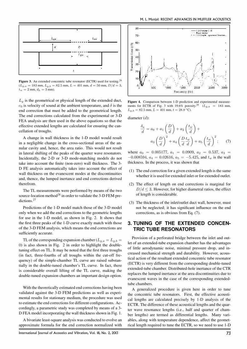
Figure 2. Comparison between the 1-D and 3-D models for the configura-tion of Fig. 1, with end corrections applied to the 1-D model.27 (Lg,a =189.1 mm, Lg,b = 87.4 mm, La = 203.25 mm, Lb = 101.625 mm,δa = 14.1 mm, δb = 14.25 mm, and L = 406.5 mm).
where L is total length of the expansion chamber, La is the ex-tended inlet length, Lb is the extended outlet length, k is wavenumber, and Y is characteristic impedance of the medium.Thus, the cancellation of troughs would occur at m = 2n− 1.This will result in nullification of troughs atm = 1, 3, 5, 7, . . ..
Similarly, the peaks of TL of the extended outlet elementoccur at roots of the following equation:
−jY cot(kLb) = 0. (3)
If the length of extended outlet Lb = L/4, then the resonancepeaks would occur at
kL = 2(2n− 1)π; (4)
and the quarter wave resonance peaks would nullify the cham-ber length troughs at m = 2, 6, 10, . . ..
Thus, for a double-tuned extended inlet-outlet muffler(La = L/2 and Lb = L/4), all troughs except those atm = 4, 8, 12, . . . are tuned out. In other words, three-fourthsof the troughs are nullified, and the desirable broadband noiseattenuation can be attained.23, 25 The trick, however, lies incorrecting the extension lengths La and Lb for the evanescentmodes by means of appropriate end corrections,26 as the acous-tical length of the inlet/outlet would be slightly larger than thecorresponding geometrical lengths due to the presence of theevanescent higher-order modes at the junctions.25, 27
In order to design a double-tuned extended muffler, we needto know the precise end corrections such that the chamber-length troughs are exactly cancelled by the quarter wave reso-nance peaks of the extended lengths. The resonance frequen-cies in a simple 1-D analysis are given by −jY cot(kLeff ) =0, where the effective length Leff = Lg + δ. Thus, the firstresonance peak is given by
fr = c0/4(Lg + δ). (5)
Therefore,δ = c0/(4fr)− Lg; (6)
where fr is the first resonance frequency evaluated by meansof 3-D analysis or observed in an experimental measurement,
72 International Journal of Acoustics and Vibration, Vol. 18, No. 2, 2013
M. L. Munjal: RECENT ADVANCES IN MUFFLER ACOUSTICS
Figure 3. An extended concentric tube resonator (ECTR) used for testing.29
(Lg,a = 183 mm, Lg,b = 82.5 mm, L = 401 mm, d = 50 mm, D/d = 3,tw = 2 mm, dh = 3 mm).
Lg is the geometrical or physical length of the extended duct,c0 is velocity of sound at the ambient temperature, and δ is theend correction that must be added to the geometrical length.The end corrections calculated from the experimental or 3-DFEA analysis are then used in the above equations so that theeffective extended lengths are calculated for ensuring the can-cellation of troughs.
A change in wall thickness in the 1-D model would resultin a negligible change in the cross-sectional areas of the an-nular cavity and, hence, the area ratio. This would not resultin lateral shifting of the peaks of the quarter wave resonators.Incidentally, the 2-D or 3-D mode-matching models do nottake into account the finite (non-zero) wall thickness. The 3-D FE analysis automatically takes into account the effect ofwall thickness on the evanescent modes at the discontinuitiesand, thence, the lumped inertance and end corrections derivedtherefrom.
The TL measurements were performed by means of the twosource-location method28 in order to validate the 3-D FEM pre-dictions.27
Predictions of the 1-D model match those of the 3-D modelonly when we add the end corrections to the geometric lengthsfor use in the 1-D model, as shown in Fig. 2. It shows thatthe first three peaks of the 1-D curve exactly match with thoseof the 3-D FEM analysis, which means the end corrections aresufficiently accurate.
TL of the corresponding expansion chamber (Lg,a = Lg,b =0) is also shown in Fig. 2 in order to highlight the double-tuning effect on TL. It may be noted that the first three troughs(in fact, three-fourths of all troughs within the cut-off fre-quency) of the simple-chamber TL curve are raised substan-tially in the double-tuned chamber’s TL curve. In fact, thereis considerable overall lifting of the TL curve, making thedouble-tuned expansion chambers an important design option.
With the theoretically estimated end corrections having beenvalidated against the 3-D FEM predictions as well as experi-mental results for stationary medium, the procedure was usedto estimate the end corrections for different configurations. Ac-cordingly, a parametric study was completed by means of a 3-D FEA model incorporating the wall thickness shown in Fig. 1.
A bivariate least-square analysis was conducted to evolve anapproximate formula for the end correction normalized with
Figure 4. Comparison between 1-D prediction and experimental measure-ments for ECTR of Fig. 3 with 19.6% porosity.29 (Lg,a = 183 mm,Lg,b = 82.5 mm, L = 401 mm, t = 28.8 ◦C).
diameter (d):
δad
= a0 + a1
(D
d
)+ a2
(twd
)+
a3
(D
d
)2
+ a4
(D
d
twd
)+ a5
(twd
)2
; (7)
where a0 = 0.005177, a1 = 0.0909, a2 = 0.537, a3 =−0.008594, a4 = 0.02616, a5 = −5.425, and tw is the wallthickness. In the process, it was shown that
(1) The end correction for a given extended length is the samewhether it is used for extended inlet or for extended outlet.
(2) The effect of length on end corrections is marginal forD/d ≤ 3. However, for higher diametral ratios, the effectof length is considerable.
(3) The thickness of the inlet/outlet duct wall, however, mustnot be neglected; it has significant influence on the endcorrections, as is obvious from Eq. (7).
3. TUNING OF THE EXTENDED CONCEN-TRIC TUBE RESONATORS
Provision of a perforated bridge between the inlet and out-let of an extended-tube expansion chamber has the advantagesof little aerodynamic noise, minimal pressure drop, and in-creased mechanical strength and durability. However, acous-tical action of the resultant extended concentric tube resonator(ECTR) is very different from the corresponding double-tunedextended-tube chamber. Distributed-hole inertance of the CTRreplaces the lumped inertance at the area discontinuities due toevanescent waves in the case of the corresponding extended-tube chambers.
A generalized procedure is given here in order to tunethe concentric tube resonators. First, the effective acousti-cal lengths are calculated precisely by 1-D analysis of theECTR. The difference of these acoustical lengths and the quar-ter wave resonance lengths (i.e., half and quarter of cham-ber lengths) are termed as differential lengths. Many vari-ables, along with temperature dependence, affect the geomet-rical length required to tune the ECTR, so we need to use 1-D
International Journal of Acoustics and Vibration, Vol. 18, No. 2, 2013 73

M. L. Munjal: RECENT ADVANCES IN MUFFLER ACOUSTICS
Figure 5. Double reversal end chamber muffler system.30
analysis to estimate the acoustical length and calculate the re-quired physical lengths from the differential lengths and endcorrections.
The differences between the two lengths (acoustical and ge-ometric) are referred to here as end corrections. These are aconsequence of the inertance of perforates.
The following least-squares fit has been developed for thedifferential length normalized with respect to the inner-tubediameter:29
∆
d= 4.522σ2 − 2.699σ + 0.6643; ∆ = ∆a = ∆b; (8)
where σ is porosity of the perforates (as a fraction). Equa-tion (8) is applicable for σ ranging from 0.1 to 0.27.
It is shown that an increase of the wall thickness by 0.5 mmor hole diameter by 1 mm increases the differential lengths by1 mm approximately. Differential lengths are calculated fromEq. (8) above for particular porosity and inner-tube diameter,and these are used to estimate the initial values of acousticallengths (La = L/2 − ∆, Lb = L/4 − ∆). With the helpof 1-D analysis, we can increase/decrease these lengths suchthat the chamber length troughs are nullified effectively. Theend corrections vary by –1.5 mm to +1.5 mm, and thus therequired geometric lengths are estimated (Lg,a = La − δa,Lg,b = Lb − δb).
Predictions of the 1-D model match with those observed ex-perimentally, and the end correction for this particular case isalmost zero, as shown in Fig. 4. In particular, the first threepeaks of the 1-D curve match exactly with experimental re-sults.
Thus, we can make use of the 1-D analysis along with pre-cise differential lengths and end corrections to tune the ex-tended concentric tube resonators so as to lift or tune out three-fourths of all troughs that characterize the TL curve of the cor-responding simple expansion chamber muffler. This makes thetuned ECTR a viable design option.
4. TRANSVERSE PLANE-WAVE ANALYSISOF END CHAMBERS
Elliptical end chambers form the basis of modern-day si-lencing systems in automobiles. In fact, one of the present dayautomotive silencing systems would consist of two such end
chambers connected by a uniform pipe, making use of double-flow reversal and inducing maximum impedance mismatch andthereby ensuring compactness of the design. Such a systemis shown in Fig. 5, wherein the end chambers (numbered 1and 3) and connecting pipes which also act as pass tubes areclearly shown. The lengths Lc of the connecting pipes aremuch greater than the lengths of the elliptical end chambersLa.
Rather than the time-consuming FEM process, which in-volves geometry creation, fine meshing (requiring a lot of com-puter memory, especially at higher frequencies), and solvinglinear systems with matrix inversion routines, a simple 1-Dmodel has been developed.
This 1-D transverse plane-wave approach can be used toobtain a transfer matrix, which is needed to cascade the ma-trix with the preceding and succeeding elements constituting acomplex muffler. The direction of the transverse plane wave istaken along the major axis of the ellipse with the cavities abovethe inlet and beneath the outlet modelled as variable area res-onators. The impedance of such a resonator is found using asemi-numeric technique called the matrizant approach.30 Thepath between the inlet and outlet ports is modelled as a 1-Dvariable area duct, and the matrizant method is applied to re-late the state variables at the downstream and upstream points.This rather novel method is ideally suited to incorporate thedissipative effect of mean flow at the junctions (sudden areadiscontinuities) of the end chamber.
Recently, this semi-analytical method has been replacedwith an analytical method. The Frobenius solution of the dif-ferential equation governing the transverse plane-wave propa-gation is obtained.31 By taking a sufficient number of termsof the infinite series, an approximate analytical solution soobtained shows good convergence up to about 1300 Hz andalso covers most of the range of muffler dimensions used inpractice. The TL performance of the muffler configurationscomputed by this analytical approach agrees excellently withthat computed by the matrizant approach,30 thereby offering afaster and more elegant alternate method to analyse short ellip-tical muffler configurations.
The perturbed continuity and momentum equations for aduct of a gradually varying cross-sectional area (S(x), alongthe axis of plane-wave propagation) with the isentropic condi-tion and assumption of time harmonic nature of the acoustical
74 International Journal of Acoustics and Vibration, Vol. 18, No. 2, 2013
M. L. Munjal: RECENT ADVANCES IN MUFFLER ACOUSTICS
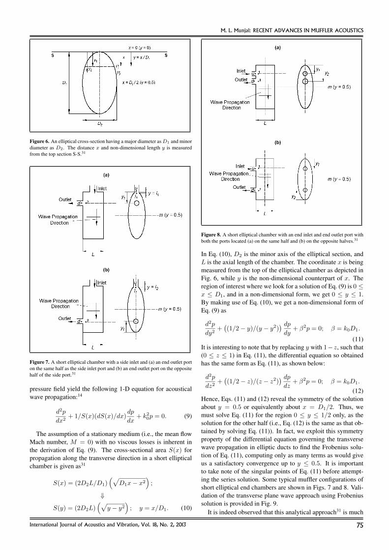
Figure 6. An elliptical cross-section having a major diameter asD1 and minordiameter as D2. The distance x and non-dimensional length y is measuredfrom the top section S-S.31
Figure 7. A short elliptical chamber with a side inlet and (a) an end outlet porton the same half as the side inlet port and (b) an end outlet port on the oppositehalf of the side port.31
pressure field yield the following 1-D equation for acousticalwave propagation:14
d2p
dx2+ 1/S(x)(dS(x)/dx)
dp
dx+ k20p = 0. (9)
The assumption of a stationary medium (i.e., the mean flowMach number, M = 0) with no viscous losses is inherent inthe derivation of Eq. (9). The cross-sectional area S(x) forpropagation along the transverse direction in a short ellipticalchamber is given as31
S(x) = (2D2L/D1)(√
D1x− x2)
;
⇓
S(y) = (2D2L)(√
y − y2)
; y = x/D1. (10)
Figure 8. A short elliptical chamber with an end inlet and end outlet port withboth the ports located (a) on the same half and (b) on the opposite halves.31
In Eq. (10), D2 is the minor axis of the elliptical section, andL is the axial length of the chamber. The coordinate x is beingmeasured from the top of the elliptical chamber as depicted inFig. 6, while y is the non-dimensional counterpart of x. Theregion of interest where we look for a solution of Eq. (9) is 0 ≤x ≤ D1, and in a non-dimensional form, we get 0 ≤ y ≤ 1.By making use of Eq. (10), we get a non-dimensional form ofEq. (9) as
d2p
dy2+((1/2− y)/(y − y2)
) dpdy
+ β2p = 0; β = k0D1.
(11)It is interesting to note that by replacing y with 1−z, such that(0 ≤ z ≤ 1) in Eq. (11), the differential equation so obtainedhas the same form as Eq. (11), as shown below:
d2p
dz2+((1/2− z)/(z − z2)
) dpdz
+ β2p = 0; β = k0D1.
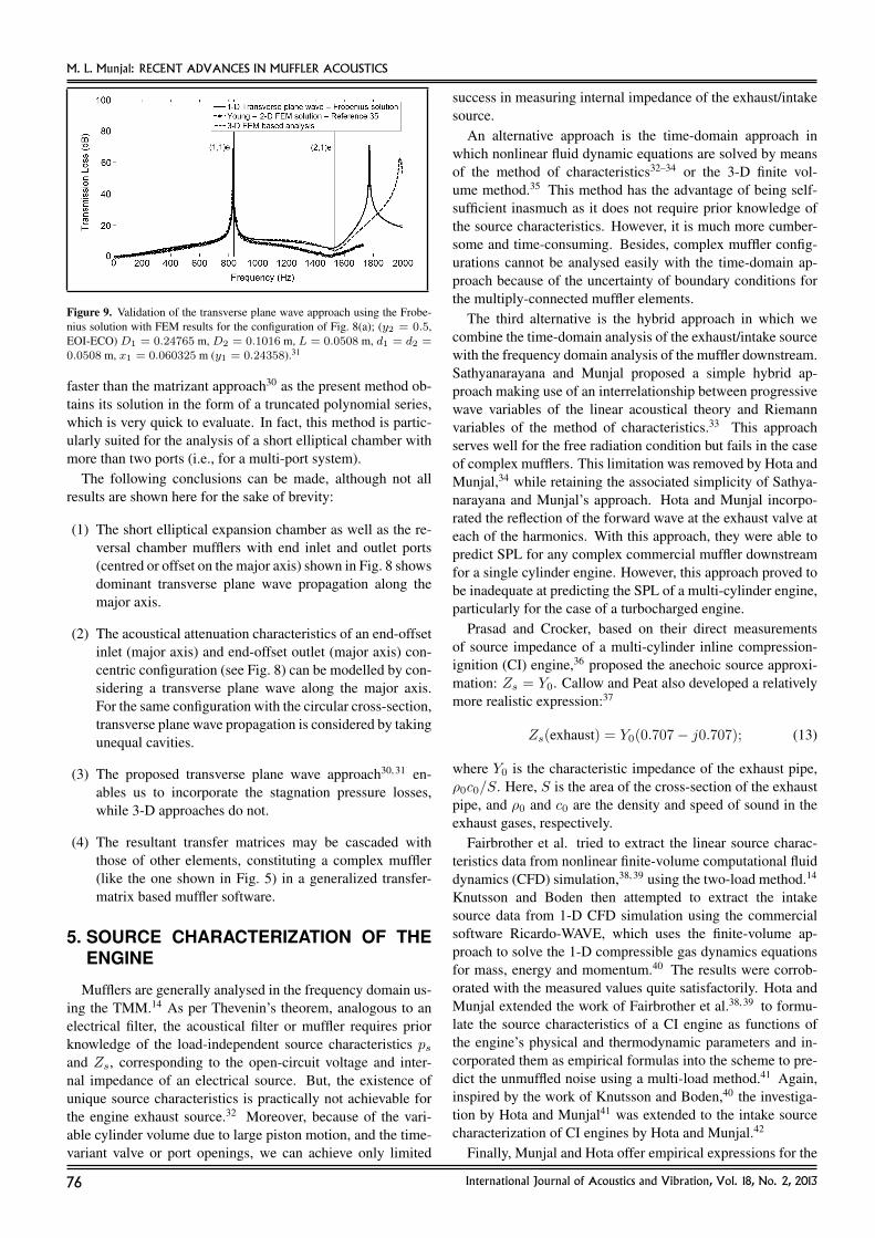
(12)Hence, Eqs. (11) and (12) reveal the symmetry of the solutionabout y = 0.5 or equivalently about x = D1/2. Thus, wemust solve Eq. (11) for the region 0 ≤ y ≤ 1/2 only, as thesolution for the other half (i.e., Eq. (12) is the same as that ob-tained by solving Eq. (11)). In fact, we exploit this symmetryproperty of the differential equation governing the transversewave propagation in elliptic ducts to find the Frobenius solu-tion of Eq. (11), computing only as many terms as would giveus a satisfactory convergence up to y ≤ 0.5. It is importantto take note of the singular points of Eq. (11) before attempt-ing the series solution. Some typical muffler configurations ofshort elliptical end chambers are shown in Figs. 7 and 8. Vali-dation of the transverse plane wave approach using Frobeniussolution is provided in Fig. 9.
It is indeed observed that this analytical approach31 is much
International Journal of Acoustics and Vibration, Vol. 18, No. 2, 2013 75
M. L. Munjal: RECENT ADVANCES IN MUFFLER ACOUSTICS
Figure 9. Validation of the transverse plane wave approach using the Frobe-nius solution with FEM results for the configuration of Fig. 8(a); (y2 = 0.5,EOI-ECO) D1 = 0.24765 m, D2 = 0.1016 m, L = 0.0508 m, d1 = d2 =0.0508 m, x1 = 0.060325 m (y1 = 0.24358).31
faster than the matrizant approach30 as the present method ob-tains its solution in the form of a truncated polynomial series,which is very quick to evaluate. In fact, this method is partic-ularly suited for the analysis of a short elliptical chamber withmore than two ports (i.e., for a multi-port system).
The following conclusions can be made, although not allresults are shown here for the sake of brevity:
(1) The short elliptical expansion chamber as well as the re-versal chamber mufflers with end inlet and outlet ports(centred or offset on the major axis) shown in Fig. 8 showsdominant transverse plane wave propagation along themajor axis.
(2) The acoustical attenuation characteristics of an end-offsetinlet (major axis) and end-offset outlet (major axis) con-centric configuration (see Fig. 8) can be modelled by con-sidering a transverse plane wave along the major axis.For the same configuration with the circular cross-section,transverse plane wave propagation is considered by takingunequal cavities.
(3) The proposed transverse plane wave approach30, 31 en-ables us to incorporate the stagnation pressure losses,while 3-D approaches do not.
(4) The resultant transfer matrices may be cascaded withthose of other elements, constituting a complex muffler(like the one shown in Fig. 5) in a generalized transfer-matrix based muffler software.
5. SOURCE CHARACTERIZATION OF THEENGINE
Mufflers are generally analysed in the frequency domain us-ing the TMM.14 As per Thevenin’s theorem, analogous to anelectrical filter, the acoustical filter or muffler requires priorknowledge of the load-independent source characteristics psand Zs, corresponding to the open-circuit voltage and inter-nal impedance of an electrical source. But, the existence ofunique source characteristics is practically not achievable forthe engine exhaust source.32 Moreover, because of the vari-able cylinder volume due to large piston motion, and the time-variant valve or port openings, we can achieve only limited
success in measuring internal impedance of the exhaust/intakesource.
An alternative approach is the time-domain approach inwhich nonlinear fluid dynamic equations are solved by meansof the method of characteristics32–34 or the 3-D finite vol-ume method.35 This method has the advantage of being self-sufficient inasmuch as it does not require prior knowledge ofthe source characteristics. However, it is much more cumber-some and time-consuming. Besides, complex muffler config-urations cannot be analysed easily with the time-domain ap-proach because of the uncertainty of boundary conditions forthe multiply-connected muffler elements.
The third alternative is the hybrid approach in which wecombine the time-domain analysis of the exhaust/intake sourcewith the frequency domain analysis of the muffler downstream.Sathyanarayana and Munjal proposed a simple hybrid ap-proach making use of an interrelationship between progressivewave variables of the linear acoustical theory and Riemannvariables of the method of characteristics.33 This approachserves well for the free radiation condition but fails in the caseof complex mufflers. This limitation was removed by Hota andMunjal,34 while retaining the associated simplicity of Sathya-narayana and Munjal’s approach. Hota and Munjal incorpo-rated the reflection of the forward wave at the exhaust valve ateach of the harmonics. With this approach, they were able topredict SPL for any complex commercial muffler downstreamfor a single cylinder engine. However, this approach proved tobe inadequate at predicting the SPL of a multi-cylinder engine,particularly for the case of a turbocharged engine.
Prasad and Crocker, based on their direct measurementsof source impedance of a multi-cylinder inline compression-ignition (CI) engine,36 proposed the anechoic source approxi-mation: Zs = Y0. Callow and Peat also developed a relativelymore realistic expression:37
Zs(exhaust) = Y0(0.707− j0.707); (13)
where Y0 is the characteristic impedance of the exhaust pipe,ρ0c0/S. Here, S is the area of the cross-section of the exhaustpipe, and ρ0 and c0 are the density and speed of sound in theexhaust gases, respectively.
Fairbrother et al. tried to extract the linear source charac-teristics data from nonlinear finite-volume computational fluiddynamics (CFD) simulation,38, 39 using the two-load method.14
Knutsson and Boden then attempted to extract the intakesource data from 1-D CFD simulation using the commercialsoftware Ricardo-WAVE, which uses the finite-volume ap-proach to solve the 1-D compressible gas dynamics equationsfor mass, energy and momentum.40 The results were corrob-orated with the measured values quite satisfactorily. Hota andMunjal extended the work of Fairbrother et al.38, 39 to formu-late the source characteristics of a CI engine as functions ofthe engine’s physical and thermodynamic parameters and in-corporated them as empirical formulas into the scheme to pre-dict the unmuffled noise using a multi-load method.41 Again,inspired by the work of Knutsson and Boden,40 the investiga-tion by Hota and Munjal41 was extended to the intake sourcecharacterization of CI engines by Hota and Munjal.42
Finally, Munjal and Hota offer empirical expressions for the
76 International Journal of Acoustics and Vibration, Vol. 18, No. 2, 2013
M. L. Munjal: RECENT ADVANCES IN MUFFLER ACOUSTICS
Figure 10. Electrical analogous circuit for an unmuffled system.42
Figure 11. Electrical analogous circuit for a muffled system.42 [T] is thetransfer matrix of the system (filter/muffler).
source strength level (SSL) in decibels of SI engines for theintake as well as the exhaust system.43
A prerequisite for this investigation is to have realistic valuesof the pressure-time history. These were computed using thecommercial software AVL-BOOST44 for different acousticalloads. This finite-volume CFD model is used in conjunctionwith the two-load method to evaluate the source characteristicsat a point in the exhaust pipe just downstream of the exhaustmanifold. The resultant source characteristics are used with thetransfer matrix-based muffler program45 to predict the exhaustSPL of a naturally aspirated four-stroke petrol or gasoline en-gine. Thus, the designer will be able to compute the exhaustSPL with reasonable accuracy and thereby synthesize the re-quired muffler configuration of a spark ignition (or gasoline)engine as well as the compression ignition (or diesel) engine.
The engine exhaust or intake source can be characterizedin accordance with the electrical analogy as can be seen inFigs. 10 and 11 for the unmuffled and muffled system, respec-tively. Here, acoustical pressure p and volume velocity v areanalogous to voltage (or electromotive force) and current in theelectrical network theory, respectively.
As per the electrical analogous circuits of the unmuffledsystem depicted in Fig. 10, for two different acoustical loads(impedances) ZL1 and ZL2, we can write38
psZL1 − p1Zs = p1ZL1; (14)
andpsZL2 − p2Zs = p2ZL2. (15)
These two equations may be solved simultaneously to obtain
ps = p1p2ZL1 − ZL2
p2ZL1 − p1ZL2; (16)
andZs = ZL1ZL2
p1 − p2p2ZL1 − p1ZL2
. (17)
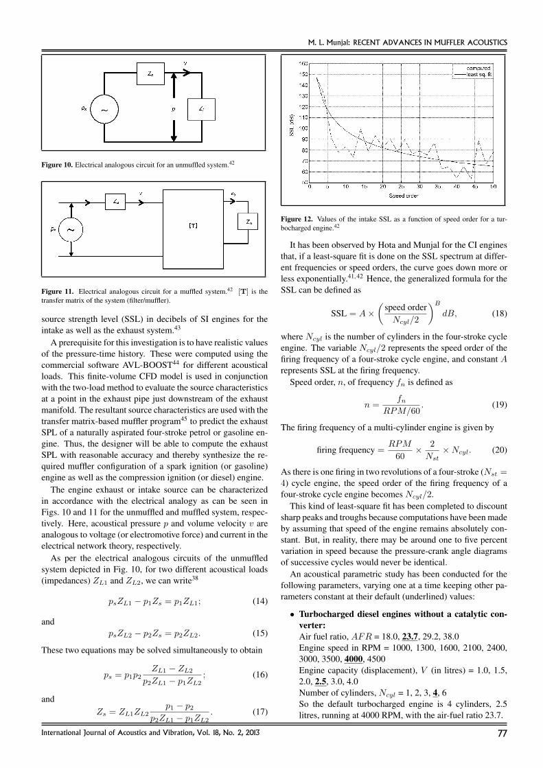
Figure 12. Values of the intake SSL as a function of speed order for a tur-bocharged engine.42
It has been observed by Hota and Munjal for the CI enginesthat, if a least-square fit is done on the SSL spectrum at differ-ent frequencies or speed orders, the curve goes down more orless exponentially.41, 42 Hence, the generalized formula for theSSL can be defined as
SSL = A×(
speed orderNcyl/2
)B
dB, (18)
where Ncyl is the number of cylinders in the four-stroke cycleengine. The variable Ncyl/2 represents the speed order of thefiring frequency of a four-stroke cycle engine, and constant Arepresents SSL at the firing frequency.
Speed order, n, of frequency fn is defined as
n =fn
RPM/60. (19)
The firing frequency of a multi-cylinder engine is given by
firing frequency =RPM
60× 2
Nst×Ncyl. (20)
As there is one firing in two revolutions of a four-stroke (Nst =4) cycle engine, the speed order of the firing frequency of afour-stroke cycle engine becomes Ncyl/2.
This kind of least-square fit has been completed to discountsharp peaks and troughs because computations have been madeby assuming that speed of the engine remains absolutely con-stant. But, in reality, there may be around one to five percentvariation in speed because the pressure-crank angle diagramsof successive cycles would never be identical.
An acoustical parametric study has been conducted for thefollowing parameters, varying one at a time keeping other pa-rameters constant at their default (underlined) values:
• Turbocharged diesel engines without a catalytic con-verter:Air fuel ratio, AFR = 18.0, 23.7, 29.2, 38.0Engine speed in RPM = 1000, 1300, 1600, 2100, 2400,3000, 3500, 4000, 4500Engine capacity (displacement), V (in litres) = 1.0, 1.5,2.0, 2.5, 3.0, 4.0Number of cylinders, Ncyl = 1, 2, 3, 4, 6So the default turbocharged engine is 4 cylinders, 2.5litres, running at 4000 RPM, with the air-fuel ratio 23.7.
International Journal of Acoustics and Vibration, Vol. 18, No. 2, 2013 77
M. L. Munjal: RECENT ADVANCES IN MUFFLER ACOUSTICS
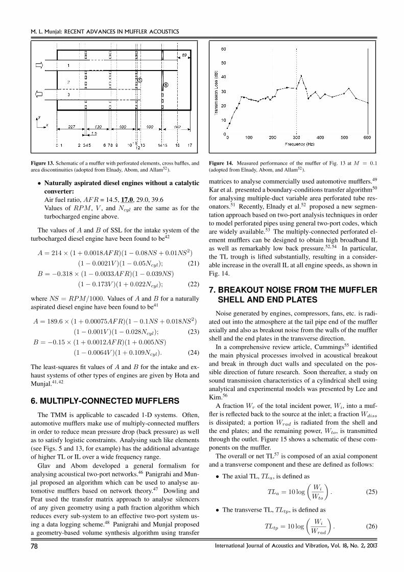
Figure 13. Schematic of a muffler with perforated elements, cross baffles, andarea discontinuities (adopted from Elnady, Abom, and Allam52).
• Naturally aspirated diesel engines without a catalyticconverter:Air fuel ratio, AFR = 14.5, 17.0, 29.0, 39.6Values of RPM , V , and Ncyl are the same as for theturbocharged engine above.
The values of A and B of SSL for the intake system of theturbocharged diesel engine have been found to be42
A = 214× (1 + 0.0018AFR)(1− 0.08NS + 0.01NS2)
(1− 0.0021V )(1− 0.05Ncyl); (21)
B = −0.318× (1− 0.0033AFR)(1− 0.039NS)
(1− 0.173V )(1 + 0.022Ncyl); (22)
where NS = RPM/1000. Values of A and B for a naturallyaspirated diesel engine have been found to be41
A = 189.6× (1 + 0.00075AFR)(1− 0.1NS + 0.018NS2)
(1− 0.001V )(1− 0.028Ncyl); (23)
B = −0.15× (1 + 0.0012AFR)(1 + 0.005NS)
(1− 0.0064V )(1 + 0.109Ncyl). (24)
The least-squares fit values of A and B for the intake and ex-haust systems of other types of engines are given by Hota andMunjal.41, 42
6. MULTIPLY-CONNECTED MUFFLERS
The TMM is applicable to cascaded 1-D systems. Often,automotive mufflers make use of multiply-connected mufflersin order to reduce mean pressure drop (back pressure) as wellas to satisfy logistic constraints. Analysing such like elements(see Figs. 5 and 13, for example) has the additional advantageof higher TL or IL over a wide frequency range.
Glav and Abom developed a general formalism foranalysing acoustical two-port networks.46 Panigrahi and Mun-jal proposed an algorithm which can be used to analyse au-tomotive mufflers based on network theory.47 Dowling andPeat used the transfer matrix approach to analyse silencersof any given geometry using a path fraction algorithm whichreduces every sub-system to an effective two-port system us-ing a data logging scheme.48 Panigrahi and Munjal proposeda geometry-based volume synthesis algorithm using transfer
Figure 14. Measured performance of the muffler of Fig. 13 at M = 0.1(adopted from Elnady, Abom, and Allam52).
matrices to analyse commercially used automotive mufflers.49
Kar et al. presented a boundary-conditions transfer algorithm50
for analysing multiple-duct variable area perforated tube res-onators.51 Recently, Elnady et al.52 proposed a new segmen-tation approach based on two-port analysis techniques in orderto model perforated pipes using general two-port codes, whichare widely available.53 The multiply-connected perforated el-ement mufflers can be designed to obtain high broadband ILas well as remarkably low back pressure.52, 54 In particular,the TL trough is lifted substantially, resulting in a consider-able increase in the overall IL at all engine speeds, as shown inFig. 14.
7. BREAKOUT NOISE FROM THE MUFFLERSHELL AND END PLATES
Noise generated by engines, compressors, fans, etc. is radi-ated out into the atmosphere at the tail pipe end of the muffleraxially and also as breakout noise from the walls of the mufflershell and the end plates in the transverse direction.
In a comprehensive review article, Cummings55 identifiedthe main physical processes involved in acoustical breakoutand break in through duct walls and speculated on the pos-sible direction of future research. Soon thereafter, a study onsound transmission characteristics of a cylindrical shell usinganalytical and experimental models was presented by Lee andKim.56
A fraction Wr of the total incident power, Wi, into a muf-fler is reflected back to the source at the inlet; a fraction Wdiss
is dissipated; a portion Wrad is radiated from the shell andthe end plates; and the remaining power, Wto, is transmittedthrough the outlet. Figure 15 shows a schematic of these com-ponents on the muffler.
The overall or net TL57 is composed of an axial componentand a transverse component and these are defined as follows:
• The axial TL, TLa, is defined as
TLa = 10 log
(Wi
Wto
). (25)
• The transverse TL, TLtp, is defined as
TLtp = 10 log
(Wi
Wrad
). (26)
78 International Journal of Acoustics and Vibration, Vol. 18, No. 2, 2013
M. L. Munjal: RECENT ADVANCES IN MUFFLER ACOUSTICS
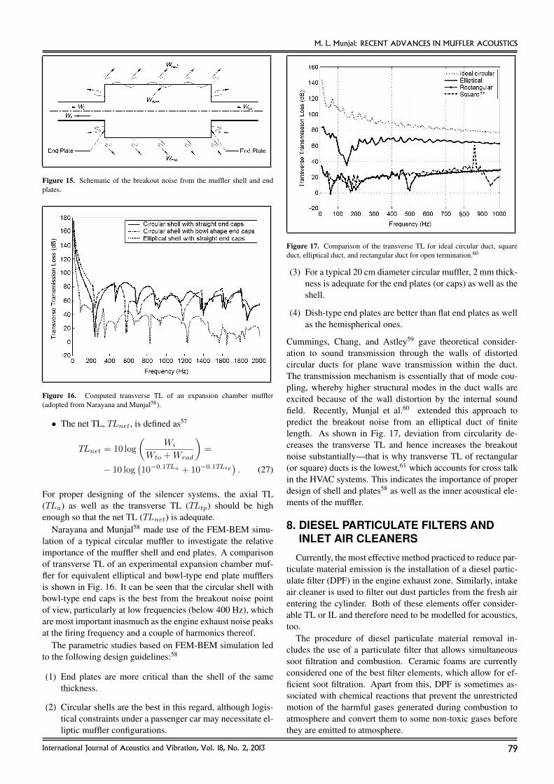
Figure 15. Schematic of the breakout noise from the muffler shell and endplates.
Figure 16. Computed transverse TL of an expansion chamber muffler(adopted from Narayana and Munjal58).
• The net TL, TLnet, is defined as57
TLnet = 10 log
(Wi
Wto +Wrad
)=
− 10 log(10−0.1TLa + 10−0.1TLtp
). (27)
For proper designing of the silencer systems, the axial TL(TLa) as well as the transverse TL (TLtp) should be highenough so that the net TL (TLnet) is adequate.
Narayana and Munjal58 made use of the FEM-BEM simu-lation of a typical circular muffler to investigate the relativeimportance of the muffler shell and end plates. A comparisonof transverse TL of an experimental expansion chamber muf-fler for equivalent elliptical and bowl-type end plate mufflersis shown in Fig. 16. It can be seen that the circular shell withbowl-type end caps is the best from the breakout noise pointof view, particularly at low frequencies (below 400 Hz), whichare most important inasmuch as the engine exhaust noise peaksat the firing frequency and a couple of harmonics thereof.
The parametric studies based on FEM-BEM simulation ledto the following design guidelines:58
(1) End plates are more critical than the shell of the samethickness.
(2) Circular shells are the best in this regard, although logis-tical constraints under a passenger car may necessitate el-liptic muffler configurations.
Figure 17. Comparison of the transverse TL for ideal circular duct, squareduct, elliptical duct, and rectangular duct for open termination.60
(3) For a typical 20 cm diameter circular muffler, 2 mm thick-ness is adequate for the end plates (or caps) as well as theshell.
(4) Dish-type end plates are better than flat end plates as wellas the hemispherical ones.
Cummings, Chang, and Astley59 gave theoretical consider-ation to sound transmission through the walls of distortedcircular ducts for plane wave transmission within the duct.The transmission mechanism is essentially that of mode cou-pling, whereby higher structural modes in the duct walls areexcited because of the wall distortion by the internal soundfield. Recently, Munjal et al.60 extended this approach topredict the breakout noise from an elliptical duct of finitelength. As shown in Fig. 17, deviation from circularity de-creases the transverse TL and hence increases the breakoutnoise substantially—that is why transverse TL of rectangular(or square) ducts is the lowest,61 which accounts for cross talkin the HVAC systems. This indicates the importance of properdesign of shell and plates58 as well as the inner acoustical ele-ments of the muffler.
8. DIESEL PARTICULATE FILTERS ANDINLET AIR CLEANERS
Currently, the most effective method practiced to reduce par-ticulate material emission is the installation of a diesel partic-ulate filter (DPF) in the engine exhaust zone. Similarly, intakeair cleaner is used to filter out dust particles from the fresh airentering the cylinder. Both of these elements offer consider-able TL or IL and therefore need to be modelled for acoustics,too.
The procedure of diesel particulate material removal in-cludes the use of a particulate filter that allows simultaneoussoot filtration and combustion. Ceramic foams are currentlyconsidered one of the best filter elements, which allow for ef-ficient soot filtration. Apart from this, DPF is sometimes as-sociated with chemical reactions that prevent the unrestrictedmotion of the harmful gases generated during combustion toatmosphere and convert them to some non-toxic gases beforethey are emitted to atmosphere.
International Journal of Acoustics and Vibration, Vol. 18, No. 2, 2013 79
M. L. Munjal: RECENT ADVANCES IN MUFFLER ACOUSTICS
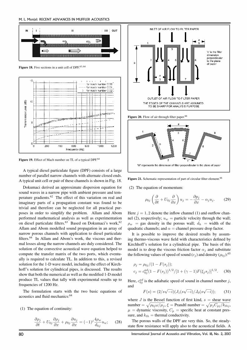
Figure 18. Five sections in a unit cell of DPF.63, 64
Figure 19. Effect of Mach number on TL of a typical DPF.64
A typical diesel particulate figure (DPF) consists of a largenumber of parallel narrow channels with alternate closed ends.A typical unit cell or pair of these channels is shown in Fig. 18.
Dokumaci derived an approximate dispersion equation forsound waves in a narrow pipe with ambient pressure and tem-perature gradients.62 The effect of this variation on real andimaginary parts of a propagation constant was found to betrivial and therefore can be neglected for all practical pur-poses in order to simplify the problem. Allam and Abomperformed mathematical analysis as well as experimentationon diesel particulate filters.63 Based on Dokumaci’s work,62
Allam and Abom modelled sound propagation in an array ofnarrow porous channels with application to diesel particulatefilters.64 In Allam and Abom’s work, the viscous and ther-mal losses along the narrow channels are duly considered. Thesolution of the convective acoustical wave equation helped tocompute the transfer matrix of the two ports, which eventu-ally is required to calculate TL. In addition to this, a revisedsolution for the 1-D wave model, including the effect of Kirch-hoff’s solution for cylindrical pipes, is discussed. The resultsshow that both the numerical as well as the modified 1-D modelproduce TL values that tally with experimental results up tofrequencies of 1200 Hz.
The formulation starts with the two basic equations ofacoustics and fluid mechanics:64
(1) The equation of continuity:
∂ρj∂t
+ U0j∂ρj∂x
+ ρ0j∂uj∂x
= (−1)j4ρwdhj
uw; (28)
Figure 20. Flow of air through filter paper.66
Figure 21. Schematic representation of part of circular filter element.66
(2) The equation of momentum:
ρ0j
(∂
∂t+ U0j
∂
∂x
)uj = −∂pj
∂x− αjuj . (29)
Here j = 1, 2 denote the inflow channel (1) and outflow chan-nel (2), respectively; uw = particle velocity through the wall;ρw = gas density in the porous wall; dh = width of thequadratic channels; and α = channel pressure drop factor.
It is possible to improve the desired results by assum-ing thermo-viscous wave field with characteristics defined byKirchhoff’s solution for a cylindrical pipe. The basis of thismodel is to drop the viscous friction factor αj and substitutethe following values of speed of sound (cj) and density (ρ0j):65
ρj = ρ0j/(1− F (sj));
cj = cad0j (1− F (sj))1/2/[1 + (γ − 1)F (ξjsj)]
1/2. (30)
Here, cad0j is the adiabatic speed of sound in channel number j,and
F (s) = (2/s√−i)(J1(s
√−i)/J0(s
√−i)); (31)
where J is the Bessel function of first kind, s = shear wavenumber =
√ρ0jω/µj , ξ = Prandtl number =
õjCpj/kthj ,
µ = dynamic viscosity, Cp = specific heat at constant pres-sure, and kth = thermal conductivity.
The porous walls of the DPF are very thin. So, the steady-state flow resistance will apply also to the acoustical fields. A
80 International Journal of Acoustics and Vibration, Vol. 18, No. 2, 2013
M. L. Munjal: RECENT ADVANCES IN MUFFLER ACOUSTICS
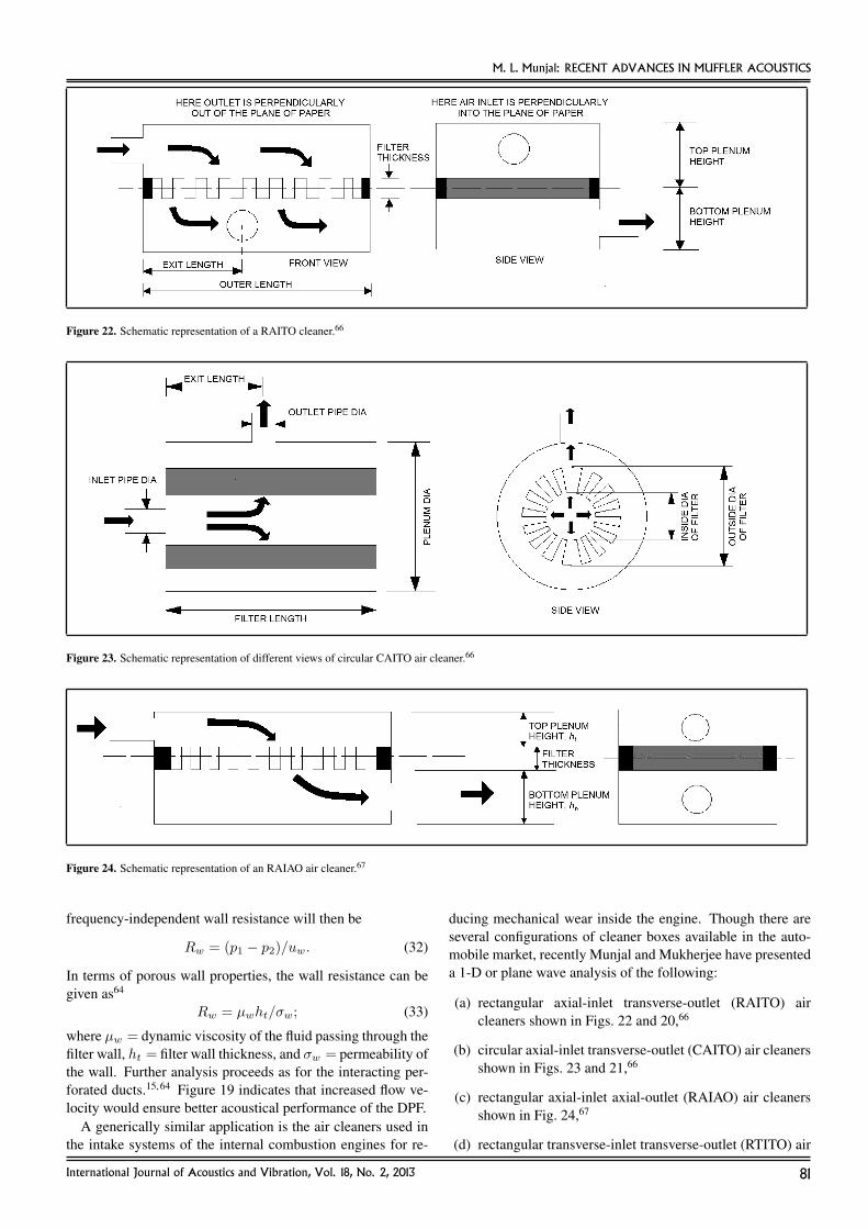
Figure 22. Schematic representation of a RAITO cleaner.66
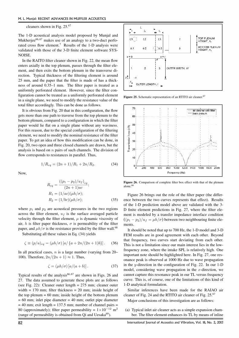
Figure 23. Schematic representation of different views of circular CAITO air cleaner.66
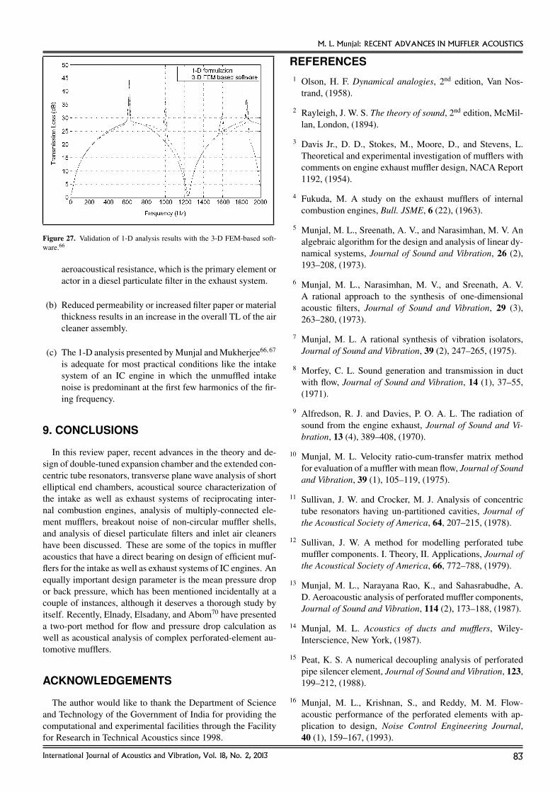
Figure 24. Schematic representation of an RAIAO air cleaner.67
frequency-independent wall resistance will then be
Rw = (p1 − p2)/uw. (32)
In terms of porous wall properties, the wall resistance can begiven as64
Rw = µwht/σw; (33)
where µw = dynamic viscosity of the fluid passing through thefilter wall, ht = filter wall thickness, and σw = permeability ofthe wall. Further analysis proceeds as for the interacting per-forated ducts.15, 64 Figure 19 indicates that increased flow ve-locity would ensure better acoustical performance of the DPF.
A generically similar application is the air cleaners used inthe intake systems of the internal combustion engines for re-
ducing mechanical wear inside the engine. Though there areseveral configurations of cleaner boxes available in the auto-mobile market, recently Munjal and Mukherjee have presenteda 1-D or plane wave analysis of the following:
(a) rectangular axial-inlet transverse-outlet (RAITO) aircleaners shown in Figs. 22 and 20,66
(b) circular axial-inlet transverse-outlet (CAITO) air cleanersshown in Figs. 23 and 21,66
(c) rectangular axial-inlet axial-outlet (RAIAO) air cleanersshown in Fig. 24,67
(d) rectangular transverse-inlet transverse-outlet (RTITO) air
International Journal of Acoustics and Vibration, Vol. 18, No. 2, 2013 81
M. L. Munjal: RECENT ADVANCES IN MUFFLER ACOUSTICS
cleaners shown in Fig. 25.67
The 1-D acoustical analysis model proposed by Munjal andMukherjee66, 67 makes use of an analogy to a two-duct perfo-rated cross flow element.7 Results of the 1-D analysis werevalidated with those of the 3-D finite element software SYS-NOISE.
In the RAITO filter cleaner shown in Fig. 22, the mean flowenters axially in the top plenum, passes through the filter ele-ment, and then exits the bottom plenum in the transverse di-rection. Typical thickness of the filtering element is around25 mm, and the paper that the filter is made of has a thick-ness of around 0.35–1 mm. The filter paper is treated as auniformly perforated element. However, since the filter con-figuration cannot be treated as a uniformly perforated elementin a single plane, we need to modify the resistance value of thetotal filter accordingly. This can be done as follows.
It is obvious from Fig. 20 that in this configuration, the flowgets more than one path to traverse from the top plenum to thebottom plenum, compared to a configuration in which the filterpaper would lie flat on a single plane without any waviness.For this reason, due to the special configuration of the filteringelement, we need to modify the nominal resistance of the filterpaper. To get an idea of how this modification can be done, inFig. 20, two open and three closed channels are drawn, but theanalysis is based on n pairs of such channels. The division offlow corresponds to resistances in parallel. Thus,
1/Req = (2n+ 1)/R1 + 2n/R2. (34)
Now,
Req =((p1 − p2)/uf )eq
(2n+ 1)ac;
R1 = (1/ac)(µh/σ);
R2 = (1/bc)(µh/σ); (35)
where p1 and p2 are acoustical pressures in the two regionsacross the filter element, uf is the surface averaged particlevelocity through the filter element, µ is dynamic viscosity ofair, h is filter paper thickness, σ is permeability of the filterpaper, and µh/σ is the resistance provided by the filter wall.68
Substituting all these values in Eq. (34) yields
ζ ≡ (p/u)eq = (µh/σ) [a/ {a+ 2n/(2n+ 1)b}] . (36)
In all practical cases, n is a large number (varying from 20–100). Therefore, 2n/(2n+ 1) ≈ 1. Thus,
ζ = (µh/σ) [a/(a+ b)] . (37)
Typical results of the analysis66, 67 are shown in Figs. 26 and27. The data assumed to generate these plots are as follows(see Fig. 22): Cleaner outer length = 275 mm; cleaner outerwidth = 170 mm; filter thickness = 20 mm; inside height ofthe top plenum = 60 mm; inside height of the bottom plenum= 60 mm; inlet pipe diameter = 40 mm; outlet pipe diameter= 40 mm; exit length = 137.5 mm; number of channel pairs =80 (approximately); filter paper permeability = 1×10⁻¹² m2
(range of permeability is obtained from Qi and Uesaka69).
Figure 25. Schematic representation of an RTITO air cleaner.67
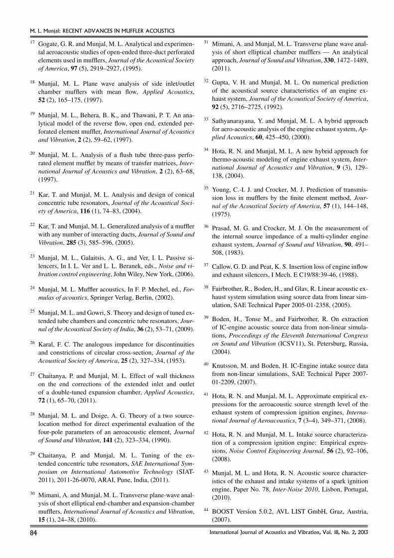
Figure 26. Comparison of complete filter box effect with that of the plenumalone.66
Figure 26 brings out the role of the filter paper (the differ-ence between the two curves represents that effect). Resultsof the 1-D prediction model above are validated with the 3-D finite element predictions in Fig. 27, where the filter ele-ment is modeled by a transfer impedance interface condition((p1 − p2)/uf = µh/σ) between two neighbouring finite ele-ments.
It should be noted that up to 700 Hz, the 1-D model and 3-DFEM results are in good agreement with each other. Beyondthat frequency, two curves start deviating from each other.This is not a limitation since our main interest lies in the low-frequency zone, where the intake SPL is relatively high. Oneimportant note should be highlighted here. In Fig. 27, one res-onance peak is observed at 1000 Hz due to wave propagationin the y-direction in the configuration of Fig. 22. In our 1-Dmodel, considering wave propagation in the x-direction, wecannot capture this resonance peak in our TL versus frequencycurve. This is, of course, one of the limitations of this kind of1-D analytical formulation.
Similar inferences have been made for the RAIAO aircleaner of Fig. 24 and the RTITO air cleaner of Fig. 25.67
Major conclusions of this investigation are as follows:
(a) Typical inlet air cleaner acts as a simple expansion cham-ber. The filter element enhances its TL by means of inline
82 International Journal of Acoustics and Vibration, Vol. 18, No. 2, 2013
M. L. Munjal: RECENT ADVANCES IN MUFFLER ACOUSTICS
Figure 27. Validation of 1-D analysis results with the 3-D FEM-based soft-ware.66
aeroacoustical resistance, which is the primary element oractor in a diesel particulate filter in the exhaust system.
(b) Reduced permeability or increased filter paper or materialthickness results in an increase in the overall TL of the aircleaner assembly.
(c) The 1-D analysis presented by Munjal and Mukherjee66, 67
is adequate for most practical conditions like the intakesystem of an IC engine in which the unmuffled intakenoise is predominant at the first few harmonics of the fir-ing frequency.
9. CONCLUSIONS
In this review paper, recent advances in the theory and de-sign of double-tuned expansion chamber and the extended con-centric tube resonators, transverse plane wave analysis of shortelliptical end chambers, acoustical source characterization ofthe intake as well as exhaust systems of reciprocating inter-nal combustion engines, analysis of multiply-connected ele-ment mufflers, breakout noise of non-circular muffler shells,and analysis of diesel particulate filters and inlet air cleanershave been discussed. These are some of the topics in muffleracoustics that have a direct bearing on design of efficient muf-flers for the intake as well as exhaust systems of IC engines. Anequally important design parameter is the mean pressure dropor back pressure, which has been mentioned incidentally at acouple of instances, although it deserves a thorough study byitself. Recently, Elnady, Elsadany, and Abom70 have presenteda two-port method for flow and pressure drop calculation aswell as acoustical analysis of complex perforated-element au-tomotive mufflers.
ACKNOWLEDGEMENTS
The author would like to thank the Department of Scienceand Technology of the Government of India for providing thecomputational and experimental facilities through the Facilityfor Research in Technical Acoustics since 1998.
REFERENCES1 Olson, H. F. Dynamical analogies, 2nd edition, Van Nos-
trand, (1958).
2 Rayleigh, J. W. S. The theory of sound, 2nd edition, McMil-lan, London, (1894).
3 Davis Jr., D. D., Stokes, M., Moore, D., and Stevens, L.Theoretical and experimental investigation of mufflers withcomments on engine exhaust muffler design, NACA Report1192, (1954).
4 Fukuda, M. A study on the exhaust mufflers of internalcombustion engines, Bull. JSME, 6 (22), (1963).
5 Munjal, M. L., Sreenath, A. V., and Narasimhan, M. V. Analgebraic algorithm for the design and analysis of linear dy-namical systems, Journal of Sound and Vibration, 26 (2),193–208, (1973).
6 Munjal, M. L., Narasimhan, M. V., and Sreenath, A. V.A rational approach to the synthesis of one-dimensionalacoustic filters, Journal of Sound and Vibration, 29 (3),263–280, (1973).
7 Munjal, M. L. A rational synthesis of vibration isolators,Journal of Sound and Vibration, 39 (2), 247–265, (1975).
8 Morfey, C. L. Sound generation and transmission in ductwith flow, Journal of Sound and Vibration, 14 (1), 37–55,(1971).
9 Alfredson, R. J. and Davies, P. O. A. L. The radiation ofsound from the engine exhaust, Journal of Sound and Vi-bration, 13 (4), 389–408, (1970).
10 Munjal, M. L. Velocity ratio-cum-transfer matrix methodfor evaluation of a muffler with mean flow, Journal of Soundand Vibration, 39 (1), 105–119, (1975).
11 Sullivan, J. W. and Crocker, M. J. Analysis of concentrictube resonators having un-partitioned cavities, Journal ofthe Acoustical Society of America, 64, 207–215, (1978).
12 Sullivan, J. W. A method for modelling perforated tubemuffler components. I. Theory, II. Applications, Journal ofthe Acoustical Society of America, 66, 772–788, (1979).
13 Munjal, M. L., Narayana Rao, K., and Sahasrabudhe, A.D. Aeroacoustic analysis of perforated muffler components,Journal of Sound and Vibration, 114 (2), 173–188, (1987).
14 Munjal, M. L. Acoustics of ducts and mufflers, Wiley-Interscience, New York, (1987).
15 Peat, K. S. A numerical decoupling analysis of perforatedpipe silencer element, Journal of Sound and Vibration, 123,199–212, (1988).
16 Munjal, M. L., Krishnan, S., and Reddy, M. M. Flow-acoustic performance of the perforated elements with ap-plication to design, Noise Control Engineering Journal,40 (1), 159–167, (1993).
International Journal of Acoustics and Vibration, Vol. 18, No. 2, 2013 83
M. L. Munjal: RECENT ADVANCES IN MUFFLER ACOUSTICS
17 Gogate, G. R. and Munjal, M. L. Analytical and experimen-tal aeroacoustic studies of open-ended three-duct perforatedelements used in mufflers, Journal of the Acoustical Societyof America, 97 (5), 2919–2927, (1995).
18 Munjal, M. L. Plane wave analysis of side inlet/outletchamber mufflers with mean flow, Applied Acoustics,52 (2), 165–175, (1997).
19 Munjal, M. L., Behera, B. K., and Thawani, P. T. An ana-lytical model of the reverse flow, open end, extended per-forated element muffler, International Journal of Acousticsand Vibration, 2 (2), 59–62, (1997).
20 Munjal, M. L. Analysis of a flush tube three-pass perfo-rated element muffler by means of transfer matrices, Inter-national Journal of Acoustics and Vibration, 2 (2), 63–68,(1997).
21 Kar, T. and Munjal, M. L. Analysis and design of conicalconcentric tube resonators, Journal of the Acoustical Soci-ety of America, 116 (1), 74–83, (2004).
22 Kar, T. and Munjal, M. L. Generalized analysis of a mufflerwith any number of interacting ducts, Journal of Sound andVibration, 285 (3), 585–596, (2005).
23 Munjal, M. L., Galaitsis, A. G., and Ver, I. L. Passive si-lencers, In I. L. Ver and L. L. Beranek, eds., Noise and vi-bration control engineering, John Wiley, New York, (2006).
24 Munjal, M. L. Muffler acoustics, In F. P. Mechel, ed., For-mulas of acoustics, Springer Verlag, Berlin, (2002).
25 Munjal, M. L. and Gowri, S. Theory and design of tuned ex-tended tube chambers and concentric tube resonators, Jour-nal of the Acoustical Society of India, 36 (2), 53–71, (2009).
26 Karal, F. C. The analogous impedance for discontinuitiesand constrictions of circular cross-section, Journal of theAcoustical Society of America, 25 (2), 327–334, (1953).
27 Chaitanya, P. and Munjal, M. L. Effect of wall thicknesson the end corrections of the extended inlet and outletof a double-tuned expansion chamber, Applied Acoustics,72 (1), 65–70, (2011).
28 Munjal, M. L. and Doige, A. G. Theory of a two source-location method for direct experimental evaluation of thefour-pole parameters of an aeroacoustic element, Journalof Sound and Vibration, 141 (2), 323–334, (1990).
29 Chaitanya, P. and Munjal, M. L. Tuning of the ex-tended concentric tube resonators, SAE International Sym-posium on International Automotive Technology (SIAT-2011), 2011-26-0070, ARAI, Pune, India, (2011).
30 Mimani, A. and Munjal, M. L. Transverse plane-wave anal-ysis of short elliptical end-chamber and expansion-chambermufflers, International Journal of Acoustics and Vibration,15 (1), 24–38, (2010).
31 Mimani, A. and Munjal, M. L. Transverse plane wave anal-ysis of short elliptical chamber mufflers — An analyticalapproach, Journal of Sound and Vibration, 330, 1472–1489,(2011).
32 Gupta, V. H. and Munjal, M. L. On numerical predictionof the acoustical source characteristics of an engine ex-haust system, Journal of the Acoustical Society of America,92 (5), 2716–2725, (1992).
33 Sathyanarayana, Y. and Munjal, M. L. A hybrid approachfor aero-acoustic analysis of the engine exhaust system, Ap-plied Acoustics, 60, 425–450, (2000).
34 Hota, R. N. and Munjal, M. L. A new hybrid approach forthermo-acoustic modeling of engine exhaust system, Inter-national Journal of Acoustics and Vibration, 9 (3), 129–138, (2004).
35 Young, C.-I. J. and Crocker, M. J. Prediction of transmis-sion loss in mufflers by the finite element method, Jour-nal of the Acoustical Society of America, 57 (1), 144–148,(1975).
36 Prasad, M. G. and Crocker, M. J. On the measurement ofthe internal source impedance of a multi-cylinder engineexhaust system, Journal of Sound and Vibration, 90, 491–508, (1983).
37 Callow, G. D. and Peat, K. S. Insertion loss of engine inflowand exhaust silencers, I Mech. E C19/88:39-46, (1988).
38 Fairbrother, R., Boden, H., and Glav, R. Linear acoustic ex-haust system simulation using source data from linear sim-ulation, SAE Technical Paper 2005-01-2358, (2005).
39 Boden, H., Tonse M., and Fairbrother, R. On extractionof IC-engine acoustic source data from non-linear simula-tions, Proceedings of the Eleventh International Congresson Sound and Vibration (ICSV11), St. Petersburg, Russia,(2004).
40 Knutsson, M. and Boden, H. IC-Engine intake source datafrom non-linear simulations, SAE Technical Paper 2007-01-2209, (2007).
41 Hota, R. N. and Munjal, M. L. Approximate empirical ex-pressions for the aeroacoustic source strength level of theexhaust system of compression ignition engines, Interna-tional Journal of Aeroacoustics, 7 (3–4), 349–371, (2008).
42 Hota, R. N. and Munjal, M. L. Intake source characteriza-tion of a compression ignition engine: Empirical expres-sions, Noise Control Engineering Journal, 56 (2), 92–106,(2008).
43 Munjal, M. L. and Hota, R. N. Acoustic source character-istics of the exhaust and intake systems of a spark ignitionengine, Paper No. 78, Inter-Noise 2010, Lisbon, Portugal,(2010).
44 BOOST Version 5.0.2, AVL LIST GmbH, Graz, Austria,(2007).
84 International Journal of Acoustics and Vibration, Vol. 18, No. 2, 2013
M. L. Munjal: RECENT ADVANCES IN MUFFLER ACOUSTICS
45 Munjal, M. L., Panigrahi, S. N., and Hota, R. N. FRITA-muff: A comprehensive platform for prediction of unmuf-fled and muffled exhaust noise of I.C. engines, Proceedingsof the Fourteenth International Congress on Sound and Vi-bration (ICSV14), Cairns, Australia, (2007).
46 Glav, R. and Abom, M. A generalized formalism for ana-lyzing acoustic 2-port networks, Journal of Sound and Vi-bration, 202 (5), 739–747, (1997).
47 Panigrahi, S. N. and Munjal, M. L. Plane wave propagationin generalized multiply connected acoustic filters, Journalof the Acoustical Society of America, 118 (5), 2860–2868,(2005).
48 Dowling, J. F. and Peat, K. S. An algorithm for the efficientacoustic analysis of silencers of any general geometry, Ap-plied Acoustics, 65, 211–217, (2004).
49 Panigrahi, S. N. and Munjal, M. L. A generalized schemefor analysis of multifarious commercially used mufflers,Applied Acoustics, 68, 660–681, (2007).
50 Kar, T. and Munjal, M. L. An inherently stable boundary-condition-transfer algorithm for muffler analysis, Journal ofthe Acoustical Society of America, 118 (1), 60–71, (2005).
51 Kar, T., Sharma, P. P. R., and Munjal, M. L. Analysis ofmultiple-duct variable area perforated tube resonators, In-ternational Journal of Acoustics and Vibration, 11 (1), 19–26, (2006).
52 Elnady, T., Abom, M., and Allam, S. Modeling perforatesin mufflers using two-ports, ASME Journal of Vibration andAcoustics, 132, 1–11, (2010).
53 Elnady, T. and Abom, M. SIDLAB: New 1-D sound propa-gation simulation software for complex duct networks, Pro-ceedings of the Thirteenth International Congress on Soundand Vibration (ICSV13), Vienna, (2006).
54 Panigrahi, S. N. and Munjal, M. L. Backpressure considera-tions in designing of cross flow perforated-element reactivesilencers, Noise Control Engineering Journal, 55 (6), 504–515, (2007).
55 Cummings, A. Sound transmission through duct walls,Journal of Sound and Vibration, 239 (4), 731–765, (2001).
56 Lee, J. H. and Kim, J. Study on sound transmission char-acteristics of a cylindrical shell using analytical and exper-imental models, Applied Acoustics, 64, 611–632, (2003).
57 Munjal, M. L. Prediction of the break-out noise of the cylin-drical sandwich plate muffler shells, Applied Acoustics, 53,153–161, (1998).
58 Narayana, T. S. S. and Munjal, M. L. Computational predic-tion and measurement of break-out noise of mufflers, SAEConference, SIAT 2007, SAE Paper 2007-26-040, ARAI,Pune, India, 501–508, (2007).
59 Cummings, A., Chang, I.-J., and Astley, R. J. Sound trans-mission at low frequencies through the walls of distortedcircular ducts, Journal of Sound and Vibration, 97, 261–286, (1984).
60 Munjal, M. L., Gowtham, G. S. H., Venkatesham, B., andHarikrishna Reddy, H. Prediction of breakout noise from anelliptical duct of finite length, Noise Control EngineeringJournal, 58 (3), 319–327, (2010).
61 Venkatesham, B., Pathak, A. G., and Munjal, M. L. A one-dimensional model for prediction of breakout noise froma finite rectangular duct with different acoustic boundaryconditions, International Journal of Acoustics and Vibra-tion, 12 (3), 91–98, (2007).
62 Dokumaci, E. An approximate dispersion equation forsound waves in a narrow pipe with ambient gradients, Jour-nal of Sound and Vibration, 240 (4), 637–646, (2001).
63 Allam, S. and Abom, M. Acoustic modelling and testingof diesel particulate filters, Journal of Sound and Vibration,288 (1–2), 255–273, (2005).
64 Allam, S. and Abom, M. Sound propagation in an array ofnarrow porous channels with application to diesel particu-late filters, Journal of Sound and Vibration, 291 (4), 882–901, (2006).
65 Keefe, D. H. Acoustical wave propagation in cylindri-cal ducts: Transmission line parameter approximations forisothermal and non-isothermal boundary conditions, Jour-nal of the Acoustical Society of America, 75 (1), 58–62,(1984).
66 Munjal, M. L. and Mukherjee, N. K. 1-D acoustic analy-sis of axial-inlet transverse-outlet air cleaners of rectangularand circular cross-section, International Journal of Acous-tics and Vibration, 15 (2), 55–64, (2010).
67 Munjal, M. L. and Mukherjee, N. K. Plane wave analysisof rectangular, axial-inlet, axial-outlet and transverse-inlettransverse-outlet air cleaners, Noise Control EngineeringJournal, 16 (5), 447–463, (2011).
68 Knutsson, M., Boden, H., and Nadampalli, R. V. Experi-mental investigation of the acoustic effect of non-rigid wallsin I.C. Engine intake systems, Proceedings of the ThirteenthInternational Congress on Sound and Vibration (ICSV13),Vienna, Austria, (2006).
69 Qi, D. and Uesaka, T. Numerical experiments onpaper-fluid interaction-permeability of three-dimensionalanisotropic fibre network, Journal of Material Science, 31,4865–4870, (1996).
70 Elnady, T., Elsadany, S., and Abom, M. Flow and pressuredrop calculation using two-ports, Journal of Vibration andAcoustics, 133, 041016, (2011).
International Journal of Acoustics and Vibration, Vol. 18, No. 2, 2013 85