rebel rough terrain trailer manual
DESCRIPTION
User Manual and Assembly for ABI's Rebel TrailerTRANSCRIPT

ASSEMBLY GUIDE & OWNER’S MANUAL

2 ABIsupport.com | (855) 211-0598
S A F E T Y R U L E SRemember, any piece of equipment l ike an AT V tra i ler can cause in jur y i f operated improper ly or i f the user does not understand how to operate the equipment. Exerc ise caut ion at a l l t imes when us ing your tow vehic le and tow tra i ler.
LOOK FOR THIS SYMBOL TO POINT OUT IMPORTANT SAFE T Y PREC AUTIONS. IT MEANS AT TENTION! BECOME ALERT! YOUR SAFE T Y IS INVOLVED.
◆ Read this owner’s manual before attempting to assemble or operate trailer. ◆ Read the tow vehicle’s owner’s manual and know how to operate your tow vehicle before using
the trailer. ◆ Do not transport people on or inside the trailer. The transport of people puts their lives at risk
and may be illegal as the trailer has not been designed to carry passengers. ◆ Don’t allow adults to operate tow vehicle or trailer without proper instructions and experience. ◆ Never allow children to operate the tow vehicle or the trailer. ◆ Recommended tow vehicle engine size is 350 cc or larger with four-wheel drive in order to allow
safe operation when towing the trailer. ◆ Use caution when towing the trailer over rough terrain and hillsides to prevent rolling over and
loss of control. Be careful towing the trailer in icy, wet, or snowy conditions which could impair the braking ability of the tow vehicle.
◆ Tow Vehicle braking and stability may be affected when towing this trailer. ◆ Using the trailer with a heavy load may inhibit the towing capacity of the tow vehicle. Do not
exceed the maximum towing capacity of your vehicle. Check the vehicle’s owner’s manual on tow capacity limitations.
◆ Before operating vehicle on any sloped surface or hill, refer to the safety rules in the vehicles owner’s manual on proper operation on slopes. Use extreme caution on steep slopes.
◆ Do not tow trailer on highways or on public thoroughfares. The trailer is designed for off road use only.
Please exercise caution at ALL times when using the trailer on your tow vehicle:
CAUTION: VEHICLE BRAKING AND STABILITY MAY BE AFFECTED WITH THE ADDITION OF THIS TRAILER. BE AWARE OF CHANGING CONDITIONS ON SLOPES AT ALL TIMES.
CAUTION: AN IMPROPERLY COU-PLED TRAILER CAN RESULT IN DEATH OR SERIOUS INJURY.
3ABIsupport.com | (855) 211-0598
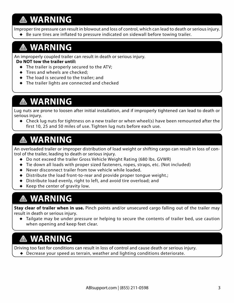
Driving too fast for conditions can result in loss of control and cause death or serious injury. ◆ Decrease your speed as terrain, weather and lighting conditions deteriorate.
WARNING
Improper tire pressure can result in blowout and loss of control, which can lead to death or serious injury. ◆ Be sure tires are inflated to pressure indicated on sidewall before towing trailer.
An improperly coupled trailer can result in death or serious injury. Do NOT tow the trailer until:
◆ The trailer is properly secured to the ATV; ◆ Tires and wheels are checked; ◆ The load is secured to the trailer; and ◆ The trailer lights are connected and checked
Lug nuts are prone to loosen after initial installation, and if improperly tightened can lead to death or serious injury.
◆ Check lug nuts for tightness on a new trailer or when wheel(s) have been remounted after the first 10, 25 and 50 miles of use. Tighten lug nuts before each use.
An overloaded trailer or improper distribution of load weight or shifting cargo can result in loss of con-trol of the trailer, leading to death or serious injury.
◆ Do not exceed the trailer Gross Vehicle Weight Rating (680 lbs. GVWR) ◆ Tie down all loads with proper sized fasteners, ropes, straps, etc. (Not included) ◆ Never disconnect trailer from tow vehicle while loaded. ◆ Distribute the load front-to-rear and provide proper tongue weight.; ◆ Distribute load evenly, right to left, and avoid tire overload; and ◆ Keep the center of gravity low.
WARNING
WARNING
WARNING
WARNING
Stay clear of trailer when in use. Pinch points and/or unsecured cargo falling out of the trailer may result in death or serious injury.
◆ Tailgate may be under pressure or helping to secure the contents of trailer bed, use caution when opening and keep feet clear.
WARNING
4 ABIsupport.com | (855) 211-0598
M A I N T E N A N C E & C A R E
1 Y E A R L I M I T E D WA R R A N T Y
AT TA C H I N G T O Y O U R AT V
◆ Wheel Hub Lubrication: Grease the hubs once a year, or before long periods of storage. There are grease fittings located on the back of each hub for this purpose. If your hub does not have a grease fitting, you will have to hand pack your bearings. When greasing or packing your bearings you will want to use Hi-Temp Wheel Bearing grease only. If using a grease gun, we recommend about 2 pumps for this.
◆ Spray down after each use. ◆ Store in a dry location to prevent premature rust.
ABI recommends using a 2’’ female receiver mounted to the frame of your ATV. We cannot recommend using a 1’’-2’’ converter due to the stress it places on your ATV and the frame of the Rebel Rough Terrain Trailer. Please see your ATV dealer for the correct 2’’female receiver system for your Rebel Rough Terrain Trailer!
TERMS & CONDITIONS“ABI” means Absolute Innovations, Inc. 1320 Third Street, Osceola, IN 46561 - 877.788.7253
The ABI Rascal, Kiser Edge and TR3 Rake products are warranted for one (1) year, from the original invoice date, against defects in materials and/or workmanship when put to normal and designed consumer/residential or commercial use. This warranty is only valid on new equipment to the original purchaser with proof of purchase.
For the purpose of the warranties, “normal & designed use” refers to such uses shown in ABI marketing materials, websites & videos specific to each product and does not include misuse, accidents, or damage due to inadequate maintenance. However, final judgment of “normal & designed use” is the sole opinion of ABI.
The warranty holder is responsible for performing reasonable and proper maintenance. The warranty holder is further responsible for performing replacement of normally wearing parts. Attachments and options for these products are not covered by this warranty. ABI in no way warrants engines, pumps, tanks, tires, electric actuators, tubes or other trade accessories since these items are warranted separately by their respective manufacturers.
ABI’s obligation and or liability, under this warranty, of any product defect or claim for injury or damages is limited to repair or replacement of the product, or payment of the reasonable cost of repair or replacement of the product, at ABI’s sole discretion. The warranty holder is responsible for the return of product or part transportation charges to ABI, if any when product or part return is required. During the warranty period, warranty parts or replacement product will ship by a standard method at no charge to the warranty holder, in the United States & Canada only. Expedited shipping of warranty parts or replacement product is the responsibility of the warranty holder.
To secure warranty service the warranty holder must, (1) report the defect immediately to ABI customer service for warranty consideration within the applicable warranty term in writing and discontinue use of the product; (2) present photographic evidence of the warranty claim and valid proof of purchase; (3) return the product or part to ABI or independent service technician within 30 days of defect discovery or failure for return, inspection or repair, if required. If ABI is unable
to repair the product to conform to the warranty after a reasonable number of attempts, ABI will provide, at its option, one of the following: (a) a replacement for the product or, (b) a full refund of the purchase price. Repair, replacement, or refunds are the warranty holder’s EXCLUSIVE remedies against ABI under this limited warranty.
ABI IS NOT RESPONSIBLE FOR THE FOLLOWING: (1) Equipment purchased used; (2) Any equipment that has been altered or modified in ways not approved by ABI, including, but not limited to, unauthorized repair, and acts of God; (3) Depreciation or damage caused by normal wear, lack of reasonable and proper maintenance, failure to follow operating instructions/recommendations; misuse, lack of proper protection during storage or use, vandalism, the elements, collision or accident; (4) Normal maintenance/wear parts and/or service, including but not limited to, tips, shanks, teeth, scarifiers, top-links, finish rakes, cables, chains, sprockets, switches, pins, bolts, leveling blades, profile blades, tires, rims, bearings and wear plates. Periodic replacement of normally wearing parts is the responsibility of the warranty holder.
To the extent permitted by law, the limited warranty stated above is the exclusive warranty given by ABI, without purchase of optional additional charge extended warranty, to the original purchaser, and ABI disclaims any other warranties. There are no other warranties, either express or implied, including any warranty of merchantability, fitness for a particular purpose, or arising from course of dealing or trade usage. ABI shall not be liable in any event for incidental or consequential or other special damages under any theory of strict liability or negligence, or expenses of any kind, including, but not limited to, personal injury, damage to property, cost of equipment rentals, loss of profit, or cost of hiring services to perform tasks normally performed by these products. ABI reserves the right to make improvements in design or changes in specifications at any time, without incurring any obligation to owners of units previously sold.
Some jurisdictions do not allow limitations on how long an implied warranty lasts or the exclusion or limitation of incidental or consequential damages so the above limitations and exclusions may not apply to you. This warranty gives you specific legal rights, and you may also have other rights, which vary from jurisdiction to jurisdiction.

5ABIsupport.com | (855) 211-0598
PA R T S I N C L U D E D
TOOLS NEEDED
� 2 Axle assemblies� 2 Wheels� 2 Tree kickers� 1 Tailgate� Main body� ATV/hitch attachment� Trailer/Hitch attachment� 2 fenders� Winch bracket (optional)� Winch (optional)
�
�
�
�
�
� � � �
�
◆ 2 able-bodied individuals ◆ A flat, stable work area ◆ Open or box end wrenches:
13/16’’, 7/8’’, 3/4’’, and 7/16’’ size (a socket set is also suitable)
◆ Hammer

6 ABIsupport.com | (855) 211-0598
H A R D WA R E I N C L U D E D
A B
C D
E F
G
H
I
K
L
Body, Fenders, & Tree Kickers
Axle Assembly
Hitch Assembly
Optional Winch Hardware(Packaged Separately)
3 Self-locking Linchpins (N)
A. (24) 1/4’’ x 3/4’’ Carriage BoltsB. (24) 1/4’’ Flat WashersC. (24) 1/4’’ Lock WashersD. (24) 1/4’’ Hex Nuts
E. (8) 1/2’’x 1 1/4’’ Hex BoltsF. (8) 1/2’’ Flat WashersG. (8) 1/2’’ Nuts (top & side view)H. (10) Lug Nuts (top & side view)I. (8) 1/2’’ Lock Washers
J. (2) 9/16’’x 4 1/2’’ Hex BoltsK. (2) 9/16’’ Flat WashersL. (2) 9/16’’ Lock WashersM. (2) 9/16’’ Nuts (top & side view)
J
M
NOTE! The two flat washers, lock washers, and nuts intended to be used with the hitch assembly are slightly larger (9/16’’) than the other washers and nuts included for the axle assembly (1/2’’). MAKE SURE you separate the two larger flat washers, lock washers, and nuts for use with the hitch.
(Pictured at actual size for easy categorization)
NOTE! 2 additional parts J, K, L, and M are also included in the optional winch hardware.
A. (3) 5/16’’ x 3/4’’ Hex BoltsB. (3) 5/16’’ Lock WashersC. (3) 5/16’’ Flat WashersD. (3) 5/16’’ Hex Nuts
N
O P
Q R
7ABIsupport.com | (855) 211-0598
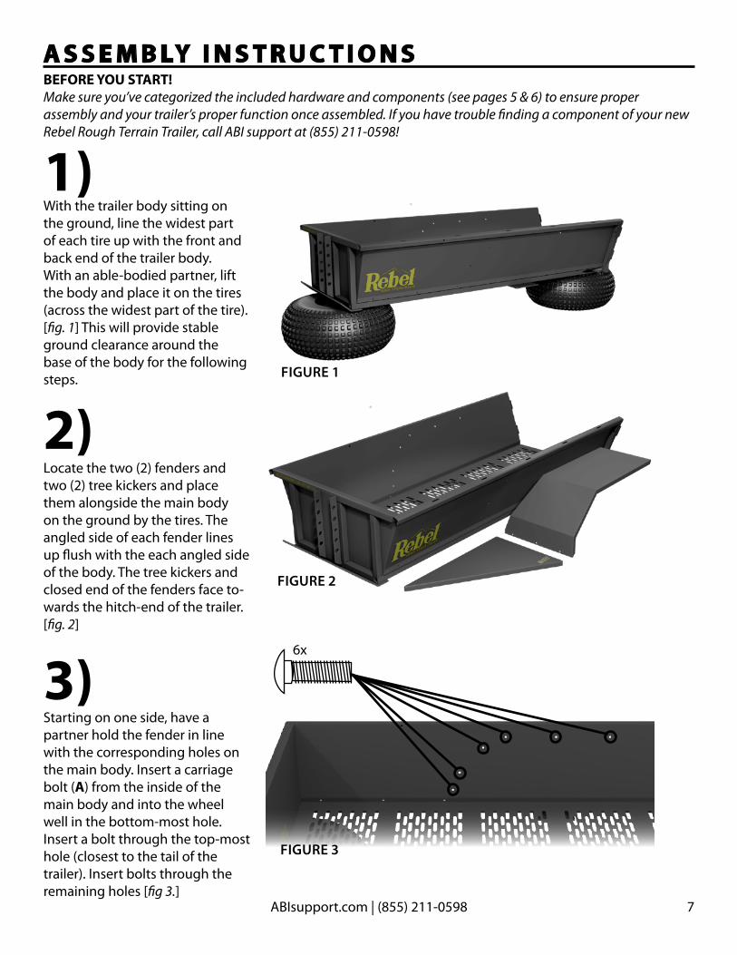
1)
2)
With the trailer body sitting on the ground, line the widest part of each tire up with the front and back end of the trailer body. With an able-bodied partner, lift the body and place it on the tires (across the widest part of the tire). [fig. 1] This will provide stable ground clearance around the base of the body for the following steps.
Locate the two (2) fenders and two (2) tree kickers and place them alongside the main body on the ground by the tires. The angled side of each fender lines up flush with the each angled side of the body. The tree kickers and closed end of the fenders face to-wards the hitch-end of the trailer. [fig. 2]
A S S E M B LY I N S T R U C T I O N SBEFORE YOU START!Make sure you’ve categorized the included hardware and components (see pages 5 & 6) to ensure proper assembly and your trailer’s proper function once assembled. If you have trouble finding a component of your new Rebel Rough Terrain Trailer, call ABI support at (855) 211-0598!
FIGURE 2
FIGURE 1
3)Starting on one side, have a partner hold the fender in line with the corresponding holes on the main body. Insert a carriage bolt (A) from the inside of the main body and into the wheel well in the bottom-most hole. Insert a bolt through the top-most hole (closest to the tail of the trailer). Insert bolts through the remaining holes [fig 3.]
FIGURE 3
6x

8 ABIsupport.com | (855) 211-0598
4)
5)
Place a 1/4’’ flat washer, lock washer, and nut (B, C, D) on each of the six bolts attaching the fender to the main body [fig.4]. Start with the outer-most bolts. DO NOT COMPLETELY TIGHTEN NUTS until indicated. Ensure that each carriage bolt head fits into the square hole to enable a tight fit.
While a partner holds the tree kicker in place (flush against the main body and front edge of the untightened fender), place 1/4’’ carriage bolts (A) through the main body and into each hole on the tree kicker, starting with the center main body hole, then the outermost fender hole, and then each remaining hole. [fig. 5]
FIGURE 5
FIGURE 4
6x
6x

9ABIsupport.com | (855) 211-0598
6)Attach a 1/4’’ washer, lock washer, and a nut (B, C, D) to each of the bolts attaching the tree-kicker to the main body and fender [fig. 6]. DO NOT COMPLETELY TIGHTEN NUTS until all nuts are in place. En-sure that each carriage bolt head fits into the square hole to enable a tight fit.
FIGURE 6 6x
8)Repeat steps 3-7 with the opposite side’s fender and tree kicker [figs. 3-6]
While a partner holds the fender and tree-kicker steady, slowly work through and tighten the nuts with a wrench, ensuring that the fender stays flush and level with the main body, and that the tree kicker remains flush with the front edge of the fender and the main body [fig. 6]. Ensure that each carriage bolt head stays in the corresponding square hole.
7)
Tip: For additional help, see www.RebelTrailer.com to watch a video of the assembly! (located under “support” tab)
10 ABIsupport.com | (855) 211-0598
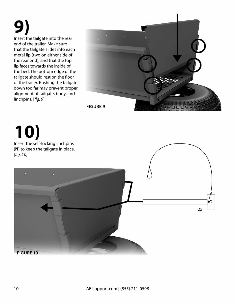
9)
10)
Insert the tailgate into the rear end of the trailer. Make sure that the tailgate slides into each metal lip (two on either side of the rear end), and that the top lip faces towards the inside of the bed. The bottom edge of the tailgate should rest on the floor of the trailer. Pushing the tailgate down too far may prevent proper alignment of tailgate, body, and linchpins. [fig. 9]
Insert the self-locking linchpins (N) to keep the tailgate in place. [fig. 10]
FIGURE 10
FIGURE 9
2x
11ABIsupport.com | (855) 211-0598
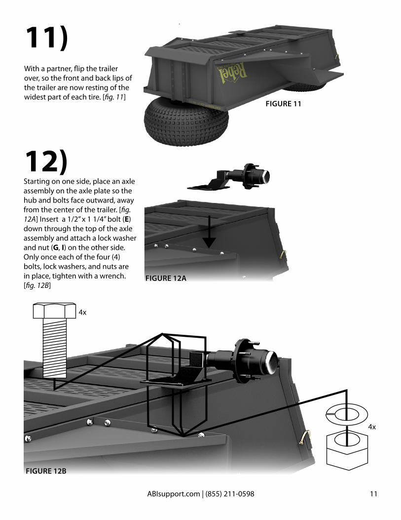
11)With a partner, flip the trailer over, so the front and back lips of the trailer are now resting of the widest part of each tire. [fig. 11]
FIGURE 11
12)Starting on one side, place an axle assembly on the axle plate so the hub and bolts face outward, away from the center of the trailer. [fig. 12A] Insert a 1/2’’ x 1 1/4’’ bolt (E)down through the top of the axle assembly and attach a lock washer and nut (G, I) on the other side. Only once each of the four (4) bolts, lock washers, and nuts are in place, tighten with a wrench. [fig. 12B]
FIGURE 12B
FIGURE 12A
4x
4x
12 ABIsupport.com | (855) 211-0598
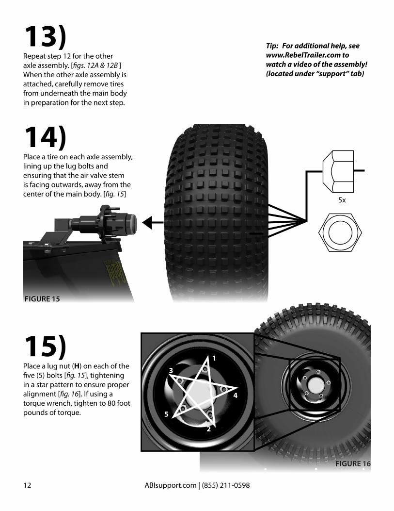
14)
15)
Place a tire on each axle assembly, lining up the lug bolts and ensuring that the air valve stem is facing outwards, away from the center of the main body. [fig. 15]
Place a lug nut (H) on each of the five (5) bolts [fig. 15], tightening in a star pattern to ensure proper alignment [fig. 16]. If using a torque wrench, tighten to 80 foot pounds of torque.
13)Repeat step 12 for the other axle assembly. [figs. 12A & 12B ] When the other axle assembly is attached, carefully remove tires from underneath the main body in preparation for the next step.
FIGURE 15
FIGURE 16
1
4
2
5
3
5x
Tip: For additional help, see www.RebelTrailer.com to watch a video of the assembly! (located under “support” tab)
13ABIsupport.com | (855) 211-0598
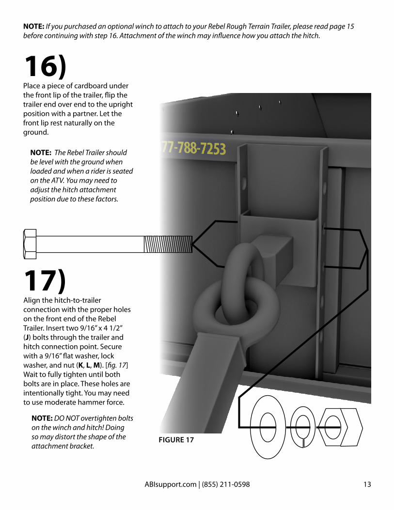
16)
17)
Place a piece of cardboard under the front lip of the trailer, flip the trailer end over end to the upright position with a partner. Let the front lip rest naturally on the ground.
Align the hitch-to-trailer connection with the proper holes on the front end of the Rebel Trailer. Insert two 9/16’’ x 4 1/2’’ (J) bolts through the trailer and hitch connection point. Secure with a 9/16’’ flat washer, lock washer, and nut (K, L, M). [fig. 17] Wait to fully tighten until both bolts are in place. These holes are intentionally tight. You may need to use moderate hammer force.
FIGURE 17
NOTE: If you purchased an optional winch to attach to your Rebel Rough Terrain Trailer, please read page 15 before continuing with step 16. Attachment of the winch may influence how you attach the hitch.
NOTE: The Rebel Trailer should be level with the ground when loaded and when a rider is seated on the ATV. You may need to adjust the hitch attachment position due to these factors.
NOTE: DO NOT overtighten bolts on the winch and hitch! Doing so may distort the shape of the attachment bracket.

14 ABIsupport.com | (855) 211-0598
18)Insert the ATV/hitch attachment into the open end of the trailer/hitch attachment [fig. 18A]
Insert a self-locking linchpin (N)through the hitch attachment. Lock the linchpin to secure.
FIGURE 18A
FIGURE 18B
Congratulations! Your Rebel Rough Terrain Trailer is ready to use.

15ABIsupport.com | (855) 211-0598
O P T I O N A L W I N C H A S S E M B LY1) The winch attachment connects to the top two holes of the brackets located on the front of the main body. The top plate should angle down towards the bed of the trailer. [fig. 19]
NOTE: Depending on your payload and ATV size, the hitch and winch may share one or both holes.
2) Once you’ve determined the location of the hitch and winch, thread the two large (9/16’’ x 4.5’’) bolts included with the hitch assembly through the winch, main body bracket (and possibly the hitch attachment point), and out the other side. Secure with the included flat washer, lock washer, and nut. [fig. 19]
3) Place the winch assembly on top of the winch attachment, lining up the three holes for bolts. [fig. 20]
4) Insert three (3) 5/16’’ x 3/4’’bolts (O) included in the optional winch packaging up through the holes in the top of the winch attachment and secure with three 5/16’’ flat washers, lock washers, and nuts (P,Q,R). Tighten. [fig. 20]
Please return to page 13 to ensure you’ve fully completed the assembly of your Rebel Trailer!
FIGURE 19
FIGURE 20

ABIsupport.com | (855) 211-0598Enjoy your Rebel Rough Terrain Trailer by ABI, Inc.!
ABI – Absolute Innovations, Inc.1320 Third St.
Osceola, IN 46561