rear sensor unit and actuator - …pdf.textfiles.com/manuals/automobile/nissan/frontier/... ·...
TRANSCRIPT
BRAKE SYSTEM
SECTIONBRCONTENTS
PRECAUTIONS ...............................................................5Supplemental Restraint System (SRS) ″AIRBAG″ and ″SEAT BELT PRE-TENSIONER″ ...............5Precautions for Brake System.....................................5Wiring Diagrams and Trouble Diagnosis.....................6
PREPARATION ...............................................................7Special Service Tools ..................................................7Commercial Service Tools ...........................................7
NOISE, VIBRATION AND HARSHNESS (NVH)TROUBLESHOOTING .....................................................8
NVH Troubleshooting Chart.........................................8ON-VEHICLE SERVICE ..................................................9
Checking Brake Fluid Level.........................................9Checking Brake Line ...................................................9Changing Brake Fluid ..................................................9Brake Burnishing Procedure......................................10Bleeding Brake System .............................................11
BRAKE HYDRAULIC LINE ...........................................12Hydraulic Circuit.........................................................12Removal.....................................................................13Inspection...................................................................13Installation..................................................................13
PROPORTIONING VALVE (VG33E AND VG33ER) ....14Inspection...................................................................14Removal and Installation (Built-in type).....................14
LOAD SENSING VALVE (KA24DE) .............................15Inspection...................................................................15Removal and Installation ...........................................16
BRAKE PEDAL AND BRACKET..................................17Removal and Installation ...........................................17Inspection...................................................................17Adjustment .................................................................18
MASTER CYLINDER.....................................................19Removal.....................................................................19Disassembly...............................................................19Inspection...................................................................20Assembly ...................................................................20Installation..................................................................21
BRAKE BOOSTER........................................................22
On-vehicle Service.....................................................22OPERATING CHECK ...............................................22AIRTIGHT CHECK ...................................................22
Removal.....................................................................22Inspection...................................................................22
OUTPUT ROD LENGTH CHECK ..............................22Installation..................................................................23
VACUUM PIPING...........................................................24Vacuum Hose ............................................................24Removal and Installation ...........................................24Inspection...................................................................25
HOSES AND CONNECTORS ...................................25CHECK VALVE........................................................25
FRONT DISC BRAKE ...................................................26Pad Replacement ......................................................26Removal.....................................................................27Disassembly...............................................................28Inspection...................................................................28
CALIPER.................................................................28ROTOR...................................................................28
Assembly ...................................................................29Installation..................................................................29
REAR DRUM BRAKE ...................................................30Components...............................................................30Removal.....................................................................31Inspection...................................................................32
WHEEL CYLINDER..................................................32Wheel Cylinder Overhaul...........................................32Inspection...................................................................32
DRUM.....................................................................32LINING....................................................................32
Installation..................................................................33LT30A MODEL.........................................................33
PARKING BRAKE CONTROL ......................................35Components...............................................................35Removal and Installation ...........................................36Inspection...................................................................36Adjustment .................................................................36
GI
MA
EM
LC
EC
FE
CL
MT
AT
TF
PD
AX
SU
ST
RS
BT
HA
SC
EL
IDX
KA24DE
DESCRIPTION ...............................................................37Purpose......................................................................37Operation ...................................................................37ABS Hydraulic Circuit ................................................37System Components .................................................38System Description....................................................38
REAR SENSOR.......................................................38ABS CONTROL UNIT...............................................38
Removal and Installation ...........................................39REAR SENSOR.......................................................39ACTUATOR.............................................................39
TROUBLE DIAGNOSES................................................40How to Perform Trouble Diagnoses for Quickand Accurate Repair ..................................................40
INTRODUCTION......................................................40WORK FLOW ..........................................................41
Preliminary Check......................................................42Component Parts and Harness ConnectorLocation .....................................................................45Schematic ..................................................................46Wiring Diagram - ABS - .............................................47Self-diagnosis ............................................................49
CHECKING THE NUMBER OF WARNING LAMPFLASHES................................................................49SELF-DIAGNOSIS PROCEDURE 1...........................49SELF-DIAGNOSIS PROCEDURE 2...........................51MALFUNCTION CODE/SYMPTOM CHART ...............52
Main Power Supply and Ground Circuit Check ........52TROUBLE DIAGNOSES FOR SELF-DIAGNOSTICITEMS.............................................................................56
ABS Actuator ISO Solenoid Short or Open...............56MALFUNCTION CODE NO. 2 OR 7 ..........................56
ABS Actuator ISO Blocked ........................................57MALFUNCTION CODE NO. 4 ...................................57
ABS Actuator Dump Solenoid Short Circuit orOpen ..........................................................................58
MALFUNCTION CODE NO. 3 OR 8 ..........................58Rear Sensor Open or Short ......................................60
MALFUNCTION CODE NO. 9 OR 10.........................60Sensor Signal Erratic.................................................60
MALFUNCTION CODE NO. 6 ...................................60ABS Control Unit .......................................................61
MALFUNCTION CODE NO. 13, 14 OR 15 .................61ABS Actuator .............................................................61
MALFUNCTION CODE NO. 5 ...................................61TROUBLE DIAGNOSES FOR SYMPTOMS .................62
1. Pedal Vibration or Noise .......................................622. Long Stopping Distance ........................................633. Unexpected Pedal Action ......................................634. ABS Does Not Work..............................................645. ABS Works Frequently ..........................................64Electrical Components Inspection .............................65
REAR SENSOR UNIT AND ACTUATOR....................65
VG33E AND VG33ER (2WD)
DESCRIPTION ...............................................................68Purpose......................................................................68Operation ...................................................................68ABS Hydraulic Circuit ................................................68System Components .................................................69System Description....................................................70
WHEEL SENSOR ....................................................70ABS ACTUATOR AND ELECTRIC UNIT(CONTROL UNIT) ....................................................70
Removal and Installation ...........................................71FRONT WHEEL SENSORS......................................71REAR WHEEL SENSOR ..........................................71ABS ACTUATOR AND ELECTRIC UNIT....................72
TROUBLE DIAGNOSES................................................73How to Perform Trouble Diagnoses for Quickand Accurate Repair ..................................................73
INTRODUCTION......................................................73WORK FLOW ..........................................................74
Preliminary Check......................................................75Component Parts and Harness ConnectorLocation .....................................................................78Schematic ..................................................................79Wiring Diagram - ABS - .............................................80
ON BOARD DIAGNOSTIC SYSTEMDESCRIPTION ...............................................................83
Self-diagnosis ............................................................83FUNCTION..............................................................83SELF-DIAGNOSIS PROCEDURE..............................83HOW TO READ SELF-DIAGNOSTIC RESULTS(MALFUNCTION CODES) ........................................84HOW TO ERASE SELF-DIAGNOSTIC RESULTS(MALFUNCTION CODES) ........................................84
CONSULT-II ...............................................................85CONSULT-II APPLICATION TO ABS..........................85ECU (ABS CONTROL UNIT) PART NUMBERMODE.....................................................................85
CONSULT-II Inspection Procedure............................86SELF-DIAGNOSIS PROCEDURE..............................86SELF-DIAGNOSTIC RESULTS MODE.......................87DATA MONITOR PROCEDURE................................88ACTIVE TEST PROCEDURE ....................................88DATA MONITOR MODE...........................................90ACTIVE TEST MODE ...............................................91
Ground Circuit Check ................................................91ABS ACTUATOR AND ELECTRIC UNIT GROUND.....91
TROUBLE DIAGNOSIS - GENERALDESCRIPTION ...............................................................92
Malfunction Code/Symptom Chart.............................92TROUBLE DIAGNOSES FOR SELF-DIAGNOSTICITEMS.............................................................................93
Wheel Sensor or Rotor..............................................93
CONTENTS (Cont’d)
BR-2

MALFUNCTION CODE NO. 21, 22, 25, 26, 35, 36OR 18.....................................................................93
ABS Actuator Solenoid Valve and Solenoid ValveRelay..........................................................................95
MALFUNCTION CODE NO. 41, 42, 45, 46, 55, 56OR 63.....................................................................95
Motor Relay or Motor.................................................97MALFUNCTION CODE NO. 61 .................................97
Low Voltage ...............................................................99MALFUNCTION CODE NO. 57 .................................99
Control Unit..............................................................101MALFUNCTION CODE NO. 71 ...............................101
TROUBLE DIAGNOSES FOR SYMPTOMS ...............1021. ABS Works Frequently ........................................1022. Unexpected Pedal Action ....................................1033. Long Stopping Distance ......................................1044. ABS Does Not Work............................................1045. Pedal Vibration and Noise...................................1056. Warning Lamp Does Not Come On WhenIgnition Switch Is Turned ON...................................1057. Warning Lamp Stays On When Ignition SwitchIs Turned On............................................................107
VG33E AND VG33ER (4WD)
DESCRIPTION .............................................................110Purpose....................................................................110Operation .................................................................110ABS Hydraulic Circuit ..............................................110System Components ............................................... 111System Description.................................................. 111
WHEEL SENSOR .................................................. 111CONTROL UNIT (BUILT-IN ABS ACTUATOR ANDELECTRIC UNIT)................................................... 111ABS ACTUATOR AND ELECTRIC UNIT..................112G SENSOR ...........................................................112
TROUBLE DIAGNOSIS - INTRODUCTION................113How to Perform Trouble Diagnoses for Quickand Accurate Repair ................................................113
INTRODUCTION....................................................113TROUBLE DIAGNOSIS - BASIC INSPECTION .........114
Preliminary Check....................................................114Ground Circuit Check ..............................................117
ABS ACTUATOR AND ELECTRIC UNIT GROUND...117Component Parts and Harness ConnectorLocation ...................................................................118Schematic ................................................................119Wiring Diagram - ABS - ...........................................120
ON BOARD DIAGNOSTIC SYSTEMDESCRIPTION .............................................................123
Self-diagnosis (Without CONSULT-II) .....................123FUNCTION............................................................123SELF-DIAGNOSIS PROCEDURE............................123
HOW TO READ SELF-DIAGNOSTIC RESULTS(MALFUNCTION CODES) ......................................124HOW TO ERASE SELF-DIAGNOSTIC RESULTS(MALFUNCTION CODES) ......................................124
TROUBLE DIAGNOSIS - GENERALDESCRIPTION .............................................................125
Malfunction Code Chart (Without CONSULT-II)......125Symptom Chart........................................................125CONSULT-II .............................................................126
CONSULT-II APPLICATION TO ABS........................126ECU (ABS CONTROL UNIT) PART NUMBERMODE...................................................................126
CONSULT-II Inspection Procedure..........................127SELF-DIAGNOSIS PROCEDURE............................127SELF-DIAGNOSTIC RESULTS MODE.....................128DATA MONITOR PROCEDURE..............................129ACTIVE TEST PROCEDURE ..................................130DATA MONITOR MODE.........................................131ACTIVE TEST MODE .............................................131
TROUBLE DIAGNOSES FOR SELF-DIAGNOSTICITEMS...........................................................................132
Wheel Sensor or Rotor............................................132DIAGNOSTIC PROCEDURE...................................132
ABS Actuator Solenoid Valve or Solenoid ValveRelay........................................................................135
DIAGNOSTIC PROCEDURE...................................135Motor Relay or Motor...............................................137
DIAGNOSTIC PROCEDURE...................................137Low Voltage .............................................................139
DIAGNOSTIC PROCEDURE...................................139G Sensor and Circuit ...............................................141
DIAGNOSTIC PROCEDURE...................................141Control Unit..............................................................143
DIAGNOSTIC PROCEDURE...................................143TROUBLE DIAGNOSES FOR SYMPTOMS ...............144
1. ABS Works Frequently ........................................1442. Unexpected Pedal Action ....................................1443. Long Stopping Distance ......................................1464. ABS Does Not Work............................................1465. Pedal Vibration and Noise...................................1466. Warning Lamp Does Not Come On WhenIgnition Switch Is Turned On ...................................1477. Warning Lamp Stays On When Ignition SwitchIs Turned On............................................................148
REMOVAL AND INSTALLATION ...............................152Front Wheel Sensor.................................................152Rear Wheel Sensor .................................................152Front Sensor Rotor ..................................................153
REMOVAL.............................................................153INSTALLATION......................................................153
Rear Sensor Rotor...................................................153REMOVAL.............................................................153INSTALLATION......................................................153
G Sensor..................................................................153
CONTENTS (Cont’d)
BR-3
GI
MA
EM
LC
EC
FE
CL
MT
AT
TF
PD
AX
SU
ST
RS
BT
HA
SC
EL
IDX

ABS Actuator and Electric Unit................................154REMOVAL.............................................................154INSTALLATION......................................................154
SERVICE DATA AND SPECIFICATIONS (SDS) .......155General Specifications.............................................155
Disc Brake ...............................................................155Drum Brake..............................................................155Brake Pedal .............................................................155Parking Brake Control .............................................156
CONTENTS (Cont’d)
BR-4
Supplemental Restraint System (SRS) “AIRBAG” and “SEAT BELT PRE-TENSIONER”
NEBR0199
The Supplemental Restraint System such as “AIR BAG” and “SEAT BELT PRE-TENSIONER” used along witha seat belt, help to reduce the risk or severity of injury to the driver and front passenger in a frontal collision.The Supplemental Restraint System consists of air bag modules (located in the center of the steering wheeland in the instrument panel on the passenger side), seat belt pre-tensioners, a diagnosis sensor unit, warn-ing lamp, wiring harness, and spiral cable.The vehicle (except Crew Cab model) is equipped with a passenger air bag deactivation switch. Because norear seat exists where a rear-facing child restraint can be placed, the switch is designed to turn off the pas-senger air bag so that a rear-facing child restraint can be used in the front passenger seat. The switch islocated in the center of the instrument panel, near the ashtray. When the switch is turned to the ON position,the passenger air bag is enabled and could inflate in a frontal collision. When the switch is turned to the OFFposition, the passenger air bag is disabled and will not inflate in a frontal collision. A passenger air bag OFFindicator on the instrument panel lights up when the passenger air bag is switched OFF. The driver air bagalways remains enabled and is not affected by the passenger air bag deactivation switch.Information necessary to service the system safely is included in the RS section of this Service Manual.WARNING: To avoid rendering the SRS inoperative, which could increase the risk of personal injury or death
in the event of a collision which would result in air bag inflation, all maintenance should be per-formed by an authorized NISSAN dealer.
Improper maintenance, including incorrect removal and installation of the SRS, can lead to per-sonal injury caused by unintentional activation of the system. For removal of Spiral Cable and AirBag Module, see the RS section.
Do not use electrical test equipment on any circuit related to the SRS unless instructed to in thisService Manual. Spiral cable and wiring harnesses (except “SEAT BELT PRE-TENSIONER”) cov-ered with yellow insulation either just before the harness connectors or for the complete harnessare related to the SRS.
The vehicle (except Crew Cab model) is equipped with a passenger air bag deactivation switchwhich can be operated by the customer. When the passenger air bag is switched OFF, the passen-ger air bag is disabled and will not inflate in a frontal collision. When the passenger air bag isswitched ON, the passenger air bag is enabled and could inflate in a frontal collision. After SRSmaintenance or repair, make sure the passenger air bag deactivation switch is in the same posi-tion (ON or OFF) as when the vehicle arrived for service.
SBR686C
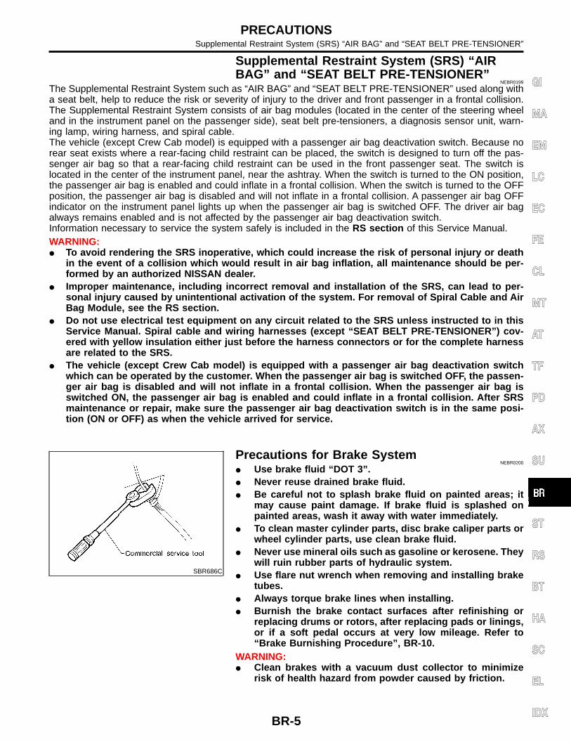
Precautions for Brake SystemNEBR0200
Use brake fluid “DOT 3”. Never reuse drained brake fluid. Be careful not to splash brake fluid on painted areas; it
may cause paint damage. If brake fluid is splashed onpainted areas, wash it away with water immediately.
To clean master cylinder parts, disc brake caliper parts orwheel cylinder parts, use clean brake fluid.
Never use mineral oils such as gasoline or kerosene. Theywill ruin rubber parts of hydraulic system.
Use flare nut wrench when removing and installing braketubes.
Always torque brake lines when installing. Burnish the brake contact surfaces after refinishing or
replacing drums or rotors, after replacing pads or linings,or if a soft pedal occurs at very low mileage. Refer to“Brake Burnishing Procedure”, BR-10.
WARNING: Clean brakes with a vacuum dust collector to minimize
risk of health hazard from powder caused by friction.
PRECAUTIONSSupplemental Restraint System (SRS) “AIR BAG” and “SEAT BELT PRE-TENSIONER”
BR-5
GI
MA
EM
LC
EC
FE
CL
MT
AT
TF
PD
AX
SU
ST
RS
BT
HA
SC
EL
IDX

Wiring Diagrams and Trouble DiagnosisNEBR0201
When you read wiring diagrams, refer to the following: Refer to GI-11, “HOW TO READ WIRING DIAGRAMS”. Refer to EL-9, “POWER SUPPLY ROUTING” for power distribution circuit.When you perform trouble diagnosis, refer to the following: Refer to GI-34, “How to Follow Test Groups In Trouble Diagnoses”. Refer to GI-23, “HOW TO PERFORM EFFICIENT DIAGNOSIS FOR AN ELECTRICAL INCIDENT”.
PRECAUTIONSWiring Diagrams and Trouble Diagnosis
BR-6
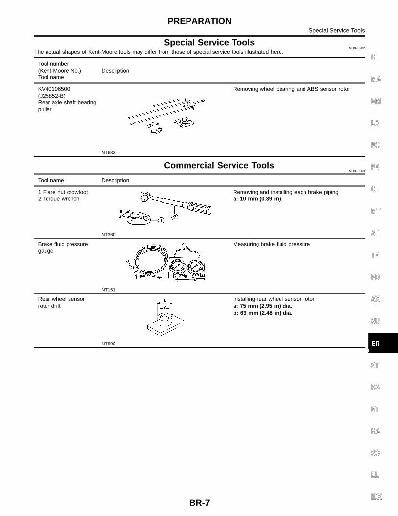
Special Service ToolsNEBR0202
The actual shapes of Kent-Moore tools may differ from those of special service tools illustrated here.
Tool number(Kent-Moore No.)Tool name
Description
KV40106500(J25852-B)Rear axle shaft bearingpuller
NT683
Removing wheel bearing and ABS sensor rotor
Commercial Service ToolsNEBR0203
Tool name Description
1 Flare nut crowfoot2 Torque wrench
NT360
Removing and installing each brake pipinga: 10 mm (0.39 in)
Brake fluid pressuregauge
NT151
Measuring brake fluid pressure
Rear wheel sensorrotor drift
NT509
Installing rear wheel sensor rotora: 75 mm (2.95 in) dia.b: 63 mm (2.48 in) dia.
PREPARATIONSpecial Service Tools
BR-7
GI
MA
EM
LC
EC
FE
CL
MT
AT
TF
PD
AX
SU
ST
RS
BT
HA
SC
EL
IDX

NEBR0204
NVH Troubleshooting ChartNEBR0204S01
Use the chart below to help you find the cause of the symptom. If necessary, repair or replace these parts.
Reference page
BR
-28,
32
BR
-26,
32
BR
-30
BR
-26
— —
BR
-28
— — —
BR
-29
BR
-32
NV
H,
PD
-4.
NV
H,
PD
-4.
NV
H,
AX
-4.
NV
H,
AX
-4.
NV
H,
SU
-3.
NV
H,
SU
-3.
NV
H,
SU
-3.
NV
H,
ST-
5.
Possible causeand SUSPECTED PARTS
Lini
ngs
orpa
ds-
dam
aged
Lini
ngs
orpa
ds-
unev
enw
ear
Ret
urn
sprin
gda
mag
ed
Shi
ms
dam
aged
Rot
oror
drum
imba
lanc
e
Rot
oror
drum
dam
age
Rot
oror
drum
runo
ut
Rot
oror
drum
defo
rmat
ion
Rot
oror
drum
defle
ctio
n
Rot
oror
drum
rust
Rot
orth
ickn
ess
varia
tion
Dru
mou
tof
roun
d
PR
OP
ELL
ER
SH
AF
T
DIF
FE
RE
NT
IAL
DR
IVE
SH
AF
T
AX
LE
SU
SP
EN
SIO
N
TIR
ES
RO
AD
WH
EE
L
ST
EE
RIN
G
Symp-tom
BRAKE
Noise × × × × × × × × × × × ×
Shake × × × × × × × ×
Shimmy, Judder × × × × × × × × × × × × ×
×: Applicable
NOISE, VIBRATION AND HARSHNESS (NVH) TROUBLESHOOTINGNVH Troubleshooting Chart
BR-8

SBR451D
Checking Brake Fluid LevelNEBR0205
Check fluid level in reservoir tank. It should be between MAXand MIN lines on reservoir tank.
If fluid level is extremely low, check brake system. If the brake warning lamp comes on, check brake fluid level
switch and parking brake switch.
SBR389C
Checking Brake LineNEBR0206
CAUTION:If leakage occurs around joints, retighten or, if necessary,replace damaged parts.1. Check brake lines (tubes and hoses) for cracks, deterioration
and other damage. Replace any damaged parts.2. Check for oil leakage by fully depressing brake pedal while
engine is running.
SBR419C
Changing Brake FluidNEBR0207
CAUTION: Refill with new brake fluid “DOT 3”. Always keep fluid level higher than minimum line on res-
ervoir tank. Never reuse drained brake fluid. Be careful not to splash brake fluid on painted areas; it
may cause paint damage. If brake fluid is splashed onpainted areas, wash it away with water immediately.
1. Clean inside of reservoir tank, and refill with new brake fluid.2. Connect a vinyl tube to each air bleeder valve.3. Drain brake fluid from each air bleeder valve by depressing
brake pedal.4. Refill until brake fluid comes out of each air bleeder valve.
Use same procedure as in bleeding hydraulic system to refillbrake fluid.Refer to “Bleeding Brake System”, BR-11.
ON-VEHICLE SERVICEChecking Brake Fluid Level
BR-9
GI
MA
EM
LC
EC
FE
CL
MT
AT
TF
PD
AX
SU
ST
RS
BT
HA
SC
EL
IDX
Brake Burnishing Procedure=NEBR0249
Burnish the brake contact surfaces according to the following pro-cedure after refinishing or replacing drums or rotors, after replac-ing pads or linings, or if a soft pedal occurs at very low mileage.CAUTION:Only perform this procedure under safe road and traffic con-ditions. Use extreme caution.1. Drive the vehicle on a straight smooth road at 50 km/h (31
MPH).2. Use medium brake pedal/foot effort to bring the vehicle to a
complete stop from 50 km/h (31 MPH). Adjust brake pedal/footpressure such that vehicle stopping time equals 3 to 5 sec-onds.
3. To cool the brake system, drive the vehicle at 50 km/h (31MPH) for 1 minute without stopping.
4. Repeat steps 1 to 3, 10 times or more to complete the burnish-ing procedure.
ON-VEHICLE SERVICEBrake Burnishing Procedure
BR-10

SBR995
Bleeding Brake System=NEBR0208
CAUTION: Carefully monitor brake fluid level at master cylinder dur-
ing bleeding operation. If master cylinder is suspected to have air inside, bleed air
from master cylinder first. Refer to “Installation”, BR-21. Fill reservoir with new brake fluid “DOT 3”. Make sure it is
full at all times while bleeding air out of system. Place a container under master cylinder to avoid spillage
of brake fluid. Turn ignition switch OFF and disconnect ABS actuator
(KA24DE)/ABS actuator and electric unit (VG33E andVG33ER) connector or battery cable.
Bleed air in the following order.1. LSV air bleeder (Models equipped with LSV)2. Left rear brake3. Right rear brake4. Left front brake5. Right front brake6. ABS actuator (KA24DE) or ABS actuator and electric unit(VG33E and VG33ER)
SBR419C
1. Connect a transparent vinyl tube to air bleeder valve.2. Fully depress brake pedal several times.3. With brake pedal depressed, open air bleeder valve to release
air.4. Close air bleeder valve.5. Release brake pedal slowly.6. Repeat steps 2. through 5. until clear brake fluid comes out of
air bleeder valve.7. Tighten air bleeder valve.
: 7 - 9 N·m (0.7 - 0.9 kg-m, 61 - 78 in-lb)
ON-VEHICLE SERVICEBleeding Brake System
BR-11
GI
MA
EM
LC
EC
FE
CL
MT
AT
TF
PD
AX
SU
ST
RS
BT
HA
SC
EL
IDX

Hydraulic CircuitNEBR0209
LBR119
WBR160
BRAKE HYDRAULIC LINEHydraulic Circuit
BR-12

SBR992
RemovalNEBR0210
CAUTION: Be careful not to splash brake fluid on painted areas; it
may cause paint damage. If brake fluid is splashed onpainted areas, wash it away with water immediately.
All hoses must be free from excessive bending, twistingand pulling.
1. Connect vinyl tube to air bleeder valve.2. Drain brake fluid from each air bleeder valve by depressing
brake pedal.3. Remove flare nut connecting brake tube and hose, then with-
draw lock spring.4. Cover openings to prevent entrance of dirt whenever discon-
necting brake line.
InspectionNEBR0211
Check brake lines (tubes and hoses) for cracks, deterioration andother damage. Replace any damaged parts.
SBR686C
InstallationNEBR0212
CAUTION: Refill with new brake fluid “DOT 3”. Never reuse drained brake fluid.1. Tighten all flare nuts and connecting bolts.
Flare nut:: 15 - 18 N·m (1.5 - 1.8 kg-m, 11 - 13 ft-lb)
Connecting bolt:: 17 - 19 N·m (1.7 - 2.0 kg-m, 12 - 14 ft-lb)
2. Refill until new brake fluid comes out of each air bleeder valve.3. Bleed air. Refer to “Bleeding Brake System”, BR-11.
BRAKE HYDRAULIC LINERemoval
BR-13
GI
MA
EM
LC
EC
FE
CL
MT
AT
TF
PD
AX
SU
ST
RS
BT
HA
SC
EL
IDX
SBR822BA
SBR823BA
SBR705AA
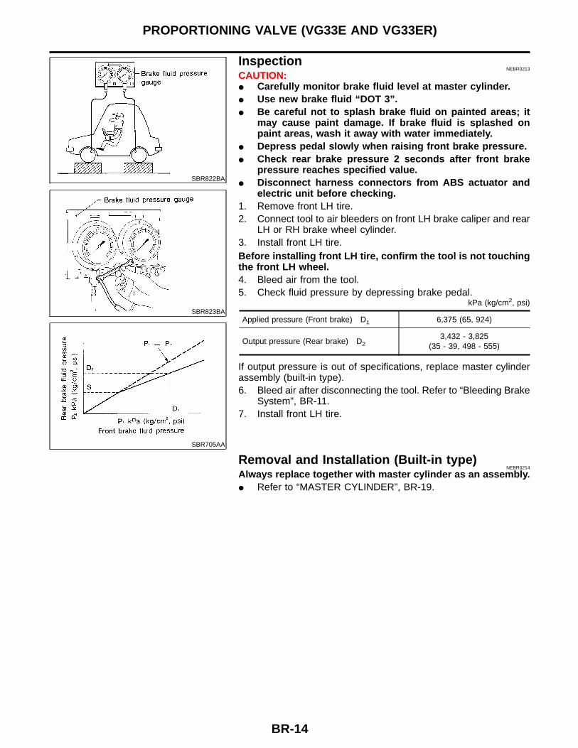
InspectionNEBR0213
CAUTION: Carefully monitor brake fluid level at master cylinder. Use new brake fluid “DOT 3”. Be careful not to splash brake fluid on painted areas; it
may cause paint damage. If brake fluid is splashed onpaint areas, wash it away with water immediately.
Depress pedal slowly when raising front brake pressure. Check rear brake pressure 2 seconds after front brake
pressure reaches specified value. Disconnect harness connectors from ABS actuator and
electric unit before checking.1. Remove front LH tire.2. Connect tool to air bleeders on front LH brake caliper and rear
LH or RH brake wheel cylinder.3. Install front LH tire.Before installing front LH tire, confirm the tool is not touchingthe front LH wheel.4. Bleed air from the tool.5. Check fluid pressure by depressing brake pedal.
kPa (kg/cm2, psi)
Applied pressure (Front brake) D1 6,375 (65, 924)
Output pressure (Rear brake) D23,432 - 3,825
(35 - 39, 498 - 555)
If output pressure is out of specifications, replace master cylinderassembly (built-in type).6. Bleed air after disconnecting the tool. Refer to “Bleeding Brake
System”, BR-11.7. Install front LH tire.
Removal and Installation (Built-in type)NEBR0214
Always replace together with master cylinder as an assembly. Refer to “MASTER CYLINDER”, BR-19.
PROPORTIONING VALVE (VG33E AND VG33ER)
BR-14

InspectionNEBR0278
CAUTION: Carefully monitor brake fluid level at master cylinder. Use new brake fluid “DOT 3”. Be careful not to splash brake fluid on painted areas; it
may cause paint damage. If brake fluid is splashed onpaint areas, wash it away with water immediately.
Depress pedal slowly when raising front brake pressure. Check rear brake pressure 2 seconds after front brake
pressure reaches specified value. Disconnect harness connectors from ABS actuator and
electric unit before checking.
SBR212E
1. Park vehicle on a level surface with vehicle unloaded*.* Fuel, radiator coolant and engine oil full. Spare tire, jack,hand tools and mats in designated positions.
2. Press a lever to the stopper bolt, then adjust length “B” as fol-lows:
Length “B” Reference (Length “L”)
207.7 mm (8.18 in) 217.3 mm (8.56 in)
3. If length “B” is not within specification, adjust sensor springlength.
LOAD SENSING VALVE (KA24DE)Inspection
BR-15
GI
MA
EM
LC
EC
FE
CL
MT
AT
TF
PD
AX
SU
ST
RS
BT
HA
SC
EL
IDX

Removal and Installation=NEBR0279
CAUTION: Refill with new brake fluid “DOT 3”. Be careful not to splash brake fluid on painted areas; it
may cause paint damage. If brake fluid is splashed onpainted areas, wash it away with water immediately.
Do not reuse load sensing valve once it is disassembled. Replace damaged load sensing valve as an assembly. When disassembling, apply multi-purpose grease to all
rubbing areas.
SBR379DB
1. Tighten all flare nuts and mounting bolts.Flare nut:
: 15 - 17 N·m (1.5 - 1.8 kg-m, 11 - 13 ft-lb)2. Refill until new brake fluid comes out of each air bleeder valve.3. Bleed air. Refer to “Bleeding Brake System”, BR-11.
LOAD SENSING VALVE (KA24DE)Removal and Installation
BR-16

Removal and InstallationNEBR0217
ABR815
SBR997
InspectionNEBR0218
Check brake pedal for following items. Brake pedal bend Clevis pin deformation Crack of any welded portion Crack or deformation of clevis pin stopper
BRAKE PEDAL AND BRACKETRemoval and Installation
BR-17
GI
MA
EM
LC
EC
FE
CL
MT
AT
TF
PD
AX
SU
ST
RS
BT
HA
SC
EL
IDX

SBR278AB
AdjustmentNEBR0219
Check brake pedal free height from metal panel.H: Free height
Refer to “Brake Pedal”, BR-155.D: Depressed height
Refer to “Brake Pedal”, BR-155.Under force of 490 N (50 kg, 110 lb) with engine run-ning
C1, C2: Clearance between pedal stopper andthreaded end of stop lamp switch and ASCD switch
0.3 - 1.0 mm (0.012 - 0.039 in)A: Pedal free play
1 - 3 mm (0.04 - 0.12 in)If necessary, adjust brake pedal free height.
SBR930
1. Loosen lock nut and adjust pedal free height by turning brakebooster input rod. Then tighten lock nut.
Make sure that tip of input rod stays inside.2. Loosen lock nut and adjust clearance “C” with stop lamp switch
respectively, Then tighten lock nuts.3. Check pedal free play.Make sure that stop lamp is off when pedal is released.4. Check brake pedal depressed height while engine is running.
If lower than specification, check for leaks, air in system, ordamage to components (master cylinder, wheel cylinder, etc).Then make necessary repairs.
BRAKE PEDAL AND BRACKETAdjustment
BR-18
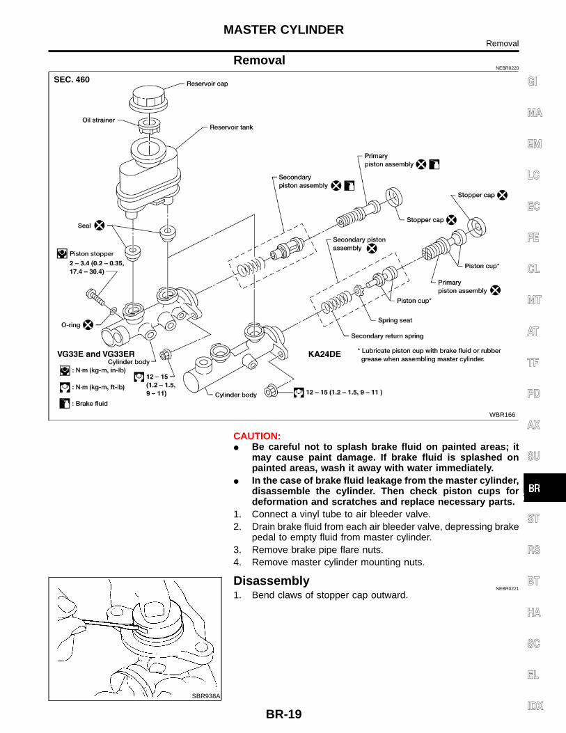
RemovalNEBR0220
WBR166
CAUTION: Be careful not to splash brake fluid on painted areas; it
may cause paint damage. If brake fluid is splashed onpainted areas, wash it away with water immediately.
In the case of brake fluid leakage from the master cylinder,disassemble the cylinder. Then check piston cups fordeformation and scratches and replace necessary parts.
1. Connect a vinyl tube to air bleeder valve.2. Drain brake fluid from each air bleeder valve, depressing brake
pedal to empty fluid from master cylinder.3. Remove brake pipe flare nuts.4. Remove master cylinder mounting nuts.
SBR938A
DisassemblyNEBR0221
1. Bend claws of stopper cap outward.
MASTER CYLINDERRemoval
BR-19
GI
MA
EM
LC
EC
FE
CL
MT
AT
TF
PD
AX
SU
ST
RS
BT
HA
SC
EL
IDX
SBR939A
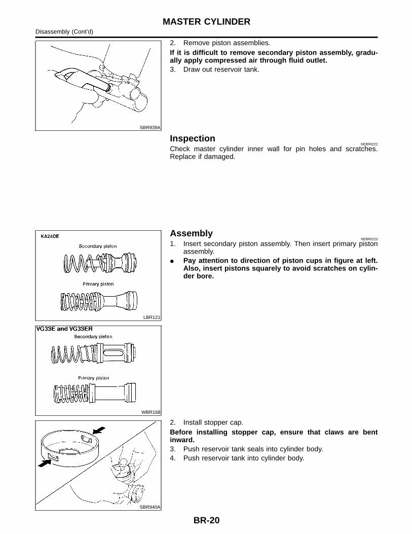
2. Remove piston assemblies.If it is difficult to remove secondary piston assembly, gradu-ally apply compressed air through fluid outlet.3. Draw out reservoir tank.
InspectionNEBR0222
Check master cylinder inner wall for pin holes and scratches.Replace if damaged.
LBR121
WBR168
AssemblyNEBR0223
1. Insert secondary piston assembly. Then insert primary pistonassembly.
Pay attention to direction of piston cups in figure at left.Also, insert pistons squarely to avoid scratches on cylin-der bore.
SBR940A
2. Install stopper cap.Before installing stopper cap, ensure that claws are bentinward.3. Push reservoir tank seals into cylinder body.4. Push reservoir tank into cylinder body.
MASTER CYLINDERDisassembly (Cont’d)
BR-20

ABR190
InstallationNEBR0224
CAUTION: Refill with new brake fluid “DOT 3”. Never reuse drained brake fluid.1. Place master cylinder onto brake booster and secure mount-
ing nuts lightly.2. Torque mounting nuts.
: 12 - 15 N·m (1.2 - 1.5 kg-m, 9 - 11 ft-lb)3. Fill reservoir tank with new brake fluid.4. Plug all ports on master cylinder with fingers to prevent air
suction while releasing brake pedal.5. Have driver depress brake pedal slowly several times until no
air comes out of master cylinder.6. Fit brake lines to master cylinder.7. Tighten flare nuts.
: 15 - 17 N·m (1.5 - 1.8 kg-m, 11 - 13 ft-lb)8. Bleed air from brake system. Refer to “Bleeding Brake
System”, BR-11.
MASTER CYLINDERInstallation
BR-21
GI
MA
EM
LC
EC
FE
CL
MT
AT
TF
PD
AX
SU
ST
RS
BT
HA
SC
EL
IDX

SBR002A
SBR365AA
On-vehicle ServiceNEBR0225
OPERATING CHECKNEBR0225S01
Depress brake pedal several times with engine off. Afterexhausting vacuum, make sure there is no change in pedalstroke.
Depress brake pedal, then start engine. If pedal goes downslightly, operation is normal.
AIRTIGHT CHECKNEBR0225S02
Start engine, and stop it after one or two minutes. Depressbrake pedal several times slowly. Booster is airtight if pedalstroke is less each time.
Depress brake pedal while engine is running, and stop enginewith pedal depressed. The pedal stroke should not changeafter holding pedal down for 30 seconds.
LBR124
RemovalNEBR0226
CAUTION: Be careful not to splash brake fluid on painted areas; it
may cause paint damage. If brake fluid is splashed onpainted areas, wash it away with water immediately.
Be careful not to deform or bend brake pipes duringremoval of booster.
ABR875
InspectionNEBR0227
OUTPUT ROD LENGTH CHECKNEBR0227S01
1. Apply vacuum of −66.7 kPa (−500 mmHg, −19.69 inHg) tobrake booster with a hand vacuum pump.
2. Add preload of 19.6 N (2.0 kg, 4.4 lb) to output rod length.3. Check output rod length.
Specified length:10.275 - 10.525 mm (0.4045 - 0.4144 in)
BRAKE BOOSTEROn-vehicle Service
BR-22
SBR116BE
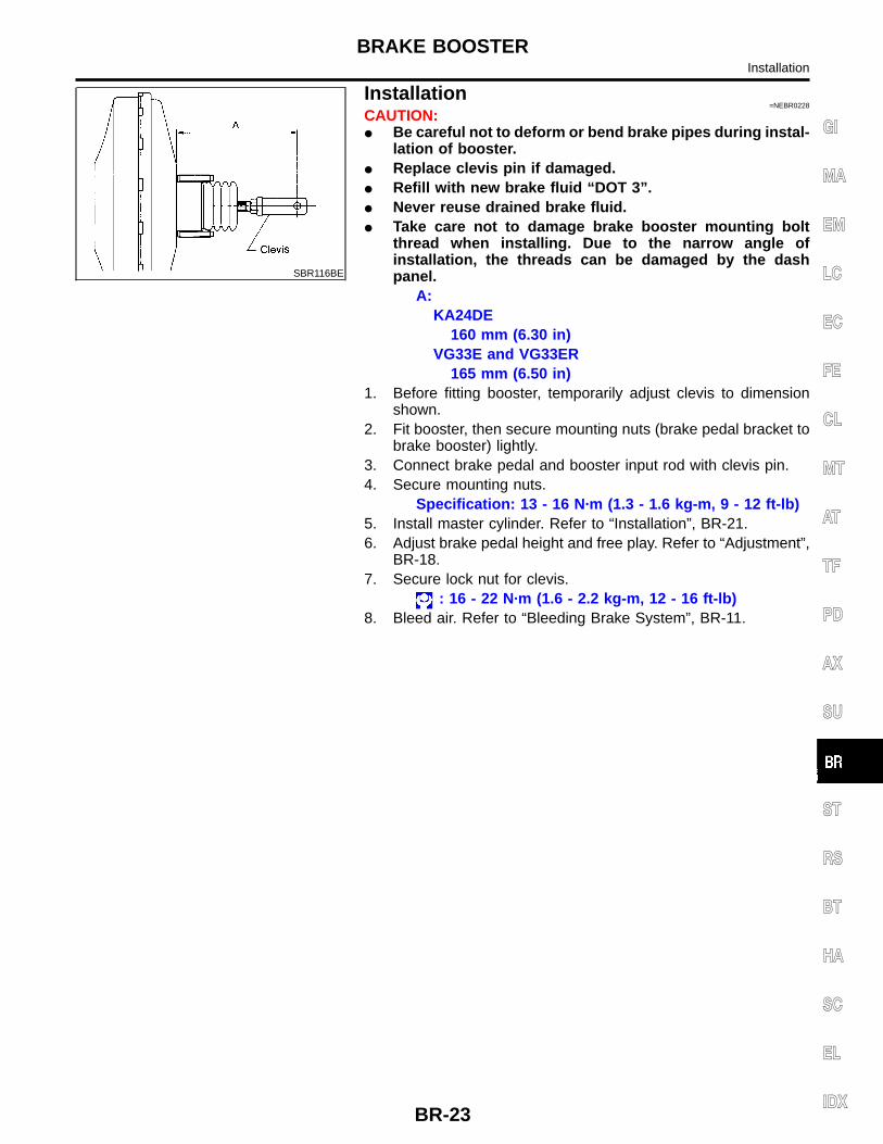
Installation=NEBR0228
CAUTION: Be careful not to deform or bend brake pipes during instal-
lation of booster. Replace clevis pin if damaged. Refill with new brake fluid “DOT 3”. Never reuse drained brake fluid. Take care not to damage brake booster mounting bolt
thread when installing. Due to the narrow angle ofinstallation, the threads can be damaged by the dashpanel.
A:KA24DE
160 mm (6.30 in)VG33E and VG33ER
165 mm (6.50 in)1. Before fitting booster, temporarily adjust clevis to dimension
shown.2. Fit booster, then secure mounting nuts (brake pedal bracket to
brake booster) lightly.3. Connect brake pedal and booster input rod with clevis pin.4. Secure mounting nuts.
Specification: 13 - 16 N·m (1.3 - 1.6 kg-m, 9 - 12 ft-lb)5. Install master cylinder. Refer to “Installation”, BR-21.6. Adjust brake pedal height and free play. Refer to “Adjustment”,
BR-18.7. Secure lock nut for clevis.
: 16 - 22 N·m (1.6 - 2.2 kg-m, 12 - 16 ft-lb)8. Bleed air. Refer to “Bleeding Brake System”, BR-11.
BRAKE BOOSTERInstallation
BR-23
GI
MA
EM
LC
EC
FE
CL
MT
AT
TF
PD
AX
SU
ST
RS
BT
HA
SC
EL
IDX

Vacuum HoseNEBR0229
LBR159
SBR225B
Removal and InstallationNEBR0230
CAUTION:When installing vacuum hoses, pay attention to the followingpoints. Do not apply any oil or lubricants to vacuum hose with
check valve. Insert vacuum tube into vacuum hose as shown. Install vacuum hose with internal check valve, paying
attention to its direction.
VACUUM PIPINGVacuum Hose
BR-24

Inspection=NEBR0231
HOSES AND CONNECTORSNEBR0231S01
Check vacuum lines and connections for airtightness, improperattachment, chafing and deterioration.
SBR844B
CHECK VALVENEBR0231S02
Check vacuum with a vacuum pump.
Connect to booster side Vacuum should exist.
Connect to engine side Vacuum should not exist.
VACUUM PIPINGInspection
BR-25
GI
MA
EM
LC
EC
FE
CL
MT
AT
TF
PD
AX
SU
ST
RS
BT
HA
SC
EL
IDX

Pad ReplacementNEBR0232
WARNING:Clean brakes with a vacuum dust collector to minimize thehazard of airborne particles or other materials.CAUTION: When cylinder body is open, do not depress brake pedal,
or piston will pop out. Be careful not to damage piston boot or get oil on rotor.
Always replace shims when replacing pads. If shims are rusted or show peeling of the rubber coat,
replace them with new shims. It is not necessary to remove connecting bolt except for
disassembly or replacement of caliper assembly. In thiscase, suspend cylinder body with wire so as not to stretchbrake hose.
Burnish the brake contact surfaces after refinishing orreplacing drums or rotors, after replacing pads or linings,or if a soft pedal occurs at very low mileage. Refer to“Brake Burnishing Procedure”, BR-10.
SBR081A
1. Remove master cylinder reservoir cap.2. Remove lower pin bolt.
SBR010B
3. Open cylinder body upward. Then remove pad retainers, innerand outer shims and shim cover (if so equipped).
Standard pad thickness:10 mm (0.39 in)
Pad wear limit:2.0 mm (0.079 in)
Carefully monitor brake fluid level because brake fluid willreturn to reservoir when pushing back piston.
FRONT DISC BRAKEPad Replacement
BR-26

ABR918
1. Main pin2. Pin boot3. Torque member fixing bolt4. Torque member5. Shim cover (if so equipped)6. Inner shim
7. Inner pad8. Pad retainer9. Outer pad10. Outer shim11. Connecting bolt12. Copper washer
13. Main pin bolt14. Bleed valve15. Cylinder body16. Piston seal17. Piston18. Piston boot
SBR083A
RemovalNEBR0233
WARNING:Clean brake pads with a vacuum dust collector to minimize thehazard of airborne particles or other materials.CAUTION:Suspend caliper assembly with wire so as not to stretch brakehose.Remove torque member fixing bolts and connecting bolt.It is not necessary to remove connecting bolt except for dis-assembly or replacement of caliper assembly. In this case,suspend caliper assembly with wire so as not to stretch brakehose.
FRONT DISC BRAKEPad Replacement (Cont’d)
BR-27
GI
MA
EM
LC
EC
FE
CL
MT
AT
TF
PD
AX
SU
ST
RS
BT
HA
SC
EL
IDX

SBR085A
DisassemblyNEBR0234
WARNING:Do not place your fingers in front of piston.CAUTION: Do not scratch or score cylinder wall. CL28VD type front disc brake uses plastic pistons. Handle
them carefully.1. Push out piston and dust covers with compressed air. Use a
wooden block so that both pistons come out evenly.2. Remove piston seal with a suitable tool.
InspectionNEBR0235
CALIPERNEBR0235S01
Cylinder BodyNEBR0235S0101
Check inside surface of cylinder for score, rust, wear, damageand presence of foreign objects. If any of the above conditionsare observed, replace cylinder body.
Minor damage from rust or foreign objects may be eliminatedby polishing surface with a fine emery paper. Replace cylinderbody if necessary.
CAUTION:Use brake fluid to clean. Never use mineral oil.
SBR177C
PistonNEBR0235S0102
CAUTION:Piston sliding surface is plated. Do not polish with emerypaper even if rust or foreign objects are stuck to sliding sur-face.
Slide Pin, Pin Bolt and Pin BootNEBR0235S0103
Check for wear, cracks, rust and other damage. Replace if any ofthe above conditions are observed.
SBR089A
ROTORNEBR0235S02
RunoutNEBR0235S0201
1. Check runout using a dial indicator.Make sure that wheel bearing axial end play is within thespecifications before measuring. Refer to AX-5, “FRONTWHEEL BEARING”.
Maximum runout:0.07 mm (0.0028 in)
2. If the runout is out of specification, find minimum runout posi-tion as follows:
FRONT DISC BRAKEDisassembly
BR-28
a. Remove nuts and rotor from wheel hub.b. Shift the rotor one hole and secure rotor to wheel hub with
nuts.c. Measure runout.d. Repeat steps a. to c. so that minimum runout position can be
found.3. If the runout is still out of specification, turn rotor with on-car
brake lathe (“MAD, DL-8700”, “AMMCO 700 and 705” orequivalent).
SBR020B
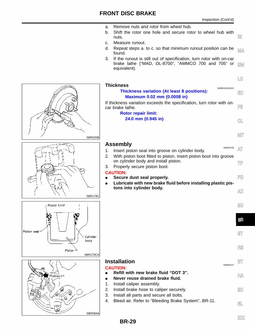
ThicknessNEBR0235S0202
Thickness variation (At least 8 positions):Maximum 0.02 mm (0.0008 in)
If thickness variation exceeds the specification, turn rotor with on-car brake lathe.
Rotor repair limit:24.0 mm (0.945 in)
SBR178C
SBR179CA
AssemblyNEBR0236
1. Insert piston seal into groove on cylinder body.2. With piston boot fitted to piston, insert piston boot into groove
on cylinder body and install piston.3. Properly secure piston boot.CAUTION: Secure dust seal properly. Lubricate with new brake fluid before installing plastic pis-
tons into cylinder body.
SBR084A
InstallationNEBR0237
CAUTION: Refill with new brake fluid “DOT 3”. Never reuse drained brake fluid.1. Install caliper assembly.2. Install brake hose to caliper securely.3. Install all parts and secure all bolts.4. Bleed air. Refer to “Bleeding Brake System”, BR-11.
FRONT DISC BRAKEInspection (Cont’d)
BR-29
GI
MA
EM
LC
EC
FE
CL
MT
AT
TF
PD
AX
SU
ST
RS
BT
HA
SC
EL
IDX

ComponentsNEBR0239
LBR140
WBR161
REAR DRUM BRAKEComponents
BR-30
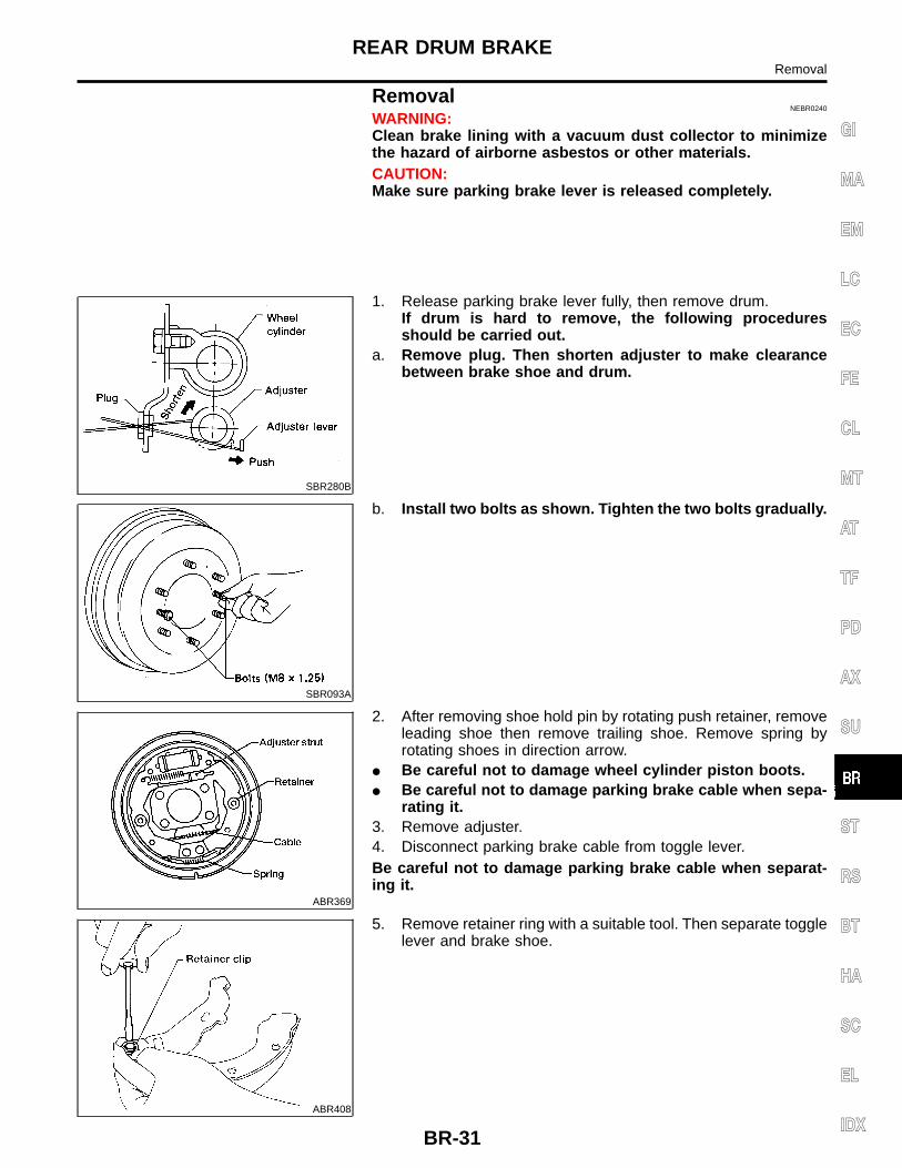
RemovalNEBR0240
WARNING:Clean brake lining with a vacuum dust collector to minimizethe hazard of airborne asbestos or other materials.CAUTION:Make sure parking brake lever is released completely.
SBR280B
1. Release parking brake lever fully, then remove drum.If drum is hard to remove, the following proceduresshould be carried out.
a. Remove plug. Then shorten adjuster to make clearancebetween brake shoe and drum.
SBR093A
b. Install two bolts as shown. Tighten the two bolts gradually.
ABR369
2. After removing shoe hold pin by rotating push retainer, removeleading shoe then remove trailing shoe. Remove spring byrotating shoes in direction arrow.
Be careful not to damage wheel cylinder piston boots. Be careful not to damage parking brake cable when sepa-
rating it.3. Remove adjuster.4. Disconnect parking brake cable from toggle lever.Be careful not to damage parking brake cable when separat-ing it.
ABR408
5. Remove retainer ring with a suitable tool. Then separate togglelever and brake shoe.
REAR DRUM BRAKERemoval
BR-31
GI
MA
EM
LC
EC
FE
CL
MT
AT
TF
PD
AX
SU
ST
RS
BT
HA
SC
EL
IDX

ABR370
InspectionNEBR0241
WHEEL CYLINDERNEBR0241S01
Check wheel cylinder for leakage. Check for wear, damage and loose conditions.
Replace if any such condition exists.
SBR215B
Wheel Cylinder OverhaulNEBR0242
Check all internal parts for wear, rust and damage. Replace ifnecessary.
Pay attention not to scratch cylinder when installing pistons.
SBR095A
InspectionNEBR0243
DRUMNEBR0243S01
Maximum inner diameter (Repair limit):LT26B 261.5 mm (10.30 in)LT30A 296.5 mm (11.67 in)
Contact surface should be fine finished with No. 120 to 150emery paper.
Using a drum lathe, lathe brake drum if it shows scoring, par-tial wear or stepped wear.
After brake drum has been completely reconditioned orreplaced, check drum and shoes for proper contact pattern.
SBR021A
LININGNEBR0243S02
Check lining thickness.Standard lining thickness:
LT26B 5.5 mm (0.217)LT30A 6.1 mm (0.240 in)
Lining wear limit (A):LT26B 1.5 mm (0.059 in)LT30A 1.5 mm (0.059 in)
REAR DRUM BRAKEInspection
BR-32

SBR092B
InstallationNEBR0244
1) Always perform shoe clearance adjustment.2) Burnish the brake contact surfaces after refinishing or
replacing drums or rotors, after replacing pads or linings,or if a soft pedal occurs at very low mileage. Refer to“Brake Burnishing Procedure”, BR-10.
1. Fit toggle lever to brake shoe (trailing side) with retainer ring.
ABR371
2. Apply brake grease to the contact areas shown at left.
SBR217B
3. Shorten adjuster by rotating it. Pay attention to direction of adjuster.
Wheel Screw Depression
Left Left-hand thread Yes
Right Right-hand thread No
4. Connect parking brake cable to toggle lever.5. Install all parts.Be careful not to damage wheel cylinder piston boots.
ABR917
6. Check all parts are installed properly. After installation is completed, adjust shoe-to-drum clear-
ance.7. Install brake drum.8. When installing new wheel cylinder or overhauling wheel
cylinder, bleed air. Refer to “Bleeding Brake System”, BR-11.9. Adjust parking brake. Refer to “Adjustment”, BR-36. Install all the parts by referring to the following figures.
SBR099A
LT30A MODELNEBR0244S02
After installing crank lever on back plate, make sure that thereis no play between crank lever and back plate. If play exists,adjust bolt A and lock nut B.
REAR DRUM BRAKEInstallation
BR-33
GI
MA
EM
LC
EC
FE
CL
MT
AT
TF
PD
AX
SU
ST
RS
BT
HA
SC
EL
IDX

SBR100CA
REAR DRUM BRAKEInstallation (Cont’d)
BR-34

ComponentsNEBR0245
WBR377
PARKING BRAKE CONTROLComponents
BR-35
GI
MA
EM
LC
EC
FE
CL
MT
AT
TF
PD
AX
SU
ST
RS
BT
HA
SC
EL
IDX

Removal and InstallationNEBR0246
Be careful not to damage cable. Make sure there is no free play after installation.
InspectionNEBR0247
1. Check control lever for wear and other damage. Replace ifnecessary.
2. Check wires for discontinuity and deterioration. Replace if nec-essary.
3. Check warning lamp and switch. Replace if necessary.4. Check parts at each connecting portion and, if deformed or
damaged, replace.
SBR980D
ABR912
ABR405
AdjustmentNEBR0248
Adjust parking as follows:1. Fully release parking brake lever.2. Loosen A and rotate B until parking brake pedal loosens.3. Depress brake pedal several times until clicking sound does
not occur from rear brakes.4. Adjust clearance between rear brake shoe and drum.5. Adjust parking brake lever stroke by rotating B.6. Pull parking brake lever with specified force. Check lever
stroke and ensure smooth operation.7. Readjust clearance between rear brake shoe and drum.
PARKING BRAKE CONTROLRemoval and Installation
BR-36

PurposeNEBR0252
The rear wheel anti-lock brake system (ABS) consists of electronic and hydraulic components. It controls rearbraking force so locking of the rear wheels can be avoided.1) Improves proper tracking performance through steering wheel operation during severe braking.2) Eases obstacle avoidance through steering wheel operation during severe braking.3) Improves vehicle stability.
OperationNEBR0253
When the vehicle speed is less than 10 km/h (6 MPH) this system does not work. The rear wheel anti-lock brake system (ABS) has a self-test function. The system turns on the ABS warn-
ing lamp for a few seconds each time the ignition switch is turned ON. After the engine is started, the ABSwarning lamp turns off. The system performs a circuit check when the ignition switch is turned ON. Afterthe engine is started, the ABS warning lamp turns off. If a malfunction is found during this check, the ABSwarning lamp will stay on.
While driving, a mechanical noise may be heard and a slight pedal pulsation may be felt during ABSoperation. This is a normal condition.
ABS Hydraulic CircuitNEBR0254
ABR913
DESCRIPTION KA24DEPurpose
BR-37
GI
MA
EM
LC
EC
FE
CL
MT
AT
TF
PD
AX
SU
ST
RS
BT
HA
SC
EL
IDX

System ComponentsNEBR0255
ABR914
SBR124B
System DescriptionNEBR0256
REAR SENSORNEBR0256S01
The rear sensor unit consist of a gear-shaped sensor rotor and asensor element. The element contains a bar magnet around whicha coil is wound. The sensor rotor is installed at the companionflange of the rear axle housing and the sensor unit is installed onthe rear axle housing. As the rear axle pinion rotates, the sensorgenerates a sine-wave pattern. The frequency and voltageincrease as the rotating speed increases.
ABR403
ABS CONTROL UNITNEBR0256S02
The ABS control unit computes the rear axle rotating speed by thesignal current sent from the sensor unit. Then it supplies a DCcurrent to the ABS actuator. If any electrical malfunction should bedetected in the system, the control unit causes the warning lampto light up. In this condition, the ABS system will be deactivated bythe control unit, and the vehicle’s brake system reverts to normaloperation.
DESCRIPTION KA24DESystem Components
BR-38
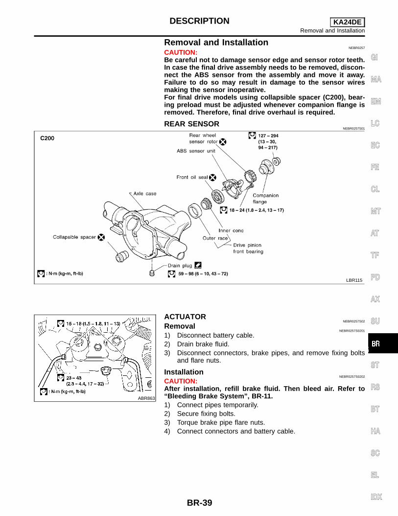
Removal and InstallationNEBR0257
CAUTION:Be careful not to damage sensor edge and sensor rotor teeth.In case the final drive assembly needs to be removed, discon-nect the ABS sensor from the assembly and move it away.Failure to do so may result in damage to the sensor wiresmaking the sensor inoperative.For final drive models using collapsible spacer (C200), bear-ing preload must be adjusted whenever companion flange isremoved. Therefore, final drive overhaul is required.
REAR SENSORNEBR0257S01
LBR115
ABR863
ACTUATORNEBR0257S02
RemovalNEBR0257S0201
1) Disconnect battery cable.2) Drain brake fluid.3) Disconnect connectors, brake pipes, and remove fixing bolts
and flare nuts.
InstallationNEBR0257S0202
CAUTION:After installation, refill brake fluid. Then bleed air. Refer to“Bleeding Brake System”, BR-11.1) Connect pipes temporarily.2) Secure fixing bolts.3) Torque brake pipe flare nuts.4) Connect connectors and battery cable.
DESCRIPTION KA24DERemoval and Installation
BR-39
GI
MA
EM
LC
EC
FE
CL
MT
AT
TF
PD
AX
SU
ST
RS
BT
HA
SC
EL
IDX
SEF233G
SEF234G
How to Perform Trouble Diagnoses for Quickand Accurate Repair
NEBR0258
INTRODUCTIONNEBR0258S01
The ABS system has an electronic control unit to control majorfunctions. The control unit accepts input signals from sensors andinstantly drives the actuators. It is essential that both kinds of sig-nals are proper and stable. It is also important to check for conven-tional problems: such as air leaks in booster lines, lack of brakefluid, or other problems with the brake system.It is much more difficult to diagnose a problem that occurs intermit-tently rather than continuously. Most intermittent problems arecaused by poor electric connections or faulty wiring. In this case,careful checking of suspicious circuits may help prevent thereplacement of good parts.A visual check only may not find the cause of the problems, so aroad test should be performed.Before undertaking actual checks, take a few minutes to talk witha customer who approaches with an ABS complaint. The customeris a very good source of information on such problems; especiallyintermittent ones. By talking to the customer, find out what symp-toms are present and under what conditions they occur. Start yourdiagnosis by looking for “conventional” problems first. This is oneof the best ways to troubleshoot brake problems on an ABS con-trolled vehicle.Also check related Service bulletins for information.
TROUBLE DIAGNOSES KA24DEHow to Perform Trouble Diagnoses for Quick and Accurate Repair
BR-40

WORK FLOWNEBR0258S02
ABR839
*1: BR-52*2: BR-42
*3: BR-49*4: BR-62 - 64
*5: BR-45*6: BR-56 - 61
TROUBLE DIAGNOSES KA24DEHow to Perform Trouble Diagnoses for Quick and Accurate Repair (Cont’d)
BR-41
GI
MA
EM
LC
EC
FE
CL
MT
AT
TF
PD
AX
SU
ST
RS
BT
HA
SC
EL
IDX

Preliminary CheckNEBR0259
1 CHECK BRAKE FLUID
Check brake fluid for contamination.
Has brake fluid been contaminated?
Yes Replace. GO TO 2.
No GO TO 2.
2 CHECK BRAKE FLUID LEVEL
Check brake fluid level in reservoir tank.Low fluid level may indicate brake pad wear or leakage from brake line.
SBR451D
Is brake fluid filled between MAX and MIN lines on reservoir tank ?
Yes GO TO 3.
No Fill brake fluid. GO TO 3.
3 CHECK BRAKE LINE
Check brake line for leakage.
SBR389C
Is leakage present at or around brake lines, tubes or hoses or are any of these parts cracked or damaged?
Yes Repair. GO TO 4.
No GO TO 4.
TROUBLE DIAGNOSES KA24DEPreliminary Check
BR-42

4 CHECK BRAKE BOOSTER OPERATION
Check brake booster for operation and air tightness.Refer to “On-vehicle Service”, BR-22.
SBR058C
Is brake booster airtight and functioning properly?
Yes GO TO 5.
No Replace. GO TO 5.
5 CHECK BRAKE PAD AND ROTOR
Check brake pad and rotor.Refer to “Pad Replacement”, BR-26 and “ROTOR”, 28.
SBR059C
Are brake pads and rotors functioning properly?
Yes GO TO 6.
No Replace.
TROUBLE DIAGNOSES KA24DEPreliminary Check (Cont’d)
BR-43
GI
MA
EM
LC
EC
FE
CL
MT
AT
TF
PD
AX
SU
ST
RS
BT
HA
SC
EL
IDX

6 RECHECK BRAKE FLUID LEVEL
Check brake fluid level in reservoir tank again.
SBR451D
Is brake fluid filled between MAX and MIN lines on reservoir tank ?
Yes GO TO 7.
No Fill brake fluid.
7 CHECK WARNING LAMP ACTIVATION
Check warning lamp activation.
ABR838
Does warning lamp turn on when ignition switch is turned ON?
Yes GO TO 8.
No Check fuse, warning lamp bulb and warning lamp circuit.
8 CHECK WARNING LAMP DEACTIVATION
Check warning lamp for deactivation after engine is started.
Does warning lamp turn off when engine is started?
Yes GO TO 9.
No Go to “Self-diagnosis”, BR-49.
9 DRIVE VEHICLE
Drive vehicle at speeds over 30 km/h (19 MPH) for at least one minute.
Does warning lamp remain off after vehicle has been driven at 30 km/h (19 MPH) for at least one minute?
Yes INSPECTION END
No Go to “Self-diagnosis”, BR-49.
TROUBLE DIAGNOSES KA24DEPreliminary Check (Cont’d)
BR-44
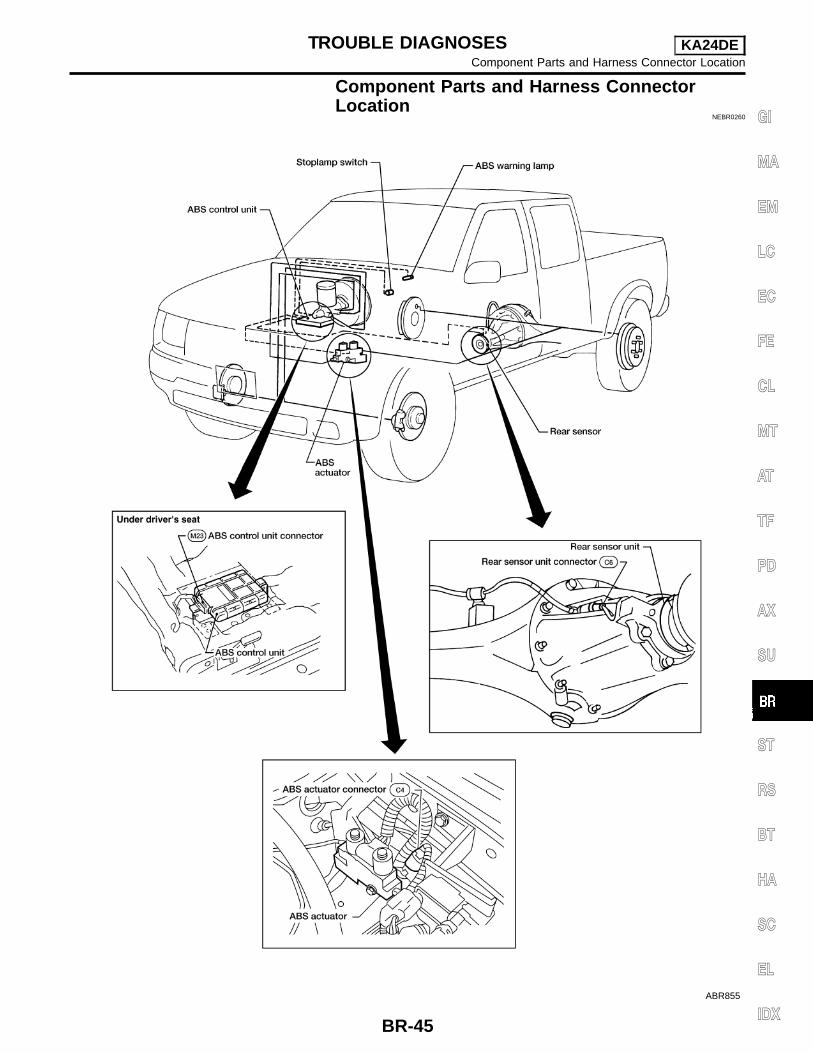
Component Parts and Harness ConnectorLocation
NEBR0260
ABR855
TROUBLE DIAGNOSES KA24DEComponent Parts and Harness Connector Location
BR-45
GI
MA
EM
LC
EC
FE
CL
MT
AT
TF
PD
AX
SU
ST
RS
BT
HA
SC
EL
IDX

SchematicNEBR0261
WBR363
TROUBLE DIAGNOSES KA24DESchematic
BR-46

Wiring Diagram — ABS —NEBR0262
WBR364
TROUBLE DIAGNOSES KA24DEWiring Diagram — ABS —
BR-47
GI
MA
EM
LC
EC
FE
CL
MT
AT
TF
PD
AX
SU
ST
RS
BT
HA
SC
EL
IDX

LBR094
TROUBLE DIAGNOSES KA24DEWiring Diagram — ABS — (Cont’d)
BR-48
Self-diagnosisNEBR0263
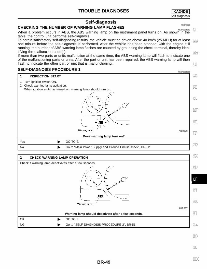
CHECKING THE NUMBER OF WARNING LAMP FLASHESNEBR0263S01
When a problem occurs in ABS, the ABS warning lamp on the instrument panel turns on. As shown in thetable, the control unit performs self-diagnosis.To obtain satisfactory self-diagnosing results, the vehicle must be driven above 40 km/h (25 MPH) for at leastone minute before the self-diagnosis is performed. After the vehicle has been stopped, with the engine stillrunning, the number of ABS warning lamp flashes are counted by grounding the check terminal, thereby iden-tifying the malfunction code(s).If more than two parts or units malfunction at the same time, the ABS warning lamp will flash to indicate oneof the malfunctioning parts or units. After the part or unit has been repaired, the ABS warning lamp will thenflash to indicate the other part or unit that is malfunctioning.
SELF-DIAGNOSIS PROCEDURE 1NEBR0263S02
1 INSPECTION START
1. Turn ignition switch ON.2. Check warning lamp activation.
When ignition switch is turned on, warning lamp should turn on.
ABR838
Does warning lamp turn on?
Yes GO TO 2.
No Go to “Main Power Supply and Ground Circuit Check”, BR-52.
2 CHECK WARNING LAMP OPERATION
Check if warning lamp deactivates after a few seconds.
ABR837
Warning lamp should deactivate after a few seconds.
OK GO TO 3.
NG Go to “SELF DIAGNOSIS PROCEDURE 2”, BR-51.
TROUBLE DIAGNOSES KA24DESelf-diagnosis
BR-49
GI
MA
EM
LC
EC
FE
CL
MT
AT
TF
PD
AX
SU
ST
RS
BT
HA
SC
EL
IDX

3 ROAD TEST
Drive vehicle above 40 km/h (25 MPH) for at least one minute.
ABR838
Does warning lamp activate again?
Yes Go to “SELF DIAGNOSIS PROCEDURE 2”, BR-51.
No GO TO 4.
4 CHECK ACTUATOR
1. Stop engine.2. Turn ignition switch ON.
Check actuator clicking noise when warning lamp deactivates.
ABR854
Actuator should make clicking noise when warning lamp deactivates.
OK INSPECTION END
NG Check actuator.Refer to “Electrical Components Inspection”, BR-65.
TROUBLE DIAGNOSES KA24DESelf-diagnosis (Cont’d)
BR-50
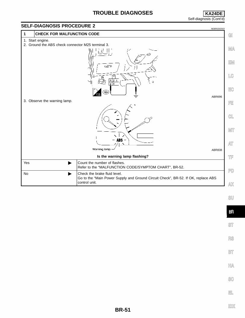
SELF-DIAGNOSIS PROCEDURE 2NEBR0263S03
1 CHECK FOR MALFUNCTION CODE
1. Start engine.2. Ground the ABS check connector M25 terminal 3.
ABR696
3. Observe the warning lamp.
ABR838
Is the warning lamp flashing?
Yes Count the number of flashes.Refer to the “MALFUNCTION CODE/SYMPTOM CHART”, BR-52.
No Check the brake fluid level.Go to the “Main Power Supply and Ground Circuit Check”, BR-52. If OK, replace ABScontrol unit.
TROUBLE DIAGNOSES KA24DESelf-diagnosis (Cont’d)
BR-51
GI
MA
EM
LC
EC
FE
CL
MT
AT
TF
PD
AX
SU
ST
RS
BT
HA
SC
EL
IDX

MALFUNCTION CODE/SYMPTOM CHART=NEBR0263S04
Code No./Symptom(No. of warning lamp flashes)
Malfunctioning part Diagnostic Procedure
2 Actuator ISO solenoid (open-circuit) BR-56
7 Actuator DUMP solenoid (open-circuit) BR-56
4 Actuator DUMP solenoid (short-circuit) BR-57
3 Actuator dump solenoid (open-circuit) BR-58
8 Actuator dump solenoid (short-circuit) BR-58
9 Rear sensor (open-circuit) BR-60
10 Rear sensor (short-circuit) BR-60
6 Sensor signal (erratic) BR-60
13
Control BR-6114
15
16 None (system OK) None
5 ABS actuator BR-61
Pedal vibration or noise — BR-62
Long stopping distance — BR-63
Brake pedal stroke is large — BR-63
ABS does not work — BR-64
ABS works frequently — BR-64
Main Power Supply and Ground Circuit CheckNEBR0264
1 CHECK WARNING LAMP POWER SUPPLY
1. Confirm battery voltage is 12V.2. Disconnect ABS control unit connector.3. Turn ignition switch ON.
LBR126
Do approx. 12 volts exist between ABS control unit connector M23 terminals 2 and 11?
Yes GO TO 2.
No GO TO 5.
TROUBLE DIAGNOSES KA24DESelf-diagnosis (Cont’d)
BR-52

2 CHECK ABS CONTROL UNIT POWER SUPPLY
1. Turn ignition switch ON.2. Do approx. 12 volts exist between ABS control unit connector M23 terminals (3, 12) and 11?
ABR625
Approx. 12 volts should exist.
OK GO TO 3.
NG GO TO 5.
3 CHECK STOP LAMP SWITCH POWER SUPPLY
1. Depress brake pedal.2. Do approx. 12 volts exist between ABS control unit connector M23 terminals 8 and 11?
ABR627
Approx. 12 volts should exist.
OK GO TO 4.
NG Adjust stop lamp switch, if necessary. Replace stop lamp switch or repair harness orconnectors, if necessary.
TROUBLE DIAGNOSES KA24DEMain Power Supply and Ground Circuit Check (Cont’d)
BR-53
GI
MA
EM
LC
EC
FE
CL
MT
AT
TF
PD
AX
SU
ST
RS
BT
HA
SC
EL
IDX

4 CHECK PARKING BRAKE SWITCH POWER SUPPLY
1. Confirm that brake fluid level is adequate.If necessary, refill it.
2. Start engine.3. Do approx. 12 volts exist between ABS control unit connector M23 terminals 5 and 11 without the parking brake
applied? Do approx. 0 volts exist with the parking brake applied?
ABR628
Yes or No?
Yes INSPECTION END
No Adjust parking brake switch, if necessary.Replace parking brake switch, or repair harness or connectors, if necessary.
5 CHECK FUSE
Check 10A fuse No. 11. For fuse layout refer to EL-9, “POWER SUPPLY ROUTING”.
Is fuse OK?
Yes GO TO 6.
No GO TO 7.
6 CHECK GROUND CIRCUIT
Check harness for continuity between ABS control unit connector M23 terminal 11 and ground.
ABR626
Does continuity exist?
Yes Check warning lamp and replace if necessary. If OK, check repair harness or connectors.
No Check and repair harness or connector between ABS control unit connector M23 termi-nal 11 and ground.
TROUBLE DIAGNOSES KA24DEMain Power Supply and Ground Circuit Check (Cont’d)
BR-54

7 REPLACE FUSE
Replace fuse.
Does the fuse blow out when the ignition switch is turned ON?
Yes Check and repair harness between ABS control unit connector M23 terminals (3, 12) andfuse block connector M26 terminal 3P (for fuse block details refer to EL-9, “POWERSUPPLY ROUTING”.
No INSPECTION END
TROUBLE DIAGNOSES KA24DEMain Power Supply and Ground Circuit Check (Cont’d)
BR-55
GI
MA
EM
LC
EC
FE
CL
MT
AT
TF
PD
AX
SU
ST
RS
BT
HA
SC
EL
IDX

ABS Actuator ISO Solenoid Short or OpenNEBR0265
MALFUNCTION CODE NO. 2 OR 7NEBR0265S01
1 CHECK ISO SOLENOID CIRCUITS
Disconnect battery cable ground connection.1. Disconnect ABS control unit connector.2. Check resistance between ABS control unit connector M23 terminals 1 and 11.
ABR629
Resistance should be approx. 4Ω
OK Replace ABS control unit.
NG GO TO 2.
2 CHECK ABS CONTROL UNIT GROUND CIRCUIT
Check ABS control unit ground circuit. Refer to “Main Power Supply and Ground Circuit Check”, BR-52.
OK or NG
OK GO TO 3.
NG Repair harness or connectors.
3 CHECK ABS ACTUATOR GROUND CIRCUIT
Check harness continuity between ABS actuator connector C4 terminal 2 and ground.
ABR630
Does continuity exist?
Yes GO TO 4.
No Repair ABS actuator harness or connectors.
TROUBLE DIAGNOSES FOR SELF-DIAGNOSTIC ITEMS KA24DEABS Actuator ISO Solenoid Short or Open
BR-56

4 CHECK ISO SOLENOID
Check resistance between ABS actuator connector C4 terminals 2 and 3.
ABR631
Resistance should be approx. 4Ω
OK Repair harness and connectors between the ISO solenoid and ABS control unit.
NG Replace ABS actuator.
ABS Actuator ISO BlockedNEBR0266
MALFUNCTION CODE NO. 4NEBR0266S01
1 CHECK ABS ACTUATOR SWITCH
Disconnect battery cable ground connection.1. Disconnect ABS control unit connector.2. Check for continuity between ABS control unit connector M23 terminal 4 and ground.
ABR632
Continuity should not exist.
OK Replace ABS control unit.
NG GO TO 2.
TROUBLE DIAGNOSES FOR SELF-DIAGNOSTIC ITEMS KA24DEABS Actuator ISO Solenoid Short or Open (Cont’d)
BR-57
GI
MA
EM
LC
EC
FE
CL
MT
AT
TF
PD
AX
SU
ST
RS
BT
HA
SC
EL
IDX

2 CHECK ABS ACTUATOR CIRCUIT
1. Disconnect ABS actuator connector.2. Check for continuity between ABS actuator connector C4 terminal 4 and ground.
ABR787
Continuity should not exist.
OK Repair harness or connectors between ABS control unit and ABS actuator.
NG Replace ABS actuator.
ABS Actuator Dump Solenoid Short Circuit orOpen
NEBR0267
MALFUNCTION CODE NO. 3 OR 8NEBR0267S01
1 CHECK DUMP SOLENOID
Disconnect battery cable ground connection.1. Disconnect ABS control unit connector.2. Check resistance between ABS control unit connector M23 terminals 11 and 17.
ABR634
Resistance should be approx. 1.5Ω
OK Replace ABS control unit.
NG GO TO 2.
2 CHECK ABS CONTROL UNIT GROUND CIRCUIT
Refer to “Main Power Supply and Ground Circuit Check”, BR-52.
OK or NG
OK GO TO 3.
NG Repair harness or connectors.
TROUBLE DIAGNOSES FOR SELF-DIAGNOSTIC ITEMS KA24DEABS Actuator ISO Blocked (Cont’d)
BR-58
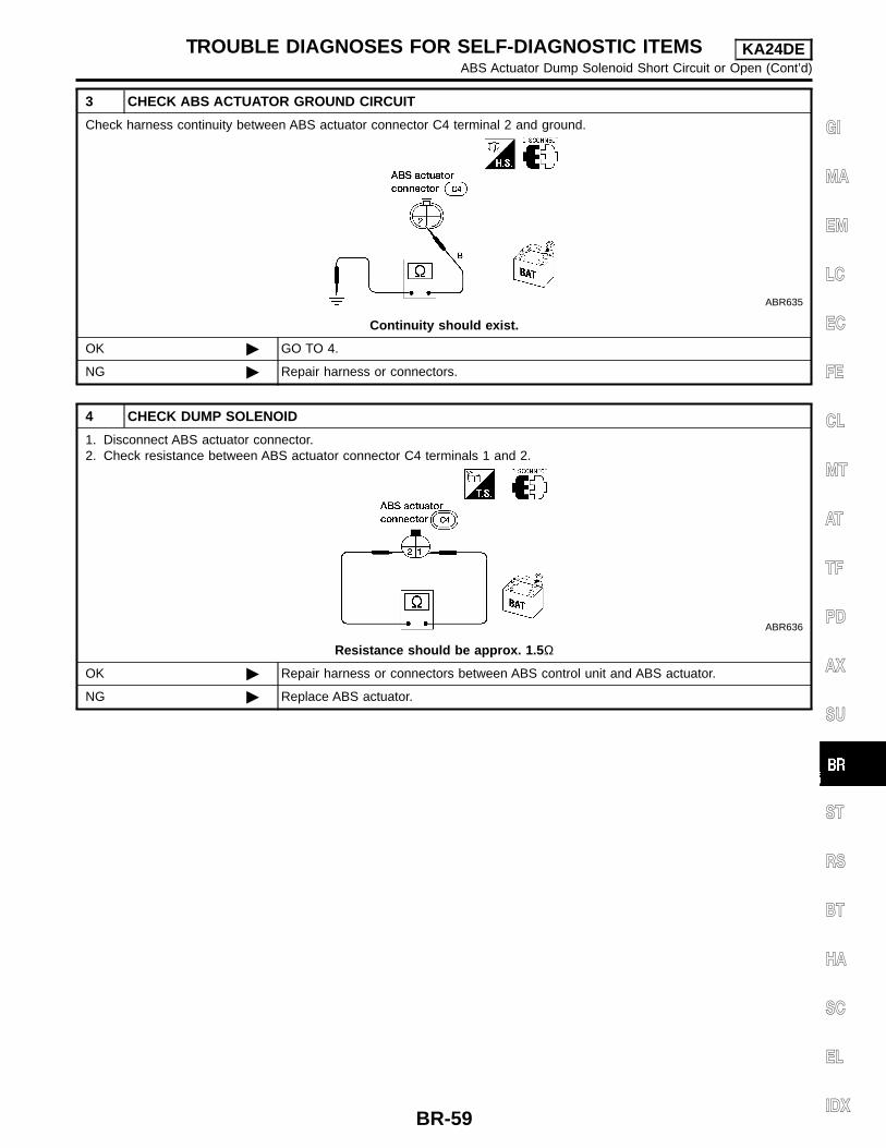
3 CHECK ABS ACTUATOR GROUND CIRCUIT
Check harness continuity between ABS actuator connector C4 terminal 2 and ground.
ABR635
Continuity should exist.
OK GO TO 4.
NG Repair harness or connectors.
4 CHECK DUMP SOLENOID
1. Disconnect ABS actuator connector.2. Check resistance between ABS actuator connector C4 terminals 1 and 2.
ABR636
Resistance should be approx. 1.5Ω
OK Repair harness or connectors between ABS control unit and ABS actuator.
NG Replace ABS actuator.
TROUBLE DIAGNOSES FOR SELF-DIAGNOSTIC ITEMS KA24DEABS Actuator Dump Solenoid Short Circuit or Open (Cont’d)
BR-59
GI
MA
EM
LC
EC
FE
CL
MT
AT
TF
PD
AX
SU
ST
RS
BT
HA
SC
EL
IDX
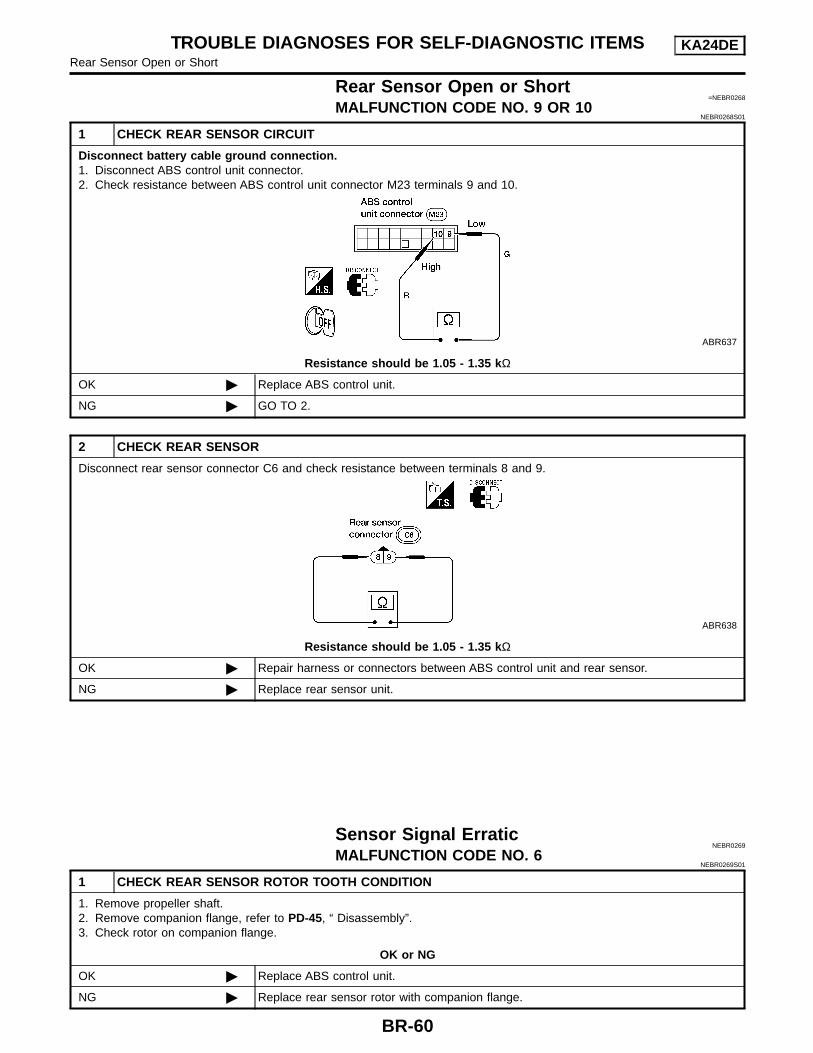
Rear Sensor Open or Short=NEBR0268
MALFUNCTION CODE NO. 9 OR 10NEBR0268S01
1 CHECK REAR SENSOR CIRCUIT
Disconnect battery cable ground connection.1. Disconnect ABS control unit connector.2. Check resistance between ABS control unit connector M23 terminals 9 and 10.
ABR637
Resistance should be 1.05 - 1.35 kΩ
OK Replace ABS control unit.
NG GO TO 2.
2 CHECK REAR SENSOR
Disconnect rear sensor connector C6 and check resistance between terminals 8 and 9.
ABR638
Resistance should be 1.05 - 1.35 kΩ
OK Repair harness or connectors between ABS control unit and rear sensor.
NG Replace rear sensor unit.
Sensor Signal ErraticNEBR0269
MALFUNCTION CODE NO. 6NEBR0269S01
1 CHECK REAR SENSOR ROTOR TOOTH CONDITION
1. Remove propeller shaft.2. Remove companion flange, refer to PD-45, “ Disassembly”.3. Check rotor on companion flange.
OK or NG
OK Replace ABS control unit.
NG Replace rear sensor rotor with companion flange.
TROUBLE DIAGNOSES FOR SELF-DIAGNOSTIC ITEMS KA24DERear Sensor Open or Short
BR-60

ABS Control Unit=NEBR0270
MALFUNCTION CODE NO. 13, 14 OR 15NEBR0270S01
There has been an ABS control unit malfunction.Replace ABS control unit.
ABS ActuatorNEBR0271
MALFUNCTION CODE NO. 5NEBR0271S01
1 CHECK BRAKE SYSTEM
Overhaul both rear brakes.1. Refer to “SELF-DIAGNOSIS PROCEDURE 1”, BR-492. Check if ABS system is OK.
OK or NG
OK INSPECTION END
NG GO TO 2.
2 CHECK FOR MALFUNCTION CODES
Does warning lamp still flash malfunction code No. 5?
Yes or No
Yes Replace ABS actuator.
No Inspect ABS system, referring to warning flashes.
TROUBLE DIAGNOSES FOR SELF-DIAGNOSTIC ITEMS KA24DEABS Control Unit
BR-61
GI
MA
EM
LC
EC
FE
CL
MT
AT
TF
PD
AX
SU
ST
RS
BT
HA
SC
EL
IDX

1. Pedal Vibration or NoiseNEBR0272
1 INSPECTION START
Pedal vibration and noise inspection
SAT797A
GO TO 2.
2 CHECK SYMPTOM
1. Apply brake.2. Start engine.
Does the symptom appear only when engine is started?
Yes Carry out “Self-diagnosis”. Refer to BR-49.
No Go to Test No. 3, “3. Unexpected Pedal Action”, BR-64.
NOTE:ABS may operate and cause vibration under any of the followingconditions. Applying brake gradually when shifting or operating clutch. Low friction (slippery) road. High speed cornering. Driving over bumps and potholes. Engine speed is over 5,000 rpm with vehicle stopped.
TROUBLE DIAGNOSES FOR SYMPTOMS KA24DE1. Pedal Vibration or Noise
BR-62

2. Long Stopping Distance=NEBR0273
1 CHECK MECHANICAL BRAKE SYSTEM PERFORMANCE
Disconnect ABS actuator connector and check whether stopping distance is still long.
Does brake system function properly when brake pedal is depressed?
Yes Perform “Preliminary Check”, BR-42 and “Bleeding Brake System”, BR-11 (if necessary).
No Go to Test No. 3, “3. Unexpected Pedal Action”, BR-64.
NOTE:Stopping distance may be longer for vehicles without ABS whenroad condition is slippery.
3. Unexpected Pedal ActionNEBR0274
1 CHECK BRAKE PEDAL STROKE
Check brake pedal stroke.
SBR540A
Is brake pedal stroke excessively large?
Yes Perform “Preliminary Check”, refer to BR-42.
No GO TO 2.
2 CHECK MECHANICAL BRAKE SYSTEM PERFORMANCE
Disconnect ABS actuator connector and check whether brake is effective.
Does brake system function properly when brake pedal is depressed?
Yes GO TO 3.
No Perform “Preliminary Check”, refer to BR-42.
TROUBLE DIAGNOSES FOR SYMPTOMS KA24DE2. Long Stopping Distance
BR-63
GI
MA
EM
LC
EC
FE
CL
MT
AT
TF
PD
AX
SU
ST
RS
BT
HA
SC
EL
IDX

3 CHECK WARNING LAMP INDICATION
Ensure warning lamp remains off while driving.
ABR837
Is warning lamp turned off?
Yes GO TO 4.
No Carry out “Self-diagnosis”, refer to BR-49.
4 CHECK REAR SENSOR
1. Check rear sensor connector for terminal damage or loose connection.2. Perform rear sensor check. Refer to Test No. 2, “MALFUNCTION CODE NO. 9 OR 10”, BR-60.
Is rear sensor OK?
Yes Check ABS actuator terminals for damage or the connection of ABS actuator harnessconnector.Reconnect ABS actuator harness connector.Then retest.
No Repair or replace as necessary.
4. ABS Does Not WorkNEBR0275
1 CHECK WARNING LAMP INDICATION
Does the ABS warning lamp activate?
Yes or No
Yes Carry out “Self-diagnosis”. Refer to BR-49.
No Go to “SELF-DIAGNOSIS PROCEDURE 1”, BR-49.
NOTE:ABS does not work when vehicle speed is under 10 km/h (6 MPH).
5. ABS Works FrequentlyNEBR0276
1 CHECK BRAKE FLUID PRESSURE
Check brake fluid pressure distribution.Refer to “Inspection”, BR-14.
Is brake fluid pressure distribution normal?
Yes GO TO 2.
No Repair. Then perform “Preliminary Check”, refer to BR-42.
TROUBLE DIAGNOSES FOR SYMPTOMS KA24DE3. Unexpected Pedal Action (Cont’d)
BR-64

2 CHECK WHEEL SENSOR
1. Check rear sensor connector for terminal damage or loose connections.2. Refer to “Rear Sensor Open or Short”, BR-60.
Is rear sensor OK?
Yes Check ABS actuator terminals for damage or the connection of ABS actuator harnessconnector.Reconnect ABS actuator harness connector.Then retest.
No Repair or replace as necessary.
Electrical Components InspectionNEBR0277
REAR SENSOR UNIT AND ACTUATORNEBR0277S01
1 CHECK REAR SENSOR SIGNAL
1. Raise vehicle. Confirm it is safe to rotate rear wheels.
SBR373D
2. Start engine and rotate rear wheels with transmission in D position or first gear position.3. Check rear sensor voltage between ABS control unit connector M23 terminals 9 and 10 with voltmeter set to AC volt-
age scale.
ABR639
NOTE:A/T at 850 rpmNOTE:M/T at 700 rpm
Voltage should be 0.4V or higher.
OK GO TO 2.
NG GO TO 4.
TROUBLE DIAGNOSES FOR SYMPTOMS KA24DE5. ABS Works Frequently (Cont’d)
BR-65
GI
MA
EM
LC
EC
FE
CL
MT
AT
TF
PD
AX
SU
ST
RS
BT
HA
SC
EL
IDX
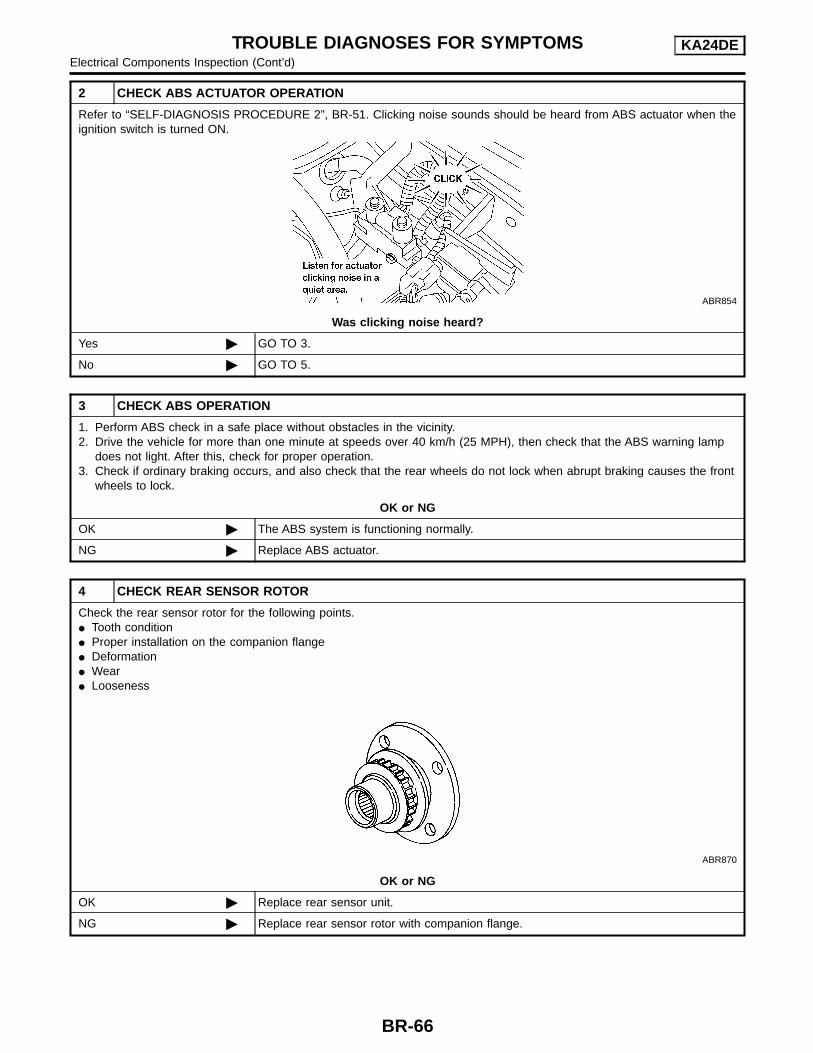
2 CHECK ABS ACTUATOR OPERATION
Refer to “SELF-DIAGNOSIS PROCEDURE 2”, BR-51. Clicking noise sounds should be heard from ABS actuator when theignition switch is turned ON.
ABR854
Was clicking noise heard?
Yes GO TO 3.
No GO TO 5.
3 CHECK ABS OPERATION
1. Perform ABS check in a safe place without obstacles in the vicinity.2. Drive the vehicle for more than one minute at speeds over 40 km/h (25 MPH), then check that the ABS warning lamp
does not light. After this, check for proper operation.3. Check if ordinary braking occurs, and also check that the rear wheels do not lock when abrupt braking causes the front
wheels to lock.
OK or NG
OK The ABS system is functioning normally.
NG Replace ABS actuator.
4 CHECK REAR SENSOR ROTOR
Check the rear sensor rotor for the following points. Tooth condition Proper installation on the companion flange Deformation Wear Looseness
ABR870
OK or NG
OK Replace rear sensor unit.
NG Replace rear sensor rotor with companion flange.
TROUBLE DIAGNOSES FOR SYMPTOMS KA24DEElectrical Components Inspection (Cont’d)
BR-66
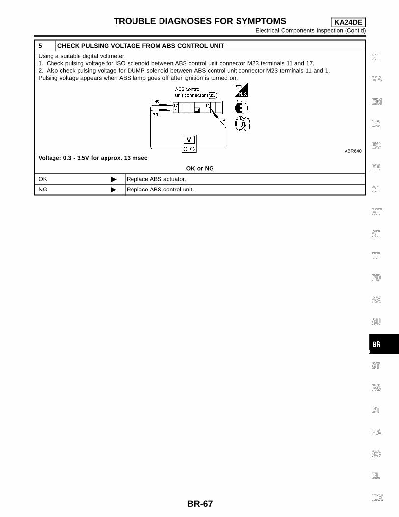
5 CHECK PULSING VOLTAGE FROM ABS CONTROL UNIT
Using a suitable digital voltmeter1. Check pulsing voltage for ISO solenoid between ABS control unit connector M23 terminals 11 and 17.2. Also check pulsing voltage for DUMP solenoid between ABS control unit connector M23 terminals 11 and 1.Pulsing voltage appears when ABS lamp goes off after ignition is turned on.
ABR640
Voltage: 0.3 - 3.5V for approx. 13 msec
OK or NG
OK Replace ABS actuator.
NG Replace ABS control unit.
TROUBLE DIAGNOSES FOR SYMPTOMS KA24DEElectrical Components Inspection (Cont’d)
BR-67
GI
MA
EM
LC
EC
FE
CL
MT
AT
TF
PD
AX
SU
ST
RS
BT
HA
SC
EL
IDX
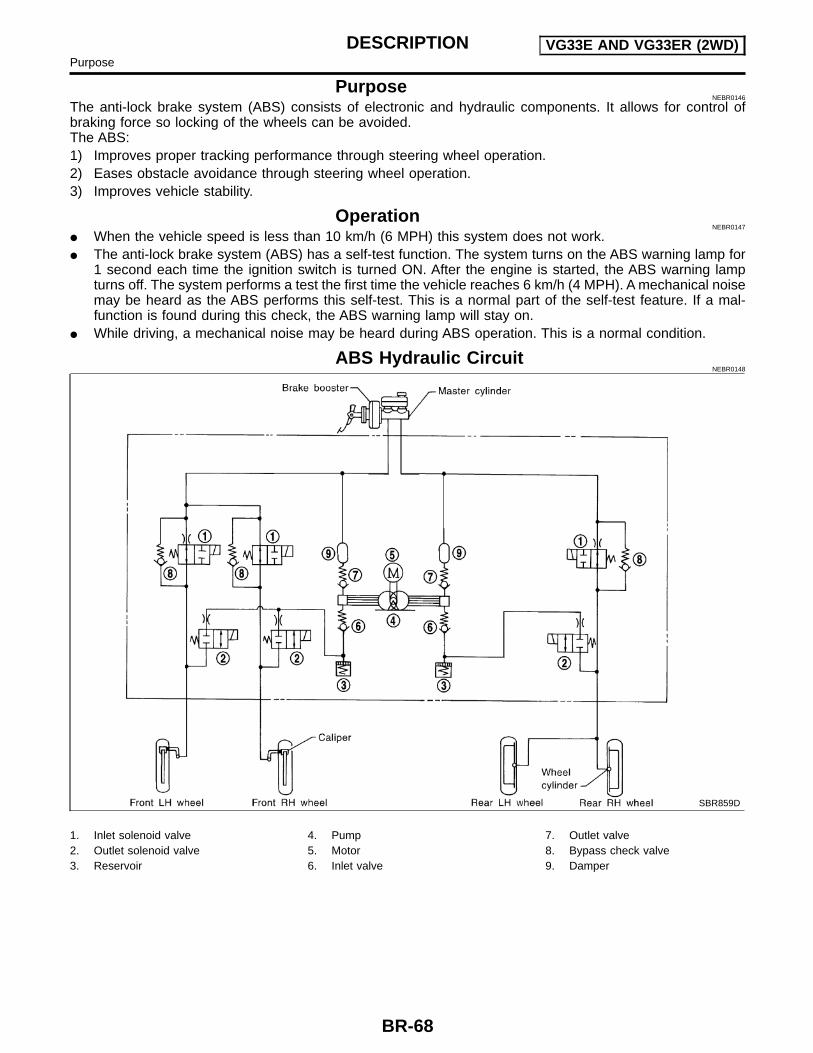
PurposeNEBR0146
The anti-lock brake system (ABS) consists of electronic and hydraulic components. It allows for control ofbraking force so locking of the wheels can be avoided.The ABS:1) Improves proper tracking performance through steering wheel operation.2) Eases obstacle avoidance through steering wheel operation.3) Improves vehicle stability.
OperationNEBR0147
When the vehicle speed is less than 10 km/h (6 MPH) this system does not work. The anti-lock brake system (ABS) has a self-test function. The system turns on the ABS warning lamp for
1 second each time the ignition switch is turned ON. After the engine is started, the ABS warning lampturns off. The system performs a test the first time the vehicle reaches 6 km/h (4 MPH). A mechanical noisemay be heard as the ABS performs this self-test. This is a normal part of the self-test feature. If a mal-function is found during this check, the ABS warning lamp will stay on.
While driving, a mechanical noise may be heard during ABS operation. This is a normal condition.
ABS Hydraulic CircuitNEBR0148
SBR859D
1. Inlet solenoid valve2. Outlet solenoid valve3. Reservoir
4. Pump5. Motor6. Inlet valve
7. Outlet valve8. Bypass check valve9. Damper
DESCRIPTION VG33E AND VG33ER (2WD)Purpose
BR-68

System ComponentsNEBR0149
LBR125
DESCRIPTION VG33E AND VG33ER (2WD)System Components
BR-69
GI
MA
EM
LC
EC
FE
CL
MT
AT
TF
PD
AX
SU
ST
RS
BT
HA
SC
EL
IDX

SBR124B
System Description=NEBR0150
WHEEL SENSORNEBR0150S01
The sensor unit consists of a gear-shaped sensor rotor and a sen-sor element. The element contains a bar magnet around which acoil is wound. The front sensors are installed on the back of thebrake rotors and the rear sensor is installed on the differential. Asthe wheel rotates, the sensor generates a sine-wave pattern. Thefrequency and voltage increase(s) as the rotating speed increases.
SBR071E
ABS ACTUATOR AND ELECTRIC UNIT (CONTROLUNIT)
NEBR0150S02
The ABS actuator and electric unit (control unit) computes thewheel rotating speed by the signal current sent from the sensor.Then it supplies a DC current to the actuator solenoid valve. It alsocontrols ON-OFF operation of the valve relay and motor relay. Ifany electrical malfunction should be detected in the system, thecontrol unit causes the warning lamp to light up. In this condition,the ABS will be deactivated by the control unit, and the vehicle’sbrake system reverts to normal operation.The ABS actuator and electric unit (control unit) contains: An electric motor and pump Two relays Six solenoid valves, each inlet and outlet for
— LH front— RH front— Rear
ABS control unitThis component controls the hydraulic circuit and increases, holdsor decreases hydraulic pressure to all or individual wheels. TheABS actuator and electric unit is serviced as an assembly.
ABS Actuator OperationNEBR0150S0201
Inlet solenoidvalve
Outlet solenoidvalve
Normal brake operation OFF (Open) OFF (Closed)Master cylinder brake fluid pressure is directly trans-mitted to caliper via the inlet solenoid valve.
ABS operation
Pressure hold ON (Closed) OFF (Closed)Hydraulic circuit is shut off to hold the caliper brakefluid pressure.
Pressuredecrease
ON (Closed) ON (Open)Caliper and wheel cylinder brake fluid is sent to reser-voir via the outlet solenoid valve. Then it is pushed upto the master cylinder by pump.
Pressureincrease
OFF (Open) OFF (Closed)Master cylinder brake fluid pressure is transmitted tocaliper.
DESCRIPTION VG33E AND VG33ER (2WD)System Description
BR-70

Removal and Installation=NEBR0174
FRONT WHEEL SENSORSNEBR0174S01
CAUTION:Be careful not to damage sensor edge and sensor rotor teeth.When removing the front wheel hub or rear axle shaftassembly, disconnect and remove the ABS wheel sensor fromthe assembly and move it away.
ABR869
REAR WHEEL SENSORNEBR0174S02
LBR116
DESCRIPTION VG33E AND VG33ER (2WD)Removal and Installation
BR-71
GI
MA
EM
LC
EC
FE
CL
MT
AT
TF
PD
AX
SU
ST
RS
BT
HA
SC
EL
IDX

ABS ACTUATOR AND ELECTRIC UNITNEBR0174S04
ABR704
RemovalNEBR0174S0402
1) Disconnect battery cable.2) Drain brake fluid. Refer to “Changing Brake Fluid”, BR-9.3) Disconnect ABS actuator and electric unit (control unit connec-
tor) and brake pipes.4) Remove mounting bracket fixing bolts and nuts.
InstallationNEBR0174S0403
CAUTION:After installation, refill brake fluid. Then bleed air. Refer to“Bleeding Brake System”, BR-11.1) Connect brake pipes temporarily.2) Tighten fixing bolts and nuts.3) Tighten brake pipes.4) Connect connector and battery cable.
DESCRIPTION VG33E AND VG33ER (2WD)Removal and Installation (Cont’d)
BR-72

SEF233G
SEF234G
How to Perform Trouble Diagnoses for Quickand Accurate Repair
NEBR0176
INTRODUCTIONNEBR0176S01
The ABS system has an electronic control unit to control majorfunctions. The control unit accepts input signals from sensors andinstantly drives the actuators. It is essential that both kinds of sig-nals are proper and stable. It is also important to check for conven-tional problems such as air leaks in booster lines, lack of brakefluid, or other problems with the brake system.It is much more difficult to diagnose a problem that occurs intermit-tently rather than continuously. Most intermittent problems arecaused by poor electric connection or faulty wiring. In this case,careful checking of suspicious circuits may help prevent thereplacement of good parts.A visual check only may not find the cause of the problems, so aroad test should be performed.Before undertaking actual checks, take a few minutes to talk witha customer who approaches with an ABS complaint. The customeris a very good source of information on such problems; especiallyintermittent ones. Through the talks with the customer, find outwhat symptoms are present and under what conditions they occur.Start your diagnosis by looking for “conventional” problems first.This is one of the best ways to troubleshoot brake problems on anABS controlled vehicle.Also check related Service bulletins for information.
TROUBLE DIAGNOSES VG33E AND VG33ER (2WD)How to Perform Trouble Diagnoses for Quick and Accurate Repair
BR-73
GI
MA
EM
LC
EC
FE
CL
MT
AT
TF
PD
AX
SU
ST
RS
BT
HA
SC
EL
IDX
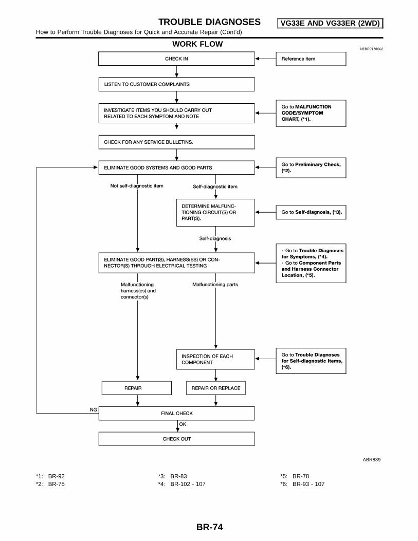
WORK FLOWNEBR0176S02
ABR839
*1: BR-92*2: BR-75
*3: BR-83*4: BR-102 - 107
*5: BR-78*6: BR-93 - 107
TROUBLE DIAGNOSES VG33E AND VG33ER (2WD)How to Perform Trouble Diagnoses for Quick and Accurate Repair (Cont’d)
BR-74
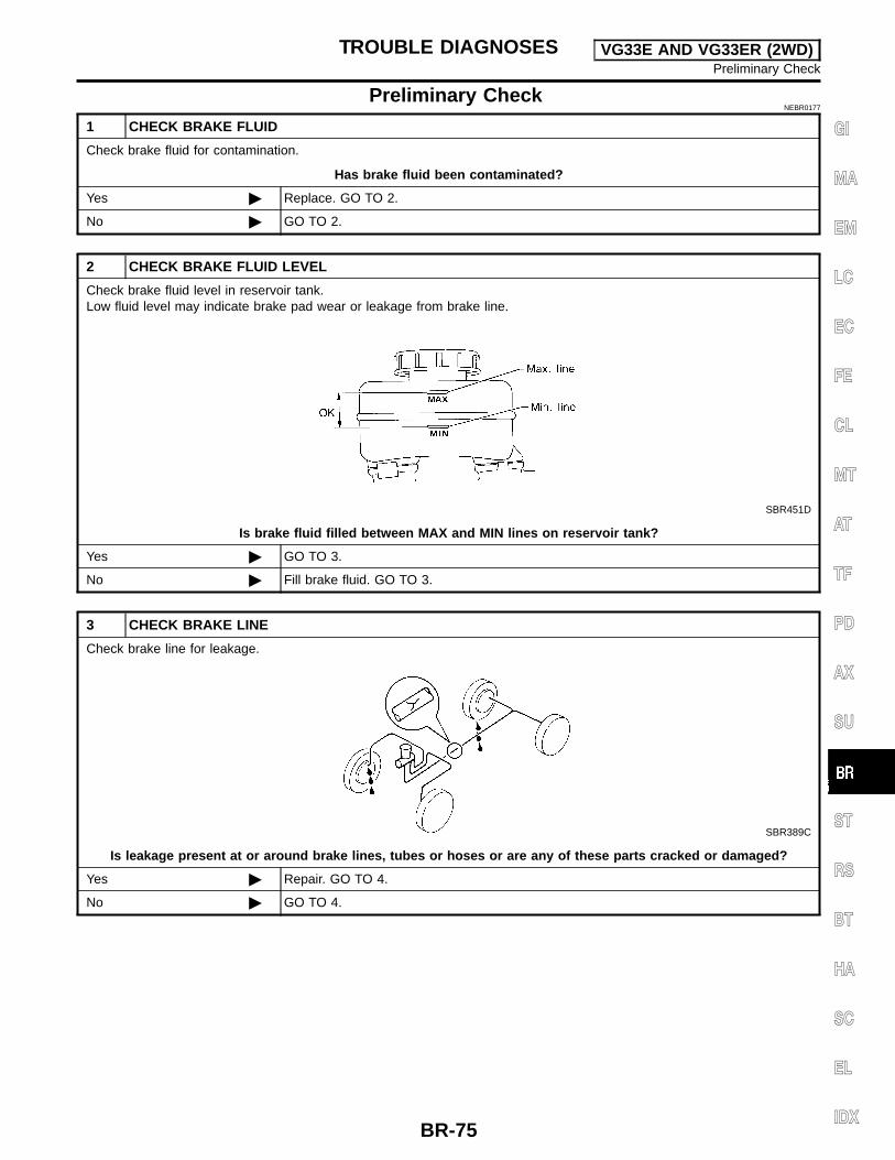
Preliminary CheckNEBR0177
1 CHECK BRAKE FLUID
Check brake fluid for contamination.
Has brake fluid been contaminated?
Yes Replace. GO TO 2.
No GO TO 2.
2 CHECK BRAKE FLUID LEVEL
Check brake fluid level in reservoir tank.Low fluid level may indicate brake pad wear or leakage from brake line.
SBR451D
Is brake fluid filled between MAX and MIN lines on reservoir tank?
Yes GO TO 3.
No Fill brake fluid. GO TO 3.
3 CHECK BRAKE LINE
Check brake line for leakage.
SBR389C
Is leakage present at or around brake lines, tubes or hoses or are any of these parts cracked or damaged?
Yes Repair. GO TO 4.
No GO TO 4.
TROUBLE DIAGNOSES VG33E AND VG33ER (2WD)Preliminary Check
BR-75
GI
MA
EM
LC
EC
FE
CL
MT
AT
TF
PD
AX
SU
ST
RS
BT
HA
SC
EL
IDX
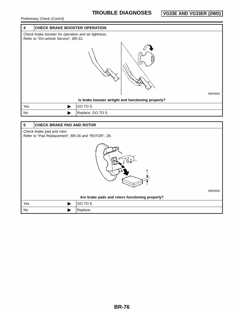
4 CHECK BRAKE BOOSTER OPERATION
Check brake booster for operation and air tightness.Refer to “On-vehicle Service”, BR-22.
SBR058C
Is brake booster airtight and functioning properly?
Yes GO TO 5.
No Replace. GO TO 5.
5 CHECK BRAKE PAD AND ROTOR
Check brake pad and rotor.Refer to “Pad Replacement”, BR-26 and “ROTOR”, 28.
SBR059C
Are brake pads and rotors functioning properly?
Yes GO TO 6.
No Replace.
TROUBLE DIAGNOSES VG33E AND VG33ER (2WD)Preliminary Check (Cont’d)
BR-76

6 RECHECK BRAKE FLUID LEVEL
Check brake fluid level in reservoir tank again.
SBR451D
Is brake fluid filled between MAX and MIN lines on reservoir tank?
Yes GO TO 7.
No Fill brake fluid.
7 CHECK WARNING LAMP ACTIVATION
Check warning lamp activation.
ABR838
Does warning lamp turn on when ignition switch is turned ON?
Yes GO TO 8.
No Check fuse, warning lamp bulb and warning lamp circuit.
8 CHECK WARNING LAMP DEACTIVATION
Check warning lamp for deactivation after engine is started.
Does warning lamp turn off when engine is started?
Yes GO TO 9.
No Go to “Self-diagnosis”, BR-83.
9 DRIVE VEHICLE
Drive vehicle at speeds over 30 km/h (19 MPH) for at least one minute.
Does warning lamp remain off after vehicle has been driven at 30 km/h (19 MPH) for at least one minute?
Yes INSPECTION END
No Go to “Self-diagnosis”, BR-83.
TROUBLE DIAGNOSES VG33E AND VG33ER (2WD)Preliminary Check (Cont’d)
BR-77
GI
MA
EM
LC
EC
FE
CL
MT
AT
TF
PD
AX
SU
ST
RS
BT
HA
SC
EL
IDX
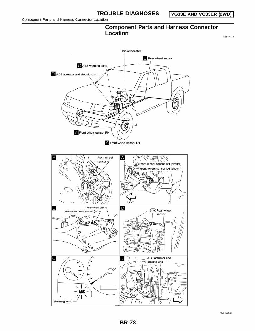
Component Parts and Harness ConnectorLocation
NEBR0178
WBR331
TROUBLE DIAGNOSES VG33E AND VG33ER (2WD)Component Parts and Harness Connector Location
BR-78
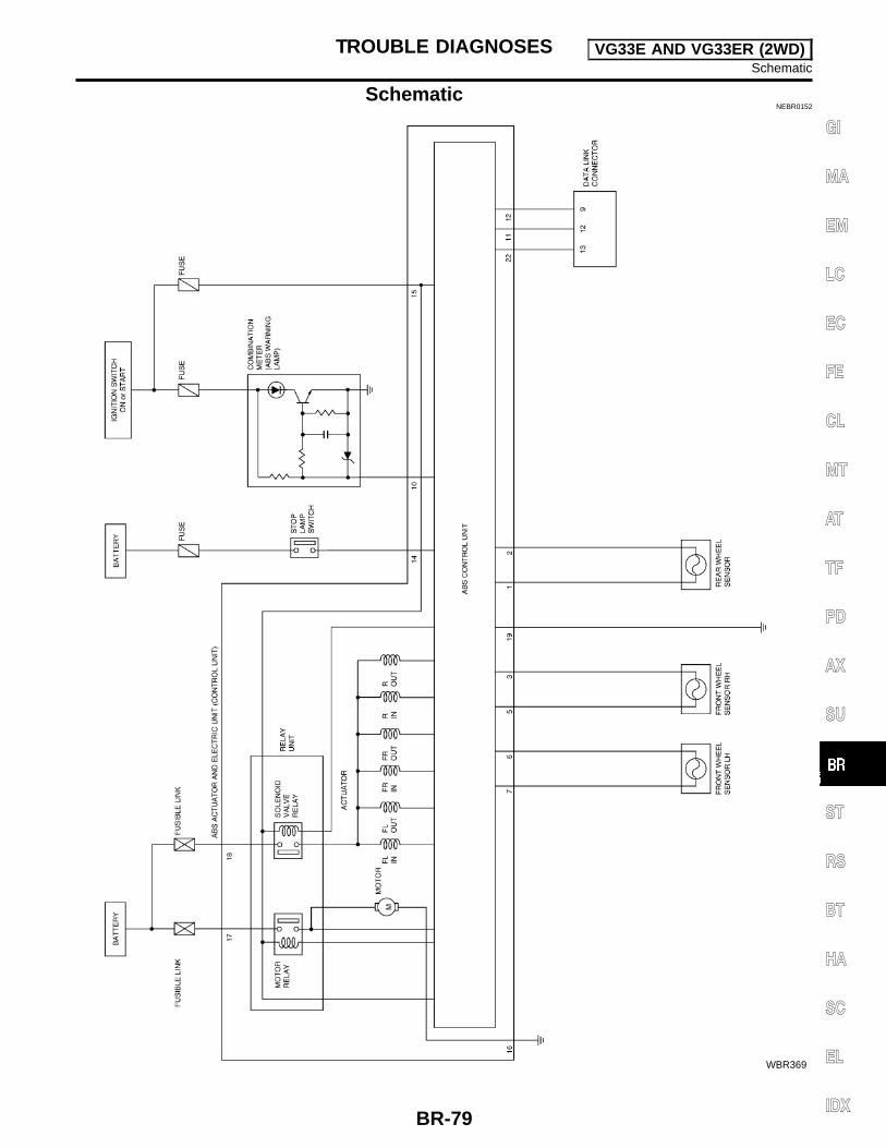
SchematicNEBR0152
WBR369
TROUBLE DIAGNOSES VG33E AND VG33ER (2WD)Schematic
BR-79
GI
MA
EM
LC
EC
FE
CL
MT
AT
TF
PD
AX
SU
ST
RS
BT
HA
SC
EL
IDX

Wiring Diagram — ABS —NEBR0153
LBR096
TROUBLE DIAGNOSES VG33E AND VG33ER (2WD)Wiring Diagram — ABS —
BR-80

WBR370
TROUBLE DIAGNOSES VG33E AND VG33ER (2WD)Wiring Diagram — ABS — (Cont’d)
BR-81
GI
MA
EM
LC
EC
FE
CL
MT
AT
TF
PD
AX
SU
ST
RS
BT
HA
SC
EL
IDX

WBR163
TROUBLE DIAGNOSES VG33E AND VG33ER (2WD)Wiring Diagram — ABS — (Cont’d)
BR-82

Self-diagnosisNEBR0154
FUNCTIONNEBR0154S01
When a problem occurs in the ABS, the warning lamp on theinstrument panel comes on. To start the self-diagnostic resultsmode, ground the self-diagnostic (check) terminal located ondata link connector. The location of the malfunction is indicatedby the warning lamp flashing.
SELF-DIAGNOSIS PROCEDURENEBR0154S02
1. Drive vehicle over 30 km/h (19 MPH) for at least one minute.2. Turn ignition switch OFF.
ABR847
3. Ground terminal 9 of data link connector with a suitable har-ness.
4. Turn ignition switch ON while grounding terminal 9.Do not depress brake pedal.
ABR916
5. After 3.0 seconds, the warning lamp starts flashing to indicatethe malfunction code No. (See NOTE.)
6. Verify the location of the malfunction with the “MalfunctionCode/Symptom Chart”, refer to BR-92. Then make the neces-sary repairs following the diagnostic procedures.
7. After the malfunctions are repaired, erase the malfunctioncodes stored in the control unit. Refer to “HOW TO ERASESELF-DIAGNOSTIC RESULTS (MALFUNCTION CODES)”,BR-84.
8. Rerun the self-diagnostic results mode to verify that the mal-function codes have been erased.
ABR847
9. Disconnect the check terminal from the ground. The self-diag-nostic results mode is now complete.
10. Check warning lamp for deactivation after driving vehicle over30 km/h (19 MPH) for at least one minute.
11. After making certain that warning lamp does not come on, testthe ABS in a safe area to verify that it functions properly.
NOTE:The indication terminates after 5 minutes.However, when the ignition switch is turned from OFF to ON, theindication starts flashing again.
ON BOARD DIAGNOSTIC SYSTEMDESCRIPTION VG33E AND VG33ER (2WD)
Self-diagnosis
BR-83
GI
MA
EM
LC
EC
FE
CL
MT
AT
TF
PD
AX
SU
ST
RS
BT
HA
SC
EL
IDX
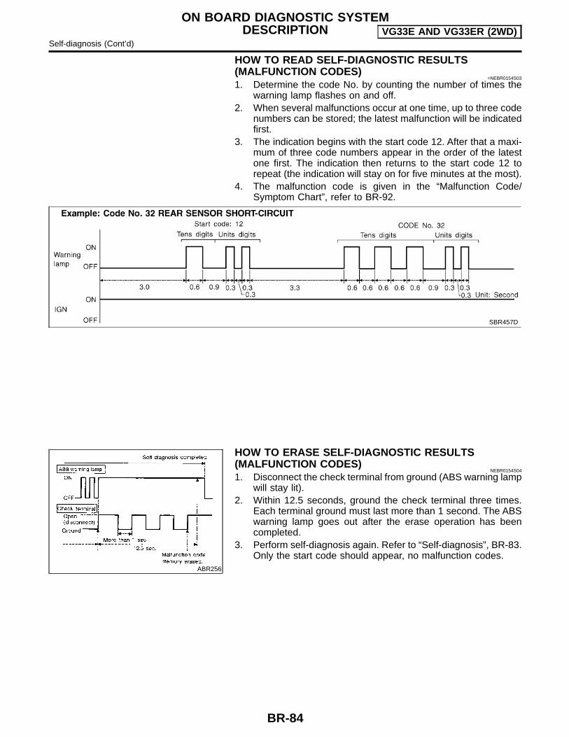
HOW TO READ SELF-DIAGNOSTIC RESULTS(MALFUNCTION CODES)
=NEBR0154S03
1. Determine the code No. by counting the number of times thewarning lamp flashes on and off.
2. When several malfunctions occur at one time, up to three codenumbers can be stored; the latest malfunction will be indicatedfirst.
3. The indication begins with the start code 12. After that a maxi-mum of three code numbers appear in the order of the latestone first. The indication then returns to the start code 12 torepeat (the indication will stay on for five minutes at the most).
4. The malfunction code is given in the “Malfunction Code/Symptom Chart”, refer to BR-92.
SBR457D
ABR256
HOW TO ERASE SELF-DIAGNOSTIC RESULTS(MALFUNCTION CODES)
NEBR0154S04
1. Disconnect the check terminal from ground (ABS warning lampwill stay lit).
2. Within 12.5 seconds, ground the check terminal three times.Each terminal ground must last more than 1 second. The ABSwarning lamp goes out after the erase operation has beencompleted.
3. Perform self-diagnosis again. Refer to “Self-diagnosis”, BR-83.Only the start code should appear, no malfunction codes.
ON BOARD DIAGNOSTIC SYSTEMDESCRIPTION VG33E AND VG33ER (2WD)
Self-diagnosis (Cont’d)
BR-84
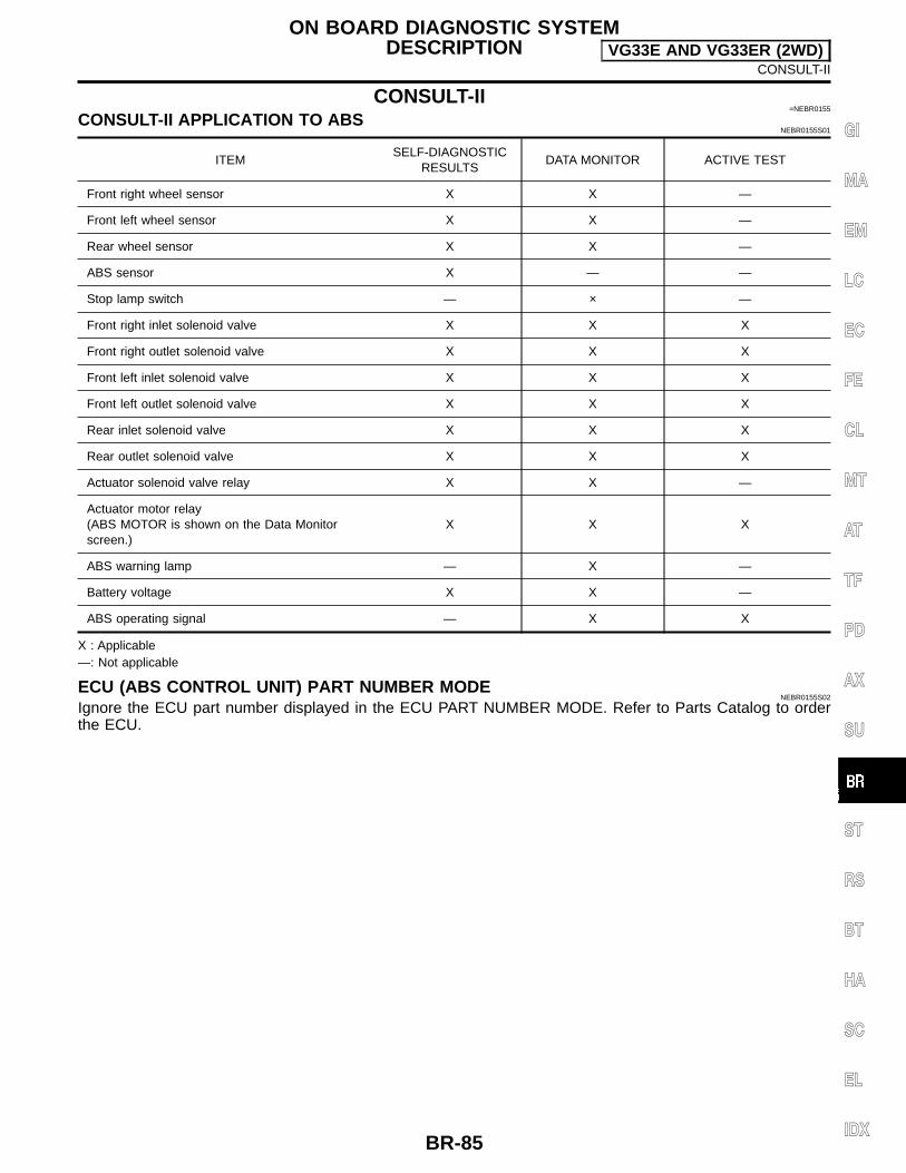
CONSULT-II=NEBR0155
CONSULT-II APPLICATION TO ABSNEBR0155S01
ITEMSELF-DIAGNOSTIC
RESULTSDATA MONITOR ACTIVE TEST
Front right wheel sensor X X —
Front left wheel sensor X X —
Rear wheel sensor X X —
ABS sensor X — —
Stop lamp switch — × —
Front right inlet solenoid valve X X X
Front right outlet solenoid valve X X X
Front left inlet solenoid valve X X X
Front left outlet solenoid valve X X X
Rear inlet solenoid valve X X X
Rear outlet solenoid valve X X X
Actuator solenoid valve relay X X —
Actuator motor relay(ABS MOTOR is shown on the Data Monitorscreen.)
X X X
ABS warning lamp — X —
Battery voltage X X —
ABS operating signal — X X
X : Applicable—: Not applicable
ECU (ABS CONTROL UNIT) PART NUMBER MODENEBR0155S02
Ignore the ECU part number displayed in the ECU PART NUMBER MODE. Refer to Parts Catalog to orderthe ECU.
ON BOARD DIAGNOSTIC SYSTEMDESCRIPTION VG33E AND VG33ER (2WD)
CONSULT-II
BR-85
GI
MA
EM
LC
EC
FE
CL
MT
AT
TF
PD
AX
SU
ST
RS
BT
HA
SC
EL
IDX

ABR847
CONSULT-II Inspection Procedure=NEBR0156
SELF-DIAGNOSIS PROCEDURENEBR0156S01
1. Turn ignition switch OFF.2. Connect CONSULT-II to data link connector.3. Start engine.4. Drive vehicle over 30 km/h (19 MPH) for at least one minute.
PBR455D
5. Stop vehicle with engine running and touch “START” on CON-SULT-II screen.
PBR385C
6. Touch “ABS”.
PST412B
7. Touch “SELF-DIAG RESULTS”. The screen shows the detected malfunction and how many
times the ignition switch has been turned ON since the mal-function.
8. Make the necessary repairs following the diagnostic proce-dures.
PBR950C
9. After the malfunctions are repaired, erase the self-diagnosticresults stored in the control unit by touching “ERASE”.
10. Check warning lamp for deactivation after driving vehicle over30 km/h (19 MPH) for at least one minute.
11. Test the ABS in a safe area to verify that it functions properly.NOTE:“SELF-DIAG RESULTS” screen shows the detected malfunctionand how many times the ignition switch has been turned since themalfunction.
ON BOARD DIAGNOSTIC SYSTEMDESCRIPTION VG33E AND VG33ER (2WD)
CONSULT-II Inspection Procedure
BR-86

SELF-DIAGNOSTIC RESULTS MODENEBR0156S02
Diagnostic item Diagnostic item is detected when ... Reference Page
FR RH SENSOR
[OPEN] Circuit for front right wheel sensor is open.
(An abnormally high input voltage is entered.)BR-93
FR LH SENSOR
[OPEN] Circuit for front left wheel sensor is open.
(An abnormally high input voltage is entered.)BR-93
RR SENSOR
[OPEN] Circuit for rear sensor is open.
(An abnormally high input voltage is entered.)BR-93
FR RH SENSOR
[SHORT] Circuit for front right wheel sensor is shorted.
(An abnormally low input voltage is entered.)BR-93
FR LH SENSOR
[SHORT] Circuit for front left wheel sensor is shorted.
(An abnormally low input voltage is entered.)BR-93
RR SENSOR
[SHORT] Circuit for rear sensor is shorted.
(An abnormally low input voltage is entered.)BR-93
ABS SENSOR
[ABNORMAL SIGNAL] Teeth damage on sensor rotor or improper installation of wheel sensor.
(Abnormal wheel sensor signal is entered.)BR-93
FR RH IN ABS SOL[OPEN, SHORT]
Circuit for front right inlet solenoid valve is open.(An abnormally low output voltage is entered.)
BR-95
FR LH IN ABS SOL[OPEN, SHORT]
Circuit for front left inlet solenoid valve is open.(An abnormally low output voltage is entered.)
BR-95
FR RH OUT ABS SOL[OPEN, SHORT]
Circuit for front right outlet solenoid valve is open.(An abnormally low output voltage is entered.)
BR-95
FR LH OUT ABS SOL[OPEN, SHORT]
Circuit for front left outlet solenoid valve is open.(An abnormally low output voltage is entered.)
BR-95
RR IN ABS SOL[OPEN, SHORT]
Circuit for rear right inlet solenoid valve is shorted.(An abnormally high output voltage is entered.)
BR-95
RR OUT ABS SOL[OPEN, SHORT]
Circuit for rear left inlet solenoid valve is shorted.(An abnormally high output voltage is entered.)
BR-95
ABS ACTUATOR RELAY[ABNORMAL]
Actuator solenoid valve relay is ON, even if control unit sends off signal. Actuator solenoid valve relay is OFF, even if control unit sends on signal.
BR-95
ABS MOTOR RELAY[ABNORMAL]
Circuit for ABS motor relay is open or shorted. Circuit for actuator motor is open or shorted. Actuator motor relay is stuck.
BR-97
BATTERY VOLT[VB-LOW]
Power source voltage supplied to ABS control unit is abnormally low.BR-99
CONTROL UNIT Function of calculation in ABS control unit has failed. BR-101
: If one or more wheels spin on a rough or slippery road for 40 seconds or more, the ABS warning lamp will illuminate. This does notindicate a malfunction. Only in the case of the short-circuit (Code Nos. 26, 22, 32 and 36), after repair the ABS warning lamp also illu-minates when the ignition switch is turned ON. In this case, drive the vehicle at speeds greater than 30 km/h (19 MPH) for approxi-mately 1 minute as specified in “SELF-DIAGNOSIS PROCEDURE”, BR-83. Check to ensure that the ABS warning lamp goes out whilethe vehicle is being driven.
ON BOARD DIAGNOSTIC SYSTEMDESCRIPTION VG33E AND VG33ER (2WD)
CONSULT-II Inspection Procedure (Cont’d)
BR-87
GI
MA
EM
LC
EC
FE
CL
MT
AT
TF
PD
AX
SU
ST
RS
BT
HA
SC
EL
IDX
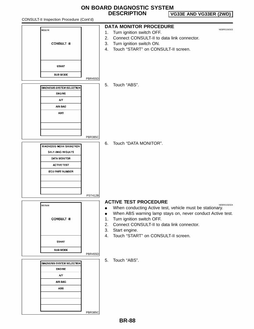
PBR455D
DATA MONITOR PROCEDURENEBR0156S03
1. Turn ignition switch OFF.2. Connect CONSULT-II to data link connector.3. Turn ignition switch ON.4. Touch “START” on CONSULT-II screen.
PBR385C
5. Touch “ABS”.
PST412B
6. Touch “DATA MONITOR”.
PBR455D
ACTIVE TEST PROCEDURENEBR0156S04
When conducting Active test, vehicle must be stationary. When ABS warning lamp stays on, never conduct Active test.1. Turn ignition switch OFF.2. Connect CONSULT-II to data link connector.3. Start engine.4. Touch “START” on CONSULT-II screen.
PBR385C
5. Touch “ABS”.
ON BOARD DIAGNOSTIC SYSTEMDESCRIPTION VG33E AND VG33ER (2WD)
CONSULT-II Inspection Procedure (Cont’d)
BR-88
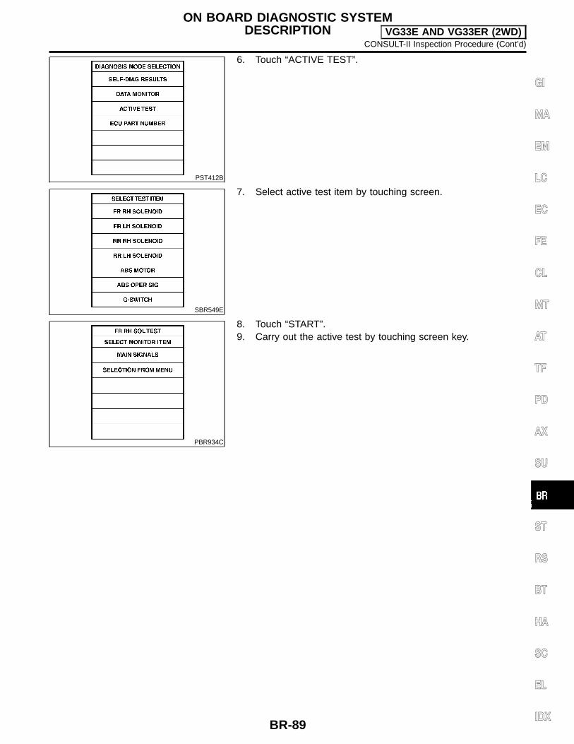
PST412B
6. Touch “ACTIVE TEST”.
SBR549E
7. Select active test item by touching screen.
PBR934C
8. Touch “START”.9. Carry out the active test by touching screen key.
ON BOARD DIAGNOSTIC SYSTEMDESCRIPTION VG33E AND VG33ER (2WD)
CONSULT-II Inspection Procedure (Cont’d)
BR-89
GI
MA
EM
LC
EC
FE
CL
MT
AT
TF
PD
AX
SU
ST
RS
BT
HA
SC
EL
IDX
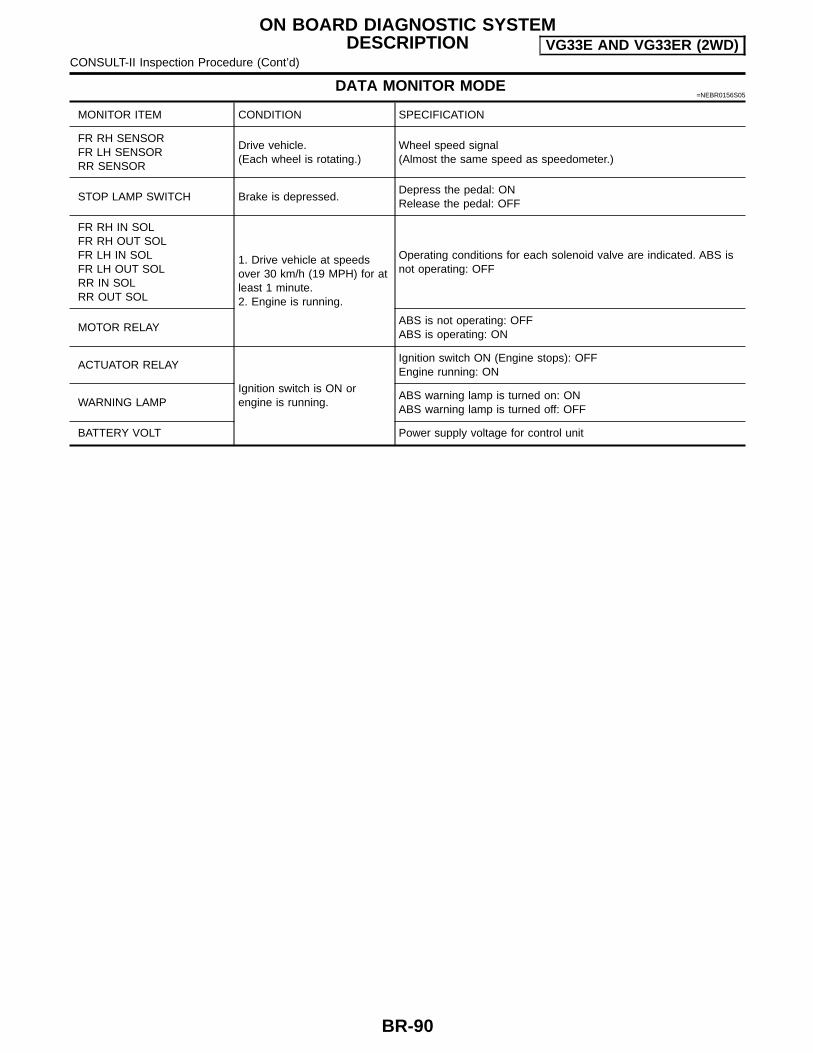
DATA MONITOR MODE=NEBR0156S05
MONITOR ITEM CONDITION SPECIFICATION
FR RH SENSORFR LH SENSORRR SENSOR
Drive vehicle.(Each wheel is rotating.)
Wheel speed signal(Almost the same speed as speedometer.)
STOP LAMP SWITCH Brake is depressed.Depress the pedal: ONRelease the pedal: OFF
FR RH IN SOLFR RH OUT SOLFR LH IN SOLFR LH OUT SOLRR IN SOLRR OUT SOL
1. Drive vehicle at speedsover 30 km/h (19 MPH) for atleast 1 minute.2. Engine is running.
Operating conditions for each solenoid valve are indicated. ABS isnot operating: OFF
MOTOR RELAYABS is not operating: OFFABS is operating: ON
ACTUATOR RELAY
Ignition switch is ON orengine is running.
Ignition switch ON (Engine stops): OFFEngine running: ON
WARNING LAMPABS warning lamp is turned on: ONABS warning lamp is turned off: OFF
BATTERY VOLT Power supply voltage for control unit
ON BOARD DIAGNOSTIC SYSTEMDESCRIPTION VG33E AND VG33ER (2WD)
CONSULT-II Inspection Procedure (Cont’d)
BR-90

ACTIVE TEST MODE=NEBR0156S06
TEST ITEM CONDITION JUDGEMENT
FR RH SOLENOIDFR LH SOLENOIDRR SOLENOID
Brake fluid pressure control operation
Engine is running.
IN SOL OUT SOL
UP (Increase): OFF OFF
KEEP (Hold): ON OFF
DOWN (Decrease): ON ON
ABS MOTORABS actuator motorON: Motor runs (ABS motor relay ON)OFF: Motor stops (ABS motor relay OFF)
NOTE:Active test will automatically stop ten seconds after the test starts. (TEST IS STOPPED monitor shows ON.)
LBR144
Ground Circuit CheckNEBR0179
ABS ACTUATOR AND ELECTRIC UNIT GROUNDNEBR0179S01
Check resistance between ABS actuator and electric unit con-nector terminals (16, 19) and ground.
Resistance: approximately 0Ω
ON BOARD DIAGNOSTIC SYSTEMDESCRIPTION VG33E AND VG33ER (2WD)
CONSULT-II Inspection Procedure (Cont’d)
BR-91
GI
MA
EM
LC
EC
FE
CL
MT
AT
TF
PD
AX
SU
ST
RS
BT
HA
SC
EL
IDX

NEBR0191
Malfunction Code/Symptom ChartNEBR0191S01
Code No. (No. of warning lamp flashes) Malfunctioning part Reference Page
45 Actuator front left outlet solenoid valve BR-95
46 Actuator front left inlet solenoid valve BR-95
41 Actuator front right outlet solenoid valve BR-95
42 Actuator front right inlet solenoid valve BR-95
55 Actuator rear outlet solenoid valve BR-95
56 Actuator rear inlet solenoid valve BR-95
25 1 Front left sensor (open-circuit) BR-93
26 1 Front left sensor (short-circuit) BR-93
21 1 Front right sensor (open-circuit) BR-93
22 1 Front right sensor (short-circuit) BR-93
35 1 Rear sensor (open-circuit) BR-93
36 1 Rear sensor (short-circuit) BR-93
18 1 Sensor rotor BR-93
61 3 Actuator motor or motor relay BR-97
63 Solenoid valve relay BR-95
57 2 Power supply (Low voltage) BR-99
71 Control unit BR-101
Warning lamp stays on when ignitionswitch is turned ON.
Control unit power supply circuitWarning lamp bulb circuitControl unit or control unit connectorSolenoid valve relay stuckPower supply for solenoid valve relay coil
BR-107
Warning lamp does not come onWhen ignition switch is turned ON.
Fuse, warning lamp bulb or warning lamp circuitControl unit
BR-105
Pedal vibration and noise — BR-105
Long stopping distance — BR-104
Unexpected pedal action — BR-103
ABS does not work — BR-104
ABS works frequently — BR-102
1: If one or more wheels spin on a rough or slippery road for 40 seconds or more, the ABS warning lamp will illuminate. This doesnot indicate a malfunction. Only in the case of the short-circuit (Code Nos. 26, 22, 32 and 36), after repair the ABS warning lamp alsoilluminates when the ignition switch is turned ON. In this case, drive the vehicle at speeds greater than 30 km/h (19 MPH) for approxi-mately 1 minute as specified in “SELF-DIAGNOSIS PROCEDURE”, BR-83. Check to ensure that the ABS warning lamp goes out whilethe vehicle is being driven. 2: The trouble code “57”, which refers to a low power supply voltage, does not indicate that the ABS control unit is malfunctioning. Donot replace the ABS control unit with a new one. 3: The trouble code “61” can sometimes appear when the ABS motor is not properly grounded. If it appears, be sure to check thecondition of the ABS motor ground circuit connection.
TROUBLE DIAGNOSIS — GENERALDESCRIPTION VG33E AND VG33ER (2WD)
Malfunction Code/Symptom Chart
BR-92

Wheel Sensor or RotorNEBR0184
MALFUNCTION CODE NO. 21, 22, 25, 26, 35, 36 OR 18NEBR0184S01
NOTE:Wheel position should be distinguished by code No. except codeNo. 18 (sensor rotor).
1 INSPECTION START
Wheel sensor inspection
WBR178
GO TO 2.
2 CHECK CONNECTOR
1. Disconnect connectors from ABS actuator and electric unit and wheel sensor of malfunction code No. Check terminalsfor damage or loose connection. Then reconnect connectors.
2. Carry out “Self-diagnosis” again. Refer to BR-83.
Does warning lamp activate again?
Yes GO TO 3.
No INSPECTION END
3 CHECK WHEEL SENSOR ELECTRICAL
1. Disconnect ABS actuator and electric unit connector.2. Check resistance between ABS actuator and electric unit connector E39 terminals.
Code No. 21 or 22 (Front RH wheel)Terminals 3 and 5Code No. 25 or 26 (Front LH wheel)Terminals 6 and 7Code No. 35 or 36 (Rear wheel)Terminals 1 and 2
LBR136
Resistance:Front 1.28 - 1.92 kΩRear 1.05 - 1.35 kΩ
Are front and rear resistance values within specifications?
Yes GO TO 5.
No GO TO 4.
TROUBLE DIAGNOSES FORSELF-DIAGNOSTIC ITEMS VG33E AND VG33ER (2WD)
Wheel Sensor or Rotor
BR-93
GI
MA
EM
LC
EC
FE
CL
MT
AT
TF
PD
AX
SU
ST
RS
BT
HA
SC
EL
IDX

4 CHECK WHEEL SENSOR
Check each sensor for resistance.
WBR179
Resistance:Front 1.28 - 1.92 kΩRear 1.05 - 1.35 kΩ
Are front and rear sensor resistance values within specifications?
Yes Check the following.If NG, repair harness or connectors. Harness connectors E2, E16, E39, C6 Harness for open or short between wheel sensor connectors and ABS actuator and
electric unit
No Replace wheel sensor.
5 CHECK TIRE
Check for inflation pressure, wear and size of each tire. (See NOTE)
Are tire pressure and size correct and is tire wear within specifications?
Yes GO TO 6.
No Adjust tire pressure or replace tire(s). (See NOTE)
6 CHECK WHEEL BEARING
Check wheel bearing axial end play. (See NOTE)
Is wheel bearing axial end play within specifications? Refer to AX-5, “FRONT WHEEL BEARING” and AX-28, “REARWHEEL BEARING”.
Yes GO TO 7.
No Check wheel bearing. Refer to AX-5, “FRONT WHEEL BEARING” and AX-28, “REARWHEEL BEARING”.
7 CHECK SENSOR ROTOR
Check sensor rotor for teeth damage. (See NOTE)
Is sensor rotor free from damage?
Yes Check ABS actuator and electric unit pin terminals for damage or the connection of ABSactuator and electric unit harness connector. Reconnect ABS actuator and electric unitharness connector. Then retest.
No Replace sensor rotor. (See NOTE)
TROUBLE DIAGNOSES FORSELF-DIAGNOSTIC ITEMS VG33E AND VG33ER (2WD)
Wheel Sensor or Rotor (Cont’d)
BR-94
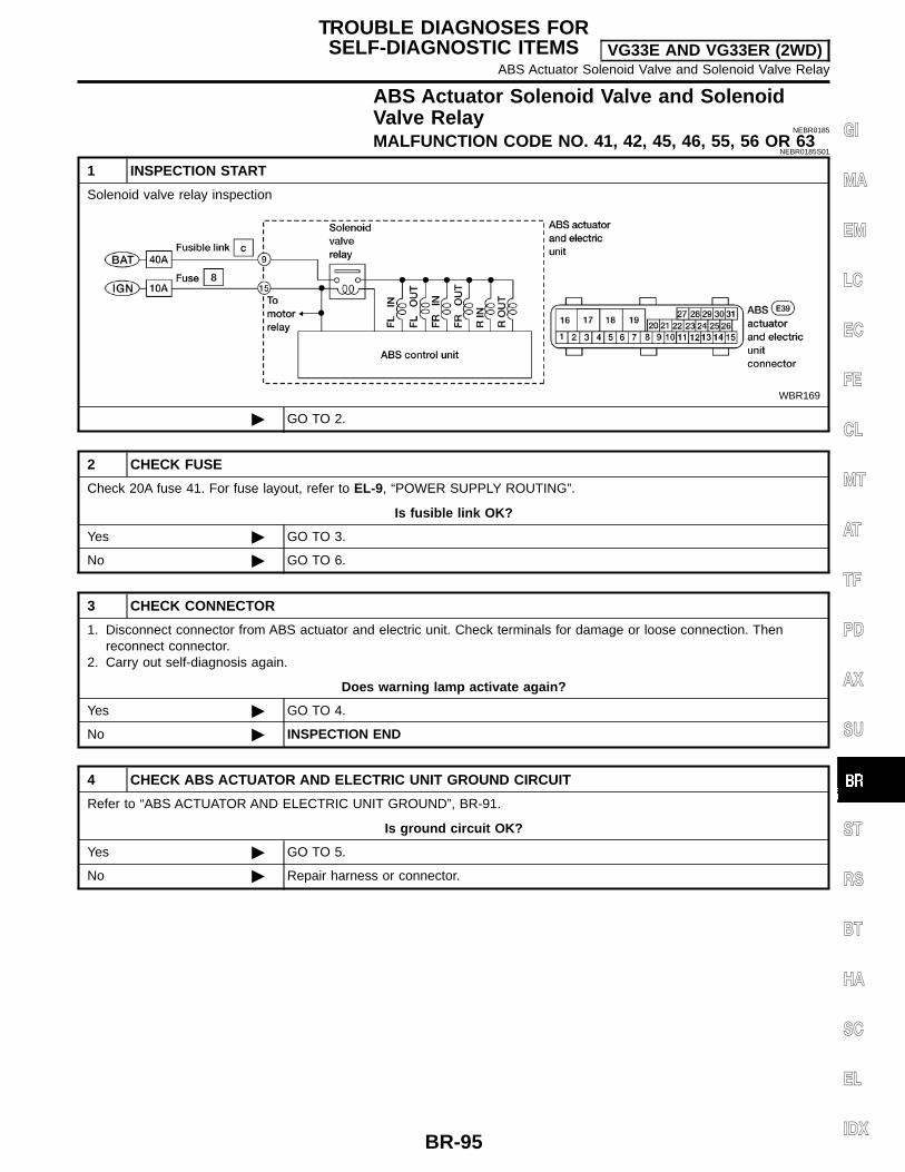
ABS Actuator Solenoid Valve and SolenoidValve Relay
NEBR0185
MALFUNCTION CODE NO. 41, 42, 45, 46, 55, 56 OR 63NEBR0185S01
1 INSPECTION START
Solenoid valve relay inspection
WBR169
GO TO 2.
2 CHECK FUSE
Check 20A fuse 41. For fuse layout, refer to EL-9, “POWER SUPPLY ROUTING”.
Is fusible link OK?
Yes GO TO 3.
No GO TO 6.
3 CHECK CONNECTOR
1. Disconnect connector from ABS actuator and electric unit. Check terminals for damage or loose connection. Thenreconnect connector.
2. Carry out self-diagnosis again.
Does warning lamp activate again?
Yes GO TO 4.
No INSPECTION END
4 CHECK ABS ACTUATOR AND ELECTRIC UNIT GROUND CIRCUIT
Refer to “ABS ACTUATOR AND ELECTRIC UNIT GROUND”, BR-91.
Is ground circuit OK?
Yes GO TO 5.
No Repair harness or connector.
TROUBLE DIAGNOSES FORSELF-DIAGNOSTIC ITEMS VG33E AND VG33ER (2WD)
ABS Actuator Solenoid Valve and Solenoid Valve Relay
BR-95
GI
MA
EM
LC
EC
FE
CL
MT
AT
TF
PD
AX
SU
ST
RS
BT
HA
SC
EL
IDX

5 CHECK SOLENOID VALVE POWER SUPPLY CIRCUIT
1. Disconnect ABS actuator and electric unit connector.2. Check voltage between ABS actuator and electric unit connector E39 (body side) terminal 18 and ground.
ABR646
Does battery voltage exist?
Yes Replace ABS actuator and electric unit.
No Check the following.If NG, repair harness or connectors. Harness connector E39 Harness for open or short between ABS actuator and electric unit and fuse
6 REPLACE FUSE
Replace fuse.
Does the fuse blow out when ignition switch is turned ON?
Yes GO TO 7.
No INSPECTION END
7 CHECK SOLENOID VALVE RELAY POWER SUPPLY CIRCUIT FOR SHORT
1. Disconnect battery cable and ABS actuator and electric unit connector.2. Check continuity between ABS actuator and electric unit connector E39 (body side) terminal 18 and ground.
ABR647
Continuity should not exist.
Does continuity exist?
Yes Check the following.If NG, repair harness or connector. Harness connector E39 Harness for open or short between ABS actuator and electric unit and fuse
No Replace ABS actuator and electric unit.
TROUBLE DIAGNOSES FORSELF-DIAGNOSTIC ITEMS VG33E AND VG33ER (2WD)
ABS Actuator Solenoid Valve and Solenoid Valve Relay (Cont’d)
BR-96
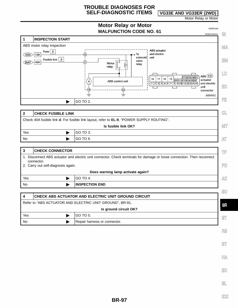
Motor Relay or MotorNEBR0186
MALFUNCTION CODE NO. 61NEBR0186S01
1 INSPECTION START
ABS motor relay inspection
ABR842
GO TO 2.
2 CHECK FUSIBLE LINK
Check 40A fusible link d. For fusible link layout, refer to EL-9, “POWER SUPPLY ROUTING”.
Is fusible link OK?
Yes GO TO 3.
No GO TO 6.
3 CHECK CONNECTOR
1. Disconnect ABS actuator and electric unit connector. Check terminals for damage or loose connection. Then reconnectconnector.
2. Carry out self-diagnosis again.
Does warning lamp activate again?
Yes GO TO 4.
No INSPECTION END
4 CHECK ABS ACTUATOR AND ELECTRIC UNIT GROUND CIRCUIT
Refer to “ABS ACTUATOR AND ELECTRIC UNIT GROUND”, BR-91.
Is ground circuit OK?
Yes GO TO 5.
No Repair harness or connector.
TROUBLE DIAGNOSES FORSELF-DIAGNOSTIC ITEMS VG33E AND VG33ER (2WD)
Motor Relay or Motor
BR-97
GI
MA
EM
LC
EC
FE
CL
MT
AT
TF
PD
AX
SU
ST
RS
BT
HA
SC
EL
IDX

5 CHECK MOTOR RELAY POWER SUPPLY CIRCUIT
1. Disconnect ABS actuator and electric unit connector.2. Check voltage between ABS actuator and electric unit connector E39 terminal 17 and ground.
ABR649
Does battery voltage exist?
Yes Replace ABS actuator and electric unit.
No Check the following.If NG, repair harness or connector. Harness connector E39 Harness for open or short between ABS actuator and electric unit and fusible link
6 REPLACE FUSIBLE LINK
Replace fusible link.
Does the fusible link blow out when ignition switch is turned ON?
Yes GO TO 7.
No INSPECTION END
7 CHECK ABS ACTUATOR MOTOR POWER SUPPLY CIRCUIT FOR SHORT
1. Disconnect battery cable and ABS actuator and electric unit connector.2. Check continuity between ABS actuator and electric unit connector E39 terminal 17 and ground.
ABR650
Continuity should not exist.
Does continuity exist?
Yes Check the following.If NG, repair harness or connector. Harness connector E39 Harness for open or short between ABS actuator and electric unit and fusible link
No Replace ABS actuator and electric unit.
TROUBLE DIAGNOSES FORSELF-DIAGNOSTIC ITEMS VG33E AND VG33ER (2WD)
Motor Relay or Motor (Cont’d)
BR-98
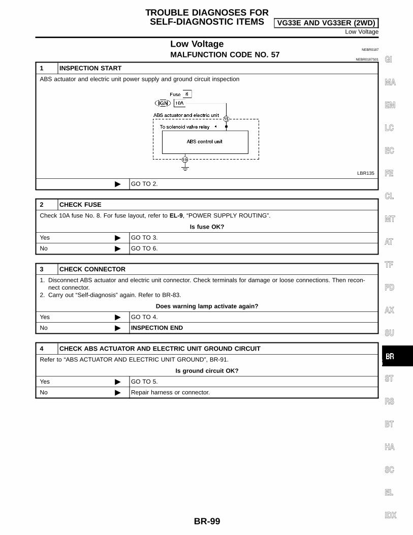
Low VoltageNEBR0187
MALFUNCTION CODE NO. 57NEBR0187S01
1 INSPECTION START
ABS actuator and electric unit power supply and ground circuit inspection
LBR135
GO TO 2.
2 CHECK FUSE
Check 10A fuse No. 8. For fuse layout, refer to EL-9, “POWER SUPPLY ROUTING”.
Is fuse OK?
Yes GO TO 3.
No GO TO 6.
3 CHECK CONNECTOR
1. Disconnect ABS actuator and electric unit connector. Check terminals for damage or loose connections. Then recon-nect connector.
2. Carry out “Self-diagnosis” again. Refer to BR-83.
Does warning lamp activate again?
Yes GO TO 4.
No INSPECTION END
4 CHECK ABS ACTUATOR AND ELECTRIC UNIT GROUND CIRCUIT
Refer to “ABS ACTUATOR AND ELECTRIC UNIT GROUND”, BR-91.
Is ground circuit OK?
Yes GO TO 5.
No Repair harness or connector.
TROUBLE DIAGNOSES FORSELF-DIAGNOSTIC ITEMS VG33E AND VG33ER (2WD)
Low Voltage
BR-99
GI
MA
EM
LC
EC
FE
CL
MT
AT
TF
PD
AX
SU
ST
RS
BT
HA
SC
EL
IDX

5 CHECK ABS ACTUATOR AND ELECTRIC UNIT POWER SUPPLY CIRCUIT
1. Disconnect ABS actuator and electric unit connector.2. Check voltage between ABS actuator and electric unit connector E39 terminal 15 and ground.
ABR652
Does battery voltage exist when ignition switch is turned ON?
Yes Replace ABS actuator and electric unit.
No Check the following.If NG, repair harness or connector. Harness connector E39 Harness for open or short between ABS actuator and electric unit and fuse
6 REPLACE FUSE
Replace fuse.
Does the fuse blow out when ignition switch is turned ON?
Yes GO TO 7.
No INSPECTION END
7 CHECK ABS ACTUATOR AND ELECTRIC UNIT POWER SUPPLY CIRCUIT FOR SHORT
1. Disconnect battery cable and ABS actuator and electric unit connector.2. Check continuity between ABS actuator and electric unit connector E39 terminal 15 and ground.
ABR775
Continuity should not exist.
Does continuity exist?
Yes Check the following.If NG, repair harness or connector. Harness connector E39 Harness for open or short between ABS actuator and electric unit and fuse
No Replace ABS actuator and electric unit.
TROUBLE DIAGNOSES FORSELF-DIAGNOSTIC ITEMS VG33E AND VG33ER (2WD)
Low Voltage (Cont’d)
BR-100
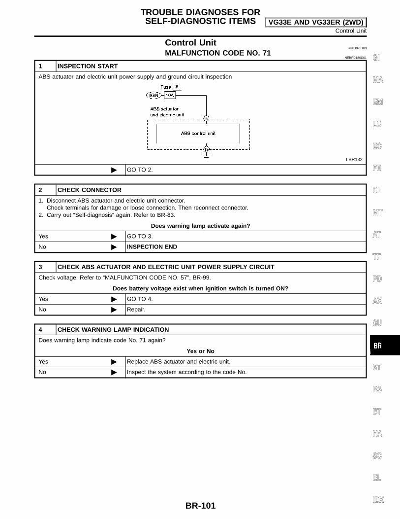
Control Unit=NEBR0189
MALFUNCTION CODE NO. 71NEBR0189S01
1 INSPECTION START
ABS actuator and electric unit power supply and ground circuit inspection
LBR132
GO TO 2.
2 CHECK CONNECTOR
1. Disconnect ABS actuator and electric unit connector.Check terminals for damage or loose connection. Then reconnect connector.
2. Carry out “Self-diagnosis” again. Refer to BR-83.
Does warning lamp activate again?
Yes GO TO 3.
No INSPECTION END
3 CHECK ABS ACTUATOR AND ELECTRIC UNIT POWER SUPPLY CIRCUIT
Check voltage. Refer to “MALFUNCTION CODE NO. 57”, BR-99.
Does battery voltage exist when ignition switch is turned ON?
Yes GO TO 4.
No Repair.
4 CHECK WARNING LAMP INDICATION
Does warning lamp indicate code No. 71 again?
Yes or No
Yes Replace ABS actuator and electric unit.
No Inspect the system according to the code No.
TROUBLE DIAGNOSES FORSELF-DIAGNOSTIC ITEMS VG33E AND VG33ER (2WD)
Control Unit
BR-101
GI
MA
EM
LC
EC
FE
CL
MT
AT
TF
PD
AX
SU
ST
RS
BT
HA
SC
EL
IDX

1. ABS Works FrequentlyNEBR0192
1 CHECK BRAKE FLUID PRESSURE
Check brake fluid pressure distribution.Refer to “PROPORTIONING VALVE (VG33E and VG33ER)”, BR-14.
Is brake fluid pressure distribution normal?
Yes GO TO 2.
No Repair. Then perform “Preliminary Check”.Refer to BR-75.
2 CHECK WHEEL SENSOR
1. Check wheel sensor connector for terminal damage or loose connections.2. Perform wheel sensor mechanical check.
Refer to “Wheel Sensor or Rotor”, BR-93.
Is wheel sensor mechanism OK?
Yes GO TO 3.
No Repair.
3 CHECK FRONT AXLE
Check front axles for excessive looseness. Refer to AX-5, “Front Wheel Bearing”.
Is front axle installed properly?
Yes Go to Test No. 3, “2. Unexpected Pedal Action”, BR-103.
No Repair.
TROUBLE DIAGNOSES FORSYMPTOMS VG33E AND VG33ER (2WD)
1. ABS Works Frequently
BR-102

2. Unexpected Pedal Action=NEBR0193
1 CHECK BRAKE PEDAL STROKE
Check brake pedal stroke.
SBR540A
Is brake pedal stroke excessively large?
Yes Perform “Preliminary Check”, refer to BR-75.
No GO TO 2.
2 CHECK MECHANICAL BRAKE SYSTEM PERFORMANCE
Disconnect ABS actuator and electric unit connector and check whether brake is effective.
Does brake system function properly when brake pedal is depressed?
Yes GO TO 3.
No Perform “Preliminary Check”, refer to BR-75.
3 CHECK WARNING LAMP INDICATION
Ensure warning lamp remains off while driving.
ABR837
Is warning lamp turned off?
Yes GO TO 4.
No Perform “Self-diagnosis”, refer to BR-83.
4 CHECK WHEEL SENSOR
1. Check wheel sensor connector for terminal damage or loose connection.2. Perform wheel sensor mechanical check. Refer to Test No. 7, “Wheel Sensor or Rotor”, BR-93.
Is wheel sensor mechanism OK?
Yes Check ABS actuator and electric unit pin terminals for damage or the connection of ABSactuator and electric unit harness connector.Reconnect ABS actuator and electric unit harness connector.Then retest.
No Repair.
TROUBLE DIAGNOSES FORSYMPTOMS VG33E AND VG33ER (2WD)
2. Unexpected Pedal Action
BR-103
GI
MA
EM
LC
EC
FE
CL
MT
AT
TF
PD
AX
SU
ST
RS
BT
HA
SC
EL
IDX
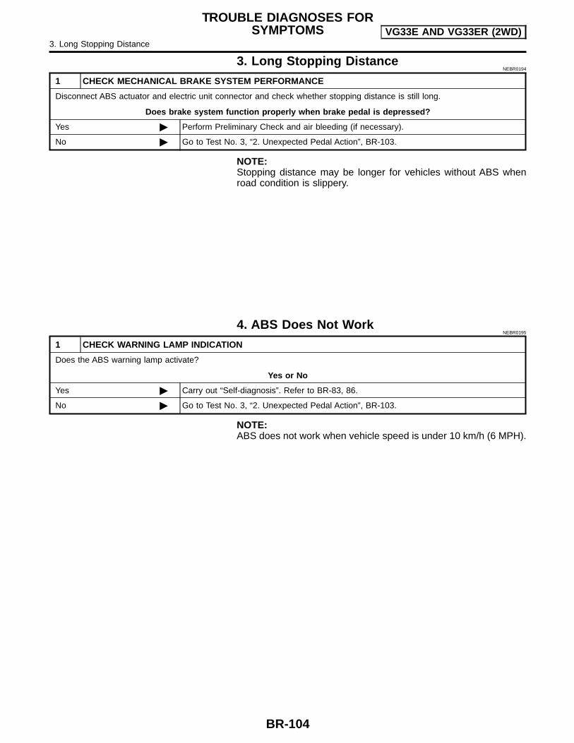
3. Long Stopping DistanceNEBR0194
1 CHECK MECHANICAL BRAKE SYSTEM PERFORMANCE
Disconnect ABS actuator and electric unit connector and check whether stopping distance is still long.
Does brake system function properly when brake pedal is depressed?
Yes Perform Preliminary Check and air bleeding (if necessary).
No Go to Test No. 3, “2. Unexpected Pedal Action”, BR-103.
NOTE:Stopping distance may be longer for vehicles without ABS whenroad condition is slippery.
4. ABS Does Not WorkNEBR0195
1 CHECK WARNING LAMP INDICATION
Does the ABS warning lamp activate?
Yes or No
Yes Carry out “Self-diagnosis”. Refer to BR-83, 86.
No Go to Test No. 3, “2. Unexpected Pedal Action”, BR-103.
NOTE:ABS does not work when vehicle speed is under 10 km/h (6 MPH).
TROUBLE DIAGNOSES FORSYMPTOMS VG33E AND VG33ER (2WD)
3. Long Stopping Distance
BR-104

5. Pedal Vibration and Noise=NEBR0196
1 INSPECTION START
Pedal vibration and noise inspection
SAT797A
GO TO 2.
2 CHECK SYMPTOM
1. Apply brake.2. Start engine.
Does the symptom appear only when engine is started?
Yes Carry out “Self-diagnosis”. Refer to BR-83.
No Go to Test No. 3, “2. Unexpected Pedal Action”, BR-103.
NOTE:ABS may operate and cause vibration under any of the followingconditions. Applying brake gradually when shifting or operating clutch. Low friction (slippery) road. High speed cornering. Driving over bumps and potholes. Engine speed is over 5,000 rpm with vehicle stopped.
6. Warning Lamp Does Not Come On WhenIgnition Switch Is Turned ON
NEBR0197
1 INSPECTION START
Warning lamp circuit inspection
WBR371
GO TO 2.
TROUBLE DIAGNOSES FORSYMPTOMS VG33E AND VG33ER (2WD)
5. Pedal Vibration and Noise
BR-105
GI
MA
EM
LC
EC
FE
CL
MT
AT
TF
PD
AX
SU
ST
RS
BT
HA
SC
EL
IDX

2 CHECK FUSE
Check 10A fuse No. 11. For fuse layout, refer to EL-9, “POWER SUPPLY ROUTING”.
Is fuse OK?
Yes GO TO 3.
No Replace fuse.
3 CHECK WARNING LAMP ACTIVATE
Disconnect ABS actuator and electric unit connector.
ABR838
Does the warning lamp activate?
Yes Replace ABS actuator and electric unit.
No GO TO 4.
4 CHECK HARNESS FOR SHORT
1. Disconnect ABS actuator and electric unit connector E39 and combination meter connector M38.2. Check continuity between ABS actuator and electric unit connector E39 terminal 17 and ground.
LBR130
Continuity should not exist.
Does continuity exist?
Yes Repair harness or connectors.
No Check combination meter.Refer to EL-84, “WARNING LAMPS”.
TROUBLE DIAGNOSES FORSYMPTOMS VG33E AND VG33ER (2WD)
6. Warning Lamp Does Not Come On When Ignition Switch Is Turned ON (Cont’d)
BR-106

7. Warning Lamp Stays On When IgnitionSwitch Is Turned On
=NEBR0198
1 INSPECTION START
ABS control unit inspection
WBR372
GO TO 2.
2 CHECK FUSE
Check 10A fuse No. 8. For fuse layout, refer to EL-9, “POWER SUPPLY ROUTING”.
Is fuse OK?
Yes GO TO 3.
No GO TO 8.
3 CHECK HARNESS CONNECTOR
Check ABS actuator and electric unit pin terminals for damage or bad connection of ABS actuator and electric unit harnessconnector. Reconnect ABS actuator and electric unit harness connector. Then retest.
Does warning lamp stay on when ignition switch is turned ON?
Yes GO TO 4.
No INSPECTION END
4 CHECK ABS ACTUATOR AND ELECTRIC UNIT GROUND CIRCUIT
Refer to “Ground Circuit Check”, BR-91.
Is ground circuit OK?
Yes GO TO 5.
No Repair harness or connector.
TROUBLE DIAGNOSES FORSYMPTOMS VG33E AND VG33ER (2WD)
7. Warning Lamp Stays On When Ignition Switch Is Turned On
BR-107
GI
MA
EM
LC
EC
FE
CL
MT
AT
TF
PD
AX
SU
ST
RS
BT
HA
SC
EL
IDX

5 CHECK ABS ACTUATOR AND ELECTRIC UNIT POWER SUPPLY CIRCUIT
1. Disconnect ABS actuator and electric unit connector.2. Check voltage between ABS actuator and electric unit connector E39 terminal 15 and ground.
ABR652
Does battery voltage exist when ignition switch is turned ON?
Yes GO TO 6.
No Check the following.If NG, repair harness or connector. Harness connector E39 Harness for open or short between ABS actuator and electric unit and fuse No. 8
6 CHECK WARNING LAMP
1. Disconnect ABS actuator and electric unit connector.Connect suitable wire between ABS actuator and electric unit connector E39 terminal 10 and ground.
LBR133
Does the warning lamp deactivate?
Yes Replace ABS actuator and electric unit.
No GO TO 7.
TROUBLE DIAGNOSES FORSYMPTOMS VG33E AND VG33ER (2WD)
7. Warning Lamp Stays On When Ignition Switch Is Turned On (Cont’d)
BR-108
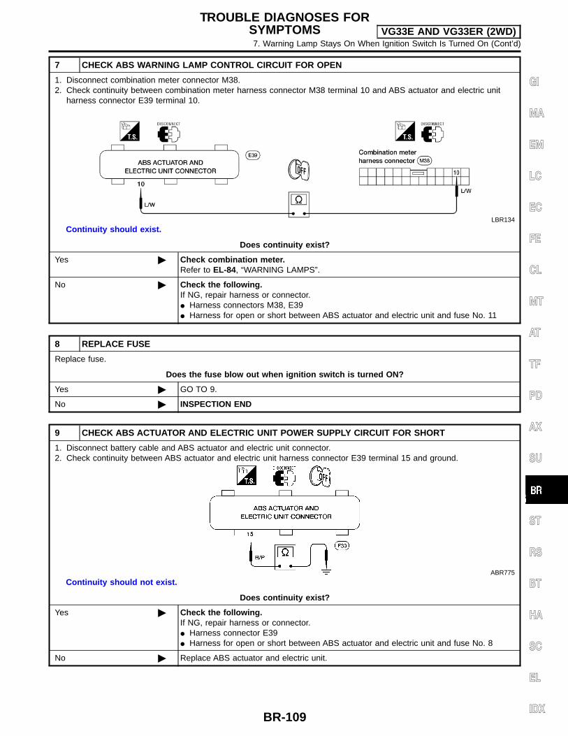
7 CHECK ABS WARNING LAMP CONTROL CIRCUIT FOR OPEN
1. Disconnect combination meter connector M38.2. Check continuity between combination meter harness connector M38 terminal 10 and ABS actuator and electric unit
harness connector E39 terminal 10.
LBR134
Continuity should exist.
Does continuity exist?
Yes Check combination meter.Refer to EL-84, “WARNING LAMPS”.
No Check the following.If NG, repair harness or connector. Harness connectors M38, E39 Harness for open or short between ABS actuator and electric unit and fuse No. 11
8 REPLACE FUSE
Replace fuse.
Does the fuse blow out when ignition switch is turned ON?
Yes GO TO 9.
No INSPECTION END
9 CHECK ABS ACTUATOR AND ELECTRIC UNIT POWER SUPPLY CIRCUIT FOR SHORT
1. Disconnect battery cable and ABS actuator and electric unit connector.2. Check continuity between ABS actuator and electric unit harness connector E39 terminal 15 and ground.
ABR775
Continuity should not exist.
Does continuity exist?
Yes Check the following.If NG, repair harness or connector. Harness connector E39 Harness for open or short between ABS actuator and electric unit and fuse No. 8
No Replace ABS actuator and electric unit.
TROUBLE DIAGNOSES FORSYMPTOMS VG33E AND VG33ER (2WD)7. Warning Lamp Stays On When Ignition Switch Is Turned On (Cont’d)
BR-109
GI
MA
EM
LC
EC
FE
CL
MT
AT
TF
PD
AX
SU
ST
RS
BT
HA
SC
EL
IDX

PurposeNEBR0280
The anti-lock brake system (ABS) consists of electronic and hydraulic components. It allows for control ofbraking force so locking of the wheels can be avoided.1) Improves proper tracking performance through steering wheel operation.2) Eases obstacle avoidance through steering wheel operation.3) Improves vehicle stability.
OperationNEBR0281
When the vehicle speed is less than 10 km/h (6 MPH) this system does not work. The anti-lock brake system (ABS) has a self-test function. The system turns on the ABS warning lamp for
1 second each time the ignition switch is turned ON. After the engine is started, the ABS warning lampturns off. The system performs a test the first time the vehicle reaches 6 km/h (4 MPH). A mechanical noisemay be heard as the ABS performs this self-test. This is a normal part of the self-test feature. If a mal-function is found during this check, the ABS warning lamp will stay on.
While driving, a mechanical noise may be heard during ABS operation. This is a normal condition.
ABS Hydraulic CircuitNEBR0282
SBR859D
1. Inlet solenoid valve2. Outlet solenoid valve3. Pump
4. Motor5. Bypass check valve6. Damper
7. Solenoid valve relay actuator8. Bypass check valve9. Damper
DESCRIPTION VG33E AND VG33ER (4WD)Purpose
BR-110

System ComponentsNEBR0283
ABR809
LBR333
System DescriptionNEBR0284
WHEEL SENSORNEBR0284S01
The sensor units consist of a gear-shaped sensor rotor and a sen-sor element. The front sensors are installed on the back of the frontbrake rotors. A rear sensor is installed at each rear brake drum. Asthe wheel rotates, the sensor generates a square-wave pattern.The frequency increases as the rotating speed increases.
ABR910
CONTROL UNIT (BUILT-IN ABS ACTUATOR ANDELECTRIC UNIT)
NEBR0284S02
The control unit computes the wheel rotating speed by the signalcurrent sent from the sensor. Then it supplies a DC current to theactuator solenoid valve. It also controls ON-OFF operation of thevalve relay and motor relay. If any electrical malfunction should bedetected in the system, the control unit causes the warning lampto light up. In this condition, the ABS will be deactivated by thecontrol unit, and the vehicle brake system reverts to normal opera-tion. For control unit layout, refer to “ABS ACTUATOR AND ELEC-TRIC UNIT”, BR-112.
DESCRIPTION VG33E AND VG33ER (4WD)System Components
BR-111
GI
MA
EM
LC
EC
FE
CL
MT
AT
TF
PD
AX
SU
ST
RS
BT
HA
SC
EL
IDX
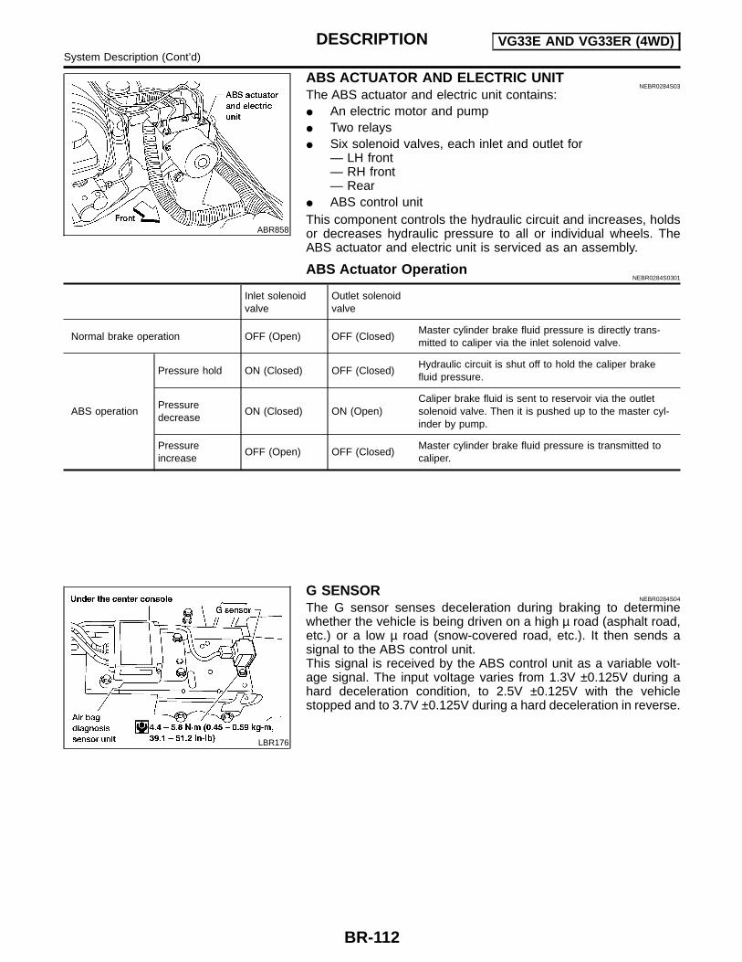
ABR858
ABS ACTUATOR AND ELECTRIC UNITNEBR0284S03
The ABS actuator and electric unit contains: An electric motor and pump Two relays Six solenoid valves, each inlet and outlet for
— LH front— RH front— Rear
ABS control unitThis component controls the hydraulic circuit and increases, holdsor decreases hydraulic pressure to all or individual wheels. TheABS actuator and electric unit is serviced as an assembly.
ABS Actuator OperationNEBR0284S0301
Inlet solenoidvalve
Outlet solenoidvalve
Normal brake operation OFF (Open) OFF (Closed)Master cylinder brake fluid pressure is directly trans-mitted to caliper via the inlet solenoid valve.
ABS operation
Pressure hold ON (Closed) OFF (Closed)Hydraulic circuit is shut off to hold the caliper brakefluid pressure.
Pressuredecrease
ON (Closed) ON (Open)Caliper brake fluid is sent to reservoir via the outletsolenoid valve. Then it is pushed up to the master cyl-inder by pump.
Pressureincrease
OFF (Open) OFF (Closed)Master cylinder brake fluid pressure is transmitted tocaliper.
LBR176
G SENSORNEBR0284S04
The G sensor senses deceleration during braking to determinewhether the vehicle is being driven on a high µ road (asphalt road,etc.) or a low µ road (snow-covered road, etc.). It then sends asignal to the ABS control unit.This signal is received by the ABS control unit as a variable volt-age signal. The input voltage varies from 1.3V ±0.125V during ahard deceleration condition, to 2.5V ±0.125V with the vehiclestopped and to 3.7V ±0.125V during a hard deceleration in reverse.
DESCRIPTION VG33E AND VG33ER (4WD)System Description (Cont’d)
BR-112

SEF233G
SEF234G
How to Perform Trouble Diagnoses for Quickand Accurate Repair
NEBR0285
INTRODUCTIONNEBR0285S01
The ABS system has an electronic control unit to control majorfunctions. The control unit accepts input signals from sensors andinstantly drives the actuators. It is essential that both kinds of sig-nals are proper and stable. It is also important to check for conven-tional problems: such as air leaks in booster lines, lack of brakefluid, or other problems with the brake system.It is much more difficult to diagnose a problem that occurs intermit-tently rather than continuously. Most intermittent problems arecaused by poor electric connections or faulty wiring. In this case,careful checking of suspicious circuits may help prevent thereplacement of good parts.A visual check only may not find the cause of the problems, so aroad test should be performed.Before undertaking actual checks, take a few minutes to talk witha customer who approaches with an ABS complaint. The customeris a very good source of information on such problems; especiallyintermittent ones. By talking to the customer, find out what symp-toms are present and under what conditions they occur. Start yourdiagnosis by looking for “conventional” problems first. This is oneof the best ways to troubleshoot brake problems on an ABS con-trolled vehicle.Also check related Service bulletins for information.
TROUBLE DIAGNOSIS —INTRODUCTION VG33E AND VG33ER (4WD)
How to Perform Trouble Diagnoses for Quick and Accurate Repair
BR-113
GI
MA
EM
LC
EC
FE
CL
MT
AT
TF
PD
AX
SU
ST
RS
BT
HA
SC
EL
IDX

Preliminary CheckNEBR0286
1 CHECK BRAKE FLUID
Check brake fluid for contamination.
Has brake fluid been contaminated?
Yes Replace. GO TO 2.
No GO TO 2.
2 CHECK BRAKE FLUID LEVEL
Check brake fluid level in reservoir tank.Low fluid level may indicate brake pad wear or leakage from brake line.
SBR451D
Is brake fluid filled between MAX and MIN lines on reservoir tank ?
Yes GO TO 3.
No Fill up brake fluid. GO TO 3.
3 CHECK BRAKE LINE
Check brake line for leakage.
SBR389C
Is leakage present at or around brake lines, tubes or hoses or are any of these parts cracked or damaged?
Yes Repair. GO TO 4.
No GO TO 4.
TROUBLE DIAGNOSIS —BASIC INSPECTION VG33E AND VG33ER (4WD)
Preliminary Check
BR-114

4 CHECK BRAKE BOOSTER OPERATION
Check brake booster for operation and air tightness.Refer to “On-vehicle Service”, BR-22.
SBR058C
Is brake booster airtight and functioning properly?
Yes GO TO 5.
No Replace. GO TO 5.
5 CHECK BRAKE PAD AND ROTOR
Check brake pad and rotor.Refer to “Pad Replacement”, BR-26 and “ROTOR”, 28.
SBR059C
Are brake pads and rotors functioning properly?
Yes GO TO 6.
No Replace.
TROUBLE DIAGNOSIS —BASIC INSPECTION VG33E AND VG33ER (4WD)
Preliminary Check (Cont’d)
BR-115
GI
MA
EM
LC
EC
FE
CL
MT
AT
TF
PD
AX
SU
ST
RS
BT
HA
SC
EL
IDX
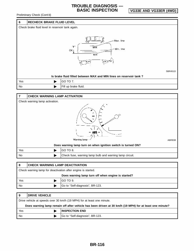
6 RECHECK BRAKE FLUID LEVEL
Check brake fluid level in reservoir tank again.
SBR451D
Is brake fluid filled between MAX and MIN lines on reservoir tank ?
Yes GO TO 7.
No Fill up brake fluid.
7 CHECK WARNING LAMP ACTIVATION
Check warning lamp activation.
ABR838
Does warning lamp turn on when ignition switch is turned ON?
Yes GO TO 8.
No Check fuse, warning lamp bulb and warning lamp circuit.
8 CHECK WARNING LAMP DEACTIVATION
Check warning lamp for deactivation after engine is started.
Does warning lamp turn off when engine is started?
Yes GO TO 9.
No Go to “Self-diagnosis”, BR-123.
9 DRIVE VEHICLE
Drive vehicle at speeds over 30 km/h (19 MPH) for at least one minute.
Does warning lamp remain off after vehicle has been driven at 30 km/h (19 MPH) for at least one minute?
Yes INSPECTION END
No Go to “Self-diagnosis”, BR-123.
TROUBLE DIAGNOSIS —BASIC INSPECTION VG33E AND VG33ER (4WD)
Preliminary Check (Cont’d)
BR-116

ABR882
Ground Circuit Check=NEBR0287
ABS ACTUATOR AND ELECTRIC UNIT GROUNDNEBR0287S01
Check continuity between ABS actuator and electric unit con-nector terminals and ground.
Continuity should exist.
TROUBLE DIAGNOSIS —BASIC INSPECTION VG33E AND VG33ER (4WD)
Ground Circuit Check
BR-117
GI
MA
EM
LC
EC
FE
CL
MT
AT
TF
PD
AX
SU
ST
RS
BT
HA
SC
EL
IDX
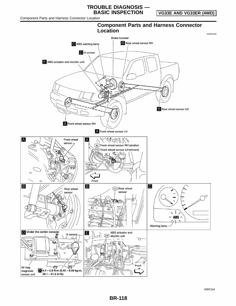
Component Parts and Harness ConnectorLocation
NEBR0288
WBR334
TROUBLE DIAGNOSIS —BASIC INSPECTION VG33E AND VG33ER (4WD)
Component Parts and Harness Connector Location
BR-118

SchematicNEBR0289
WBR373
TROUBLE DIAGNOSIS —BASIC INSPECTION VG33E AND VG33ER (4WD)
Schematic
BR-119
GI
MA
EM
LC
EC
FE
CL
MT
AT
TF
PD
AX
SU
ST
RS
BT
HA
SC
EL
IDX

Wiring Diagram — ABS —NEBR0290
WBR335
TROUBLE DIAGNOSIS —BASIC INSPECTION VG33E AND VG33ER (4WD)
Wiring Diagram — ABS —
BR-120

WBR191
TROUBLE DIAGNOSIS —BASIC INSPECTION VG33E AND VG33ER (4WD)
Wiring Diagram — ABS — (Cont’d)
BR-121
GI
MA
EM
LC
EC
FE
CL
MT
AT
TF
PD
AX
SU
ST
RS
BT
HA
SC
EL
IDX

WBR374
TROUBLE DIAGNOSIS —BASIC INSPECTION VG33E AND VG33ER (4WD)
Wiring Diagram — ABS — (Cont’d)
BR-122

Self-diagnosis (Without CONSULT-II)NEBR0292
FUNCTIONNEBR0292S01
When a problem occurs in the ABS, the warning lamp on theinstrument panel comes on. [To start the self-diagnostic resultsmode, ground the self-diagnostic (check) terminal 9 located onthe data link connector. The location of the malfunction is indi-cated by the warning lamp flashing]
SELF-DIAGNOSIS PROCEDURENEBR0292S02
1. Drive vehicle over 30 km/h (19 MPH) for at least one minute.2. Turn ignition switch OFF.
ABR847
3. Ground terminal 9 of data link connector with a suitable har-ness.
4. Turn ignition switch ON while grounding terminal 9.Do not depress brake pedal.
ABR910
5. After 3.0 seconds, the warning lamp starts flashing to indicatethe malfunction code No. (See NOTE.)
6. Verify the location of the malfunction with the “MalfunctionCode/Symptom Chart”. Refer to BR-125. Then make the nec-essary repairs following the diagnostic procedures.
7. After the malfunctions are repaired, erase the malfunctioncodes stored in the control unit. Refer to “HOW TO ERASESELF-DIAGNOSTIC RESULTS (MALFUNCTION CODES)”,BR-124.
8. Rerun the self-diagnostic results mode to verify that the mal-function codes have been erased.
ABR847
9. Disconnect the data link connector terminal from the ground.The self-diagnostic results mode is now complete.
10. Check warning lamp for deactivation after driving vehicle over30 km/h (19 MPH) for at least one minute.
11. After making certain that warning lamp does not come on, testthe ABS in a safe area to verify that it functions properly.
NOTE:The indication terminates after 5 minutes.However, when the ignition switch is turned from OFF to ON, theindication starts flashing again.
ON BOARD DIAGNOSTIC SYSTEMDESCRIPTION VG33E AND VG33ER (4WD)
Self-diagnosis (Without CONSULT-II)
BR-123
GI
MA
EM
LC
EC
FE
CL
MT
AT
TF
PD
AX
SU
ST
RS
BT
HA
SC
EL
IDX

HOW TO READ SELF-DIAGNOSTIC RESULTS(MALFUNCTION CODES)
=NEBR0292S03
1. Determine the code No. by counting the number of times thewarning lamp flashes on and off.
2. When several malfunctions occur at one time, up to three codenumbers can be stored; the latest malfunction will be indicatedfirst.
3. The indication begins with the start code 12. After that a maxi-mum of three code numbers appear in the order of the lowestto highest. The indication then returns to the start code 12 torepeat (the indication will stay on for five minutes at the most).
4. The “Malfunction Code/Symptom Chart” is given on pageBR-125.
SBR457D
ABR256
HOW TO ERASE SELF-DIAGNOSTIC RESULTS(MALFUNCTION CODES)
NEBR0292S04
1. Disconnect the check terminal from ground (ABS warning lampwill stay lit).
2. Within 12.5 seconds, ground the check terminal three times.Each terminal ground must last more than 1 second. The ABSwarning lamp goes out after the erase operation has beencompleted.
3. Perform self-diagnosis again. Refer to “Self-diagnosis”,BR-123. Only the startcode should appear, no malfunctioncodes.
ON BOARD DIAGNOSTIC SYSTEMDESCRIPTION VG33E AND VG33ER (4WD)
Self-diagnosis (Without CONSULT-II) (Cont’d)
BR-124
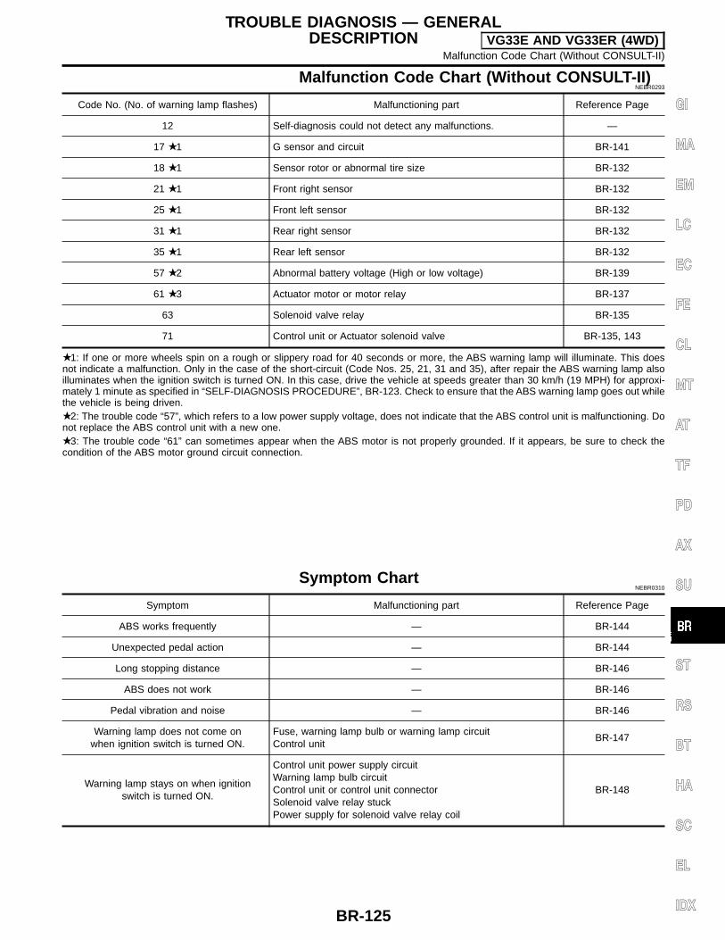
Malfunction Code Chart (Without CONSULT-II)NEBR0293
Code No. (No. of warning lamp flashes) Malfunctioning part Reference Page
12 Self-diagnosis could not detect any malfunctions. —
17 1 G sensor and circuit BR-141
18 1 Sensor rotor or abnormal tire size BR-132
21 1 Front right sensor BR-132
25 1 Front left sensor BR-132
31 1 Rear right sensor BR-132
35 1 Rear left sensor BR-132
57 2 Abnormal battery voltage (High or low voltage) BR-139
61 3 Actuator motor or motor relay BR-137
63 Solenoid valve relay BR-135
71 Control unit or Actuator solenoid valve BR-135, 143
1: If one or more wheels spin on a rough or slippery road for 40 seconds or more, the ABS warning lamp will illuminate. This doesnot indicate a malfunction. Only in the case of the short-circuit (Code Nos. 25, 21, 31 and 35), after repair the ABS warning lamp alsoilluminates when the ignition switch is turned ON. In this case, drive the vehicle at speeds greater than 30 km/h (19 MPH) for approxi-mately 1 minute as specified in “SELF-DIAGNOSIS PROCEDURE”, BR-123. Check to ensure that the ABS warning lamp goes out whilethe vehicle is being driven. 2: The trouble code “57”, which refers to a low power supply voltage, does not indicate that the ABS control unit is malfunctioning. Donot replace the ABS control unit with a new one. 3: The trouble code “61” can sometimes appear when the ABS motor is not properly grounded. If it appears, be sure to check thecondition of the ABS motor ground circuit connection.
Symptom ChartNEBR0310
Symptom Malfunctioning part Reference Page
ABS works frequently — BR-144
Unexpected pedal action — BR-144
Long stopping distance — BR-146
ABS does not work — BR-146
Pedal vibration and noise — BR-146
Warning lamp does not come onwhen ignition switch is turned ON.
Fuse, warning lamp bulb or warning lamp circuitControl unit
BR-147
Warning lamp stays on when ignitionswitch is turned ON.
Control unit power supply circuitWarning lamp bulb circuitControl unit or control unit connectorSolenoid valve relay stuckPower supply for solenoid valve relay coil
BR-148
TROUBLE DIAGNOSIS — GENERALDESCRIPTION VG33E AND VG33ER (4WD)
Malfunction Code Chart (Without CONSULT-II)
BR-125
GI
MA
EM
LC
EC
FE
CL
MT
AT
TF
PD
AX
SU
ST
RS
BT
HA
SC
EL
IDX
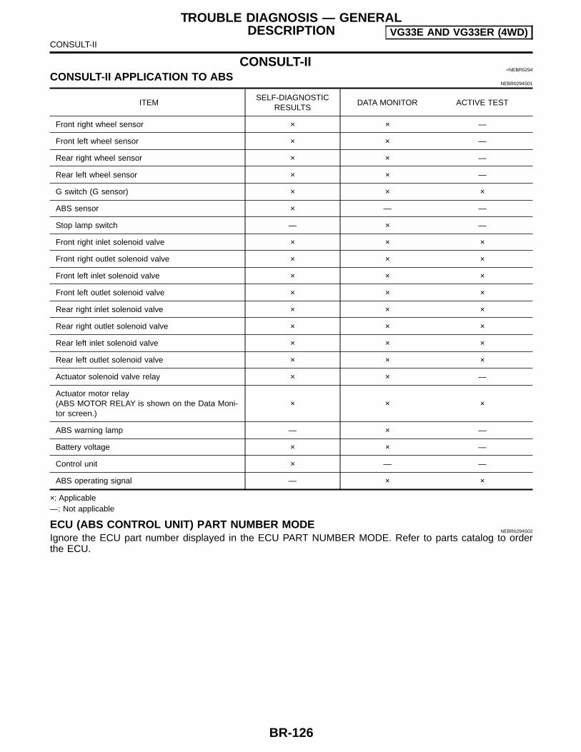
CONSULT-II=NEBR0294
CONSULT-II APPLICATION TO ABSNEBR0294S01
ITEMSELF-DIAGNOSTIC
RESULTSDATA MONITOR ACTIVE TEST
Front right wheel sensor × × —
Front left wheel sensor × × —
Rear right wheel sensor × × —
Rear left wheel sensor × × —
G switch (G sensor) × × ×
ABS sensor × — —
Stop lamp switch — × —
Front right inlet solenoid valve × × ×
Front right outlet solenoid valve × × ×
Front left inlet solenoid valve × × ×
Front left outlet solenoid valve × × ×
Rear right inlet solenoid valve × × ×
Rear right outlet solenoid valve × × ×
Rear left inlet solenoid valve × × ×
Rear left outlet solenoid valve × × ×
Actuator solenoid valve relay × × —
Actuator motor relay(ABS MOTOR RELAY is shown on the Data Moni-tor screen.)
× × ×
ABS warning lamp — × —
Battery voltage × × —
Control unit × — —
ABS operating signal — × ×
×: Applicable—: Not applicable
ECU (ABS CONTROL UNIT) PART NUMBER MODENEBR0294S02
Ignore the ECU part number displayed in the ECU PART NUMBER MODE. Refer to parts catalog to orderthe ECU.
TROUBLE DIAGNOSIS — GENERALDESCRIPTION VG33E AND VG33ER (4WD)
CONSULT-II
BR-126
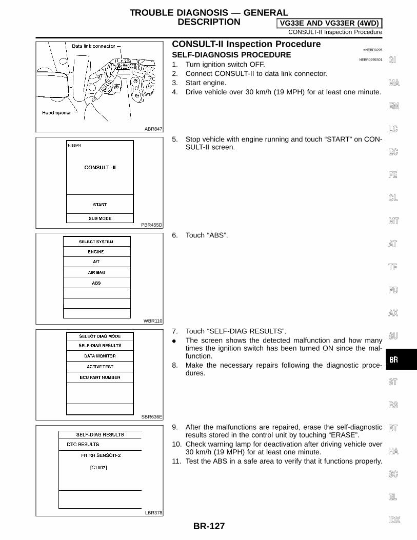
ABR847
CONSULT-II Inspection Procedure=NEBR0295
SELF-DIAGNOSIS PROCEDURENEBR0295S01
1. Turn ignition switch OFF.2. Connect CONSULT-II to data link connector.3. Start engine.4. Drive vehicle over 30 km/h (19 MPH) for at least one minute.
PBR455D
5. Stop vehicle with engine running and touch “START” on CON-SULT-II screen.
WBR110
6. Touch “ABS”.
SBR636E
7. Touch “SELF-DIAG RESULTS”. The screen shows the detected malfunction and how many
times the ignition switch has been turned ON since the mal-function.
8. Make the necessary repairs following the diagnostic proce-dures.
LBR378
9. After the malfunctions are repaired, erase the self-diagnosticresults stored in the control unit by touching “ERASE”.
10. Check warning lamp for deactivation after driving vehicle over30 km/h (19 MPH) for at least one minute.
11. Test the ABS in a safe area to verify that it functions properly.
TROUBLE DIAGNOSIS — GENERALDESCRIPTION VG33E AND VG33ER (4WD)
CONSULT-II Inspection Procedure
BR-127
GI
MA
EM
LC
EC
FE
CL
MT
AT
TF
PD
AX
SU
ST
RS
BT
HA
SC
EL
IDX

SELF-DIAGNOSTIC RESULTS MODE=NEBR0295S02
Diagnostic item Diagnosed condition Diagnostic item is detected when ...Reference
Page
FR RH SENSOR-2 1[C1107]
Open Circuit for front right wheel sensor is open.
(An abnormally high input voltage is entered.)BR-132
FR LH SENSOR-2 1[C1108]
Open Circuit for front left wheel sensor is open.
(An abnormally high input voltage is entered.)BR-132
RR RH SENSOR-2 1[C1105]
Open Circuit for rear right sensor is open.
(An abnormally high input voltage is entered.)BR-132
RR LH SENSOR-2 1[C1106]
Open Circuit for rear left sensor is open.
(An abnormally high input voltage is entered.) BR-132
FR RH SENSOR-1 1[C1103]
Short Circuit for front right wheel sensor is shorted.
(An abnormally low input voltage is entered.)BR-132
FR LH SENSOR-1 1[C1104]
Short Circuit for front left wheel sensor is shorted.
(An abnormally low input voltage is entered.)BR-132
RR RH SENSOR-1 1[C1101]
Short Circuit for rear right sensor is shorted.
(An abnormally low input voltage is entered.)BR-132
RR LH SENSOR-1 1[C1102]
Short Circuit for rear left sensor is shorted.
(An abnormally low input voltage is entered.) BR-132
ABS SENSOR 1[C1115]
Abnormal signal Teeth damage on sensor rotor or improper installation of
wheel sensor.(Abnormal wheel sensor signal is entered.)
BR-132
MAIN RELAY[C1114]
Abnormal
Actuator solenoid valve relay is ON, even if control unit sendsoff signal.
Actuator solenoid valve relay is OFF, even if control unitsends on signal.
BR-135
PUMP MOTOR[C1111]
Abnormal Circuit for ABS motor relay is open or shorted. Circuit for actuator motor is open or shorted. Actuator motor relay is stuck.
BR-137
BATTERY VOLTAGE[ABNORMAL][C1109]
High or low Power source voltage supplied to ABS control unit is abnor-
mally low. BR-139
CONTROLLER FAIL-URE[C1110]
Control unit Function of calculation in ABS control unit has failed. BR-143
Solenoid valve open/short
Circuit for solenoid valve is open or shorted. (An abnormallyhigh or low output voltage is entered.)
BR-135
G-SENSOR[C1113] 2
Abnormal signal G sensor circuit is open or shorted.
BR-141
ABNORMAL TIRESIZE[C1112]
Abnormal Sensor rotor damaged or incorrect tire size.
BR-132
1: If one or more wheels spin on a rough or slippery road for 40 seconds or more, the ABS warning lamp will illuminate. This doesnot indicate a malfunction. Only in the case of the short-circuit (Code Nos. C1101, C1102, C1103 and C1104), after repair the ABSwarning lamp also illuminates when the ignition switch is turned ON. In this case, drive the vehicle at speeds greater than 30 km/h (19MPH) for approx. 1 minute as specified in “SELF-DIAGNOSIS PROCEDURE”, BR-123. Check to ensure that the ABS warning lampgoes out.
TROUBLE DIAGNOSIS — GENERALDESCRIPTION VG33E AND VG33ER (4WD)
CONSULT-II Inspection Procedure (Cont’d)
BR-128

PBR455D
DATA MONITOR PROCEDURE=NEBR0295S03
1. Turn ignition switch OFF.2. Connect CONSULT-II to data link connector.3. Turn ignition switch ON.4. Touch “START” on CONSULT-II screen.
WBR110
5. Touch “ABS”.
SBR636E
6. Touch “DATA MONITOR”.
SBR637E
7. Touch “SETTING” on “SELECT MONITOR ITEM” screen.
TROUBLE DIAGNOSIS — GENERALDESCRIPTION VG33E AND VG33ER (4WD)
CONSULT-II Inspection Procedure (Cont’d)
BR-129
GI
MA
EM
LC
EC
FE
CL
MT
AT
TF
PD
AX
SU
ST
RS
BT
HA
SC
EL
IDX
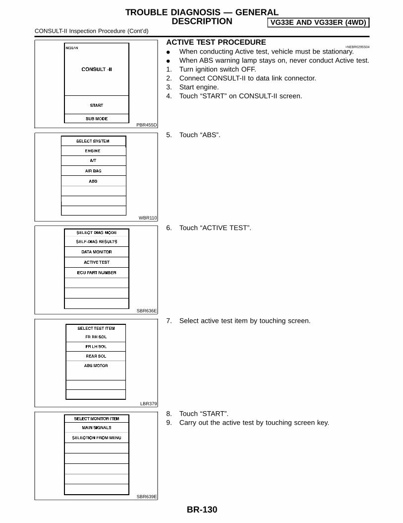
PBR455D
ACTIVE TEST PROCEDURE=NEBR0295S04
When conducting Active test, vehicle must be stationary. When ABS warning lamp stays on, never conduct Active test.1. Turn ignition switch OFF.2. Connect CONSULT-II to data link connector.3. Start engine.4. Touch “START” on CONSULT-II screen.
WBR110
5. Touch “ABS”.
SBR636E
6. Touch “ACTIVE TEST”.
LBR379
7. Select active test item by touching screen.
SBR639E
8. Touch “START”.9. Carry out the active test by touching screen key.
TROUBLE DIAGNOSIS — GENERALDESCRIPTION VG33E AND VG33ER (4WD)
CONSULT-II Inspection Procedure (Cont’d)
BR-130

DATA MONITOR MODE=NEBR0295S05
MONITOR ITEM CONDITION SPECIFICATION
FR RH SENSORFR LH SENSORRR RH SENSORRR LH SENSOR
Drive vehicle.(Each wheel is rotating.)
Wheel speed signal(Almost the same speed as speedometer.)
STOP LAMP SW Brake is depressed.Depress the pedal: ONRelease the pedal: OFF
DECEL G-SENVehicle is driven.Vehicle is stopped.Brake is applied.
During sudden braking while driving on high µ roads (asphaltroads, etc.): OFFWhile vehicle is stopped or during constant-speed driving: ON
FR RH IN SOLFR RH OUT SOLFR LH IN SOLFR LH OUT SOLRR RH IN SOLRR RH OUT SOLRR LH IN SOLRR LH OUT SOL
1. Drive vehicle at speedsover 30 km/h (19 MPH) for atleast 1 minute.2. Engine is running.
Operating conditions for each solenoid valve are indicated. ABS isnot operating: OFF
MOTOR RELAYABS is not operating: OFFABS is operating: ON
WARNING LAMP Ignition switch is ON orengine is running.
ABS warning lamp is turned on: ONABS warning lamp is turned off: OFF
BATTERY VOLT Power supply voltage for control unit
ACTIVE TEST MODENEBR0295S06
TEST ITEM CONDITION JUDGEMENT
FR RH SOLFR LH SOLRR RH SOLRR LH SOL Engine is running.
Brake fluid pressure control operation
IN SOL OUT SOL
UP (Increase): OFF OFF
KEEP (Hold): ON OFF
DOWN (Decrease): ON ON
ABS MOTORABS actuator motorON: Motor runs (ABS motor relay ON)OFF: Motor stops (ABS motor relay OFF)
NOTE:Active test will automatically stop ten seconds after the test starts. (TEST IS STOPPED is displayed.)
TROUBLE DIAGNOSIS — GENERALDESCRIPTION VG33E AND VG33ER (4WD)
CONSULT-II Inspection Procedure (Cont’d)
BR-131
GI
MA
EM
LC
EC
FE
CL
MT
AT
TF
PD
AX
SU
ST
RS
BT
HA
SC
EL
IDX

Wheel Sensor or RotorDIAGNOSTIC PROCEDURE
NEBR0296
With CONSULT-II: Malfunction code No. C1101, C1102,C1103, C1104, C1105, C1106, C1107, C1108, C1112 or C1115
Without CONSULT-II: Malfunction code No. 21, 25, 31, 35, or18NOTE:Wheel position should be distinguished by code No. except codeNo. 18 (sensor rotor).
1 INSPECTION START
Wheel sensor inspection
WBR352
GO TO 2.
2 CHECK CONNECTOR
1. Disconnect connectors from ABS actuator and electric unit and wheel sensor of malfunction code No. Check terminalsfor damage or loose connection. Then reconnect connectors.
2. Carry out “Self-diagnosis” again. Refer to BR-123.
Does warning lamp activate again?
Yes GO TO 3.
No INSPECTION END
3 CHECK TIRE
Check for inflation pressure, wear and size of each tire. (See NOTE)
Are tire pressure and size correct and is tire wear within specifications?
Yes GO TO 4.
No Adjust tire pressure or replace tire(s). (See NOTE)
TROUBLE DIAGNOSES FORSELF-DIAGNOSTIC ITEMS VG33E AND VG33ER (4WD)
Wheel Sensor or Rotor
BR-132

4 CHECK WHEEL BEARING
Check wheel bearing axial end play. (See NOTE)
Is wheel bearing axial end play within specifications? Refer to AX-5, “FRONT AXLE” and AX-28, “REAR AXLE”.
Yes GO TO 5.
No Check wheel bearing. Refer to AX-13, “FRONT AXLE” and AX-33, “REAR AXLE”.
5 CHECK WIRING HARNESS SHORT
1. Disconnect ABS actuator and electric unit connector E39 and ABS sensor connectors E2, E16, and C6.2. Check resistance between indicated wiring harness connectors/terminals and ground
Front RH wheelConnector E2, terminals 4 and 5Front LH wheelConnector E16, terminals 6 and 7Rear RH wheelConnector C6, terminals 1 and 2Rear LH wheelConnector C6, terminals 8 and 9
LBR336
0Ω:NG∞Ω:OK
Are resistance values OK?
Yes GO TO 6.
No Repair/replace harness or connectors.
TROUBLE DIAGNOSES FORSELF-DIAGNOSTIC ITEMS VG33E AND VG33ER (4WD)
Wheel Sensor or Rotor (Cont’d)
BR-133
GI
MA
EM
LC
EC
FE
CL
MT
AT
TF
PD
AX
SU
ST
RS
BT
HA
SC
EL
IDX
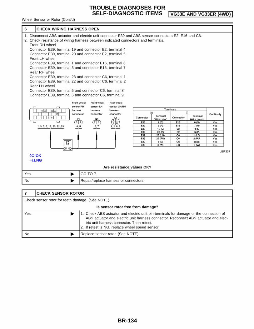
6 CHECK WIRING HARNESS OPEN
1. Disconnect ABS actuator and electric unit connector E39 and ABS sensor connectors E2, E16 and C6.2. Check resistance of wiring harness between indicated connectors and terminals.
Front RH wheelConnector E39, terminal 19 and connector E2, terminal 4Connector E39, terminal 20 and connector E2, terminal 5Front LH wheelConnector E39, terminal 1 and connector E16, terminal 6Connector E39, terminal 3 and connector E16, terminal 7Rear RH wheelConnector E39, terminal 23 and connector C6, terminal 1Connector E39, terminal 22 and connector C6, terminal 2Rear LH wheelConnector E39, terminal 5 and connector C6, terminal 8Connector E39, terminal 6 and connector C6, terminal 9
LBR337
0Ω:OK∞Ω:NG
Are resistance values OK?
Yes GO TO 7.
No Repair/replace harness or connectors.
7 CHECK SENSOR ROTOR
Check sensor rotor for teeth damage. (See NOTE)
Is sensor rotor free from damage?
Yes 1. Check ABS actuator and electric unit pin terminals for damage or the connection ofABS actuator and electric unit harness connector. Reconnect ABS actuator and elec-tric unit harness connector. Then retest.
2. If retest is NG, replace wheel speed sensor.
No Replace sensor rotor. (See NOTE)
TROUBLE DIAGNOSES FORSELF-DIAGNOSTIC ITEMS VG33E AND VG33ER (4WD)
Wheel Sensor or Rotor (Cont’d)
BR-134
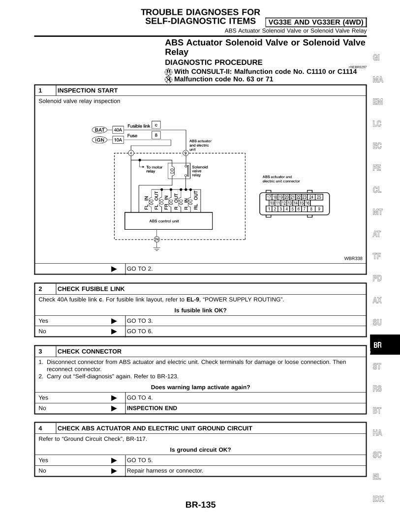
ABS Actuator Solenoid Valve or Solenoid ValveRelayDIAGNOSTIC PROCEDURE
=NEBR0297
With CONSULT-II: Malfunction code No. C1110 or C1114Malfunction code No. 63 or 71
1 INSPECTION START
Solenoid valve relay inspection
WBR338
GO TO 2.
2 CHECK FUSIBLE LINK
Check 40A fusible link c. For fusible link layout, refer to EL-9, “POWER SUPPLY ROUTING”.
Is fusible link OK?
Yes GO TO 3.
No GO TO 6.
3 CHECK CONNECTOR
1. Disconnect connector from ABS actuator and electric unit. Check terminals for damage or loose connection. Thenreconnect connector.
2. Carry out “Self-diagnosis” again. Refer to BR-123.
Does warning lamp activate again?
Yes GO TO 4.
No INSPECTION END
4 CHECK ABS ACTUATOR AND ELECTRIC UNIT GROUND CIRCUIT
Refer to “Ground Circuit Check”, BR-117.
Is ground circuit OK?
Yes GO TO 5.
No Repair harness or connector.
TROUBLE DIAGNOSES FORSELF-DIAGNOSTIC ITEMS VG33E AND VG33ER (4WD)
ABS Actuator Solenoid Valve or Solenoid Valve Relay
BR-135
GI
MA
EM
LC
EC
FE
CL
MT
AT
TF
PD
AX
SU
ST
RS
BT
HA
SC
EL
IDX

5 CHECK SOLENOID VALVE POWER SUPPLY CIRCUIT
1. Disconnect ABS actuator and electric unit connector.2. Check voltage between ABS actuator and electric unit connector E39 terminal 9 and ground.
ABR887
Does battery voltage exist?
Yes Replace ABS actuator and electric unit.
No Check the following.If NG, repair harness or connectors. Harness connector E39 Harness for open or short between ABS actuator and electric unit and fusible link
6 REPLACE FUSIBLE LINK
Replace fusible link.
Does the fuse blow out when ignition switch is turned ON?
Yes GO TO 7.
No INSPECTION END
7 CHECK SOLENOID VALVE RELAY POWER SUPPLY CIRCUIT FOR SHORT
1. Disconnect battery cable and ABS actuator and electric unit connector.2. Check continuity between ABS actuator and electric unit connector E39 terminal 9 and ground.
ABR888
Continuity should not exist.
Does continuity exist?
Yes Check the following.If NG, repair harness or connector. Harness connector E39 Harness for open or short between ABS actuator and electric unit and fusible link
No Replace ABS actuator and electric unit.
TROUBLE DIAGNOSES FORSELF-DIAGNOSTIC ITEMS VG33E AND VG33ER (4WD)
ABS Actuator Solenoid Valve or Solenoid Valve Relay (Cont’d)
BR-136
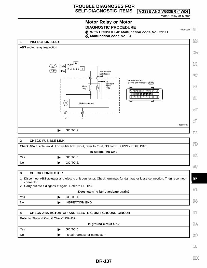
Motor Relay or MotorDIAGNOSTIC PROCEDURE
=NEBR0298
With CONSULT-II: Malfunction code No. C1111Malfunction code No. 61
1 INSPECTION START
ABS motor relay inspection
ABR889
GO TO 2.
2 CHECK FUSIBLE LINK
Check 40A fusible link d. For fusible link layout, refer to EL-9, “POWER SUPPLY ROUTING”.
Is fusible link OK?
Yes GO TO 3.
No GO TO 6.
3 CHECK CONNECTOR
1. Disconnect ABS actuator and electric unit connector. Check terminals for damage or loose connection. Then reconnectconnector.
2. Carry out “Self-diagnosis” again. Refer to BR-123.
Does warning lamp activate again?
Yes GO TO 4.
No INSPECTION END
4 CHECK ABS ACTUATOR AND ELECTRIC UNIT GROUND CIRCUIT
Refer to “Ground Circuit Check”, BR-117.
Is ground circuit OK?
Yes GO TO 5.
No Repair harness or connector.
TROUBLE DIAGNOSES FORSELF-DIAGNOSTIC ITEMS VG33E AND VG33ER (4WD)
Motor Relay or Motor
BR-137
GI
MA
EM
LC
EC
FE
CL
MT
AT
TF
PD
AX
SU
ST
RS
BT
HA
SC
EL
IDX

5 CHECK MOTOR RELAY POWER SUPPLY CIRCUIT
1. Disconnect ABS actuator and electric unit connector.2. Check voltage between ABS actuator and electric unit connector E39 terminal 25 and ground.
ABR890
Does battery voltage exist?
Yes Replace ABS actuator and electric unit.
No Check the following.If NG, repair harness or connector. Harness connector E39 Harness for open or short between ABS actuator and electric unit and fusible link
6 REPLACE FUSIBLE LINK
Replace fusible link.
Does the fusible link blow out when ignition switch is turned ON?
Yes GO TO 7.
No INSPECTION END
7 CHECK ABS ACTUATOR MOTOR POWER SUPPLY CIRCUIT FOR SHORT
1. Disconnect battery cable and ABS actuator and electric unit connector.2. Check continuity between ABS actuator and electric unit connector E39 terminal 25 and ground.
ABR891
Continuity should not exist.
Does continuity exist?
Yes Check the following.If NG, repair harness or connector. Harness connector E39 Harness for open or short between ABS actuator and electric unit and fusible link
No Replace ABS actuator and electric unit.
TROUBLE DIAGNOSES FORSELF-DIAGNOSTIC ITEMS VG33E AND VG33ER (4WD)
Motor Relay or Motor (Cont’d)
BR-138

Low VoltageDIAGNOSTIC PROCEDURE
NEBR0299
With CONSULT-II: Malfunction code No. C1109Malfunction code No. 57
1 INSPECTION START
ABS actuator and electric unit power supply and ground circuit inspection
ABR892
GO TO 2.
2 CHECK FUSE
Check 10A fuse No. 8. For fuse layout, refer to EL-9, “POWER SUPPLY ROUTING”.
Is fuse OK?
Yes GO TO 3.
No GO TO 6.
3 CHECK CONNECTOR
1. Disconnect ABS actuator and electric unit connector. Check terminals for damage or loose connections. Then recon-nect connector.
2. Carry out “Self-diagnosis” again. Refer to BR-123.
Does warning lamp activate again?
Yes GO TO 4.
No INSPECTION END
4 CHECK ABS ACTUATOR AND ELECTRIC UNIT GROUND CIRCUIT
Refer to “Ground Circuit Check”, BR-117.
Is ground circuit OK?
Yes GO TO 5.
No Repair harness or connector.
TROUBLE DIAGNOSES FORSELF-DIAGNOSTIC ITEMS VG33E AND VG33ER (4WD)
Low Voltage
BR-139
GI
MA
EM
LC
EC
FE
CL
MT
AT
TF
PD
AX
SU
ST
RS
BT
HA
SC
EL
IDX
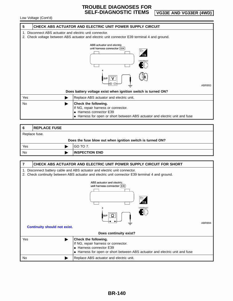
5 CHECK ABS ACTUATOR AND ELECTRIC UNIT POWER SUPPLY CIRCUIT
1. Disconnect ABS actuator and electric unit connector.2. Check voltage between ABS actuator and electric unit connector E39 terminal 4 and ground.
ABR893
Does battery voltage exist when ignition switch is turned ON?
Yes Replace ABS actuator and electric unit.
No Check the following.If NG, repair harness or connector. Harness connector E39 Harness for open or short between ABS actuator and electric unit and fuse
6 REPLACE FUSE
Replace fuse.
Does the fuse blow out when ignition switch is turned ON?
Yes GO TO 7.
No INSPECTION END
7 CHECK ABS ACTUATOR AND ELECTRIC UNIT POWER SUPPLY CIRCUIT FOR SHORT
1. Disconnect battery cable and ABS actuator and electric unit connector.2. Check continuity between ABS actuator and electric unit connector E39 terminal 4 and ground.
ABR894
Continuity should not exist.
Does continuity exist?
Yes Check the following.If NG, repair harness or connector. Harness connector E39 Harness for open or short between ABS actuator and electric unit and fuse
No Replace ABS actuator and electric unit.
TROUBLE DIAGNOSES FORSELF-DIAGNOSTIC ITEMS VG33E AND VG33ER (4WD)
Low Voltage (Cont’d)
BR-140
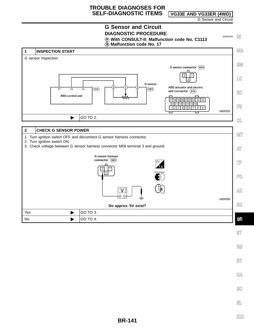
G Sensor and CircuitDIAGNOSTIC PROCEDURE
NEBR0300
With CONSULT-II: Malfunction code No. C1113Malfunction code No. 17
1 INSPECTION START
G sensor inspection
ABR895
GO TO 2.
2 CHECK G SENSOR POWER
1. Turn ignition switch OFF and disconnect G sensor harness connector.2. Turn ignition switch ON.3. Check voltage between G sensor harness connector M69 terminal 3 and ground.
ABR896
Do approx. 5V exist?
Yes GO TO 3.
No GO TO 4.
TROUBLE DIAGNOSES FORSELF-DIAGNOSTIC ITEMS VG33E AND VG33ER (4WD)
G Sensor and Circuit
BR-141
GI
MA
EM
LC
EC
FE
CL
MT
AT
TF
PD
AX
SU
ST
RS
BT
HA
SC
EL
IDX

3 CHECK G SENSOR
1. Turn ignition switch OFF.2. Remove G sensor from bracket.3. Reconnect harness connector to G sensor and hold sensor in same attitude/position as when installed in vehicle. Check voltage between G sensor connector M69 terminal 1 and ground for the following tests.There should be approx. 2.5V.4. Turn sensor 90° with connector point up. There should be approx. 3.7V.5. Turn sensor 180° with connector pointing down. There should be approx. 1.3V.
ABR897
Were the voltage readings correct for steps 3, 4 and 5?
Yes GO TO 4.
No Replace G Sensor.
4 CHECK G SENSOR CIRCUIT
1. Disconnect ABS actuator and electric unit connector.2. Check continuity from G sensor connector M69 terminal 3 to ABS actuator and electric unit connector E39 terminal 14.3. Check continuity from G sensor connector M69 terminal 1 to ABS actuator and electric unit connector E39 terminal 13.4. Check continuity from G sensor connector M69 terminal 2 to ABS actuator and electric unit connector E39 terminal 17.
ABR898
Does continuity exist?
Yes Replace ABS actuator and electric unit.
No Repair harness or connector.
TROUBLE DIAGNOSES FORSELF-DIAGNOSTIC ITEMS VG33E AND VG33ER (4WD)
G Sensor and Circuit (Cont’d)
BR-142

Control UnitDIAGNOSTIC PROCEDURE
=NEBR0301
With CONSULT-II: Malfunction code No. C1110Malfunction code No. 71
1 INSPECTION START
ABS actuator and electric unit power supply and ground circuit inspection
ABR899
GO TO 2.
2 CHECK CONNECTOR
1. Disconnect ABS actuator and electric unit connector.Check terminals for damage or loose connection. Then reconnect connector.
2. Carry out self-diagnosis again.
Does warning lamp activate again?
Yes GO TO 3.
No INSPECTION END
3 CHECK ABS ACTUATOR AND ELECTRIC UNIT POWER SUPPLY CIRCUIT
Check voltage. Refer to Test No. 5, “Low Voltage”, BR-139.
Does battery voltage exist when ignition switch is turned ON?
Yes GO TO 4.
No Repair.
4 CHECK WARNING LAMP INDICATION
Does warning lamp indicate code No. 71 again?
Yes or No
Yes Replace ABS actuator and electric unit.
No Inspect the system according to the code No.
TROUBLE DIAGNOSES FORSELF-DIAGNOSTIC ITEMS VG33E AND VG33ER (4WD)
Control Unit
BR-143
GI
MA
EM
LC
EC
FE
CL
MT
AT
TF
PD
AX
SU
ST
RS
BT
HA
SC
EL
IDX
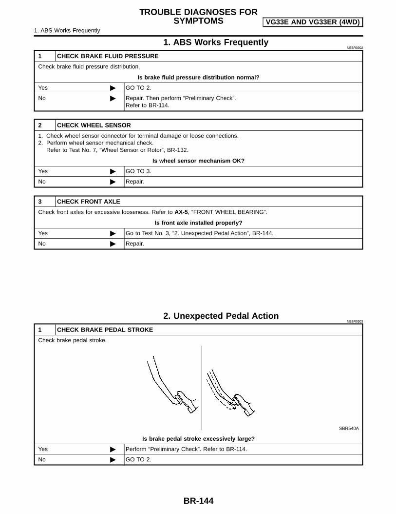
1. ABS Works FrequentlyNEBR0302
1 CHECK BRAKE FLUID PRESSURE
Check brake fluid pressure distribution.
Is brake fluid pressure distribution normal?
Yes GO TO 2.
No Repair. Then perform “Preliminary Check”.Refer to BR-114.
2 CHECK WHEEL SENSOR
1. Check wheel sensor connector for terminal damage or loose connections.2. Perform wheel sensor mechanical check.
Refer to Test No. 7, “Wheel Sensor or Rotor”, BR-132.
Is wheel sensor mechanism OK?
Yes GO TO 3.
No Repair.
3 CHECK FRONT AXLE
Check front axles for excessive looseness. Refer to AX-5, “FRONT WHEEL BEARING”.
Is front axle installed properly?
Yes Go to Test No. 3, “2. Unexpected Pedal Action”, BR-144.
No Repair.
2. Unexpected Pedal ActionNEBR0303
1 CHECK BRAKE PEDAL STROKE
Check brake pedal stroke.
SBR540A
Is brake pedal stroke excessively large?
Yes Perform “Preliminary Check”. Refer to BR-114.
No GO TO 2.
TROUBLE DIAGNOSES FORSYMPTOMS VG33E AND VG33ER (4WD)
1. ABS Works Frequently
BR-144

2 CHECK MECHANICAL BRAKE SYSTEM PERFORMANCE
Disconnect ABS actuator and electric unit connector and check whether brake is effective.
Does brake system function properly when brake pedal is depressed?
Yes GO TO 3.
No Perform “Preliminary Check”. Refer to BR-114.
3 CHECK WARNING LAMP INDICATION
Ensure warning lamp remains off while driving.
ABR838
Is warning lamp turned off?
Yes GO TO 4.
No Carry out “Self-diagnosis”. Refer to BR-123.
4 CHECK WHEEL SENSOR
1. Check wheel sensor connector for terminal damage or loose connection.2. Perform wheel sensor mechanical check. Refer to Test No. 7, “Wheel Sensor or Rotor”, BR-132.
Is wheel sensor mechanism OK?
Yes Check ABS actuator and electric unit pin terminals for damage or the connection of ABSactuator and electric unit harness connector.Reconnect ABS actuator and electric unit harness connector.Then retest.
No Repair.
TROUBLE DIAGNOSES FORSYMPTOMS VG33E AND VG33ER (4WD)
2. Unexpected Pedal Action (Cont’d)
BR-145
GI
MA
EM
LC
EC
FE
CL
MT
AT
TF
PD
AX
SU
ST
RS
BT
HA
SC
EL
IDX

3. Long Stopping Distance=NEBR0304
1 CHECK MECHANICAL BRAKE SYSTEM PERFORMANCE
Disconnect ABS actuator and electric unit connector and check whether stopping distance is still long.
Does brake system function properly when brake pedal is depressed?
Yes Perform “Preliminary Check”, BR-114 and air bleeding (if necessary).
No Go to Test No 3, “2. Unexpected Pedal Action”, BR-144.
NOTE:Stopping distance may be longer for vehicles without ABS whenroad condition is slippery.
4. ABS Does Not WorkNEBR0305
1 CHECK WARNING LAMP INDICATION
Does the ABS warning lamp activate?
Yes or No
Yes Carry out “Self-diagnosis”. Refer to BR-123.
No Go to Test No. 3, “2. Unexpected Pedal Action”, BR-144.
NOTE:ABS does not work when vehicle speed is under 10 km/h (6 MPH).
5. Pedal Vibration and NoiseNEBR0306
1 INSPECTION START
Pedal vibration and noise inspection
SAT797A
NOTE:ABS may operate and cause vibration under any of the following conditions. Applying brake gradually when shifting or operating clutch. Low friction (slippery) road. High speed cornering. Driving over bumps and pot holes. Engine speed is over 5,000 rpm with vehicle stopped.
GO TO 2.
TROUBLE DIAGNOSES FORSYMPTOMS VG33E AND VG33ER (4WD)
3. Long Stopping Distance
BR-146

2 CHECK SYMPTOM
1. Apply brake.2. Start engine.
Does the symptom appear only when engine is started?
Yes Carry out “Self-diagnosis”. Refer to BR-123.
No Go to Test No. 3, “2. Unexpected Pedal Action”, BR-144.
6. Warning Lamp Does Not Come On WhenIgnition Switch Is Turned On
NEBR0307
1 INSPECTION START
Warning lamp circuit inspection
WBR375
GO TO 2.
2 CHECK FUSE
Check 10A fuse No. 11. For fuse layout, refer to EL-9, “POWER SUPPLY ROUTING”.
Is fuse OK?
Yes GO TO 3.
No Replace fuse.
3 CHECK WARNING LAMP ACTIVATE
Disconnect ABS actuator and electric unit connector.
ABR838
Does the warning lamp activate?
Yes Replace ABS actuator and electric unit.
No GO TO 4.
TROUBLE DIAGNOSES FORSYMPTOMS VG33E AND VG33ER (4WD)
5. Pedal Vibration and Noise (Cont’d)
BR-147
GI
MA
EM
LC
EC
FE
CL
MT
AT
TF
PD
AX
SU
ST
RS
BT
HA
SC
EL
IDX

4 CHECK HARNESS FOR SHORT
1. Disconnect ABS actuator and electric unit connector E39 and combination meter connector M38.2. Check continuity between ABS actuator and electric unit connector E39 (body side) terminal 16 (L/W) and ground.
LBR152
Continuity should not exist.
Does continuity exist?
Yes Repair harness or connectors.
No Check combination meter.Refer to EL-84, “WARNING LAMPS”.
7. Warning Lamp Stays On When IgnitionSwitch Is Turned On
NEBR0308
1 INSPECTION START
ABS control unit inspection
WBR376
GO TO 2.
2 CHECK FUSE
Check 10A fuse No. 8. For fuse layout, refer to EL-9, “POWER SUPPLY ROUTING”.
Is fuse OK?
Yes GO TO 3.
No GO TO 8.
TROUBLE DIAGNOSES FORSYMPTOMS VG33E AND VG33ER (4WD)
6. Warning Lamp Does Not Come On When Ignition Switch Is Turned On (Cont’d)
BR-148

3 CHECK HARNESS CONNECTOR
Check ABS actuator and electric unit pin terminals for damage or bad connection of ABS actuator and electric unit harnessconnector. Reconnect ABS actuator and electric unit harness connector. Then retest.
Does warning lamp stay on when ignition switch is turned ON?
Yes GO TO 4.
No INSPECTION END
4 CHECK ABS ACTUATOR AND ELECTRIC UNIT GROUND CIRCUIT
Refer to “Ground Circuit Check”, BR-117.
Is ground circuit OK?
Yes GO TO 5.
No Repair harness or connector.
5 CHECK ABS ACTUATOR AND ELECTRIC UNIT POWER SUPPLY CIRCUIT
1. Disconnect ABS actuator and electric unit connector.2. Check voltage between ABS actuator and electric unit connector E39 terminal 4 (B/P) and ground.
ABR893
Does battery voltage exist when ignition switch is turned ON?
Yes GO TO 6.
No Check the following.If NG, repair harness or connector. Harness connector E39 Harness for open or short between ABS actuator and electric unit and fuse
TROUBLE DIAGNOSES FORSYMPTOMS VG33E AND VG33ER (4WD)7. Warning Lamp Stays On When Ignition Switch Is Turned On (Cont’d)
BR-149
GI
MA
EM
LC
EC
FE
CL
MT
AT
TF
PD
AX
SU
ST
RS
BT
HA
SC
EL
IDX
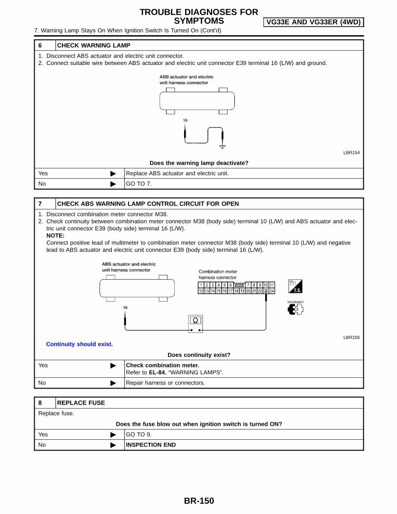
6 CHECK WARNING LAMP
1. Disconnect ABS actuator and electric unit connector.2. Connect suitable wire between ABS actuator and electric unit connector E39 terminal 16 (L/W) and ground.
LBR154
Does the warning lamp deactivate?
Yes Replace ABS actuator and electric unit.
No GO TO 7.
7 CHECK ABS WARNING LAMP CONTROL CIRCUIT FOR OPEN
1. Disconnect combination meter connector M38.2. Check continuity between combination meter connector M38 (body side) terminal 10 (L/W) and ABS actuator and elec-
tric unit connector E39 (body side) terminal 16 (L/W).NOTE:Connect positive lead of multimeter to combination meter connector M38 (body side) terminal 10 (L/W) and negativelead to ABS actuator and electric unit connector E39 (body side) terminal 16 (L/W).
LBR155
Continuity should exist.
Does continuity exist?
Yes Check combination meter.Refer to EL-84, “WARNING LAMPS”.
No Repair harness or connectors.
8 REPLACE FUSE
Replace fuse.
Does the fuse blow out when ignition switch is turned ON?
Yes GO TO 9.
No INSPECTION END
TROUBLE DIAGNOSES FORSYMPTOMS VG33E AND VG33ER (4WD)
7. Warning Lamp Stays On When Ignition Switch Is Turned On (Cont’d)
BR-150

9 CHECK ABS ACTUATOR AND ELECTRIC UNIT POWER SUPPLY CIRCUIT FOR SHORT
1. Disconnect battery cable and ABS actuator and electric unit connector.2. Check continuity between ABS actuator and electric unit connector E39 (body side) terminal 4 and ground.
ABR894
Continuity should not exist.
Does continuity exist?
Yes Check the following.If NG, repair harness or connector. Harness connector E39 Harness for open or short between ABS actuator and electric unit and fuse
No Replace ABS actuator and electric unit.
TROUBLE DIAGNOSES FORSYMPTOMS VG33E AND VG33ER (4WD)7. Warning Lamp Stays On When Ignition Switch Is Turned On (Cont’d)
BR-151
GI
MA
EM
LC
EC
FE
CL
MT
AT
TF
PD
AX
SU
ST
RS
BT
HA
SC
EL
IDX

NEBR0309
CAUTION:Be careful not to damage sensor edge and sensor rotor teeth.When removing the front or rear wheel hub assembly, discon-nect the ABS wheel sensor from the assembly and move itaway.
Front Wheel SensorNEBR0309S01
ABR869
Rear Wheel SensorNEBR0309S02
ABR868
REMOVAL ANDINSTALLATION VG33E AND VG33ER (4WD)
Front Wheel Sensor
BR-152
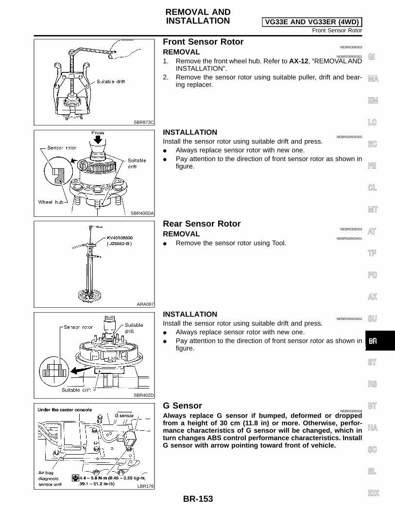
SBR873C
Front Sensor RotorNEBR0309S03
REMOVALNEBR0309S0301
1. Remove the front wheel hub. Refer to AX-12, “REMOVAL ANDINSTALLATION”.
2. Remove the sensor rotor using suitable puller, drift and bear-ing replacer.
SBR400DA
INSTALLATIONNEBR0309S0302
Install the sensor rotor using suitable drift and press. Always replace sensor rotor with new one. Pay attention to the direction of front sensor rotor as shown in
figure.
ARA097
Rear Sensor RotorNEBR0309S04
REMOVALNEBR0309S0401
Remove the sensor rotor using Tool.
SBR402D
INSTALLATIONNEBR0309S0402
Install the sensor rotor using suitable drift and press. Always replace sensor rotor with new one. Pay attention to the direction of front sensor rotor as shown in
figure.
LBR176
G SensorNEBR0309S06
Always replace G sensor if bumped, deformed or droppedfrom a height of 30 cm (11.8 in) or more. Otherwise, perfor-mance characteristics of G sensor will be changed, which inturn changes ABS control performance characteristics. InstallG sensor with arrow pointing toward front of vehicle.
REMOVAL ANDINSTALLATION VG33E AND VG33ER (4WD)
Front Sensor Rotor
BR-153
GI
MA
EM
LC
EC
FE
CL
MT
AT
TF
PD
AX
SU
ST
RS
BT
HA
SC
EL
IDX

ABS Actuator and Electric Unit=NEBR0309S07
LBR173
REMOVALNEBR0309S0701
1. Disconnect battery cable.2. Drain brake fluid. Refer to “Changing Brake Fluid”, BR-9.3. Remove mounting bracket fixing bolts and nuts.4. Disconnect connector, brake pipes and remove fixing nuts and
actuator ground cable.
INSTALLATIONNEBR0309S0702
CAUTION:After installation, refill brake fluid. Then bleed air. Refer to“Bleeding Brake System”, BR-11.1. Tighten actuator ground cable.Place ground cable at a notch of mounting bracket.2. Connect brake pipes temporarily.3. Tighten fixing bolts and nuts.4. Tighten brake pipes.5. Connect connector and battery cable.
REMOVAL ANDINSTALLATION VG33E AND VG33ER (4WD)
ABS Actuator and Electric Unit
BR-154

General SpecificationsNEBR0080
Unit: mm (in)
Applied model KA24DE VG33E and VG33ER
Front brake
Brake model CL28VD
Cylinder bore diameter × numberof pistons
42.8 (1.685) x 2
PadLength × width × thickness
146.6 x 48.5 x 10(5.77 x 1.909 x 0.39)
Rotor outer diameter × thickness 260 x 26 (10.2 x 1.02) 277 x 26 (10.9 x 1.02)
Rear brake
Brake model LT26B LT30A
Cylinder bore diameter 22.22 (7/8) 20.64 (13/16)
Lining length × width × thickness249.6 x 50 x 5.5 (9.83 x 1.97 x
0.217296 × 50 × 6.1
(11.65 × 1.97 × 0.240)
Drum inner diameter 260.0 (10.23) 295.0 (11.61)
Master cylinder Bore diameter 25.40 (1)
Control valve
Valve model Linkage type load sensing valve Proportioning valve within master cylinder
Split pointkPa (kg/cm2, psi) × reducing ratio
(Variable) x 0.23 2,452 (25,356) × 0.3
Brake booster
Booster model M195T M230t
Diaphragm diameterPri: 205 (8.07)Sec: 180 (7.09)
Pri: 230 (9.06)Sec: 230 (9.06)
Recommended brake fluid DOT 3
Disc BrakeNEBR0081
Unit: mm (in)
Brake model CL28VD
Pad wear limit Minimum thickness 2.0 (0.079)
Rotor repair limit Minimum thickness 24.0 (0.945)
Drum BrakeNEBR0082
Unit: mm (in)
Brake model LT26B LT30A
Lining wear limit Minimum thickness 1.5 (0.059)
Drum repair limitMaximum inner diameter 261.5 (10.30) 296.5 (11.67)
Out-of-round limit 0.03 (0.0012)
Brake PedalNEBR0083
Unit: mm (in)
Transmission M/T A/T
Free height “H”*191 - 201
(7.52 - 7.91)201 - 211
(7.91 - 8.31)
Depressed height “D”[under force of 490 N (50 kg, 110 lb) with engine running]
105 (4.13) 115 (4.53)
Clearance “C” between pedal stopper and threaded end of stop lamp switch or ASCD switch 0.3 - 1.0 (0.012 - 0.039)
Pedal free play At pedal pad 1.0 - 3.0 (0.039 - 0.118)
*: Measured from surface of metal floor to pedal pad
SERVICE DATA AND SPECIFICATIONS (SDS)General Specifications
BR-155
GI
MA
EM
LC
EC
FE
CL
MT
AT
TF
PD
AX
SU
ST
RS
BT
HA
SC
EL
IDX
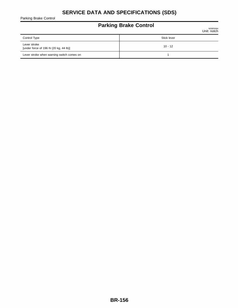
Parking Brake ControlNEBR0084
Unit: notch
Control Type Stick lever
Lever stroke[under force of 196 N (20 kg, 44 lb)]
10 - 12
Lever stroke when warning switch comes on 1
SERVICE DATA AND SPECIFICATIONS (SDS)Parking Brake Control
BR-156