real-time vibration analyzer owner’s...
TRANSCRIPT

“The System Solution”
Real-Time Vibration Analyzer
Owner’s Manual

VI-400PROPROPROPRO
Real-Time Vibration Analyzer
PRELIMINARY OWNER’S MANUAL
072-021
Rev. A
11/01/2005

CONTENTS _________________________________________________________________
1. INTRODUCTION 1 - 1 Main features of the VI-400PRO 1 - 1
2. MANUAL CONTROL OF THE INSTRUMENT 2 - 1
2.1. CONTROL PUSH-BUTTONS ON THE FRONT PANEL 2 - 1
2.2. INPUT AND OUTPUT SOCKETS OF THE INSTRUMENT 2 - 4
3. SETTING UP THE INSTRUMENT 3 - 1
3.1. BASIS OF THE INSTRUMENT’S CONTROL 3 - 1
3.2. POWERING THE INSTRUMENT 3 - 19
3.2. INITIAL SETUP OF THE INSTRUMENT 3 - 20
4. MEASUREMENT FUNCTIONS OF THE INSTRUMENT 4 - 1
4.1. CALIBRATION 4 - 3
4.1.1. The calibration by the sensitivity introduction 4 - 4 Calibration BY SENSITIVITY in the case of vibration signal 4 - 4 Calibration BY SENSITIVITY in the case of acoustic signal 4 - 5
4.1.2. The calibration by the measurement 4 - 6 Calibration BY MEASUREMENT in the case of vibration signal 4 - 6 Calibration BY MEASUREMENT in the case of acoustic signal 4 - 7
4.2. LEVEL METER 4 - 9
4.2.1. Sound level meter 4 - 10 One profile mode of measurement results presentation 4 - 12 3 PROFILES mode of measurement results presentation 4 - 13 Presentation of the statistical analysis results - STATISTICS 4 - 13 Presentation of time history - PLOT 4 - 14
4.2.2. Vibration level meter 4 - 16 One profile mode of measurement results presentation 4 - 17 3 PROFILES mode of the measurement results presentation 4 - 18 Presentation of time history - PLOT 4 - 18
4.2.3. Measurement parameters setting 4 - 21
Measurement parameters setting - INPUT list 4 - 21
Selection of measurement parameters - MEASURE SETUP 4 - 22 Setting time delay before the start of measurements - START DELAY 4 - 22 Setting the integration time - INT. TIME 4 - 23 Setting number of repetition of measurement cycles - REP. CYCLE 4 - 24 Setting time between two writings to the buffer’s file - BUF. STEP 4 - 24
Setting parameters in channels and for octave analysis - CHANNELS SETUP 4 - 24 Setting parameters in a channel – CHANNEL x 4 - 25
Selection of the instruments mode - MODE 4 - 25 Selection of the measurement range - RANGE 4 - 25

Selection of the microphone correction – MIC. Correction 4 - 26 Selection of the channel profiles – PROFILE x 4 - 27 Selection of the weighting filter and RMS detection in SLM - FILTER 4 - 27 Selection of the weighting filter in VLM - FILTER 4 - 28 Selection of the RMS detector in VLM - DETECTOR 4 - 29
Selection of the measurement parameters - BUFFERS SETUP 4 - 30 Selection of the result to be saved in the buffer’s file - BUFFERS 4 - 30
Selection of mode and triggering parameters - TRIGGER SETUP 4 - 32 Switching the triggering on and off - TRIGGER 4 - 32 Selection of the triggering signal in SLM - SOURCE 4 - 34 Setting the level of triggering - LEVEL 4 - 34 Setting the parameter related with the buffer triggering - PRE/POST TRIGGER 4 - 34
4.3. ACTIVATION OF OPTIONAL FUNCTIONS 4 - 38
4.4. 1/1 OCTAVE ANALYZER 4 - 39
4.4.1. 1/1 OCTAVE analyzer of acoustic signal 4 - 40
Selection of the measurement range in 1/1 OCTAVE analysis of acoustic 4 - 43 signal - RANGE
Selection of 1/1 OCTAVE analysis result of acoustic signal to be saved 4 - 45 in the buffer’s file –BUFFERS SETUP
Selection of 1/1 OCTAVE analysis parameters for acoustic signal - SPECTRUM 4 - 46 Selection of the weighting filter in 1/1 OCTAVE analysis of acoustic signal - FILTER 4 - 46 Selection of 1/1 OCTAVE analysis result to be saved in the buffer’s file – BUFFER 4 - 47 Selection of the result which triggers registration in BUFFER mode in 1/1 4 - 47 OCTAVE analysis of acoustic signal
4.4.2. 1/1 OCTAVE analyzer of vibration signal 4 - 49
Measurement range selection in 1/1 OCTAVE analysis of vibration signal - RANGE 4 - 53
Selection of 1/1 OCTAVE analysis result of vibration signal to be saved in the buffer’s 4 - 54 file – BUFFERS SETUP
Selection of 1/1 OCTAVE analysis parameters for vibration signal - SPECTRUM 4 - 55 Selection of 1/1 OCTAVE analysis result of vibration signal to be saved in the 4 - 56 buffer’s file - BUFFER Selection of the result which triggers registration in BUFFER mode in 1/1 OCTAVE 4 - 56 analysis of vibration signal
4.5. 1/3 OCTAVE ANALYZER 4 - 58
4.5.1. 1/3 OCTAVE analyzer of acoustic signal 4 - 59
Selection of the measurement range selection in 1/3 OCTAVE analysis of acoustic 4 - 62 signal - RANGE
Selection of 1/3 OCTAVE analysis result of acoustic signal to be saved in the buffer’s
file – BUFFERS SETUP 4 - 63
Selection of 1/3 OCTAVE analysis parameters for acoustic signal - SPECTRUM 4 - 65 Selection of the weighting filter in 1/3 OCTAVE analysis of acoustic signal – FILTER 4 - 65 position Selection of 1/3 OCTAVE analysis result to be saved in the buffer’s file – BUFFER position 4 - 66 Selection of the result which triggers registration in BUFFER mode in 1/3 OCTAVE analysis of acoustic signal 4 - 67

4.5.2. 1/3 OCTAVE analyzer of vibration signal 4 - 68
Measurement range selection in 1/3 OCTAVE analysis of vibration signal - RANGE 4 - 75
Selection of 1/3 OCTAVE analysis result of vibration signal to be saved in the buffer’s 4 - 76 file – BUFFERS SETUP
Selection of 1/3 OCTAVE analysis parameters for vibration signal - SPECTRUM 4 - 77 Selection of 1/3 OCTAVE analysis result of vibration signal to be saved in the buffer’s 4 - 78 file - BUFFER Selection of the result which triggers registration in BUFFER mode in 1/3 OCTAVE 4 - 78 analysis of vibration signal
4.6. DOSE ANALYZER (FOR FUTURE USE)
5. AUXILIARY FUNCTIONS 5 - 1
5.1. DATA AVAILABLE ON THE SCREEN - DISPLAY LIST 5 - 1
Selection of the modes of measurement results presentation - DISPLAY MODES 5 - 1
Selection of the parameters in graphical results presentation - DISPLAY SETUP 5 - 3 Setting of the scale in graphical results presentation – DISPLAY SCALE 5 - 4 Scaling of the vertical axis of the graphical presentation - DYNAMIC 5 - 4 Scaling of the horizontal axis of the graphical presentation - X-ZOOM 5 - 4
Selection of the weighted filters – TOTAL VALUES 5 - 5 Selection of the weighted filters for the 1st profile – TOTAL 1 5 - 5 Selection of the weighted filters for the 2nd profile – TOTAL 2 5 - 6 Selection of the weighted filters for the 3rd profile – TOTAL 3 5 - 6
Selection of spectrum type - SPECTRUM TYPE 5 - 7
Selection of the buffer’s file to the display presentation – BUFFER VIEW 5 - 8
Checking the state of the internal battery - BATTERY 5 - 12
Setting the contrast of the display - CONTRAST 5 - 13
Setting the backlight parameters - BACKLIGHT 5 - 14 Automatic switch off of the backlight - TIMEOUT 5 - 14 Setting the brightness of the backlight - BRIGHTNESS 5 - 14
Checking specification of the instrument - UNIT LABEL 5 - 15
5.2. SETUP MENU 5 - 16
Programming of the instrument’s internal timer - TIMER 5 - 17
Programming of the instrument’s internal Real Time Clock - RTC 5 - 18
Setting the conditions for the diffuse field measurements - FIELD CORRECTION 5 - 18
Introduction the filter coefficients for 1/3 (1/1) OCTAVE analysis - USER FILTERS 5 - 19 Setting the coefficients of the user filters set – EDIT (position) 5 - 21 Setting the coefficients of the user filters– CLEAR 5 - 21
Selection of statistics levels to be saved in a file – STAT. LEVELS 5 - 22
Selection of the external mode – EXT. I/O SETUP 5 - 23
Selection of few push-buttons mode - SHIFT MODE 5 - 24 Selection of the working mode of <Altf> push-button - SHIFT 5 - 24 Selection of the working mode of <START / STOP> push-button - ST/SP 5 - 24

Return to the factory made settings - CLEAR SETUP 5 - 25
Selection of detector’s type in the LEQ (RMS) calculations - RMS INTEGRATION 5 - 26
Setting the reference signal in vibration measurements - REFERENCE LEVEL 5 - 27 Setting the reference level of the acceleration signal - ACC 5 - 27 Setting the reference level of the velocity signal - VEL 5 - 27 Setting the reference level of the displacement signal - DIL 5 - 28
Selection of the vibration units - VIBRATION UNITS 5 - 28
Selection of the warnings - WARNINGS 5 - 29 Saving the measurement results in a file - RES.NOT SAVE 5 - 29
Selection of the vector coefficient – VECTOR DEF. 5 - 30
Selection of the vibration dose – HAV/WBV DOSE 5 - 31 Selection of the parameters of vibration dose – MEASURE DOSE 5 - 32 Selection of the parameters of vibration dose – EXPOSURE TIME 5 - 32 Selection of the parameters of vibration dose – AXIS SETUP 5 - 33 Selection of the standard of vibration dose – STANDARDS 5 - 34
5.3. SAVING THE MEASUREMENT RESULTS 5 - 36
Saving files 5 - 36
Selection of the file’s operation - FILE 5 - 37
Saving files in the instrument’s memory - SAVE and SAVE NEXT 5 - 38
Controlling the data storing in the instrument’s memory - SAVE OPTIONS 5 - 41 Saving of the filters to the RAM memory – RAM FILE 5 - 41 Replacement of the existing files by the new ones - REPLACE 5 - 41 Controlling of the measurement statistics savings - SAVE STAT. 5 - 42 Controlling of the measurement results savings - AUTO SAVE 5 - 42
Loading the files with the measurement results - LOAD 5 - 43
Removing a file with the measurement results from memory - DELETE 5 - 45
Removing all files with measurement results from memory - DELETE ALL 5 - 46
Memory merging - DEFRAGMENTATION 5 - 47
Removing all files with results from buffer’s memory - CLEAR BUFFER 5 - 48
Checking the contents of the memory - CATALOGUE 5 - 49
Checking the free space in the memory - FREE SPACE 5 - 50
Saving setup in the instrument’s memory - SAVE SETUP and SAVE NEXT SETUP 5 - 51
Loading the files with the configuration – LOAD SETUP 5 - 53
Operations in buffer 5 - 56
5.4. CALCULATION OF THE DOSE PARAMETERS – AUX. FUNCTIONS 5 - 58
Selection of the calculation results – HAV CALCULATOR 5 - 58 Selection of the file with results of measurement – RESULT SEL. 5 - 59 Selection of the partial results – PARTIAL EAV/ELV 5 - 61 Selection of the partial exposure – PARTIAL EXP. 5 - 61 Selection of the daily exposure – DAILY EXPOSURE 5 - 62
Selection of the calculation results – WBV CALCULATOR 5 - 62 Selection of the file with results of measurement – RESULT SEL. 5 - 63

Selection of the partial results – PARTIAL EAV/ELV 5 - 64 Selection of the partial exposure – PARTIAL RESULTS 5 - 65 Selection of the daily exposure – DAILY RESULTS 5 - 66
APPENDIX A. (For Future Use) A - 1
APPENDIX B. (For Future Use) B - 1
APPENDIX C. DATA SPECIFICATION C - 1
C.1. SPECIFICATION OF VI-400Pro AS SOUND LEVEL METER C - 1
C.2. SPECIFICATION OF VI-400Pro AS 1/1 OCTAVE, 1/3 OCTAVE AND FFT C - 8
SOUND ANALYZER
C.3. SPECIFICATION OF VI-400Pro AS VIBRATION LEVEL METER / ANALYZER C - 12
C.3. MISCELLANEOUS SPECIFICATION OF VI-400Pro C - 16
APPENDIX D. DEFINITIONS AND FILTER CHARACTERISTICS D - 1
D.1. DEFINITIONS AND FORMULAE D - 1
D.1.1. Definitions of the results available in the SLM mode of the VI-400Pro D - 1
D.1.2. Definitions of the Hand-Arm vibration results available in the vibration mode of the D - 2
VI-400 Pro
D.1.3 Definitions of the Whole-Body vibration results available in the vibration mode of the D - 3
VI-400Pro
D.1.4. Definitions of the results available in the sound mode of the VI-400Pro D - 5
D.2. CHARACTERISTICS OF DIGITAL FILTERS IMPLEMENTED IN VI-400Pro D - 8

VI-400PRO USER MANUAL
1 - 1
1. INTRODUCTION
The VI-400PRO is an all digital, four channel, Type 1 vibration meter and analyzer, with optional Class 1 sound analysis. It is an ideal choice for machine, hand-arm or whole body vibration measurement using channels 1, 2 and 3 with appropriate accelerometer/s and sound measurement using channel 4 with a microphone and preamp.
Large 32 MB internal memory of the VI-400PRO can store time history for all channels over the whole working day. Measurement results are easily downloaded to any PC using the USB 1.1 interface and QuestSuite® Professional II software. QuestSuite® Professional II software can also be used to store user setup profiles and program them into the VI-400PRO.
The VI-400PRO, using the computational power of its built-in digital signal processor, can perform real-time 1/1 or 1/3 octave and (optional) real-time FFT analysis.
Robust, lightweight construction allow the VI-400PRO to be used in harsh environmental conditions.
The main features of VI-400PRO instrument are as follows:
General features of VI-400PRO
• Internal buffer for logging more then two weeks of 1 sec RMS / MAX / MIN / PEAK results - in the SLM mode and RMS / MAX / P–P / PEAK results - in the VLM mode (32 MB of non-volatile memory).
• USB 1.1 interface .
• Operates from four user replaceable “AA” size alkaline batteries (operational time > 8 h).
• Handheld, robust case
• Light weight ( 500 grams)
VI-400PRO as Vibration Meter & Analyzer
• Vibration measurements according to ISO 2631-1 with Type 1 accuracy (ISO 8041) in the frequency range 1 Hz ÷ 20 kHz.
• Simultaneous PEAK, RMS (incl. MTVV) and RMQ (incl. VDV) measurements.
• W–Bxy, W–Bz, W-Bc, KB, H–A, Wk, Wc, Wd, Wj (ISO 8041 and ISO 2631-1) weighting filters
• 1/1 octave and 1/3 octave real time analysis - 15 filters with center frequencies 1 Hz ÷ 16 kHz, Type 1 - IEC 1260 and 45 filters with center frequencies 0.8 Hz ÷ 20 kHz, Type 1 - IEC 1260.
• FFT calculation (optional) (1920 lines in real time up to 22.4 kHz with Hanning – kl window and linear averaging) spectra simultaneous to the VLM operation.
VI-400PRO as Sound Level Meter & Analyzer
• Noise measurements (SPL, LEQ, SEL, Lden, Ltm3, Ltm5 and statistics) with Type 1 accuracy in the frequency range of 10 Hz to 20 kHz.
• Simultaneous IMPULSE, FAST and SLOW detectors for the sound measurements with A, C or LIN filters.
• 1/1 octave and 1/3 octave real time analysis (optional) - 15 filters with center frequencies 1 Hz to 16 kHz, Type 1 - IEC 1260 and 45 filters with center frequencies 0.8 Hz to 20 kHz, Type 1 - IEC 1260.
• FFT calculation(optional) (1920 lines in real time up to 22.4 kHz with Hanning window and linear averaging) spectra parallel to the SLM operation.

VI-400PRO USER MANUAL .
1 - 2
Analyzer Kits
• VI-400Pro Real-Time Vibration Analyzer Less Sensors - Includes VI-400Pro Analyzer w/USB Computer Interface cable and 072-008 Storage case.
• VI-400Pro Real-Time Hand-Arm Vibration Analyzer Kit - Includes VI-400Pro Real-Time Vibration Analyzer w/USB Computer Interface cable, 072-010 Tri-axial HAV sensor, 072-022 Sensor Cable, 072-005 HAV Sensor Mounting Block and Clamp Assembly and 072-008 Storage case.
• VI-400Pro Real-Time Whole-Body Vibration Analyzer Kit - Includes VI-400Pro Real-Time Vibration Analyzer w/USB Computer Interface cable, 072-011 Tri-Axial WBV Seat-Pad Sensor, 072-022 Sensor Cable and 072-008 Storage Case.
• VI-400Pro Real-Time Hand-Arm & Whole-Body Vibration Analyzer kit – Includes VI-400Pro Real-Time Vibration Analyzer, 072-010 Tri-axial HAV sensor, 072-005 HAV Sensor Mounting Block and Clamp Assembly, 072-011 Tri-Axial WBV Seat-Pad Sensor, 072-022 Sensor Cable and 072-008 Storage Case.
Optional Accessories
• QSP-PROII , QuestSuite Pro II Single-User License
• QSP-PROII-10, QuestSuite Pro II Ten-User License
• QSP-PROII-UNL, QuestSuite Pro II Unlimited-User License
• 072-018 , Handheld Vibration Calibrator/Shaker
• 072-026, Sub-Miniature Tri-Axial HAV Sensor – Measures 9.14 x 9.14 x 12.19 mm (0.36 x 0.36 x 0.48 in)
• 072-029, VI-400Pro Tri-Axial WBV Sensor with cable
• 072-028, Microphone Pre-Amplifer – For connecting 59-523 microphone to 4th input channel of VI-400Pro. Microphone purchased separately.
• 072-032, T-Handle Adapter for Hand-Arm Vibration Measurements
• 59-523, B&K 4936 ½” Class 1 Pre-Polarized Microphone – Pre-amplifer and microphone purchased separately.
• 56-990, Microphone to Calibrator Adapter – For ½” diameter microphone to “QC” series Acoustical Calibrator.
• QC-20, Acoustical calibrator - w/ Selectable Output 114 dB or 94 dB at 1000 Hz or 250 Hz. Microphone to Calibrator adapter purchased separately.

VI-400PRO USER MANUAL
2 - 1
2. MANUAL CONTROL OF THE INSTRUMENT
The keyboard of the VI-400Pro contains 9 keys. Using these 9 keys individually or in tandem with one another the user has full access to all setup and data display functions. The display of the VI-400Pro presents informatation in a series of menus form which a selection can be made. Although all functions can be performed on board the VI-400Pro via the keypad, use of the optional Quest Suite Professonial II software significantly simplifies all tasks of setting up the unit, retrieving, reviewing and presentation of data.
2.1. CONTROL PUSH-BUTTONS ON THE FRONT PANEL
The front panel of the VI-400Pro instrument contains the following control push-buttons:
1. <Enter>, (<Menu>).
2. <Esc> escape, (< >) backlight.
3. <Alt f> alternate function.
4. < > up arrow.
5. < > left arrow.
6. < > right arrow.
7. < > down arrow.
8. <Pause>, (<Proceed>).
9. <Start / Stop>.
The name in brackets (...) denotes the alternate function of a push-button which is available using the <Alt f> push-button.
The view of the control push-buttons of the VI-400PRO instrument

VI-400PRO USER MANUAL .
2 - 2
<Alt f> The <Alt f> push-button can be programmed by the user to function in “Shift” mode or “2nd Function”
mode. • In “Shift” mode an alternate function is accessed by pressing the <Alt f> push-button and the
desired push-button at the same time. • In “2nd Function” mode and alternate function is accessed by first pressing and releasing the
<Alt f> push-button then pressing the desired push-button.
Notice: The operation of the <Alt f> push-button can be set as the “Shift” mode or the “2nd Fun.” mode in the SHIFT MODE window of the SETUP list (see Chapter 5 for the SETUP list description). ___________________________________________________________________________________
<START / STOP> This push-button enables one to start or stop the measurement process. It can be programmed by
the user to function in “Normal” or “Inverse” modes. • In “Normal” mode, pressing just the <START / STOP> push-button once, will start or stop the
measurement process. • In “Inverse” mode, pressing <Alt f> in conjunction with the <START / STOP> push-button, will
start or stop the measurement process.
Notice: The operation of the <START / STOP> push-button mode can be set as “Normal” or “Inverse” in the SHIFT MODE window of the SETUP list (see Chapter 5 for the SETUP list description).
Notice: The “Shift” or “2nd Fun.” operation mode of the <Alt f> push-button is independent of the “Normal” or “Inverse” mode setting of the <START / STOP> push-button. ___________________________________________________________________________________
<PAUSE> This push-button enables one to temporarily cease the measurement process. The last one
second measurement result is deleted after the subsequent pressing of the <PAUSE> push-button. Up to fifteen last seconds of the measurement can be cancelled in this way. ___________________________________________________________________________________
(<PROCEED>) This push-button, pressed in conjunction with the <Alt f>, enables the user to continue the
measurement process that was ceased temporarily by pressing the <PAUSE> push-button.
Notice: The simultaneous pressing of the <PAUSE> and <START / STOP> push-buttons switches the instrument on and off. ___________________________________________________________________________________
<ENTER> This push-button enables one to enter the selected operation mode or to confirm control options.
Some additional functions of this push-button will be described in the following chapters. ___________________________________________________________________________________
(<MENU>) This push-button, pressed in conjunction with <Alt f>, enables the user to enter the main list
containing six sub-lists: FUNCTION, INPUT, DISPLAY, FILE, AUX. FUNCTIONS and SETUP. Each of the mentioned above sub-lists consists of the sub-lists, elements and data windows. These main sub-

VI-400PRO USER MANUAL
2 - 3
lists will be described in detail in the following chapters of the manual. Double pressing the <MENU> push-button enters a list containing the four last opened sub-lists. This often speeds up the control of the instrument. ___________________________________________________________________________________
<ESC> This push-button closes the control lists, sub-lists or windows. It acts in opposite to the <ENTER>
push-button. When a window is closed by pressing the <ESC> push-button, in almost all cases, any changes made will be ignored. ___________________________________________________________________________________
(< >) This push-button, pressed in conjunction with <Alt f>, enables the user to switch on or off the
backlight of the display screen. ___________________________________________________________________________________
< >, < > These push-buttons navigate left or right and enable the user to:
• select the options in an active position in the "horizontal direction" (e.g. filter: LIN, A or C, Integration time: 1s, 2s, 3s, … etc.),
• select the measurement result to be displayed (e.g. PEAK, MAX, MIN, etc.) in One Profile and 3 PROFILES modes of result’s presentation),
• control the cursor in SPECTRUM, PLOT and STATISTICS modes of result’s presentation,
• select the position of the character in the text edition (i.e. in the FILE NAME menu). ___________________________________________________________________________________
(< >, < >) These push-buttons, pressed in conjunction with <Alt f>, enable the user to:
• speed up the changing of the numerical values of the parameters (i.e. the step is increased from 1 to 10 in the setting of START DELAY).
• insert or delete a character in the text edition modes,
• change the statistics class (the number displayed after the letter L) in One Profile and 3 PROFILES modes of result’s presentation,
Some other possible reactions of the instrument to the pressing of these push-buttons will be described in details in the following chapters. ___________________________________________________________________________________
< >, < > These push-buttons navigate up or down and enable the user to:
• change the mode of result’s presentation,
• select the proper character from the list in the text edition mode,
• switch the active sub-list in a list.
• programme the Real Time Clock (RTC) and TIMER. Some other possible reactions of the instrument to the pressing of these push-buttons will be
described in details in the following chapters. ___________________________________________________________________________________
(< >, < >) These push-buttons, pressed in conjunction with the <Alt f>, enable the user to:
• change the relation between the Y-axis and X-axis of all plots presented on the screen, • switch the channels and profiles in One Profile and STATISTICS modes of result’s presentation, • switch the active channel in 3 PROFILES mode of result’s presentation
Some other possible reactions of the instrument to the pressing of these push-buttons will be described in details in the following chapters.

VI-400PRO USER MANUAL .
2 - 4
2.2. INPUT AND OUTPUT SOCKETS OF THE INSTRUMENT
The measurement inputs, called Channels, are placed on the top cover of the instrument. There is
a 4-pin Lemo socket for Channels 1-3 and a TNC connector for Channel 4, all with IEPE power supply for the accelerometers or microphone preamplifiers. The microphone preamplifier 072-028 has the proper plug-in with the screw for connection directly to Channel 4 of the instrument but it is recommended to use the preamplifier with any extension cable. The vibration accelerometer is attached to the VI-400Pro directly or using an appropriate cable depending on the particular accelerometer being used.
Notice: The TNC connector is a screw on type and should be tightened to a snug fit while the Lemo connector is push-pull only.
The full description of the signals connected to the sockets is given in the Appendix C.
Lemo- channels 1, 2 and 3 TNC – channel 4
The view of the top cover of the VI-400PRO instrument in 1:1 scale
In the bottom cover are three connections for: USB (in the middle of the figure below), AC / Int. (on the left side of the figure below) and Ext. Power (on the right side of the figure below).
The view of the bottom cover of the VI-400PRO instrument in 1:1 scale
The USB 1.1 interface is the serial interface working with 12 MHz clock. The standard 4-pin socket used is described in detail in Appendix C.

VI-400PRO USER MANUAL
2 - 5
The additional input / output socket, AC / Int.(the left one in the Fig. above), is a 1-pin LEMO, compatible socket type ERN.00.250. The function of this AC / Int. socket can be selected from menu (path: MENU / SETUP / EXT. I/O SETUP / MODE). The socket can be used as:
• analog output with the signal from the input of the analog / digital converter (before correction); this signal can be registered using magnetic recorder or observed on the oscilloscope (the ANALOG setting)
• digital input for external interrupt (the DIGITAL IN setting)
• digital output for external trigger (the DIGITAL OUT setting)
The Ext. Power socket (the right one in the Fig. above), located on the bottom cover of the instrument is a Marushin MJ-14 compatible socket, dedicated for the standard 5.5 / 2.1 mm plug. The user can connect the external AC adapter (110 V / 230 V) which furnishes the proper DC level. The instrument can be charged from the external DC source (from 6 V to 24 V).
Notice: Switch the power off before connecting the instrument to any other device (e.g. a printer or a Personal Computer).
The view of the front panel of the VI-400PRO instrument

VI-400PRO USER MANUAL .
2 - 6
The view of the rear panel of the VI-400PRO instrument

VI-400PRO USER MANUAL
3 - 1
3. SETTING UP THE INSTRUMENT
In order to perform measurements using the instrument the user has only to plug in the preamplifier with the microphone and/or the appropriate vibration accelerometer then switch the power on.
3.1. BASIS OF THE INSTRUMENT’S CONTROL
The instrument is controlled by means of nine push-buttons of the keyboard. Using these push-buttons one can access all available functions. The functions are placed in the system of lists and sub-lists. The main list contains the headers of six lists which also contain sub-lists or positions (elements). The main list is opened after pressing the <MENU> push-button. This list contains the following lists: FUNCTION, INPUT, DISPLAY, FILE, AUX. FUNCTIONS and SETUP. The elements of each list are described in details in Chapter 4 and 5. Only the one highlighted item can be accessed at a time. Pressing the <5555>, <6666> (or <3333>, <4444>) push-buttons will change the highlighted line.
The view of the displays with the highlighted elements of the main list Double pressing of the <MENU> push-button displays a list containing the four sub-lists most
recently accessed by the user. The example of this list is presented below. This functionality enables one to quickly access the four most frequently used lists.
The view of the display (after double pressing of the <MENU> push-button) with the sub-lists which were most recently accessed by the user.
After the selection of the desired list using the <5555> or <6666> push-buttons, the user has to press
the <ENTER> push-button to enter the choice. After this a new sub-list, position (element) or various data specification will appear on the display.

VI-400PRO USER MANUAL
3 - 2
a) b)
The view of the displays with the main list (a) and the elements of the INPUT list (b)
Next pressing of the <ENTER> push-button enables one to access mentioned above sub-lists.
The view of the display with the opened MEASURE SETUP sub-list (path: MENU / INPUT / MEASURE SETUP)
The desired position of a list is accessed after pressing the <5555> or <6666> push-button.
The display with the opened MEASURE SETUP sub-list; the INT.TIME position accessible
To change the value in a selected position, press the <3333> or <4444> push-buttons.
The displays with the accessed INT.TIME position after pressing the <3333> or <4444> push-buttons, respectively The <ENTER> push-button is used to confirm the selection in a position and for closing the opened
sub-list. The sub-list can be closed ignoring any changes made in that sub-list by pressing the <ESC> push-button.
The displays viewed after pressing the <ESC> push-button three consecutive times from the MEASURE SETUP sub-list
Some of the sub-lists end with the window informing the user about the state of the instrument, available memory, non-existing files or buffers, standards fulfilled by the unit, etc.

VI-400PRO USER MANUAL
3 - 3
The view of the displays during and after the accessing the FREE SPACE window (path: MENU / FILE)
In order to close such window the user has to press the <ESC> push-button.
In the instrument there are also windows which are used for entering text (i.e. the name of the file).
The displays during the edition of the text which will be the name of the file as saved in instruments memory
Below the structure of the elements of the main list is presented. The more detailed description of the FUNCTION and INPUT lists is given in Chapter 4 and the DISPLAY, FILE, AUX. FUNCTIONS and SETUP lists – in Chapter 5.
FUNCTION (one of the main lists available after pressing the <MENU> push-button)
MEASUREMENT FUNCTION (sub-list) LEVEL METER (position); available values: [ ] / [*] 1/1 OCTAVE (position); available values: [ ] / [*] 1/3 OCTAVE (position); available values: [ ] / [*] FFT (position); available values: [ ] / [*]
Note: The * indicates which of the meter functions has been selected. Only one selected measurement function is available at any given time.
CALIBRATION (sub-list) CHANNEL x
• BY SENSITIVITY (sub-list) o SENSIYIVITY (position); available values of the calibration level:
10 µV / ms-2 .. 10 V / ms-2 (for vibration measurements) and 50 µV / Pa .. 50 V / Pa (for sound measurements)
o CAL. FACTOR (position); it displays the calculated calibration factor • BY MEASUREMENT (sub-list)
o CAL. LEVEL (position); available values of the calibration level: 100 mm / s2 .. 1 km / s2 for vibration measurements (or 100 dB .. 180 dB if
the reference level was set to 1 µm / s2 and the LOG (logarithmic) scale was selected in the DISPLAY SCALE sub-list)
54dB .. 134dB for sound measurements o CAL. FACTOR (position); it displays the calculated calibration factor after the
measurement.

VI-400PRO USER MANUAL
3 - 4
Control diagram of the FUNCTION list
INPUT (from main list)
MEASURE SETUP (sub-list)
START DELAY (position); the time delay before measurements begin being collected, available values: 1s .. 60s
INT. TIME (position); integration time, available values: 1s .. 24h
REP. CYCLE (position); the number of measurement cycles which have to be repeated, available values: Inf, 1 .. 1000
BUF. STEP (position); the step, or amount of time, which the measurement results are saved in an instrument’s buffer, available values: 2ms .. 1h
CHANNELS SETUP (sub-list)
CHANNEL x (sub-list)
• MODE (x) (position); available mode used in the channel during the measurements: o VIBR. - for vibration measurements and o SOUND - for sound measurements
• RANGE (position); available range measurements, the user can select the range: o 17.8m/s2 or 316m/s2 for vibration measurements and o 105dB or 130dB for sound analysis
• FILTER (position); available digital weighting filter used in the channel during the measurements o HP1, HP3, HP10, Vel1, Vel3, Vel10, VelMF, Dil1, Dil3, Dil10, W–Bxy, W–Bz, H–A,
W–Bc, KB, Wk, Wd, Wc, Wj - for vibration measurements and o LIN, A, C – for sound measurements
• DETECT. (position); available detector time constant used in the channel: o 100ms, 125ms, 200ms, 500ms, 1.0s, 2.0s, 5.0s, 10.0s - for vibration measurements
and o IMP., FAST, SLOW - for sound measurements
BUFFERS SETUP: (sub-list) available channel measurement results which will be saved in the instrument’s buffer:

VI-400PRO USER MANUAL
3 - 5
o None, PEAK, P–P, MAX, RMS - for vibration measurements and o None, PEAK, MAX, MIN, RMS - for sound measurements o VECTOR: available value of VECTOR which will be saved in the instrument’s buffer
1/1 OCTAVE SETUP or 1/3 OCTAVE SETUP (sub-list)
CHANNEL x: o SPECTRUM (sub-list); this sub-list is not available for Sound Level Measurement
(SLM) or Vibration Level Measurement (VLM) choices; it appears only for 1/1 OCTAVE or 1/3 OCTAVE analyzer choices.
• FILTER (position); available digital weighting filter used during 1/1 OCTAVE or 1/3 OCTAVE analysis, for sound measurements: HP, LIN, A, C
• BUFFER (position); available types of measurement results which will be saved in the instrument’s buffer during 1/1 OCTAVE or 1/3 OCTAVE analysis: o None, RMS - for vibration measurements o None, RMS, LEQ - for sound measurements
TRIGGER SETUP (sub-list)
TRIGGER (position); available values: Off, SLOPE +, SLOPE -, LEVEL +, LEVEL -, BUFFER
SOURCE: (position); the source of the triggering signal:
SOURCE: (position); the source of the triggering signal: o VECT, RMS, 125Hz, 250Hz, 500Hz, ..., 16kHz - for vibration measurements with
BUFFER selected in the TRIGGER position and 1/1 OCTAVE function; VECTRMS, 125Hz, 160Hz, 200Hz, ..., 20kHz - for vibration measurements with BUFFER selected in the TRIGGER position and 1/3 OCTAVE function; VECTRMS - for vibration measurements and VLM or FFT function.
o VEC/SND, MAX, 125Hz, 250Hz, 500Hz, ..., 16kHz - for sound measurements with BUFFER selected in the TRIGGER position and 1/1 OCTAVE function; VEC/SNDMAX, 125Hz, 160Hz, 200Hz, ..., 20kHz - for sound measurements with BUFFER selected in the TRIGGER position and 1/3 OCTAVE function LEVEL (position); available values of the triggering level
o 1.00mm/s2 .. 10.0km/s2 - for vibration measurements (or 60dB .. 200dB if the reference level was set to 1 µm/s2 and the LOG (logarithmic) scale was selected in the DISPLAY SCALE sub-list)
o 24dB .. 136dB - for sound measurements
PRE/POST TRIGGER (sub-list); number of the records saved before (PRE) and after (POST) the triggering actually occurs
• PRE (position); available number of records: 0 .. 50
• POST (position); available number of records: 0 .. 200

VI-400PRO USER MANUAL
3 - 6
Control diagram of the INPUT menus

VI-400PRO USER MANUAL
3 - 7
DISPLAY (from main menu)
DISPLAY MODES (sub-list); allows the user to activate ([√√√√]) or switch off ([ ]) the available modes of presenting results
SPECTRUM (position); available choices: [√√√√] or [ ]; this position is not active in the SLM or VLM mode
3 PROFILES (position); available choices: [√√√√] or [ ]
STATISTICS: (position); available choices: [√√√√] or [ ]
PLOT: (position); available choices: [√√√√] or [ ]
DISPLAY SETUP (sub-list) CHANNEL x
• DISPLAY SCALE: (sub-list) o SCALE: (position); available values for the scale of graphical modes of
presenting results: LIN (linear), LOG (logarithmic) - for vibration measurements and LOG (logarithmic) - for sound measurements
o DYNAMIC: (position); available values for the dynamics of graphical modes of presenting results: 80dB, 40dB, 20dB, 10dB
o X-ZOOM: (position); the multiplier for the horizontal axis for the graphical modes of presenting results: 1x
• TOTAL VALUES o TOTAL 1: (sub-list) the weighted filter to be used for the calculation of the
TOTAL value in the first profile FILTER: (position); available values of the weighted filters:
• for sound measurements: A, SUSR1, SUSR2, SUSR3 or any other sent to the unit via the interface
• for vibration measurements: HP, VUSR1, VUSR2, VUSR3 or any other sent to the unit via the interface
TYPE: (position available only for vibration measurements); available values if VUSR1, VUSR2 or VUSR3 was selected in the FILTER position: ACC, VEL and DIL; if the HP filter was selected this position is not displayed
CAL. F.: (position available only for vibration measurements); accessible if VUSR1, VUSR2 or VUSR3 was selected in the FILTER position; if the HP filter was selected in the 1st channel this position is not displayed; available values from -60.0dB to 60.0dB with 0.1dB or 1 dB step
o TOTAL 2: (sub-list) the weighted filter to be used for the calculation of the
TOTAL value in the second profile FILTER: (position); available values of the weighted filters:
• for sound measurements: C, SUSR1, SUSR2, SUSR3 or any other sent to the unit via the interface
• for vibration measurements: CH, VUSR1, VUSR2, VUSR3 or any other sent to the unit via the interface
TYPE: (position available only for vibration measurements); available values if VUSR1, VUSR2 or VUSR3 was selected in the FILTER position: ACC, VEL and DIL; if the CH filter was selected in the 2nd channel this position is not displayed
CAL. F.: (position available only for vibration measurements); accessible if VUSR1, VUSR2 or VUSR3 was selected in the FILTER position; if the CH filter was selected in the 2nd channel this position is not displayed; available values from -60.0dB to 60.0dB with 0.1dB or 1 dB step
o TOTAL 3: (sub-list) the weighted filter to be used for the calculation of the
TOTAL value in the third profile:

VI-400PRO USER MANUAL
3 - 8
FILTER: (position); available values of the weighted filters:
• for sound measurements: LIN, SUSR1, SUSR2, SUSR3 or any other sent to the unit via the interface
• for vibration measurements: CH, VUSR1, VUSR2, VUSR3 or any other sent to the unit via the interface
TYPE: (position available only for vibration measurements); available values if VUSR1, VUSR2 or VUSR3 was selected in the FILTER position: ACC, VEL and DIL; if the CH filter was selected in the 3rd channel this position is not displayed
CAL. F.: (position available only for vibration measurements); accessible if VUSR1, VUSR2 or VUSR3 was selected in the FILTER position; if the CH filter was selected in the 3rd channel this position is not displayed; available values from -60.0dB to 60.0dB with 0.1dB or 1 dB step
• SPECTRUM TYPE: (position); available values of this position:
ACCELERATION, VELOCITY and DISPLACEMENT - for vibration measurements and
LEQ, RMS - for sound measurements
BUFFER VIEW (sub-list)
NO.: (position); shows available number of the files in the instrument’s buffer containing measurement results
RECS (position); shows number of records contained in the selected file with measurement results
FREE (position); shows the size of the available memory in the instrument’s buffer
BATTERY (window); shows the state of the internal battery
CONTRAST (position); enables the user to select the contrast of the instrument’s display
BACKLIGHT (sub-list)
TIMEOUT (position), available values [√√√√] or [ ], if [√√√√] is selected, once the backlight is turned on it will automatically turn itself off 30 seconds after the last push-button has been pressed
BRIGHTNESS (position); enables the user to select brightness of the instrument’s backlight
UNIT LABEL (window); informs the user about the serial number of the unit, the internal software version, the internal memory size and the standards which the instrument fulfils
VI-400PRO USER MANUAL
3 - 9
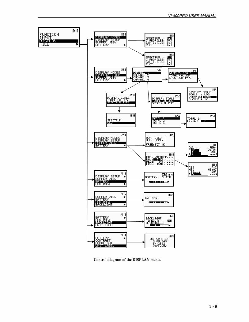
Control diagram of the DISPLAY menus

VI-400PRO USER MANUAL
3 - 10
FILE (from main list)
SAVE: [name of the file] or SAVE NEXT: [name of the file]; In SAVE, the name of the file can be fully edited in the FILE NAME window after pressing <ENTER>. In SAVE NEXT the FILE NAME can be edited in the simplify way by pressing <3333>, <4444> together with <Alt f>; the No results! text is displayed when the instrument has not perform any measurement to save
SAVE OPTIONS (sub-list)
RAM FILE: (position); enables the user to save the measurement results in the special file at RAM memory (the name of the file is defined as a “RAMfile”), this option is useful when remote reading is necessary, e.g. during the long term monitoring; the results are saved all the time in the same space of the units memory; available choices: [√√√√] or [ ]
REPLACE: (position); enables the user to replace the existing files in the instrument’s memory with the files having the same name; available choices: [√√√√] or [ ]
SAVE STAT.: (position); enables the user to save or not to save the calculated statistics along with the measurement results; available choices: [√√√√] or [ ]; position available only in the SLM; in VLM this position does not appear
AUTO SAVE: (position); enables the user to save the measurement results in the instrument’s memory without entering the SAVE or SAVE NEXT position (in order to perform this operation the INT. TIME should be set to at least 10 s); available choices: [√√√√] or [ ]
LOAD (sub-list); enables the user to verify the list of files in the memory and to load the selected one to the working buffer of the instrument; the NO FILES text is displayed when the instrument’s memory is empty
DELETE (sub-list); enables the user to verify the list of files in the memory and to delete the selected one; the NO FILES text is displayed when the instrument’s memory is empty
DELETE ALL (sub-list); enables the user to delete all files saved in the instrument’s memory; the confirmation is required before all files are erased
Are you sure?
DEFRAGMENTATION (sub-list); enables the user to recover the memory previously used by the deleted files; the confirmation is required before this operation is executed Are you sure? The text Defragmentation …unnecessary PRESS ANY KEY is displayed when the instrument’s memory was empty before attempting defragmentation
CLEAR BUFFER (position); enables the user to delete all files saved in the buffer of the instrument; the confirmation is required before all files are erased from the buffer memory Are you sure?
CATALOGUE (sub-list); enables the user to verify the list of files in memory; the NO FILES text is displayed when the instrument’s memory is empty
FREE SPACE (window); informs the user about the size of the available memory for saving measurement results in files and the TOTAL AVAILABLE bytes of the memory (the number displayed in the FREE SPACE will increase by the memory which was previously used by the files that are deleted)
VI-400PRO USER MANUAL
3 - 11
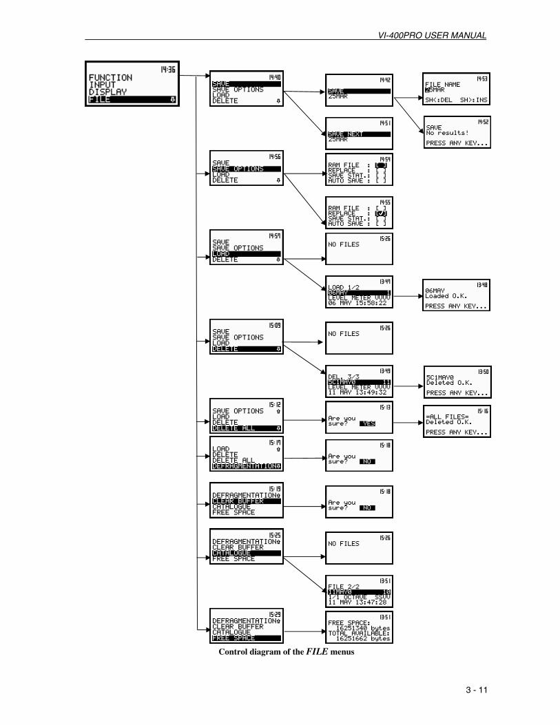
Control diagram of the FILE menus

VI-400PRO USER MANUAL
3 - 12
AUX. FUNCTIONS (from main list)
HAV/WBV CALC. (position);
HAV CALCULATOR (position) enables the user to calculate the various H–A parameters: PARTIAL EAV/ELV, PARTIAL EXPOSURE and DAILY EXPOSURE of vibration. All results are calculated according to the selected standard • RESULTS SEL. (position) enables the user to select files with particular measurement
results. It is possible to select 6 files, which include measurement results with H–A data FILE NAME (position) enables the user to select files with H–A data EXPOSURE TIME (position) defines the time during which measurement
results are extrapolated • PARTIAL EAV/ELV (position) displays the partial result of dose: EAV and ELV results • PARTIAL EXP. (position) displays the EXPOSURE results, for each selected file
separately • DAILY EXPOSURE (position) displays the result of DAILY EXPOSURE results, for each
selected file separately; the result is calculated relatively to EXPOSURE TIME
WBV CALCULATOR (position) used to calculate the various WBV parameters: PARTIAL EAV/ELV, PARTIAL EXPOSURE, DAILY EXPOSURE and DAILY DOSE of vibration; all results are calculated according to the selected standard • RESULTS SEL. (position) enables the user to select files with measurement results. It is
possible to select 6 files, which include measurement results with WBV data FILE NAME (position) enables the user to select 6 files with WBV data EXPOSURE TIME (position) defines the time for the extrapolation of
measurement results. The user can set the time for each file separately • PARTIAL EAV/ELV (position) displays the partial result of dose for each file separately:
EAV and ELV results • PARTIAL RESULTS (position) displays the PARTIAL EXPOSURE results, for each file
separately • DAILY RESULTS (position) displays the results of DAILY EXPOSURE and
DAILY DOSE, for each selected file separately. The result is calculated relatively to EXPOSURE TIME

VI-400PRO USER MANUAL
3 - 13
Control diagram of the AUX. FUNCTION menus

VI-400PRO USER MANUAL
3 - 14
SETUP (from main list)
TIMER (sub-list)
TIME (position); enables the user to set a time the instrument will automatically turn itself on
RTC (sub-list)
RTC (position); enables the user to set the internal real time clock of the instrument
FIELD CORRECTION (sub-list) available only in sound meter mode
FIELD CORRECTION (position); available values of the compensation required when the sound measurements performed are in the diffuse field condition: FREE or DIFFUSE
USER FILTERS (sub-list) VIBR. FILTERS
• VIEW o VIEW enables the user to select which filter should be viewed; the available
options are VUSR1, VUSR2, VUSR3 and any other transmitted to the instrument via computer interface After pressing <ENTER> another sub-list opens containing the values of filters used in 1/1 OCTAVE or 1/3 OCTAVE analysis and saved under the name USER1, USER2, USER3 or any other
• EDIT o EDIT enables the user to select which filters should be edited; the available
options are: VUSR1, VUSR2, VUSR3 or any other transmitted to the instrument via computer interface
o After pressing <ENTER> another sub-list opens containing the values of the filters used in 1/1 OCTAVE or 1/3 OCTAVE analysis; the user can set the values of correcting coefficients for all 1/3 OCTAVE filters:
0.80 Hz: available values of 0.8 Hz centre frequency filter: -100.0dB ... 100.0dB
... … 20.0kHz: available values of 20 kHz centre frequency filter: -100.0dB ...
100.0dB • CLEAR (position)
o CLEAR enables the user to select which filters should be cleared; the available options are: ALL, VUSR1, VUSR2, VUSR3 or any other
SOUND FILTERS • VIEW
o VIEW enables the user to select which filter should be viewed; the available options are SUSR1, SUSR2, SUSR3 and any other transmitted to the instrument via computer interface After pressing <ENTER> another sub-list opens containing the values of filters used in 1/1 OCTAVE or 1/3 OCTAVE analysis and saved under the name USER1, USER2, USER3 or any other
• EDIT o EDIT enables the user to select which filters should be edited; the available
options are: SUSR1, SUSR2, SUSR3 or any other transmitted to the instrument via computer interface
o After pressing <ENTER> another sub-list opens containing the values of the filters used in 1/1 OCTAVE or 1/3 OCTAVE analysis; the user can set the values of correcting coefficients for all 1/3 OCTAVE filters:
0.80 Hz: available values of 0.8 Hz centre frequency filter: -100.0dB ... 100.0dB
...

VI-400PRO USER MANUAL
3 - 15
… 20.0kHz: available values of 20 kHz centre frequency filter: -100.0dB ...
100.0dB • CLEAR (position)
o CLEAR enables the user to select which filters should be cleared; the available options are: ALL, SUSR1, SUSR2, SUSR3 or any other
STAT. LEVELS (sub-list) available only in the sound meter mode. Enables the user to select ten separate values Ni, i = 1,…, 10, of the LN statistics to be saved with the main results, in a file
N1 = (position); the first value of the LN statistics to be saved with the main results in a file; available values: any number from 1 to 99
…
N10 = (position); the tenth value of the LN statistics to be saved with the main results in a file; available values: any number from 1 to 99
EXT. I/O SETUP (sub-list) enables the user to connect the instrument with another device and define the working mode of the AC / Int. connection
MODE o ANALOG (position) in this mode the meter can output signals from the selected
CHANNEL to the connected device; the user may choose CHANNEL 1, 2, 3 or 4 o DIGITAL IN (position) in this mode the device connected to the AC/Int.
connection will trigger the VI-400Pro to undertake measurements. This mode is used in conjunction with the EXT.TRIGGER function
o DIGITAL OUT (position) in this mode the VI-400Pro is connected to some external device which is triggered by the VI-400Pro to measure. This mode is used in conjunction with the TRIGGER PULSE function
SHIFT MODE (sub-list)
SHIFT: (position); available modes of the <Alt f> push-button: Shift or 2nd Fun.
ST/SP: (position); available modes of the <START / STOP> push-button: Normal or Inverse Note: If Inverse mode is selected the Start / Stop function will only occur when the <START / STOP> push-button is used in conjunction with the <Alt f> push-button
CLEAR SETUP (position); enables the user to return to the factory default settings of the instrument; the confirmation has to be done before the execution of this function Are you sure?
RMS INTEGRATION (sub-list)
RMS INTEGRATION: (position); available values of detector’s type: LINEAR or EXPONENTIAL
REFERENCE LEVEL (sub-list); available choices: VIBRATION or SOUND
VIBRATION • ACC - it enables the user to set the reference level of the acceleration for the
logarithmic scale (the results expressed in dB - decibels), available levels are from 1 µm/s2 to 100 µm/s2
• VEL - it enables the user to set the reference level of the velocity for the logarithmic scale (the results expressed in dB - decibels), available levels are from 1 nm/s to 100 nm/s
• DIL - it enables the user to set the reference level of the displacement for the logarithmic scale (the results expressed in dB - decibels), available levels are from 1 pm to 100 pm

VI-400PRO USER MANUAL
3 - 16
SOUND • REFERENCE LEVEL for sound measurements is equal to 20 µPa
VIBRATION UNITS (sub-list) only relevant for vibration measurements
VIBRATION UNITS (position); enables the user to set METRIC (example m/s2, m/s, m) or NON-METRIC units (example g, ips, mil)
WARNINGS (sub-list)
RES.NOT SAVE: (position); enables the user to turn on or off the warning that the results of the measurement were not saved in memory; available values: [√√√√] or [ ]
VECTOR DEF. (sub-list) enables the user to select coefficients needed to calculate vibration vector, taken into account during the calculation of the measurement results.
K1, K2, K3, K4: the coefficients set in the instrument, these are used to calculate VECTO.
HAV/WBV DOSE (sub-list) enables the user to select parameters relevant the EXPOSURE and VIBRATION DOSE measurements.
MEASURE DOSE (position) enables the user to switch on (ENABLED) or switch off (DISABLED) the measurement of vibration dose.
EXPOSURE TIME (position) enables the user to set the exposure time of the vibration signal.
AXIS SETUP (position) enables the user to assign each axis of accelerometer to the channel number.
STANDARDS (position) enables the user to select the standard, which determines the limits used for measured vibration. Choices UNITED KINGDOM (U.K.), ITALY, POLAND or USER are available in firmware version 2.17 of the VI-400Pro

VI-400PRO USER MANUAL
3 - 17

VI-400PRO USER MANUAL
3 - 18
Control diagram of the SETUP menus

VI-400PRO USER MANUAL
3 - 19
3.2. POWERING THE INSTRUMENT
The VI-400PRO is powered from four internal replaceable “AA” alkaline batteries. For the external power operation an adapter should be connected to the Power socket located on the bottom cover of the instrument.
Fully charged batteries will ensures more than 8 hours of the continuous operation of the instrument (with the backlight off). The operation time is decreased about 20 % with the backlight switched on. The battery condition can be checked by means of the BATTERY function. It is also presented continuously (if the internal AA batteries are used) on the display by means of the “Battery” icon. When using the external power supply the “Battery” icon is not displayed on the screen but the red “Ext.Pwr” light will be on.
a) b)
(a) The display in 3 PROFILES mode with the battery icon. (b) DISPLAY\BATTERY position
Notice: When the “AA” batteries become too low the VI-400Pro will turn itself off ! To avoid this situation it is recommended to replace the “AA” batteries before they become too low or to connect the external power supply.
The backlight of the display can be activated by means of the < > push-button. To conserve
battery power, in normal "day-light" operation it is recommended to keep the backlight off. The user can also set the TIMEOUT position in the BACKLIGHT sub-list of the DISPLAY list, doing so will cause the backlight to automatically turn off 30 seconds after it has been turned on .

VI-400PRO USER MANUAL
3 - 20
3.3. INITIAL SETUP OF THE INSTRUMENT
When the VI-400Pro is first turned on it briefly displays the manufacture and model number. It then displays “WARM UP TIME please wait: nns” where “nn” is a 60 second countdown. It then enters the sound or vibration mode for channel 1 (depending on which mode was used when the unit was turned off). The default display mode for result’s presentation is one profile (see Chapter 4 for details).
The view of the displays after switching on the instrument
To start the measurements the user has to press <START /STOP> push-button. The result of the measurement is displayed, in one profile mode, using large easily visible characters. Under the result an analog bar indicator is presented. On the left side of the display, the channel being displayed (CH1, CH 2, CH 3 or CH 4), the function name (SPL, LEQ, SEL, Ld, Ltm3, Ltm5, Lxx, PEAK, MAX or MIN for sound measurements and RMS, VDV, PEAK, P–P or MTVV for vibration measurements), for sound measurement the third line shows the unit of the measurement with weighted filter (dB for LIN filter, dB A for A filter, dB C for C filter or dB G for G filter) and in the fourth line – the detector time constant (IMP., FAST or SLOW) are presented. For vibration measurements the fourth line displays the type of weighted filter selected in the channel (HP1, HP3, HP10, Vel1, Vel3, Vel10, VelMF, Dil1, Dil3, Dil10, W–Bxy, W–Bz, H–A, W-Bc, KB, Wk, Wd, Wc or Wj).
a) b) c)
The view of the display in one profile (a) and 3 PROFILES display mode (b), (c)
a) b) c)
The view of the display in one profile (a) and 3 PROFILES display mode with the vibration measurement (channel 1 and 2) results expressed in METRIC (b) and NON-METRIC units (c)
The results of the measurements can be presented in One profile, 3 PROFILES, STATISTICS and PLOT display modes. It is possible to change the display mode pressing the <5555> or <6666> push-buttons together with <Alt f> . In 3 PROFILES display mode the results of the measurement from three channels are displayed simultaneously. The units, weighted filter and detector time constant are also shown. The factory default settings of the channels, are as follows:
CHANNEL 1 - VIBR. mode; 316 m/s2 range; HP1 weighting filter (FILTER: HP1), 1.0 s RMS detector (DETECT.: 1.0s);
CHANNEL 2 - VIBR. mode; 316 m/s2 range; HP3 weighting filter (FILTER: HP3), 1.0 s RMS detector (DETECT.: 1.0s);
CHANNEL 3 - VIBR. mode; 316 m/s2 range; HP10 weighting filter (FILTER: HP10), 1.0 s RMS detector (DETECT.: 1.0s);

VI-400PRO USER MANUAL
3 - 21
CHANNEL 4 - SOUND mode; 130 dB range; A weighting filter (FILTER: A), FAST type of the RMS detector (DETECTOR: FAST).
The user can change all settings mentioned above using CHANNEL x sub-list of the INPUT list. The instrument will remember all changes. It is possible to return to factory default settings in the CLEAR SETUP position available in the SETUP list.
In addition to sound level meter (SLM) or vibration level meter (VLM) modes, the VI-400Pro can also be used as a 1/1 OCTAVE, 1/3 OCTAVE, or FFT analyzer. In SLM (or VLM) operating mode of the unit, the one profile display mode shows a solid vertical line separating the measurement result from its description. 3 PROFILES display mode two solid horizontal lines are used to separate the measurement results from different channels. In modes other than SLM (or VLM) the separating lines, mentioned above, are dotted.
a) b)
The view of the display in one profile (a) and 3 PROFILES display mode (b) for results which are not from the SLM or VLM mode
Notice: See Chapters 4 and 5 for more details concerning different settings.
Additional information about the instrument’s state are given by means of a row of icon’s at the top of the display. The meanings of these icons are as follows:
- “Bell” is displayed as a WARNING in several situations. When the ”Bell” icon appears the user should pay attention to the state of the instrument. Typically some user’s action is required (for example: a low battery state, or too high an input signal - OVERLOAD etc.).
The view of the display with the “Bell” icon
- “Loudspeaker” icon is displayed at the start of and during measurement.
The view of the display with the “Loudspeaker” icon
- “Vertical bars” icon corresponds to the current input signal level (it is related to the maximum measured value over the last second). The sign means that the level of the signal was from 0.1 dB to 10 dB higher then the current measurement range. For example; in SLM mode, where the range is

VI-400PRO USER MANUAL
3 - 22
130 dB, the sign would result if the measurement were from 130.1 dB to 140 dB. The ”Bell” icon (overlaod) appears when the signal surpasses the measurement range by more than 7.5 dB (cf. Fig. below).
a) b) c)
d) e)
f) g) h) The view of the display in the SLM mode without the “Vertical bars” icon (a); with one “Vertical bar” (b);
with two “Vertical bars”(c), (d); with three “Vertical bars” (e),(f); with three “Vertical bars” and the sign (g); with the “Bell” icon overload (i)
The number of the ”Vertical bars” on the display depends on the level of the measured signal, the selected mode (SLM, VLM, 1/1 OCTAVE, 1/3 OCTAVE or FFT analysis, etc) and the calibration factor. The limits of the signal causing the different icon’s indication for the calibration factor equal to 0 dB are presented in the Table 3.1 for sound measurements and in Table 3.2 – for vibration measurements. Non-zero calibration factors will cause a shift of the limits given in the tables.
Notice: The “Bell” icon is used as an indicator of an overload.
When the level of the measured signal is below the measuring range “UNDERRANGE” appears below the measurement result in one profile display mode. In 3 PROFILES display mode a downward pointing arrow is used to indicate “underrange”.
Notice: The UNDERRANGE is indicated only in the case of sound measurements.
The view of the displays, in SLM mode, when the level of the signal is too low
Table 3.1. The limits of the signal causing different icon indications during sound measurements

VI-400PRO USER MANUAL
3 - 23
SLM 1/1 OCTAVE, 1/3 OCTAVE or FFT ANALYSIS INDICATOR
130 dB range 105 dB range 130 dB range
“Bell” ≥ 137.5 dB ≥ 114.5 dB ≥ 137.5 dB
+ 3 “Bars” ≥ 130.1 dB ≥ 105.1 dB ≥ 130.1 dB
3 “Bars” 100.1 dB – 130.0 dB 80.1 dB – 105.0 dB 105.1 dB – 130.0 dB
2 “Bars” 70.1 dB – 100.0 dB 55.1 dB – 80.0 dB 80.1 dB – 105.0 dB
1 “Bar” 40.1 dB – 70.0 dB 30.1 dB – 55.0 dB 55.1 dB – 80.0 dB
≤ 40.0 dB ≤ 30.0 dB ≤ 55.0 dB
UNDERRANGE < 24.0 dB A < 24.0 dB A < 44.0 dB A
UNDERRANGE < 24.0 dB C < 24.0 dB C < 42.0 dB C
UNDERRANGE < 30.0 dB < 30.0 dB < 48.0 dB
Table 3.2. The limits of the signal causing different icon indications during vibration measurements (values expressed in decibels are calculated with the assumption that the reference level is equal to 1 µm/s2)
VLM, 1/1 OCTAVE, 1/3 OCTAVE or FFT ANALYSIS INDICATOR
17.8 m/s2 range
145 dB range
316 m/s2 range
170 dB range
“Bell” ≥ 53.1 m/s2
≥ 154.5 dB
≥ 750 m/s2
≥ 177.5 dB
+ 3 “Bars” ≥ 18.0 m/s2
≥ 145.1 dB
≥ 320 m/s2
≥ 170.1 dB
3 “Bars” 1.01 m/s2 – 17.8 m/s2 120.1 dB – 145.0 dB
18.0 m/s2 – 316 m/s2 145.1 dB – 170.0 dB
12 “Bars” 56.9 mm/s2 – 1.00 m/s2
95.1 dB – 120.0 dB 1.01 m/s2 – 17.8 m/s2 120.1 dB – 145.0 dB
1 “Bar” 3.20 mm/s2 – 56.2 mms/2
70.1 dB – 95.0 dB 56.9 mm/s2 – 1.00 m/s2
95.1 dB – 120.0 dB
≤ 3.16 mm/s2
≤ 70.0 dB
≤ 56.2 mm/s2
≤ 95.0 dB
- “Tree” icon is displayed in a flashing mode together with the “Loudspeaker” when the measurement is started, the trigger is switched on and the level of the signal is too low to start the registration.
The view of the display with the “Tree” and “Loudspeaker” icon

VI-400PRO USER MANUAL
3 - 24
- “Envelope” icon is presented when the current measurement results are logged in the instrument’s buffer. Together with this icon the “Loudspeaker” icon is always displayed. When the “Envelope” icon starts flashing, it means that the instrument’s whole buffer is filled. The new measurement result is not saved. If the user wants to save these results, he has to first use the CLEAR BUFFER function from the FILE list, this removes all results from the buffer memory.
a) b)
The view of the display with the icons: “Envelope” and with internal real time clock (a); “Battery” (b)
- “Battery” icon corresponds to the state of the internal battery.
- “Clock” icon displays the current time when the colon is flashing or the current time of the measurement (set in the INT. TIME) if the colon is not flashing. The current time of the measurement is displayed after the start of the measurement and is also shown during pause (after pressing the <PAUSE> push-button). The clock icon is also updated when the last result has been suspended using <PAUSE>. When the 2nd Func. mode is selected (SHIFT MODE sub-list of the SETUP list) the flashing text “2n dF” will display instead of the clock . This flashing “2n dF” text will be displayed from when the <Alt f> push button is pressed until another push-button is pressed.
Notice: The time of the measurement is displayed in MM:SS format for the range from 1 sec. to 39 minutes 59 seconds. Values 40 minutes or greater are shown in HH:MM format (i.e. 00:40).
Notice: In all modes of the instrument the “Clock” icons are always shown on the display.
Notice: The “Battery” Icon is displayed only while internal (“AA”) batteries are used. When the meter is powered by an external power supply the “Battery” icon is not displayed
Notice: If the user modifes the “DEFAULT SETUP” and turns the unit off, those changes will be saved and reused when the unit is turned back on.

VI-400PRO USER MANUAL
4 - 1
4. MEASUREMENT FUNCTIONS OF THE INSTRUMENT The VI-400PRO is a unique pocket-sized 4-channels instrument combining functions of a sound
level meter (SLM), a vibration level meter (VLM), 1/1 OCTAVE ,1/3 OCTAVE and FFT real time analyzer. The VI-400Pro conforms to type 1 accuracy.
Using state of the art digital signal processing, the instrument has four (4) independent sound / vibration level meter channels, which perform signal measurements with the selectable combination of:
• A, C, LIN (Z) weighting filters and SLOW, FAST or IMPULSE RMS detectors - for sound and
• HP1, HP3, HP10, W–Bxy, W–Bz, H–A, W–Bc, KB, Wk, Wd, Wc or Wj weighting filters and 100 ms, 125 ms, 200 ms, 500 ms, 1 s, 2 s, 5 s or 10 s RMS detectors - for vibration.
1/1 OCTAVE, 1/3 OCTAVE or FFT analysis works simultaneously with the channels mentioned above.
Acoustic measurements of SPL, LEQ, SEL, Ld(en) (period of measurement d-day, e-evening, n-night), Ltm3, Ltm5, LN (statistics), PEAK, MAX, MIN and time history are performed simultaneously in all channels (refer to Appendix D.1.1 for the definitions).
Vibration measurements of RMS, VDV, PEAK, P–P, MTVV, MAX and time history are performed simultaneously in all channels (refer to Appendix D.1.2 for the definitions).
The measurement results can be presented on the display in different formats depending on the selected function and parameter settings. For sound / vibration level meter function the following display modes are available:
• One Profile, 3 PROFILES, STATISTICS and PLOT.
• For 1/1 OCTAVE, 1/3 OCTAVE or FFT analysis the possibility to present the spectra is also available (SPECTRUM mode).
• The selection of the display mode is made by pressing <5555> or <6666>.
• Scrolling between channels is possible by pressing <Alt f> and <5555> or <Alt f> and <6666> (in One profile, 4 PROFILES or STATISTICS modes).
• Scrolling between the results of a selected channel is possible by pressing <3333>, <4444> (in One profile or 3 PROFILES modes).
• Changing the statistics class (statistics are only available for sound measurements), the 1/1 octave or 1/3 octave filter, the FFT line and the value in the buffer is done by pressing <3333> or <4444> which moves the cursor in STATISTICS, SPECTRUM and PLOT modes.
• Pressing < Altf > and <5555> or < Altf > and <6666> allows the user to change the relation between the vertical and horizontal axis of results in the SPECTRUM and PLOT modes.
• For 1/1 OCTAVE or 1/3 OCTAVE analysis mode of acoustic signals, pressing <ENTER> in the SPECTRUM mode while viewing results allows the user to observe the statistical analysis performed for the selected 1/1 OCTAVE or 1/3 OCTAVE filter. To return to the SPECTRUM mode press <ESC>. The statistical analysis is not performed for the vibration signal.
• While reviewing 1/1 OCTAVE or 1/3 OCTAVE statistical analysis results of the acoustic signals, < Altf > and <5555> or < Altf > and <6666> allows the user to change the selected 1/1 OCTAVE or 1/3 OCTAVE filters. Pressing <3333>or <4444> changes the cursor position of the LN value displayed.

VI-400PRO USER MANUAL
4 - 2
The acoustic measurement channel consists of the VI-400Pro, the preamplifier part number 072-028 and the B&K4936 microphone part number 059-523. The calibration of the sound measurement channels should be performed periodically. The calibration procedure is described in Chapter 4.1.
The vibration measurement channel consists of the VI-400Pro and an appropriate accelerometer. This channel is factory calibrated and prepared for the work in the standard environmental conditions. The calibration procedure is described in Chapter 4.1.
The main functions of the VI-400Pro are the measurement of sound level using a microphone and preamp and the measurement of vibration level using an accelerometer. 1/1 OCTAVE, 1/3 OCTAVE analysis and narrow-band frequency analysis (FFT) can be selected for both sound level and vibration level measurements.
The detailed description of
• the calibration procedure is given in Chapter 4.1,
• the measurement of signal’s level is described in Chapter 4.2,
• 1/1 OCTAVE analysis is given in Chapter 4.4,
• 1/3 OCTAVE analysis is described in Chapter 4.5,
The additional functions of the instrument, such as, presenting measurement results (DISPLAY list), the setting parameters (SETUP list) and storing measurement results (FILE list), are described in Chapter 5.

VI-400PRO USER MANUAL
4 - 3
4.1. CALIBRATION The instrument is factory calibrated with the supplied accelerometer and microphone for standard
environmental conditions. Each of four channels should be calibrated separately. For situations where the absolute vibration or sound level value is important, a calibration of the measurement channel should be conducted by the user. This is due to the fact that the accelerometer or microphone sensitivity is a function of temperature, ambient pressure and humidity.
To select a calibration function the user enters the FUNCTION list by pressing <MENU>, selecting the FUNCTION text using <5555> or <6666> (or <3333>, <4444>) and pressing <ENTER>. The FUNCTION list contains two sub-lists: MEASUR. FUNCTION and CALIBRATION. The user selects the CALIBRATION sub-list using <5555>, <6666> or <3333>, <4444> to highlight CALIBRATION and pressing <ENTER>. Then the user chooses the channel to calibrate.
a) b)
c) d)
The view of the displays with the main list, the FUNCTION text selected (a), the FUNCTION list opened (b), the CALIBRATION text selected (c) and CHANNEL selected (d)
Once the CHANNEL is selected a sub-list with two options is available: BY SENSITIVITY or BY
MEASUREMENT. BY SENSITIVITY allows the user to directly enter the sensitivity values for the specific accelerometer or microphone being used. BY MEASUREMENT allows the user to present the accelerometer or microphone with a known signal from a calibrator. Measurement calibration of an accelerometer can be performed using a handheld vibration calibrator/shaker such as our model 072-018. Measurement calibration of a microphone can be performed using an acoustical calibrator such as our model QC-20.
a) b)
The view of the displays in the CALIBRATION sub-list (path: MENU / FUNCTION / CALIBRATION / CHANNEL X) with BY SENSITIVITY selected (a), and BY MEASUREMENT selected (b).
Note: The calibration level and the calibration result is expressed in different units depending on the settings of the instrument. The metric or non-metric vibration units are set in the VIBRATION UNITS window of the SETUP list. Additionally, the linear or logarithmic units are set in the DISPLAY SCALE sub-list of the DISPLAY list.

VI-400PRO USER MANUAL
4 - 4
4.1.1. Calibration by sensitivity
Calibration BY SENSITIVITY for vibration signal
The calibration BY SENSITIVITY for an accelerometer can be conducted in the following way:
1. Select BY SENSITIVITY from the CALIBRATION sub-list and press <ENTER>.
The view of the displays with the selected calibration mode and after pressing <ENTER>
2. Input the sensitivity of the accelerometer, taken from its calibration card, using <3333>, <4444> and then press <ENTER>.
The calibration factor is calculated, after pressing <ENTER>, in the relation to 10.0 mV / ms-2. To exit from this screen without changing the sensitivity press <ESC>. When the sensitivity of the accelerometer is greater than 10.0 mV / ms-2 the calibration factor will be negative.
a) b)
The view of the displays while setting the sensitivity greater then 10.0 mV / ms-2 (a) and after pressing <ENTER> with the new calibration factor calculated (b)
When the sensitivity of the accelerometer is less than 10.0 mV / ms-2 the corresponding calibration factor will be positive.
a) b)
The view of the displays while setting the sensitivity less than 10.0 mV / ms-2 (a) and after pressing <ENTER> with the new calibration factor calculated (b)
The lowest sensitivity value allowed is 10.0 µV / ms-2 (it will result in a calibration factor of 60.0 dB). The greatest sensitivity value allowed is 10.0 V / ms-2 (it will result in a calibration factor of -60.0 dB).
Note: The calibration factor is always added to the results in the VIBRATION LEVEL METER mode (VLM), 1/1 OCTAVE, 1/3 OCTAVE and the FFT analysis modes.
To return to the CALIBRATION sub-list the user has to press <ESC>.

VI-400PRO USER MANUAL
4 - 5
Calibration BY SENSITIVITY for acoustic signal
The calibration BY SENSITIVITY for a microphone can be conducted in the following way:
1. Select BY SENSITIVITY from the CALIBRATION sub-list and press <ENTER>.
The view of the displays with the selected calibration mode and after pressing <ENTER>
2. Set the sensitivity of the microphone, taken from its calibration card, using the <3333>, <4444> push-buttons and then press <ENTER>.
The calibration factor is calculated, after pressing <ENTER>, in the relation to 50.0 mV / Pa. To exit from this screen without changing the calibration factor press <ESC>. For a microphone sensitivity greater than 50.0 mV / Pa the resulting calibration factor is negative.
a) b)
The view of the displays while setting the sensitivity greater then 50.0 mV / Pa (a) and after pressing <ENTER> with the resulting calibration factor calculated (b)
For a microphone sensitivity less than 50.0 mV / Pa the resulting calibration factor is positive.
a) b)
The view of the displays while setting the sensitivity less than 50.0 mV / Pa (a) and after pressing <ENTER> with the resulting calibration factor calculated (b)
The lowest microphone sensitivity value allowed is 50.0 µV / Pa (it will result in a calibration factor of 60.0 dB). The greatest microphone sensitivity value allowed is 50.0 V / Pa (it will result in a calibration factor of -60.0 dB).
Notice: The calibration factor is always added to the results of sound level measurements and sound analysis.
To return to the CALIBRATION sub-list the user has to press <ESC>.

VI-400PRO USER MANUAL
4 - 6
4.1.2. The calibration BY MEASUREMENT
Calibration BY MEASUREMENT for vibration signal
The calibration BY MEASUREMENT can be conducted in the following way:
1. Select BY MEASUREMENT from the CALIBRATION sub-list and press <ENTER>.
a) b)
The view of the displays with the selected calibration mode (a), and after entering this mode (b). 2. Attach the vibration calibrator to the instrument’s accelerometer.
3. Switch on the calibrator and wait a few seconds before starting the calibration measurement.
4. Start the calibration measurement by pressing <START / STOP>.
The calibration measurement starts after a 5 second delay countdown. The measurement time is also predefined to 5 seconds. During the calibration period, <ESC> and <PAUSE> do not operate but it is possible to stop the measurement using <START / STOP>. Waiting for the calibration measurement to begin, a DELAY is counted down and the text “CALIBRATION” changes.
The view of the displays while the instrument is waiting for the calibration measurement to commence
During the calibration measurement, the text changes to cal. measure / CAL. MEASURE. At the end of the measurement, the result is displayed on the display in the bottom line.
The displays during the calibration measurements
The displays after the calibration measurements

VI-400PRO USER MANUAL
4 - 7
The calibration procedure should be repeated a few times to ensure the integrity of the calibration. The results obtained should be almost identical (with ±0.1 dB). Possible reasons for unstable results are as follows: • the calibrator is not properly attached to the instrument, • there are external disturbances, • the calibrator or the measurement channel (the accelerometer or the instrument itself) are damaged.
Note: During the calibration period, external disturbances (vibrations or acoustic noise) should not exceed 100 dB.
5. Press <ENTER> to accept the measurement result.
After pressing <ENTER> the calibration factor is calculated, stored and displayed (cf. Fig. below).
The displays after pressing <ENTER> (after calculation of the calibration factor value)
Note: The calibration factor is always added to the measurement results in the level meter mode and coming from the frequency analysis (1/1 OCTAVE, 1/3 OCTAVE and FFT).
Calibration BY MEASUREMENT for acoustic signal
The calibration for sound measurements can be done in the following way:
1. Attach the acoustic calibrator QC-20 (or equivalent 94 dB / 1000 Hz) to the microphone of the instrument.
Notice: Before starting the calibration measurement, the user has to set the level of the signal generated by the given calibrator. This is done using <3333>, <4444> in the CAL. LEVEL position of BY MEASUREMENT sub-list. The output level of the calibrator should be marked on a label affixed to the calibrator.
2. Switch on the calibrator and wait a couple of seconds before starting the calibration measurement.
3. Start the calibration measurement by pressing <START / STOP>.
The calibration measurement starts after a 5 second delay countdown. The measurement time is also predefined to 5 seconds. During the calibration period, <ESC> and <PAUSE> do not operate but it is possible to stop the measurement using the <START / STOP>. It is not recommended to stop the calibration measurement before programmed 5 second period completes !

VI-400PRO USER MANUAL
4 - 8
The view of the displays during the calibration measurement
Waiting for the start of the calibration measurement the DELAY is counted down on the display and the CALIBRATION text toggles from big small letters. During the measurements the cal. measure text toggles from big small letters. At the end of the measurement the calibration result is displayed on the bottom line of the display.
It is recommended to repeat the calibration measurement a few times. The obtained results should be almost the same (with ±0.4 dB). Possible reasons for the unstable results are as follows:
• the calibrator is not properly attached to the instrument, • there are external disturbances, • the calibrator or the measurement channel (the microphone, the preamplifier or the instrument
itself) are damaged.
Notice: During the calibration measurement external disturbances (acoustic noise or vibrations) should not exceed the value of 100 dB.
4. Press the <ENTER> push-button to accept the measurement result.
After pressing <ENTER> the calibration factor is calculated, stored and displayed (cf. next Figure).
Notice: The user has to press <ESC> in order to quit the calibration procedure without saving the calibration factor.
a) b)
The view of the displays after the measurements (a) and after the acceptance of the value of the calibration factor (b)
Notice: The calibration factor is always added to the measurement results of level meter mode and the frequency analysis results of the acoustic signal (1/1 OCTAVE, 1/3 OCTAVE and FFT).

VI-400PRO USER MANUAL
4 - 9
4.2. LEVEL METER
The LEVEL METER mode provides the user the function of SLM (Sound Level Meter) meeting the IEC 651, IEC 804 and IEC 61672-1 standards for Type 1 accuracy and/or the function of VLM (Vibration Level Meter) meeting the ISO 8041 standard. The instrument can also be used for the long-term acoustic and vibration monitoring logging the results in the large 32MB memory.
To select the LM mode (path: MENU / FUNCTION / MEASUR. FUNCTION / LEVEL METER) the user will select <MENU>, use <5555>, <6666> (or <3333>, <4444>) to select FUNCTION and press <ENTER>. The FUNCTION list contains two sub-lists: MEASUR. FUNCTION and CALIBRATION. Next, the user will select MEASUR. FUNCTION using <5555>, <6666> or <3333>, <4444> and then press <ENTER>.
a) b)
The view of the displays with the main list, the FUNCTION selected (a) and the FUNCTION list opened; the MEASUR. FUNCTION selected (b)
After entering the MEASUR. FUNCTION sub-list, the set of the available functions appears on the
display. Currently active function is marked by the special character “ “
The view of the displays in the MEASUR. FUNCTION (path: MENU/ FUNCTION / MEASUR. FUNCTION) sub-list; the selection of the measurement mode
The LM mode is selected by placing the special character “ “in the line with the LEVEL METER
text. The position of the character can be changed using <5555>, <6666> (or <3333>, <4444>). Press <ENTER> to accept LEVEL METER mode and close the MEASUR. FUNCTION sub-list.
Notice: The instrument mode can not be changed during measurements. In such instance the display shows: “measurement in progress / MEASUREMENT IN PROGRESS” for about 3 seconds. To change the instrument mode the measurement must be completed!
A distinguishing feature of the VI-400Pro is that sound / vibration is always measured in four separate sound / vibration level meter channels working independently.
Notice: The LEVEL METER is a main mode of the instrument. In the LM mode there is no simultaneous access to 1/1 OCTAVE or 1/3 OCTAVE analysis.
For each of the channels the RMS detector type and the weighting filter can be defined independently (see the INPUT list).
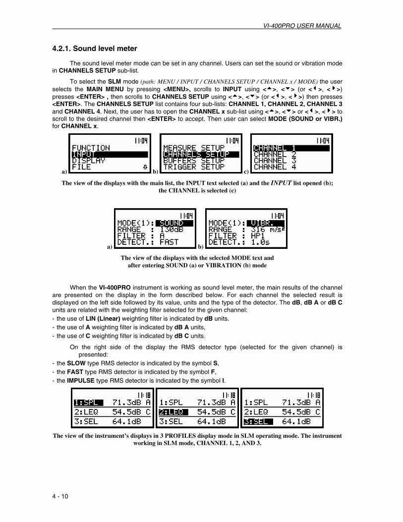
VI-400PRO USER MANUAL
4 - 10
4.2.1. Sound level meter The sound level meter mode can be set in any channel. Users can set the sound or vibration mode
in CHANNELS SETUP sub-list.
To select the SLM mode (path: MENU / INPUT / CHANNELS SETUP / CHANNEL x / MODE) the user selects the MAIN MENU by pressing <MENU>, scrolls to INPUT using <5555>, <6666> (or <3333>, <4444>) presses <ENTER> , then scrolls to CHANNELS SETUP using <5555>, <6666> (or <3333>, <4444>) then presses <ENTER>. The CHANNELS SETUP list contains four sub-lists: CHANNEL 1, CHANNEL 2, CHANNEL 3 and CHANNEL 4. Next, the user has to open the CHANNEL x sub-list using <5555>, <6666> or <3333>, <4444> to scroll to the desired channel then <ENTER> to accept. Then user can select MODE (SOUND or VIBR.) for CHANNEL x.
a) b) c)
The view of the displays with the main list, the INPUT text selected (a) and the INPUT list opened (b); the CHANNEL is selected (c)
a) b)
The view of the displays with the selected MODE text and after entering SOUND (a) or VIBRATION (b) mode
When the VI-400PRO instrument is working as sound level meter, the main results of the channel
are presented on the display in the form described below. For each channel the selected result is displayed on the left side followed by its value, units and the type of the detector. The dB, dB A or dB C units are related with the weighting filter selected for the given channel: - the use of LIN (Linear) weighting filter is indicated by dB units. - the use of A weighting filter is indicated by dB A units, - the use of C weighting filter is indicated by dB C units.
On the right side of the display the RMS detector type (selected for the given channel) is presented:
- the SLOW type RMS detector is indicated by the symbol S, - the FAST type RMS detector is indicated by the symbol F, - the IMPULSE type RMS detector is indicated by the symbol I.
The view of the instrument’s displays in 3 PROFILES display mode in SLM operating mode. The instrument working in SLM mode, CHANNEL 1, 2, AND 3.

VI-400PRO USER MANUAL
4 - 11
Notice: The PEAK result never depends on the detector time constant. The LEQ, SEL and Ld(en) results do not depend on the detector time constant if the LINEAR option was selected in the RMS INTEGRATION position of the SETUP list. The LEQ, SEL and Ld(en) results depend on the detector time constant if the EXPONENTIAL option was selected in the RMS INTEGRATION position of the SETUP.
Each of the sound channels simultaneously measure the following results, (see Appendix D for the
definitions): - PEAK, - MAX, - MIN, - SPL, (displayed SPL is the largest result, of the selected RMS detector, measured over the last
second), - LEQ, - SEL, - Ldx,(x = period of measurement d-day, e-evening, n-night), - Ltm3, - Ltm5, - LN,(where N is statistics class, from 1 to 99, selected by the user), - Current measurement time (available in the result’s field only in 3 PROFILES display mode).
The view of the instrument’s display in 3 PROFILES display mode with the current measurement time for
CHANNEL 1 in SLM mode
Notice: Switching between the channels is possible by pressing <Alt f> with <5555> or <6666>. Switching between the results for the selected channel is made by pressing just <3333>or <4444>. To change the nn in statistical level the user has to press <Alt f> with <3333>or <4444> (in one profile or 3 PROFILES display mode).
By pressing <5555> or <6666> the user can switch the display mode to:
- One profile, - 3 PROFILES, - STATISTICS, - PLOT (from the channel the results of the measurement were stored; the number of the channel is
displayed along with the name of the result, i.e. CH 1 - PEAK, CH 2 - RMS, CH 3 - MAX, etc).
Notice: The user can select the currently active display mode by means of the DISPLAY MODES sub-list of the DISPLAY list. The activation of a mode is indicated by the graphical symbol placed in the proper line of the DISPLAY MODES sub-list. More details about the display modes are given in the description of the DISPLAY list in the Chapter 5.

VI-400PRO USER MANUAL
4 - 12
a) b)
The view of the displays with the DISPLAY MODES (path: MENU / DISPLAY / DISPLAY MODES) sub-list opened; 3 PROFILE, STATISTICS and PLOT checked on (a) and only PLOT checked on (b)
One profile mode of measurement results presentation This is the main mode of presentation and can not be switched off. In One profile mode the
selected result is presented in the middle of the display in easily visible format. The length of the horizontal bar graph placed under the digital value corresponds to the measured result. If the level of the measured signal is too small the UNDERRANGE text is displayed in the place of the horizontal bar graph. This text disappears after stopping the measurement using <START / STOP> or <PAUSE>. In this mode the parameters; channel number, displayed value, weighting filter with units and RMS detector type are presented in four lines on the right side of the display. A vertical line separates the digital value from the parameters. This vertical line is solid for sound level meter mode and doted in other modes. The PEAK result never depends on the detector time constant, so the fourth line for this result always remains empty. The LEQ, SEL and Ld(en) results depend on the detector time constant if the EXPONENTIAL option of the RMS INTEGRATION position of the SETUP list is selected.
The view of the displays in one profile presentation; switching between the results in a channel
In this One Profile mode of presentation, switching between the simultaneously calculated results is performed by means of <3333> or <4444>.
The view of the displays in one profile presentation; switching between the results in a channel
After consecutively pressing <3333> or <4444> the LEQ, SEL, Ld(en), Ltm3, Ltm5, LN, PEAK, MAX, MIN and SPL results are presented on displays, as shown in the figures above.
In this One Profile mode of presentation, switching between the simultaneous channel results is performed by pressing <Alt f> with <5555> or < Alt f > with <6666>.
The selection of the statistical level number occurs by pressing <Alt f> with <3333>or <Alt f> with <4444>.

VI-400PRO USER MANUAL
4 - 13
The view of the displays in one profile mode, switching among the channels
3 PROFILES mode of measurement results presentation In 3 PROFILES mode of results presentation the selected results from each channel are displayed
in three consecutive lines. In each line the channel number, the name of the measurement result, its value, the weighting filter and the detector time constant are presented. The channels are separated by two solid horizontal lines. These lines are doted in modes other than sound level meter.
The view of the displays in 3 PROFILES presentation , switching among the channels The display shows three lines with the active channel highlighted. The change of the active
(highlighted) channel is performed by pressing < Altf > with <5555> or < Altf > with <6666>. Switching among the simultaneously calculated results in the active channel is performed by pressing <3333> or <4444>.
Presentation of the statistical analysis results - STATISTICS
In the STATISTICS presentation all LN (from N = 1 up to N = 99) values for the selected channel are presented. The read-out of the desired LN value is done using the cursor controlled by <3333>or <4444>. In this STATISTICS display mode the selected channel’s number, the statistics class, its value and units are given on the right side of the display.
The view of the displays in STATISTICS mode, changing the cursor position in an active channel
In this STATISTICS mode, the active channel can be changed by pressing <Alt f> with <5555> or <Alt f> with <6666>. The position of the cursor remains in the same position with the change of the channels.
The view of the displays in STATISTICS mode; changing the active channel

VI-400PRO USER MANUAL
4 - 14
Presentation of time history - PLOT
The PLOT mode for displaying results is available if data from at least one channel are logged in the buffer’s file. In the BUFFERS SETUP sub-list of the INPUT list, if the BUFFERS position is switched ON but the selected channel has nothing switched on ([√√√√]), the NO RESULTS text is displayed when first entering this PLOT mode (see Figure below). When the BUFFERS positon is selected as non-active BUFFER:OFF and it is set for all channels, the PLOT mode screen of displayed results is skipped all together.
The view of the display in the PLOT mode when there is nothing in the buffer to be displayed (after setting PLOT as active)
The results are presented in the PLOT display, when the BUFFERS position is switched ON and the user selected position to be displayed in the BUFFERS SETUP/ CHANNEL x ([√√√√]).
In the PLOT mode the results logged in the buffer file are also given on the display in time history
form. Each line corresponds to one measurement result (the results are registered with the step set in the BUF. STEP position of the MEASURE SETUP sub-list (path: MENU / INPUT / MEASURE SETUP / BUF. STEP). There are 57 lines presented on the display with the dynamics not greater than 80 dB.
The read-out of the desired value can be done using the cursor controlled by <3333> or <4444>. The selected channel’s number is presented on the left side of the display. Time of the measurement and the measured result with its unit are presented on the right side of the display. Each new measurement result, saved in the buffer file during the PLOT mode, shifts the cursor position to the right. When the cursor reaches the right limit of the display, new measurement results appears on the right end of the display and the results from 58*BUF. STEP disappears on the left end of the display. This gives the appearance of the presentation moving to the left. The display is updated every BUF. STEP time when the BUF. STEP is set greater than or equal to 1 second and every second when the BUF. STEP is set less than 1 second.
The displays in the PLOT mode; the overview of the values later stored in the buffer
After finishing the registration it is possible to overview all saved results. For this reason the cursor has to be placed to the left or right limit of the presentation. Each press of <3333>, <4444> results in the respective display of the earlier or later value. The whole presented time history is shifted one position to the right or left.
The displays in the PLOT mode; the overview of the values earlier stored in the buffer
If a selected result is saved in each channel, to view time history in other channels the user has to press <5555> or <6666>.

VI-400PRO USER MANUAL
4 - 15
The displays in the PLOT mode; the change of the profile and channels
In the PLOT mode it is possible to shift the horizontal axis in relation to the vertical axis using <Alt f> with <5555> or <Alt f> with <6666>. Each press of <Alt f> with <5555> results in a 10 dB shift down of the presentation and each press of <Alt f> with <6666> results in a 10 dB shift up.
The view of the displays in the PLOT mode with the shifted axes
Notice: Many time histories can be stored, registered in the buffer during measurements. The user can select the required time history for presentation in the BUFFER VIEW window available in the DISPLAY list (see Chapter 5 for details).

VI-400PRO USER MANUAL
4 - 16
4.2.2. Vibration level meter
When the VI-400PRO is working as a vibration level meter, the main results of the channels are presented on the display in the form described below. For each channel the selected result is displayed on the left side followed by its value and units. The units depend on the setting in the VIBRATION UNITS sub-lists of the SETUP list (path: MENU / SETUP / VIBRATION UNITS ) METRIC or NON-METRIC and the setting in the SCALE position of the DISPLAY SCALE sub-list of the DISPLAY list (path: MENU / DISPLAY / DISPLAY SETUP / DISPLAY SCALE) LINear or LOGarithmic.
The view of the instrument’s displays in 3 PROFILES display mode in VLM mode in CHANNELS 1, 2 and 3 with METRIC (VIBRATION UNITS) and LINear (SCALE) settings
The view of the instrument’s displays in 3 PROFILES display mode in VLM mode in CHANNELS 1, 2 and 3
with LOGarithmic (SCALE) setting
The view of the instrument’s displays in 3 PROFILES display mode in VLM mode in CHANNELS 1, 2 and 3 with NON-METRIC (VIBRATION UNITS) and LINear (SCALE) settings
For each of the four independent channels the following results are measured simultaneously (see Appendix D for the definitions): PEAK, P–P, MTVV (or MAX), RMS, VDV, Current measurement time (time is available in the result’s field only in 3 PROFILES display mode).
The view of the instrument’s display in 3 PROFILES display mode scrolling through all four channels with
the current measurement time displayed
Notice: Switching between the channels is possible by pressing <Alt f> with <5555> or <Alt f> with <6666>. Switching between the results for the selected (highlighted) channel is made possible by pressing <3333> or <4444>).
By pressing <5555> or <6666> the user can switch the display mode (the way the measurement results are presented) to:

VI-400PRO USER MANUAL
4 - 17
- One profile,or - 3 PROFILES,or - PLOT (from the channel in which the measurement resluts were stored in the buffer files; the number of
the channel is displayed with the name of the result, i.e. CH1 - PEAK, CH2 - RMS, CH3 - MAX, etc).
Notice: The user can select the currently active mode of the results presented by means of the DISPLAY MODES sub-list of the DISPLAY list. The activation of a mode is indicated by the graphical symbol placed in the proper line of the DISPLAY MODES sub-list. Below the view of the displays is presented with all active modes checked on ([√√√√]) and all non-active modes unchecked ([ ]). More details about the display modes are given in the description of the DISPLAY list in the Chapter 5.
a) b)
The view of the displays with the DISPLAY MODES sub-list (path: MENU / DISPLAY / DISPLAY MODES) opened and active all display modes of vibration level mode (a) and some of the display modes switched off (b)
One profile mode of measurement results presentation This is the main mode of presentation and can not be switched off. In One profile mode the
selected result is presented in the middle of the display in the easily visible format. The length of the horizontal bar graph placed under the digital value corresponds to the measured result. In this mode the parameters; channel number, displayed value and weighting filter with units are presented in four lines on the right side of the display. A vertical line separates the digital value from the parameters. This vertical line is solid for vibration level meter mode and doted in other modes.
The view of the displays in One profile mode; switching among the results in a profile
In this One Profile mode of presentation switching among the simultaneously calculated results is performed using <3333> or <4444>. After consecutively pressing <3333> or <4444> the PEAK, P–P, MTVV (or MAX), RMS and VDV results are presented on displays as shown in the figures above and below.
The view of the displays in One profile mode; switching among the results in CHANNEL 1
The change of the channel displayed occurs by pressing <Alt f> with <5555> or <Alt f> with <6666>.

VI-400PRO USER MANUAL
4 - 18
The view of the displays in One profile mode;changing the channels
3 PROFILES mode of measurement results presentation
In 3 PROFILES mode of result’s presentation the selected results from each channel are displayed in three consecutive lines. In each line the name of the measurement result, its value and the units are presented. The channels are separated by two straight horizontal lines. These horizontal lines are solid in vibration level meter mode and doted in other modes.
The view of the displays in 3 PROFILES mode; changing the channels The display shows three lines with the active channel highlighted. The change of the active
(highlighted) channel is performed by pressing < Altf > with <5555> or < Altf > with <6666>. Switching among the simultaneously calculated results in the active channel is performed by pressing <3333> or <4444>.
Presentation of time history - PLOT
The PLOT mode for displaying results is available if data from at least one channel are logged in the buffer’s file. In the BUFFERS SETUP sub-list of the INPUT list, if the BUFFERS position is switched ON but the selected channel has nothing switched on ([√√√√]), the NO RESULTS text is displayed when first entering this PLOT mode (see Figure below). When the BUFFERS positon is selected as non-active BUFFER:OFF and it is set for all channels, the PLOT mode screen of displayed results is skipped all together.together
The view of the display in the PLOT mode when there is nothing in the buffer to be displayed (after setting PLOT as active)
In the PLOT mode the results logged in the buffer file are also given on the display in time history form. Each line corresponds to one measurement result (the results are registered with the step set in the BUF. STEP position of the MEASURE SETUP sub-list (path: MENU / INPUT / MEASURE SETUP / BUF. STEP). There are 57 lines presented on the display with the dynamics not greater than 80 dB.

VI-400PRO USER MANUAL
4 - 19
The read-out of the desired value can be done using the cursor controlled by <3333> or <4444>. The selected channel’s number is presented on the left side of the display. Time of the measurement and the measured result with its unit are presented on the right side of the display. Each new measurement result, saved in the buffer file during the PLOT mode, shifts the cursor position to the right. When the cursor reaches the right limit of the display, new measurement results appears on the right end of the display and the results from 58*BUF. STEP disappears on the left end of the display. This gives the appearance of the presentation moving to the left. The display is updated every BUF. STEP time when the BUF. STEP is set greater than or equal to 1 second and every second when the BUF. STEP is set less than 1 second.
The displays in the PLOT presentation mode; the overview of the values later stored in the buffer, METRIC
units and LINear scale settings selected
The displays in the PLOT presentation mode; the overview of the values later stored in the buffer, NON-
METRIC units and LINear scale setting selected After finishing the registration it is possible to overview all saved results. For this reason the cursor
has to be placed to the left or right limit of the presentation. Each press of <3333> or <4444> results in the respective earlier or later value being dispayed. The whole time history display is shifted one position to the right or left).
The displays in the PLOT presentation mode; the overview of the values earlier stored in the buffer,
LOGarithmic scale setting selected
The displays in the PLOT presentation mode; the overview of the values earlier stored in the buffer,
METRIC units and LINear scale setting selected
If a selected result is saved in each channel, to view time history in all profiles the user has to press <5555> and <6666>.

VI-400PRO USER MANUAL
4 - 20
The displays in the PLOT mode; changing the profile, LOGarithmic scale setting selected
The displays in the PLOT mode; changing the profile, METRIC units and LINear scale setting selected
In the PLOT mode it is possible to shift the horizontal axis in relation to the vertical axis using <Alt f> with <5555> or <Alt f> with <6666>. Each press of the <Alt f> with <5555> results in 10 dB shift down of the presentation and each press of the <Alt f> with <6666> results in a 10 dB shift up.
The view of the displays in the PLOT presentation mode with the shifted axes, LOGARITHM setting selected
The view of the displays in the PLOT presentation mode with the shifted axes, METRIC units and LINEAR
scale setting selected
Notice: Many time histories can be stored, registered in the buffer during measurements. The user can select for display the desired time history in the BUFFER VIEW window available in the DISPLAY list (see Chapter 5 for details).

VI-400PRO USER MANUAL
4 - 21
4.2.3. Measurement parameters setting
The important parameters for the measurement are programmed by means of the INPUT and SETUP lists.
Measurement parameters setting - INPUT Setting of the channels parameters can be done by means of the INPUT list after pressing
<MENU>, selecting INPUT by means of <5555>, <6666> (or <3333>, <4444>) and pressing <ENTER>. The INPUT list contains four elements which allow for the independent programming of:
• the measurement parameters (MEASURE SETUP);
• the parameters of four channels (CHANNELS SETUP);
• the buffers settings (BUFFERS SETUP);
• the trigger function (TRIGGER SETUP);
• the 1/1 OCTAVE SETUP, 1/3 OCTAVE SETUP or FFT SETUP function for 1/1 OCTAVE, 1/3 OCTAVE and FFT analysis respectively.
a) b) c)
d) e)
The view of the displays in the main list with the INPUT text selected (a) and the INPUT list opened in LEVEL METER (b), 1/1 OCTAVE (c), 1/3 OCTAVE (d) and FFT (e) mode
The majority of the settings made in the INPUT list are common for the measurements of acoustic and vibration signals.
Notice: Parameters in the INPUT list can be only be changed when the instrument is not executing a measurement. A particular parameter’s field that can be changed will be highlighted. A parameter’s field that can not be changed will not be highlighted. The “Loudspeaker” icon indicates that the instrument is performing a measurement.
a) b) The view of the displays with the active (a) and not active (b) the CHANNEL x sub-list (path: MENU / INPUT /
CHANNELS SETUP / CHANNEL 3)

VI-400PRO USER MANUAL
4 - 22
Selection of measurement parameters - MEASURE SETUP
All settings made in MEASURE SETUP are common for sound and vibration level meters. The MEASURE SETUP sub-list opens after the selecting the MEASURE SETUP text from the INPUT list using <5555>, <6666> (or <3333>, <4444>) and pressing <ENTER>. The MEASURE SETUP sub-list consists of the parameters which can be set, specifically they are: the delay of the start of measurements (START DELAY), the integration time (INT. TIME), the repetition of the measurement cycles (REP. CYCLE) and the buffer’s step (BUF. STEP). To change the highlighted parameter press <5555> or <6666>. The value of the highlighted parameter is incremented in single digits using <3333> or <4444>. The value of the highlighted parameter is incremented in tens using <Alt f> with <3333> or <Alt f> with <4444>. The confirmation of any change made in the sub-list requires pressing <ENTER>, which simultaneously closes the sub-list. The MEASURE SETUP sub-list is closed ignoring any changes made, after pressing in any time the <ESC> push-button.
The view of the displays with the MEASURE SETUP sub-list opened (path: MENU / INPUT / MEASURE SETUP)
Setting time delay before the start of measurements - START DELAY
The START DELAY position defines the time delay that will occur from when <START/STOP> is pressed until the start of the measurements. This delay can be set from 1 second to 60 seconds, in 1 second steps using <3333>, <4444> or in 10 second steps using <Alt f> with <3333>, <4444>. <ENTER> must be pressed to confirm the selection, this will simultaneously close the MEASURE SETUP sub-list.
Notice: The digital filters of the instrument are always applied to the input signal even when the measurements are stopped.
Notice: The minimum delay time is equal to 1 second. It protects the instrument from the registration of readings effected by pressing the push-button. In the CALIBRATION mode the delay time is equal to 5 seconds.
The view of the displays with the MEASURE SETUP sub-list opened (path: MENU / INPUT / MEASURE SETUP); the setting of the START DELAY

VI-400PRO USER MANUAL
4 - 23
Setting the integration time - INT. TIME
The INT. TIME position defines the time period in which the signal is being averaged during sound level measurements. INT. TIME can be set from 1 to 59 seconds in 1 second steps, from 1 to 59 minutes in 1 minute steps, from 1 to 24 hours in 1 hour steps or to predefined periods of 1m, 5m, 15m, 1h, 8h and 24h.
The INT.TIME can be incremented in units by pressing <4444> or <4444>. The INT.TIME can be incremented in tens by pressing <Alt f> with <4444> or <Alt f> with <4444>.
- from 1 s to 59 s (with 1 second or 10 second steps),
The view of the displays setting the INT. TIME (path: MENU / INPUT / MEASURE SETUP); time expressed in seconds
- from 1 m (min) to 59 m (with 1 minute or 10 minute steps) and
The view of the displays setting the INT. TIME (path: MENU / INPUT / MEASURE SETUP); time expressed in minutes
- from 1 h to 24 h (with 1 hour or 10 hours step).
The view of the displays setting the INT. TIME (path: MENU / INPUT / MEASURE SETUP); time expressed in hours
Notice: The measurement can also be temporarily stopped by pressing the <PAUSE> push-button. It inserts an arbitrary long PAUSE. The measurements can be continued after pressing the <PROCEED> (<PAUSE> together with the <Alt f>). The last second of the measurement can be cancelled by the subsequent pressing <PAUSE>. This procedure can be repeated up to fifteen times (last 16 seconds of the measurement can be cancelled and erased from the memory).
Notice: If the the AUTO SAVE (path: MENU / FILE /SAVE OPTIONS / AUTO SAVE) function is turned on, the minimum value of the integration time is 10 seconds.

VI-400PRO USER MANUAL
4 - 24
Setting number of repetition of measurement cycles - REP. CYCLE
The REP. CYCLE position defines the number of cycles (with the measurement time defined in the INT. TIME) which should be performed by the instrument. The parameter value can be set in steps of 1 using <3333>, <4444> or in steps of 20 using <3333>, <4444> with <Alt f>. The selected value is accepted by pressing <ENTER>, which closes the MEASURE SETUP sub-list. The Inf value denotes the infinite repetition of the measurements (till the next pressing of the <START / STOP> push-button or by remote control code). The REP. CYCLE values choices are 1 to 1000 or Inf.
The view of the displays setting the REP. CYCLE (path: MENU / INPUT / MEASURE SETUP); available number of cycles: 1 to 1000 or Inf.
Setting time between two writings to the buffer’s file - BUF. STEP
The BUF. STEP position defines the time period data is logged in the buffer’s file. It can be set to 10, 20, 50, 100, 200, 500 milliseconds, 1 to 59 seconds, 1 to 59 minutes or 1 hour. The parameter value can be set in units using <3333>, <4444> or in tens of units using <Alt f> with <3333>, <4444> and accepted by <ENTER>, which simultaneously closes the MEASURE SETUP sub-list. Any changes are ignored after pressing <ESC>.
The view of the displays setting the BUF. STEP (path: MENU / INPUT / MEASURE SETUP); available values in a sequence 10, 20, 50 milliseconds
Setting parameters in channels and for octave analysis – CHANNELS SETUP
The user enters the CHANNELS SETUP sub-list after pressing <ENTER> on the high lighted displayed CHANNELS SETUP text. For sound or vibration level meter mode this sub-list consists of four CHANNEL x choices (each for one channel).
The view of the displays with the CHANNELS SETUP (path: MENU / INPUT / CHANNELS SETUP) sub-list opened; the selection of a channel

VI-400PRO USER MANUAL
4 - 25
Pressing <ENTER> opens the sub-list for a high lighted channel x.
a) b)
The view of the sub-lists: CHANNELS SETUP (a) and CHANNEL 2 (b)
Setting parameters in a channel - CHANNEL x
In the CHANNEL x sub-list the following parameters can be programmed independently for each channel: -For VIBRATION MODE; Range, Weighting Filter and RMS detector type. -For SOUND MODE; Range, Mic. Correction, Profile 1, Profile 2 and Profile 3. Each of the three separate Profiles can be programmed independently for; Weighting Filter and RMS Detector type
Scrolling throughout the sub-list is possible using <5555>, <6666>. The settings made in CHANNEL x sub-list are different for sound measurements and vibration measurements. Below, the SLM mode settings are presented.
Selection of the instruments mode - MODE
Each of the four channels of the VI-400Pro can be programmed indepently for Sound or Vibration measurements.
For vibration measurements, the user selects VIBR. in the MODE position of CHANNEL x sub-list (path: MENU / INPUT / CHANNELS SETUP / CHANNEL x). For sound measurements, the user selects SOUND in the MODE position of CHANNEL x sub-list.
The view of the displays in the CHANNEL 2 sub-list; the selection of the instruments mode
Selection of the measurement range - RANGE
The RANGE position is selected using <5555>, <6666>(path: MENU / INPUT/ CHANNEL x/ RANGE). Using <3333>, <4444> scroll through the available values for RANGE (105 dB or 130 dB for Sound and 17.8 m/s2 or 316 m/s2 for vibration). Specifications of the input ranges can be found in appendix C. Pressing <ESC> ignors a selection change and returns to the CHANNEL x list. Pressing <ENTER> accepts the selection and returns to the CHANNEL x list.
The view of the displays with the RANGE (path: MENU / INPUT / CHANNEL x /RANGE) position selected

VI-400PRO USER MANUAL
4 - 26
The view of the displays with the RANGE position (path: MENU / INPUT / CHANNEL x /RANGE ) selected in VIBRATION mode
The view of the displays with the RANGE position (path: MENU / INPUT / CHANNEL x /RANGE) selected in SOUND mode
Notice: It is not possible to change the range during the execution of measurements. The “Loudspeaker” icon indicates that the instrument is in the measurement process. In order to change the range the measurement must be finished!
The view of the displays with RANGE position (path: MENU / INPUT / CHANNEL x / RANGE) not accessible.
Notice: If an OVERLOAD occurs it is signalled by the ”Bell” icon (see Chapter 3 for details).
Selection of the Microphone Correction – MIC. CORRECTION
The MIC. CORRECTION position defines the optional microphone correction factor applied to SOUND measurements. When the MIC. CORRECTION position is high lighted pressing <ENTER> opens a sub-list with the choices of DIFFUSE F. (Diffuse Field) and OUTDOOR.
a) b)
The view of displays with MIC.CORRECTION position selected (a) and after <ENTER> (b)

VI-400PRO USER MANUAL
4 - 27
The MIC. CORRECTION is an optional choice that can be set to DIFFUSE F. (DIFFUSE FIELD) , to OUTDOOR, or not selected at all. Use <5555>, <6666> to select (high light) the desired DIFFUSE F. or OUTDOOR position. Use <3333>, <4444> to select (check mark) or deselect (no check mark) a choice. Pressing <ENTER> accepts the choice and returns to the previous list. Pressing <ESC> ignores the choice and returns to the previous list.
The view of displays with all choices of DIFFUSE F., OUTDOOR or no selection for MIC. CORRECTION (path: MENU / INPUT / CHANNELS SETUP / CHANNEL x / MIC.CORRECTION)
Selection of the channel profiles - PROFILE x
The PROFILE x sub-lists appear in the CHANNEL x sub-list only when the MODE has been programmed to SOUND. There are three independent PROFILES (1,2,3) that can be programmed for each SOUND channel.
The view of the displays in the CHANNEL x sub-list when the SOUND mode is selected for channel 3
Selection of the Weighting Filter and RMS Detector in SLM - FILTER
The following weighting filters and RMS detectors are available for any of the three separate PROFILES for any channel set for sound level meter (SLM) mode: • LIN conforms to the requirements for the Z filter of type 1 according to the IEC 61672-1 standard. • A type 1 according to the IEC 651 and IEC 61672-1 standards, • C type 1 according to the IEC 651 and IEC 61672-1 standards. The characteristics of the filters are given in Appendix D. Three RMS detectors are available: IMPULSE, FAST and SLOW.

VI-400PRO USER MANUAL
4 - 28
Each PROFILE x position allows for the independent selection of Weighting Filter and RMS Detector type. When PROFILEx positon is high lighted press <ENTER> to access a sub-list with FILTER and DETECT. positions. Use <3333>, <4444> in the FILTER position to select the option of LIN (Linear), A or C . Use <3333>, <4444> in the DETECT. position to select the option of IMP. (Impulse), FAST or SLOW. When both FILTER and DETECT. positions have been set as desired, press <ENTER> to accept or <ESC> to ignore the changes and return to the previous list.
The view of the displays in the channel 3 sub-list;the selections PROFILE 1, FILTER :C and DETECTOR :
FAST
Notice: PROFILES 1, 2 and 3 can each be set independently for Weighting Filter and RMS Detector settings on any CHANNEL x that has MODE programmed for SOUND.
Selection of the weighting filter in VLM - FILTER
The following weighting filters are available in any channel, set for vibration meter mode, of the instrument: • for acceleration measurements: HP1, HP3, HP10, KB, Wk, Wd, Wc , Wj, Wm and Wh ;
The view of the displays in the PROFILE 2 sub-list; the selection of the weighting filter for acceleration measurements

VI-400PRO USER MANUAL
4 - 29
• for velocity measurements: Vel1, Vel3, Vel10 and VelMF;
The view of the displays in the PROFILE 2 sub-list; the selection of the weighting filter for velocity measurements
• for displacement measurements: Dil1, Dil3 and Dil10.
The view of the displays in the PROFILE 2 sub-list; the selection of the weighting filter for displacement measurements
The characteristics of the filters are given in Appendix D. The selection of the required filter is
made using <3333>, <4444>. The user can pass to the selection of the next parameter from the CHANNEL x sub-list by pressing <5555>, <6666>. After pressing <ENTER> any changes made in the sub-list are confirmed and the sub-list is closed. After pressing <ESC> any changes made in the sub-list are ignored and the sub-list is closed. Closing the sub-list returns the display to the CHANNELS SETUP sub-list.
Selection of the RMS detector in VLM - DETECTOR
In the instrument’s VLM mode the selection of the required detector is made using <3333>, <4444>. The following detectors are available: 100 ms, 125 ms, 200 ms, 500 ms, 1.0 s, 2.0 s, 5.0 s and 10.0 s. The selection of the required detector is made using <3333>, <4444>. The user can scroll to the selection of the next parameter from the CHANNEL x sub-list by pressing <5555>, <6666>. After pressing <ENTER> any changes made in the sub-list are confirmed and the sub-list is closed. After pressing <ESC> any changes made in the sub-list are ignored and the sub-list is closed. Closing the sub-list returns the display to the CHANNELS SETUP sub-list.

VI-400PRO USER MANUAL
4 - 30
The view of the displays in the CHANNEL 2 sub-list; the selection of the detector time constant
Selection of measurement parameters - BUFFERS SETUP
Selection of the result to be saved in the buffer’s file - BUFFERS The measurement results from each channel can be saved in the buffer’s file of the instrument’s
SLM or VLM mode. The user can switch OFF or ON the BUFFERS position by using <3333> or <4444>. The selection of the OFF option means that no result from the described channel are to be saved in the buffer’s file. After pressing <ENTER> any changes made in the sub-list are confirmed and the sub-list is closed. After pressing <ESC> any changes made in the sub-list are ignored and the sub-list is closed. Closing the sub-list returns the display to the BUFFERS SETUP sub-list.
The view of the displays in the BUFFERS SETUP sub-list (path: MENU / INPUT / BUFFERS SETUP); the selection of the BUFFERS store
The user can select the following results, which can be saved: PEAK, MAX, MIN and RMS in the
case of SOUND measurement or PEAK, P–P. MAX , RMS and VDV in the case of VIBRATION measurement. The number of results being stored for each channel appears in parenthesis to the right og the channel number in the CHANNEL x. The selection of the parameter from the CHANNEL x sub-list is made by pressing the <5555>, <6666> push-buttons. After pressing the <ENTER> push-button any changes made in the sub-list are confirmed and the sub-list is closed. The return to the BUFFERS SETUP sub-list ignoring any changes made in the sub-list is made after pressing the <ESC> push-button.

VI-400PRO USER MANUAL
4 - 31
a)
b)
The view of the displays in the CHANNEL x sub-list; the selection of the parameters to be saved in the buffer’s file for vibration mode (a) and sound mode (b)
In order to switch parameters in the buffer, the user has to place special character in the chosen
position; available values are: [√√√√] or [ ]. The selection of the required buffers parameter is made with the <3333>, <4444> push-buttons. The user can pass to the selection of the next parameter from the CHANNEL x sub-list pressing the <5555>, <6666> push-buttons. After pressing <ENTER> any changes made in the sub-list are confirmed and the sub-list is closed. After pressing <ESC> any changes made in the sub-list are ignored and the sub-list is closed. When the sub-list is closed the display returns to the BUFFERS SETUP sub-list.
The view of the displays in the CHANNEL 1 sub-list; the selection of the parameters to be saved in the buffer’s file
The view of the displays in the BUFFERS SETUP sub-list; four parameters were selected to be saved in the buffer’s file; in CHANNEL 1, 2, 3 and 4
The values of VECTOR can be saved in the buffer’s file of the instrument’s VLM mode. The user can switch the VECTOR position OFF or ON by pressing the <3333> or <4444> push-buttons. Pressing <ENTER> confirms any changes made in the sub-list and the sub-list is closed. Pressing <ESC> ignores any changes made in the sub-list and returns to the INPUT sub-list.

VI-400PRO USER MANUAL
4 - 32
The view of the displays in the BUFFERS SETUP sub-list (path: MENU / INPUT / BUFFERS SETUP); the selection of the VECTOR store
Notice: Changing the channels parameters is not possible while a measurement is performed. The user must finish the current measurement.
Notice: Setting BUFFER:OFF results in those items not being stored in the buffer’s file. This creates more space in the buffer for other channels (see Chapter 5 for details).
Notice: The buffer is updated in the time periods (steps) defined in the BUF. STEP (path: MENU/ INPUT/ MEASURE SETUP/ BUF. STEP). The way the measurement results are stored is described in Chapter 5.
Selection of mode and triggering parameters - TRIGGER SETUP
The TRIGGER SETUP sub-list is opened after selecting the TRIGGER SETUP text from the INPUT list using <5555>, <6666> (or <3333>, <4444>) and pressing <ENTER>. The TRIGGER SETUP sub-list consists of the positions, which can be set or selected. These positions are as follows: • The triggering of the measurements (TRIGGER). • The source of the triggering signal (SOURCE). • The level of the triggering (LEVEL). • The parameters related with the triggering from the buffer (PRE/POST TRIGGER).
The user can select a different high lighted parameter using <5555>, <6666>. Any changes made in the TRIGGER SETUP sub-list require confirmation by pressing <ENTER> which simultaneously closes the sub-list. The sub-list is closed, at any time, ignoring any changes made, by pressing <ESC>.
Switching the triggering on and off - TRIGGER
The triggering of the measurements (TRIGGER) can be switched off using <3333>, <4444>.
The view of the displays in the TRIGGER SETUP (path: MENU / INPUT / TRIGGER SETUP) sub-list

VI-400PRO USER MANUAL
4 - 33
The triggering is switched on if one off its five modes is selected: SLOPE +, SLOPE -, LEVEL +, LEVEL - or BUFFER. The selection of the triggering mode is performed using <3333>, <4444>. If the instrument is set for a trigger mode and the trigger condition has not been fulfilled the “Tree” icon will be flashing on the display.
The view of the displays in the TRIGGER SETUP sub-list (path: MENU / INPUT / TRIGGER SETUP) with the
SLOPE modes selected
When the SLOPE + mode is selected, the measurement starts when the signal increases past the level determined in the LEVEL. The measurement is stopped when the conditions set in the MEASURE SETUP sub-list are fulfilled, after pressing <START / STOP> or after receiving the proper remote control code.
When the SLOPE – mode is selected, the measurement starts when the signal decreases past the level determined in the LEVEL.
Notice: In VLM mode the only “triggering signal” is the signal coming from the RMS detector of the first channel.
The view of the displays in the TRIGGER SETUP sub-list (path: MENU / INPUT / TRIGGER SETUP) with the LEVEL modes selected
When the LEVEL + mode is selected, the triggering condition is checked each second; the
measurement is registered only when the signal is greater than the LEVEL, in any other case the measurement result is skipped.
When the LEVEL – mode is selected, the triggering condition is checked each second; the measurement is registered only when the signal is lower than the LEVEL, in any other case the measurement result is skipped.
The view of the displays in the TRIGGER SETUP sub-list (path: MENU / INPUT / TRIGGER SETUP) with the BUFFER mode selected

VI-400PRO USER MANUAL
4 - 34
If the TRIGGER SETUP has been set to BUFFER mode the PRE/POST text appears at the bottom of the display, use <6666> to scroll to the bottom of the display. This mode of triggering influences the total amount of measurement results that are stored in the buffer for each triggered event that occurs. If the triggering signal is greater then the selected LEVEL, the following results are saved in the buffer: • the results registered directly before the fulfilment of the triggering condition is saved; time of this
registration is calculated (and displayed) by multiplying the value set in the PRE TRIGGER by the step taken from the BUFFER STEP in the MEASURE SETUP sub-list;
• all measurement results while the triggering signal exceeds the LEVEL; and • the results registered directly after the fulfilment of the triggering condition; time of this registration is
calculated (and displayed) by multiplying the value set in the POST TRIGGER by the step taken from the BUFFER STEP.
Selection of the triggering signal in SLM - SOURCE
It is assumed that in the sound level meter mode there are three triggering signal available: VECT, VEC/SND, MAX.
Setting the level of triggering - LEVEL
The level of the triggering ( LEVEL) can be set from 24 dB to 136 dB, in 1 dB step using <3333>, <4444> or 10 dB steps using <3333>, <4444> with <SHIFT>.
The view of the displays in the TRIGGER SETUP sub-list (path: MENU / INPUT / TRIGGER SETUP); the LEVEL setting
Setting the parameter related with the buffer triggering - PRE/POST TRIGGER
When the BUFFER mode is selected the text PRE/POST appears at the bottom of the display, use <6666> to scroll to the bottom of the display. After high lighting this text and pressing <ENTER> the settings made in the TRIGGER SETUP sub-list are confirmed and the PRE/POST TRIGGER sublist is opened.
The view of the displays in the TRIGGER SETUP sub-list (path: MENU / INPUT / TRIGGER SETUP); the PRE/POST selected
In the PRE line the number of the results registered in the buffer before the fulfilment of the triggering condition can be set. This number is within the limits of 0 to 50. The time period of the measurements which are saved in the buffer is calculated multiplying the value set in the PRE by the value set in the BUFFER STEP. The result of the calculation is presented in the same line, at the right side of the display.

VI-400PRO USER MANUAL
4 - 35
The view of the displays in the TRIGGER SETUP sub-list (path: MENU / INPUT / TRIGGER SETUP); the setting of the PRE TRIGGER
In the POST line the number of the results registered in the buffer after the fulfilment of the triggering condition can be set. This number is within the limits of 0 to 200. The time period of the measurements which are saved in the buffer is calculated multiplying the value set in the POST by the value set in the BUFFER STEP. The result of the calculation is presented in the same line, at the right side of the display.
The view of the displays in the TRIGGER SETUP sub-list (path: MENU / INPUT / TRIGGER SETUP); the setting of the POST TRIGGER
The value set in the PRE / POST are confirmed and the sub-list is closed after pressing <ENTER>.
Pressing <ESC> the sub-list would be closed ignoring the settings made in the PRE / POST.
The other parameters important for the sound measurements can be set by means of the SETUP list after pressing <MENU>, selecting the SETUP text u <5555>, <6666> or <3333>, <4444> and pressing <ENTER>.
The view of the displays with the SETUP (path: MENU / SETUP) list

VI-400PRO USER MANUAL
4 - 36
In the SETUP list the following items are available:
• (LANGUAGE) sub-list which enables the user to select a choice of RUSSIAN or ENGLISH;
• (TIMER) position which enables the user to set the Timer function;
• (RTC) position which enables the user to set the Real Time Clock.;
• (USER FILTERS) sub-list which enables the user to select, view, set and clear the correcting values for all 1/1 octave and 1/3 octave filters;
• (STAT. LEVELS) position is available only in the case of sound measurements;
• (EXT. I/O SETUP) position enables to connect meter with other device;
• (SHIFT MODE) sub-list which enables the user to set the operating mode of the <Alt f> push-button;
• (CLEAR SETUP) position which enables the user to return to the manufactures’s set up, except for the coefficients set;
• (RMS INTEGRATION) position which enables the user to select the way of integration for the LEQ, SEL and Ld(en) measurements for sound and the RMS measurement for vibration;
• (REFERENCE LEVEL) position which enables the user to select the reference level for the vibration measurements and which informs the user about the reference level in the sound measurements;
• (VIBRATION UNITS) position which enables the user to select the vibration units in which the results of the measurements are to be given;
• (WARNINGS) sub-list which enables the user to switch on or off the warnings which can be displayed during the operation of the instrument;
• (VECTOR DEF.) sub-list which enables the user to select coefficient needed to calculate vibration vector, which is taken into account during the calculations of the measurement results;
• (HAV/WBV DOSE) sub-list which enables the user to select parameters presenting the EXPOSURE and VIBRATION DOSE measurements.
• (MENU LOCK) sub-list which enables the user to select a choice of NO LOCK, PARTIAL or FULL. The detailed description of the elements of the SETUP list is presented in Chapter 5. For sound
level measurements one position is important: the setting of the RMS INTEGRATION parameter. For vibration level measurements three positions are important: the setting of the RMS INTEGRATION parameter, the REFERENCE LEVEL and the VIBRATION UNITS.
The RMS INTEGRATION position enables the user to select the detector type for the calculations of the LEQ function. The formulas used for the LEQ calculation are given in Appendix D.
a) b) c)
The view of the displays in the SETUP list (path: MENU / SETUP) (a) and with the possible options of RMS INTEGRATION (b), (c)
The selection of the LINEAR option causes the LEQ, SEL and Ld(en) results not to depend on the detector time constant set in any channel. Other results, i.e. the SPL value, depend on the detector which was used during the calculations, this detector setting is presented on the display by name. The PEAK value never depends on the detector time constant.

VI-400PRO USER MANUAL
4 - 37
The view of the displays when the LINEAR option is selected in the RMS INTEGRATION
The selection of the EXPONENTIAL option causes the LEQ, SEL and Ld(en) results to depend on the detector time constant set in any channel as well as the other results (i.e. the SPL value). The name of the detector used during the calculations is presented on the display by name. The PEAK value never depends on the detector time constant.
The view of the displays when the EXPONENTIAL option is selected in the RMS INTEGRATION
The REFERENCE LEVEL sub-list enables the user to set the reference level of the vibration signal. The values which are set here are taken into account during the calculations of the measurement results expressed in the logarithmic scale (with the dB as the units) for acceleration, velocity and displacement (vibration measurement). For sound measurements the REFERENCE LEVEL sub-lists is used only to inform the user that the reference level of the acoustic signal is equal to 20 µPa.
a) b)
The view of the display in the SETUP list (path: MENU / SETUP / REFERENCE LEVELS / VIBRATION or SOUND) and the setting of the REFERENCE LEVELS for vibration measurement (a) and for sound measurement (b)
The VIBRATION UNITS position enables the user to select the units for the vibration measurements. It is possible to select the METRIC units (e.g. m/s2, m/s, m etc.) or NON-METRIC units (e.g. g, ips, mil etc.).
The view of the display in the SETUP list (path: MENU / SETUP) and the VIBRATION UNITS settings

VI-400PRO USER MANUAL
4 - 38
4.3 ACTIVATION OF OPTIONAL FUNCTIONS The firmware version 2.17 of the VI-400Pro has no user actived optional functions.

VI-400PRO USER MANUAL
4 - 39
4.4. 1/1 OCTAVE ANALYZER
The VI-400Pro has four independent sound / vibration level meters channels, which perform the measurement of the signal with the selectable combination – the user can configure each channel separately.
In order to select the 1/1 OCTAVE analysis mode the user has to enter the FUNCTION list by pressing the <Alt f> with <MENU>, selecting FUNCTION text using <5555>, <6666> (or <3333>, <4444>) and pressing the <ENTER>. Then, the user has to open the MEASUR. FUNCTION sub-list [using the <3333>, <4444> (or <3333>, <4444>) to high light the MEASUR. FUNCTION text and pressing <ENTER>].
a) b) c)
The view of the displays in the main list with the FUNCTION text selected (a), the FUNCTION list (path: MENU / FUNCTION / MEASUR. FUNCTION) opened with the MEASUR. FUNCTION text selected (b),
1/1 OCTAVE analysis mode selected in MEASUR. FUNCTION sub-list (c)
1/1 OCTAVE mode is selected by placing the special character (*) in the line with 1/1 OCTAVE text. The position of the character can be changed using <5555>, <6666> (or <3333>, <4444>). After placing the character in the line with 1/1 OCTAVE text the user has to press <ENTER>, which closes the MEASUR. FUNCTION sub-list and confirms the selection. Pressing <ESC> the sub-list is also closed but any changes are ignored.
Notice: It is not possible to change the mode during actual measurements. The instrument displays for about 2 seconds the text: “measurement in progress / MEASUREMENT IN PROGRESS”. In order to change the mode the measurement must be finished!
The view of the displays with the text informing the user about the currently performed measurements

VI-400PRO USER MANUAL
4 - 40
4.4.1. 1/1 OCTAVE analyzer of acoustic signal
In order to select the instrument’s acoustic mode the user has to enter the CHANNELS SETUP list by pressing <Alt f> with <MENU>, selecting the INPUT text using <5555>, <6666> (or <3333>, <4444>) and pressing <ENTER>, and then enter the CHANNELS SETUP as previously done choosing the CHANNEL number to configure. In the MODE sub-list the user can select the kind of input signal to be measured or analysed by the instrument. For acoustic signals the SOUND METER option should be selected by pressing <3333>, <4444> selecting SOUND mode and pressing <ENTER>, which closes the MODE sub-list. The MODE sub-list is closed ignoring any changes made by pressing <ESC>.
a) b) c)
The view of the displays in the CHANNEL x (path: MENU / INPUT) list with the CHANNEL x text selected (a); the VIBR. METER mode selected (b) and the SOUND METER mode selected (c)
The instrument’s operation as 1/1 OCTAVE analyzer is similar to the SLM measurement mode.
1. In 1/1 OCTAVE analysis the spectrum is available in parallel to the SLM operation. All 15 digital band- pass filters (with the center frequencies from 16 kHz down to 1 Hz; in base two system) are working in real time with the weighting filters: HP, LIN, A or C selected in the SPECTRUM of the 1/1 OCTAVE SETUP sub-list. The user has to select the CHANNEL number to configure the Filter, and the linear RMS Detector. Additionally, the TOTAL RMS values for the full frequency range with the A, C and LIN (Z) weightings are displayed. In order to inform the user about the working mode of the instrument, in One profile and 3 PROFILES display modes doted lines are used indicating that the instrument is not in the SLM mode. In the SLM mode solid lines are used.
The view of the displays in One profile and 3 PROFILES display mode with the doted lines indicating that the instrument is not in the SLM mode
Notice: The TOTAL RMS results are measured with the weighting filters: A, C and LIN without taking into account the setting of the SLM profiles. The spectra are always linearly averaged. Thus, the TOTAL values from 1/1 OCTAVE analysis can be different from those obtained for the SLM profiles (if the RMS INTEGRATION was set as EXPONENTIAL).
2. As 1/1 OCTAVE analyzer the instrument operates in two input ranges 105 dB and 130 dB, which can be selected by means of the RANGE position.
In order to change the display mode the user has to press <5555> or < 6666> . The following modes are available:
One profile, 3 PROFILES, SPECTRUM, STATISTICS and PLOT.

VI-400PRO USER MANUAL
4 - 41
Notice: The user can select the number of the currently active display modes switching on ([√√√√]) or off ([ ]) the given mode in the DISPLAY MODES sub-list of the DISPLAY list (path: MENU / DISPLAY / DISPLAY MODES). Only One profile mode cannot be switched off. See Chapter 5 for the details about the display modes control.
One Profile, 3 PROFILES, STATISTICS and PLOT display modes are identical as for the SLM. The SPECTRUM mode displays 1/1 OCTAVE analysis results (so-called spectrum) together with the TOTAL RMS values measured with A, C and LIN weighting filters. The read-out of the interested spectrum value can be done by means of the cursor controlled by <3333>, <4444>. On the right side of the display the selected 1/1 octave filter center frequency (or the selected TOTAL) is given, the units, and the weighting filter (dB A, dB C or dB in the case of the LIN) and the numerical value are displayed.
The view of the displays in 1/1 OCTAVE analysis in the SPECTRUM display mode for CHANNEL 3
In One profile and 3 PROFILES display modes the results are presented in the same way as in the case of the SLM mode with only one difference that instead of the solid line a doted line is used. The active channel is changed after each pressing of <5555>, <6666>. The change of the result from the same channel is done by pressing <3333>, <4444>. The LN value is changed after pressing <Alt f> and <3333> or <Alt f> and <4444>.
The view of the displays in 1/1 OCTAVE analysis in One profile and 3 PROFILES display modes
In the STATISTICS mode it is possible to select the LN value using <3333>, <4444>. The active channel is presented on the left side of the display. LN corresponding to the current position of the cursor is displayed in the second line, value of LN - in the third line and the units together with the indicator of the weighting filter - in the fourth. When the STATISTICS display mode is entered (<Altf > and <5555> or <Altf > and <6666> are used for this purpose) in order to change the active channel <5555> or <6666> should be pressed.
The view of the displays in 1/1 OCTAVE analysis with presentation of the statistical analysis in all channel
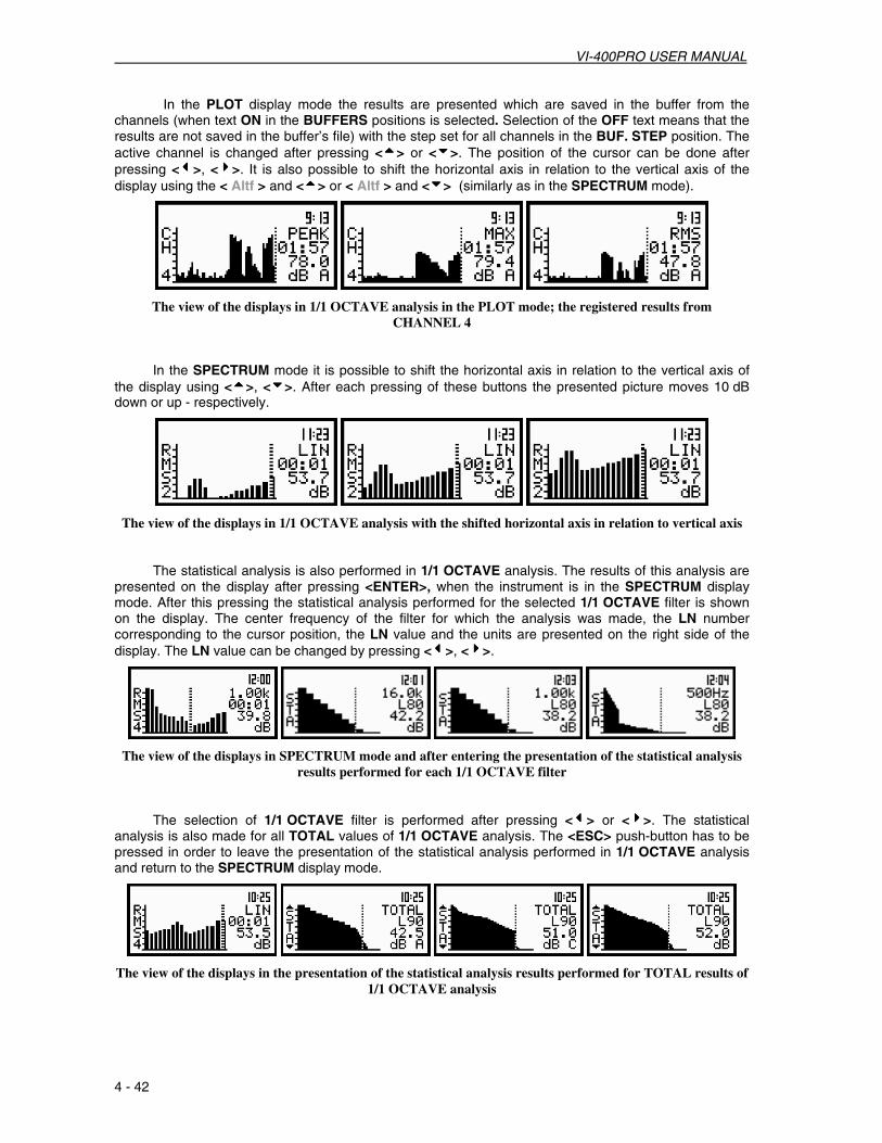
VI-400PRO USER MANUAL
4 - 42
In the PLOT display mode the results are presented which are saved in the buffer from the channels (when text ON in the BUFFERS positions is selected. Selection of the OFF text means that the results are not saved in the buffer’s file) with the step set for all channels in the BUF. STEP position. The active channel is changed after pressing <5555> or <6666>. The position of the cursor can be done after pressing <3333>, <4444>. It is also possible to shift the horizontal axis in relation to the vertical axis of the display using the < Altf > and <5555> or < Altf > and <6666> (similarly as in the SPECTRUM mode).
The view of the displays in 1/1 OCTAVE analysis in the PLOT mode; the registered results from CHANNEL 4
In the SPECTRUM mode it is possible to shift the horizontal axis in relation to the vertical axis of the display using <5555>, <6666>. After each pressing of these buttons the presented picture moves 10 dB down or up - respectively.
The view of the displays in 1/1 OCTAVE analysis with the shifted horizontal axis in relation to vertical axis
The statistical analysis is also performed in 1/1 OCTAVE analysis. The results of this analysis are presented on the display after pressing <ENTER>, when the instrument is in the SPECTRUM display mode. After this pressing the statistical analysis performed for the selected 1/1 OCTAVE filter is shown on the display. The center frequency of the filter for which the analysis was made, the LN number corresponding to the cursor position, the LN value and the units are presented on the right side of the display. The LN value can be changed by pressing <3333>, <4444>.
The view of the displays in SPECTRUM mode and after entering the presentation of the statistical analysis results performed for each 1/1 OCTAVE filter
The selection of 1/1 OCTAVE filter is performed after pressing <3333> or <4444>. The statistical analysis is also made for all TOTAL values of 1/1 OCTAVE analysis. The <ESC> push-button has to be pressed in order to leave the presentation of the statistical analysis performed in 1/1 OCTAVE analysis and return to the SPECTRUM display mode.
The view of the displays in the presentation of the statistical analysis results performed for TOTAL results of 1/1 OCTAVE analysis

VI-400PRO USER MANUAL
4 - 43
The spectra registered in the buffer’s file can be presented on the display in the BUFFER VIEW sub-list of the DISPLAY list (path: MENU / DISPLAY / BUFFER VIEW). These spectra are saved with the same step as selected in the SLM profiles (see the description of the BUF. STEP position of the MEASURE SETUP sub-list).
In order to display the file spectra registered in the buffer the user has to:
- press the <Alt f> and <4444> push-buttons for the spectra stored later; - press the < Alt f > and <3333> push-buttons for the spectra saved earlier.
In the BUFFER VIEW sub-list it is also possible to examine the time history for 1/1 OCTAVE filter selected by the cursor (see the description of the BUFFER VIEW sub-list in Chapter 5).
Notice: Many time histories can be saved in the buffer’s file of the instrument during the measurements performed in different sessions. The presentation of these results is possible using the BUFFER VIEW window of the DISPLAY list (path: MENU/ DISPLAY/ BUFFER VIEW) (see Chapter 5).
1/1 OCTAVE analysis can be performed taking into account the USER FILTERS coefficients set in the SETUP list (path: MENU/ SETUP/ USER FILTERS/ SOUND FILTERS (VIBR. FILTERS)/ VIEW (EDIT, CLEAR) (see Chapter 5 for detailed description of the USER FILTERS setting).
The view of the displays in the coefficient values setting of 1/3 or 1/1 OCTAVE filters in the USER FILTERS sub-list of the SETUP list
When these filters are switched on 1/1 OCTAVE analysis is performed in the normal way but simultaneously the USER FILTERS coefficients are taken into account for the calculation of the TOTAL result. The TOTAL results for the first, the second or for both USER FILTERS are presented instead of the TOTAL for A, C and LIN weighting filters.
The view of the displays in 1/1 OCTAVE analysis with the switched on USER FILTERS for CHANNEL 2
Selection of the measurement range in 1/1 OCTAVE analysis of acoustic signal - RANGE The selection of the input range is possible after entering the RANGE position (path: MENU /
INPUT / CHANNEL x / RANGE) (from the INPUT / CHANNEL x sub-list using <5555>, <6666> (or <3333>, <4444>) and pressing <ENTER>. The input ranges are specified in Appendix C. The return to the CHANNEL x sub-list is made, ignoring the changes, after pressing <ESC> or confirming the selection after pressing <ENTER>.

VI-400PRO USER MANUAL
4 - 44
The view of the displays with the RANGE (path: MENU / INPUT / CHANNEL x / RANGE) position selected
It is possible to change RANGE in SOUND mode. In this case the instrument operates in two input ranges 105dB or 130dB, which can be selected by means of the range position. In order to change the mode of the range the user has to press <3333>, <4444>.
The return to the CHANNEL x sub-list is made, ignoring the changes, after pressing <ESC> or confirming the selection after pressing <ENTER>.
The view of the displays with the RANGE (path: MENU / INPUT / CHANNEL x / RANGE) position selected for SOUND signal
Notice: It is not possible to change the range of the measurements during the execution of measurements. It is possible to open different lists and sub-lists but the positions in these lists are not high lighted and therefore not accessible. The “Loudspeaker” icon indicates that the instrument is in the measurement process. In order to change the range the measurement must be finished!
The view of the displays with RANGE position (path: MENU / INPUT / CHANNEL x / RANGE) not accessible.
Notice: If an OVERLOAD occurs it is signalled by the ”Bell” icon (see Chapter 3 for details).

VI-400PRO USER MANUAL
4 - 45
Selection of 1/1 OCTAVE analysis result of acoustic signal to be saved in the buffer’s file - BUFFERS SETUP
The measurements results from each channel can be saved in the buffer’s file of the instrument’s
SLM mode. The selection of the OFF option means that no result from the described channel have to be saved in the buffer’s file. The user can switch OFF or ON BUFFERS position by pressing <3333> or <4444>. After pressing <ENTER> any changes made in the sub-list are confirmed and the sub-list is closed. The return to the BUFFERS SETUP sub-list ignoring any changes made in the sub-list is made after pressing <ESC>.
The view of the displays in the BUFFERS SETUP sub-list (path: MENU / INPUT / BUFFERS SETUP); the selection of the BUFFERS store
The user can select the following results, which can be saved: PEAK, MAX, MIN and RMS in the
case of sound measurement. In order to switch parameters in the buffer, the user has to place the special character in the chosen position; available values are: [√√√√] or [ ]. The selection of the required buffers parameter is made with <3333>, <4444>. The user can pass to the selection of the next parameter from the CHANNEL x sub-list pressing <5555>, <6666>. After pressing <ENTER> any changes made in the sub-list are confirmed and the sub-list is closed. The return to the BUFFERS SETUP sub-list ignoring any changes made is made after pressing <ESC>.
The view of the displays in the CHANNEL 1 sub-list; the selection of the parameters to be saved in the buffer’s file
The view of the displays in the BUFFERS SETUP sub-list; the all the parameters were selected to be saved in the buffer’s file; in CHANNEL 1 and 2 vibration and in CHANNEL 3 and 4 sound parameters
Notice: The change of the channels parameters is not possible when the measurement is performed. The user has to finish the current measurement.
Notice: Setting BUFFER:OFF results in bypassing the storing of the given channel’s results in the buffer’s file. It creates more space in the buffer for other channels (see Chapter 5 for details).
Notice: The buffer is updated in the time periods (steps) defined in the BUF. STEP (path: MENU/ INPUT/ MEASURE SETUP/ BUF. STEP) The way the measurement results are stored is described in Chapter 5.

VI-400PRO USER MANUAL
4 - 46
Selection of 1/1 OCTAVE analysis parameters for acoustic signal – SPECTRUM
The SPECTRUM sub-list (path: MENU / INPUT / 1/1 OCTAVE SETUP / CHANNEL x / SPECTRUM) is a context element, which appears on the INPUT sub-list in 1/1 OCTAVE or 1/3 OCTAVE mode. Using the SPECTRUM sub-list one can select in 1/1 OCTAVE analysis the weighting filter and the result which are to be saved in the buffer’s file of the instrument. The user can select it for each CHANNEL separately.
The user can switch OFF or ON SPECTRUM position in selected channels by pressing <3333> or <4444>. After pressing <ENTER> any changes made in the sub-list are confirmed and the sub-list is closed. The return to the INPUT sub-list ignoring any changes made in the sub-list is made after pressing <ESC>.
The view of the displays in the INPUT sub-list (path: MENU / INPUT / 1/1 OCTAVE SETUP / CHANNEL x /
SPECTRUM) with the SPECTRUM sub-list in 1/1 OCTAVE analyzer
Selection of the weighting filter in 1/1 OCTAVE analysis of acoustic signal - FILTER
The following weighting filters are available in 1/1 OCTAVE analysis:
• A type 1 according to the IEC 651 and IEC 61672-1 standards, • C type 1 according to the IEC 651 and IEC 61672-1 standards, • LIN conforms to the requirements for the Z filter of type 1 according to the IEC 61672-1 standard, • HP high-pass filter for 1/1 OCTAVE analysis.
The view of the displays with the SPECTRUM sub-list (path: MENU/ INPUT/ 1/1 OCTAVE SETUP/ CHANNEL x/ SPECTRUM) opened, the selection of the weighting filter
The characteristics of the filters are given in Appendix D. The selection of the required filter is
made with <3333>, <4444>. After pressing <ENTER> any changes made in the sub-list are confirmed and the sub-list is closed. The return to the 1/1 OCTAVE SETUP sub-list ignoring any changes is made after pressing <ESC>.
Notice: It is not possible to change the values of the parameters during the execution of the measurements. It is possible to open different lists and sub-lists but the positions in these lists are not high lighted and therefore not accessible. The “Loudspeaker” icon indicates that the instrument is in the measurement process. In order to change the range the measurement must be finished!
The view of the displays with not accessible parameters of the PROFILES SETUP lists

VI-400PRO USER MANUAL
4 - 47
Selection of 1/1 OCTAVE analysis result to be saved in the buffer’s file - BUFFER position
The RMS or LEQ (when the user selects A filter in FILTER position in SPECTRUM sub-list) result from 1/3 OCTAVE analysis can be saved in the buffer’s file of the instrument. The selection of the required result is made with <3333>, <4444>. The selection of the None text means that the RMS or LEQ results are not saved in the buffer’s file. After pressing <ENTER> any changes made in the sub-list are confirmed and the sub-list is closed returning to the 1/3 OCTAVE SETUP/ CHANNEL x sub-list. Pressing <ESC> ignores and changes made in the sub-list and returns to the 1/3 OCTAVE SETUP/ CHANNEL x sub-list.
The view of the displays in the SPECTRUM sub-list (path: MENU / INPUT / PROFILES SETUP / 1/1 OCTAVE SETUP / CHANNEL x / SPECTRUM), the selection of the BUFFER position
Notice: It is not possible to change the values of the parameters during the execution of the measurements. It is possible to open different lists and sub-lists but the positions in these lists are not high lighted and therefore not accessible. The “Loudspeaker” icon indicates that the instrument is in the measurement process. In order to change the range the measurement must be finished!
The view of the displays with not accessible parameters of the PROFILES SETUP lists (path: MENU / INPUT /
1/1 OCTAVE SETUP),
Notice: All other settings of the instrument are common for 1/3 OCTAVE analyzer and the SLM.
Selection of the result which triggers registration in BUFFER mode in 1/1 OCTAVE analysis of acoustic signal
In level meter mode only the result coming from the MAX detector of the one channel is used for triggering purposes. In the case of vibration measurements it is VECT, VEC/SND or MAX value. The SOURCE position is not accessible in that mode. However, in 1/1 OCTAVE analysis it is possible to access the above mentioned position and to make a selection. The results coming from the output of 1/1 OCTAVE filters, starting from 125 Hz (125 Hz, 250 Hz, 500 Hz, 1.00 kHz, 2.00 kHz, 4.00 kHz, 8.00 kHz and 16.0 kHz), are available as well as MAX result from the selected channel.

VI-400PRO USER MANUAL
4 - 48
The view of the displays in TRIGGER SETUP window; the selection of the signal used for triggering purposes in BUFFER mode
Notice: It is not possible to change the values of the parameters during the execution of the measurements. It is possible to open different lists and sub-lists but the positions in these lists are not high lighted abd therefore not accessible. The “Loudspeaker” icon indicates that the instrument is in the measurement process. In order to change the range the measurement must be finished!
Notice: All other settings of the instrument are common for 1/1 OCTAVE analyzer and the SLM.

VI-400PRO USER MANUAL
4 - 49
4.4.2. 1/1 OCTAVE analyzer of vibration signal
In order to select the instrument’s vibration mode the user has to enter the CHANNELS SETUP list by pressing <MENU>, selecting the INPUT text using <5555>, <6666> (or <3333>, <4444>) and pressing the <ENTER>, and then enter the CHANNELS SETUP by chose the number of the CHANNEL to configure. In the MODE sub-list the user can select the kind of input signal which has to be measured or analysed by the instrument. In the case of vibartion signals the VIBRATION METER option should be selected by pressing <3333>, <4444> to change to VIBR. mode and press <ENTER> which accepts the change and closes the MODE sub-list. The MODE sub-list is closed, ignoring any changes made, after pressing <ESC>.
a) b) c)
The view of the displays in the CHANNEL x (path: MENU / INPUT) list with the CHANNEL x text selected (a); the SOUND METER mode selected (b) and the VIBR. METER mode selected (c)
In 1/1 OCTAVE analysis the spectrum is available in parallel to the VLM operation. All 15 digital band-pass filters (with the center frequencies from 16 kHz down to 1 Hz; in base-two system) are working in the real time with the linear RMS Detector displayed in the SPECTRUM sub-list of the 1/3 OCTAVE SETUP. In order to inform the user about the working mode of the instrument, in One profile and 3 PROFILES display modes doted lines are used for the indication that the instrument is not in VLM mode. In the VLM mode continuous lines are used.
The view of the displays in One profile and 3 PROFILES display mode with the doted lines indicating that the instrument is not in the VLM mode
Note: The TOTAL RMS result is measured with the HP weighting filter and takes no account of the VLM profile settings. The spectra are always linearly averaged. Thus, the TOTAL value from 1/1 OCTAVE analysis can differ from those obtained in the VLM profiles (if the RMS INTEGRATION is set to EXPONENTIAL).
In order to change the display mode the user has to press <5555> or <6666> . The following modes are available:
One profile, 3 PROFILES, SPECTRUM and PLOT.
Notice: The user can select the number of the currently active display modes switching on ([√√√√]) or off ([ ]) the given mode in the DISPLAY MODES sub-list of the DISPLAY list. Only One profile mode cannot be switched off. See Chapter 5 for the details about the display modes control.

VI-400PRO USER MANUAL
4 - 50
One Profile, 3 PROFILES and PLOT display modes are identical as for the VLM. The SPECTRUM mode displays 1/1 OCTAVE analysis results (so-called spectrum) together with the TOTAL RMS value measured with the HP weighting filter and the TOTAL values measured for filters, which are set in the TOTAL VALUES sub-list of the DISPLAY SETUP list (path: MENU / DISPLAY / DISPLAY SETUP / CHANNEL x / TOTAL VALUES).
The displays with the settings influencing the first TOTAL value presented in the SPECTRUM mode The first TOTAL value is measured with:
• the HP weighting filter (in this case it is true RMS value in the whole band) or • with the filter specified as VUSR1, VUSR2, VUSR3 or • Any other filter, which name and the coefficients are sent to the unit by the serial interface.
The coefficients of the user defined filters are set in the VIBR. FILTERS sub-list of the SETUP list (path: MENU / SETUP / USER FILTERS / VIBR. FILTERS). It is also possible to send the coefficients of the filters used in the calculations by means of the serial interface from a PC (a special function is developed for this purpose – contact Quest Technologies for a list of available Remote Commands for the VI-400Pro). The names of the filters introduced to the unit in above mentioned way, as well as the values of the coefficients, can be examined by means of the VIEW window from the VIBR. FILTERS sub-list of the SETUP list (path: MENU / SETUP / USER FILTERS / VIBR. FILTERS / VIEW).
The displays showing the possibility of the verification of the user filter names and the values of the coefficients taken to the calculation of the TOTAL values presented in the SPECTRUM mode
The second TOTAL value is measured with the weighting filter: • selected in the second channel (CH) or • specified as VUSR1, VUSR2, VUSR3 or • which name and coefficients are sent to the instrument using the serial interface (a list of Remote
Commands for this function is available from Quest Technologies).

VI-400PRO USER MANUAL
4 - 51
The view of the displays with the settings influencing the TOTAL values presented in the SPECTRUM mode in selected CHANNEL
The third TOTAL value is measured with the weighting filter:
• selected in the third channel (CH) or • specified as VUSR1, VUSR2, VUSR3 or • which name and coefficients are sent to the instrument using the serial interface (a list of Remote
Commands for this function is available from Quest Technologies).
The view of the displays with the settings influencing the TOTAL values presented in the SPECTRUM mode The results of 1/1 OCTAVE analysis, so-called spectrum, can be presented as the acceleration,
velocity or displacement spectrum. The type of the spectrum is selected in the SPECTRUM TYPE window of the DISPLAY SETUP sub-list (path: MENU / DISPLAY / DISPLAY SETUP / CHANNEL x / SPECTRUM TYPE / ACCELERATION, VELOCITY or DISPLACEMENT).
The view of the displays with the settings influencing 1/1 OCTAVE analysis results presentation in the SPECTRUM mode
The results of 1/1 OCTAVE analysis are always calculated and saved as the acceleration
spectrum. The ACC text given in the first left column indicates that the acceleration spectrum is presented on the display.
In order to present the velocity spectrum the linear accelerometer value from each 1/1 OCTAVE filter is divided by 2ππππfc, where fc is the exact central frequency of the mentioned filter. The VEL text is presented in the first column of the display in this case indicating the type of the spectrum.
In order to present the displacement spectrum the linear velocity value from each 1/1 OCTAVE filter is divided by 2ππππfc, where fc is the exact central frequency of the mentioned filter. The DIL text is given in the first column of the display in this case indicating the type of the spectrum.
The view of the displays in 1/1 OCTAVE analysis in the SPECTRUM display mode, LINear (path: MENU / DISPLAY / DISPLAY SETUP / CHANNEL x / DISPLAY SCALE / LIN) vibration scale, METRIC (path: MENU / SETUP /
VIBRATION UNITS / METRIC) units settings selected

VI-400PRO USER MANUAL
4 - 52
The read-out of the interested spectrum value can be done by means of the cursor controlled by <3333>, <4444>. On the right side of the display the selected 1/1 octave filter center frequency (or the selected TOTAL) is given, the current time of registered spectrum, the numerical value corresponding to the position of the cursor and the units are displayed in the consecutive lines.
Note: The displayed units during the measurement or analysis of vibration signal depends on the different settings made in the VIBRATION UNITS (METRIC or NON-METRIC), the SCALE position of DISPLAY SCALE (LINear or LOGarithmic) and the weighting FILTER set in CHANNELS x (for acceleration, velocity or displacement measurements).
…
…
The view of the displays with different settings influencing the units of vibration results
In One profile and 3 PROFILES modes the results are presented in the same way as in VLM mode with the only difference that doted lines are used instead of solid lines. The active channel is changed after each pressing of <Atlf> and <5555> or < Atlf > and <6666>. The change of the result from the same channel is done by pressing <3333>, <4444>.
The view of the displays in 1/1 OCTAVE analysis in One profile and 3 PROFILES display modes
In the PLOT mode the results are presented which are saved in the buffer with the step set for all channels in the BUF. STEP position. The active channel is changed after pressing <5555> and <6666>. The position of the cursor can be done after pressing <3333>, <4444>. It is also possible to shift the horizontal axis in relation to the vertical axis of the presented results using < Atlf > and <5555> or < Atlf > and <6666> (similarly as it is done in the SPECTRUM mode).
The view of the displays in 1/1 OCTAVE analysis in the PLOT mode; the registered results from all profiles

VI-400PRO USER MANUAL
4 - 53
In the SPECTRUM mode it is possible to shift the horizontal axis in relation to the vertical axis of the presented results using < Atlf > and <5555> or < Atlf > and <6666>. After each pressing of these buttons the presented picture moves 10 dB down or up, respectively.
The view of the displays in 1/1 OCTAVE analysis with the shifted horizontal axis in relation to vertical axis
The spectra registered in the buffer’s file can be presented on the display in the BUFFER VIEW sub-list of the DISPLAY list (path: MENU / DISPLAY / BUFFER VIEW). These spectra are saved with the same step as selected in the SLM profiles (see the description of the BUF. STEP position of the MEASURE SETUP sub-list).
In order to display the spectra registered in the buffer’s file the user has to:
- press <4444> for the spectra stored later; - press <3333> for the spectra saved earlier.
In the BUFFER VIEW sub-list it is also possible to examine the time history for 1/1 OCTAVE filter selected by the cursor (see the description of the BUFFER VIEW sub-list in Chapter 5).
Notice: Many time histories can be saved in the buffer’s file of the instrument during the measurements performed in different sessions. The presentation of these results is possible using the BUFFER VIEW window of the DISPLAY list (see Chapter 5).
Measurement range selection in 1/1 OCTAVE analysis of vibration signal - RANGE The selection of the input range is possible after entering the RANGE position (path: MENU / INPUT/
CHANNEL x/ RANGE) (from the INPUT/ CHANNEL x list using <5555>, <6666> (or <3333>, <4444>) and pressing <ENTER>. The input ranges are specified in Appendix C. The return to the CHANNEL x list, ignoring the changes, is made after pressing <ESC> or confirming the selection after pressing <ENTER>.
The view of the displays with the RANGE (path: MENU / INPUT / CHANNEL x / RANGE) position selected
It is possible to change RANGE in VIBRATION mode. In this case the instrument operates in two input ranges 117.8 m/s2 or 316 m/s2, which can be selected by means of the range position. In order to change the mode of the range the user has to press <3333>, <4444>.
The return to the CHANNEL x list, ignoring the changes, is made after pressing <ESC> or confirming the selection after pressing <ENTER>.

VI-400PRO USER MANUAL
4 - 54
The view of the displays with the RANGE (path: MENU / INPUT / CHANNEL x / RANGE) position selected in case of VIBRATION signal
Notice: It is not possible to change the range of the measurements during the execution of the measurements. It is possible to open different lists and sub-lists but the positions in these lists are not high lighted and therefore not accessible. The “Loudspeaker” icon indicates that the instrument is in the measurement process. In order to change the range the measurement must be finished!
The view of the displays with RANGE position (path: MENU / INPUT / CHANNEL x / RANGE) not accessible.
Notice: If an OVERLOAD occurs it is signalled by the ”Bell” icon (see Chapter 3 for details).
Selection of 1/1 OCTAVE analysis result of vibration signal to be saved in the buffer’s file - BUFFES SETUP
The measurements results from each channel can be saved in the buffer’s file of the instrument’s VLM mode. The selection of the OFF option means that no result from the described channel have to be saved in the buffer’s file. User can switch OFF or ON BUFFERS position by pressing <3333> or <4444>. After pressing <ENTER> any changes made in the sub-list are confirmed and the sub-list is closed. The return to the BUFFERS SETUP sub-list ignoring any changes made in the sub-list is made after pressing <ESC>.
The view of the displays in the BUFFERS SETUP sub-list list (path: MENU / INPUT / BUFFERS SETUP); the selection of the BUFFERS store
The user can select the following results, which can be saved: PEAK, P–P, MAX and RMS in the case of vibration measurement. The selection of the parameter from the CHANNEL x sub-list is made by pressing <5555>, <6666>. After pressing <ENTER> any changes made in the sub-list are confirmed and the sub-list is closed. The return to the BUFFERS SETUP sub-list ignoring any changes made in the sub-list is made after pressing <ESC>.

VI-400PRO USER MANUAL
4 - 55
In order to switch parameters in the buffer, the user has to place special character in the chosen position; available values are: [√√√√] or [ ]. The selection of the required buffers parameter is made with <3333>, <4444>. The user can pass to the selection of the next parameter in the CHANNEL x sub-list pressing <5555>, <6666>. After pressing <ENTER> any changes made in the sub-list are confirmed and the sub-list is closed. Pressing <ESC> returns to the BUFFERS SETUP sub-list ignoring any changes made in the sub-list.
The view of the displays in the CHANNEL 1 sub-list; the selection of the parameters to be saved in the buffer’s file
The view of the displays in the BUFFERS SETUP sub-list; the all the parameters were selected to be saved in the buffer’s file; in CHANNEL 1 and 2 vibration and in CHANNEL 3 and 4 sound parameters
Notice: The change of the channels parameters is not possible while the measurement is performed. The user has to finish the current measurement.
Notice: Setting BUFFER:OFF results in bypassing the storing of the given channel’s results in the buffer’s file. It creates more space in the buffer for other channels (see Chapter 5 for details).
Notice: The buffer is updated in the time periods (steps) defined in the BUF. STEP (path: MENU / INPUT / MEASURE SETUP / BUF. STEP). The way the measurement results are stored is described in Chapter 5.
Selection of 1/1 OCTAVE analysis parameters for vibration signal - SPECTRUM
The SPECTRUM sub-list (path: MENU / INPUT / 1/1 OCTAVE SETUP / CHANNEL x / SPECTRUM) is
a context element, which appears on the INPUT sub-list in 1/1 OCTAVE or 1/3 OCTAVE mode. Using the SPECTRUM sub-list one can select in 1/1 OCTAVE analysis the result which has to be saved in the buffer’s file of the instrument.
The view of the displays in the 1/1 OCTAVE SETUP window with the SPECTRUM text
selected in CHANNEL x position

VI-400PRO USER MANUAL
4 - 56
User can switch OFF or ON SPECTRUM position in selected channels by pressing <3333> or <4444>.
After pressing <ENTER> any changes made in the sub-list are confirmed and the sub-list is closed. Pressing <ESC> returns to the INPUT sub-list ignoring any changes made in the sub-list.
Selection of 1/1 OCTAVE analysis result of vibration signal to be saved in the buffer’s file - BUFFER
The RMS result from 1/1 OCTAVE analysis can be saved in the buffer’s file of the instrument. The selection of the required result is made with the <3333>, <4444> push-buttons. The selection of the None text means that the RMS results are not saved in the buffer’s file. The user causes the return to the 1/1 OCTAVE SETUP/ CHANNEL x sub-list pressing the <ENTER> push-button with the confirmation of the selections made in the sub-list. The return to the 1/1 OCTAVE SETUP/ CHANNEL x sub-list is also possible after pressing the <ESC> push-button but all changes are in this case ignored.
The view of the displays in the SPECTRUM sub-list (path: MENU / INPUT / PROFILES SETUP / 1/1 OCTAVE SETUP / CHANNEL x / SPECTRUM), the selection of the BUFFER position
Notice: It is not possible to change the values of the parameters during the execution of the measurements. It is possible to open different lists and sub-lists but the positions in these lists are not high lighted and therefore not accessible. The “Loudspeaker” icon indicates that the instrument is in the measurement process. In order to change the range the measurement must be finished!
The view of the displays with not accessible parameters of the 1/1 OCTAVE SETUP lists (path: MENU / INPUT/ 1/1 OCTAVE SETUP),
Notice: All other settings of the instrument are common for 1/1 OCTAVE analyzer and the VLM.
Selection of the result which triggers registration in BUFFER mode in 1/1 OCTAVE analysis of vibration signal
In level meter mode only the result coming from the RMS detector of channel one is used for triggering purposes. In the case of vibration measurements it is VECTOR, VEC/SND or RMS value. The SOURCE position is not accessible in that mode. However, in 1/1 OCTAVE analysis it is possible to access the above mentioned position and to make a selection. The results coming from the output of 1/1 OCTAVE filters, starting from 125 Hz (125 Hz, 250 Hz, 500 Hz, 1.00 kHz, 2.00 kHz, 4.00 kHz, 8.00 kHz and 16.0 kHz), are available as well as RMS result from the selected channel.
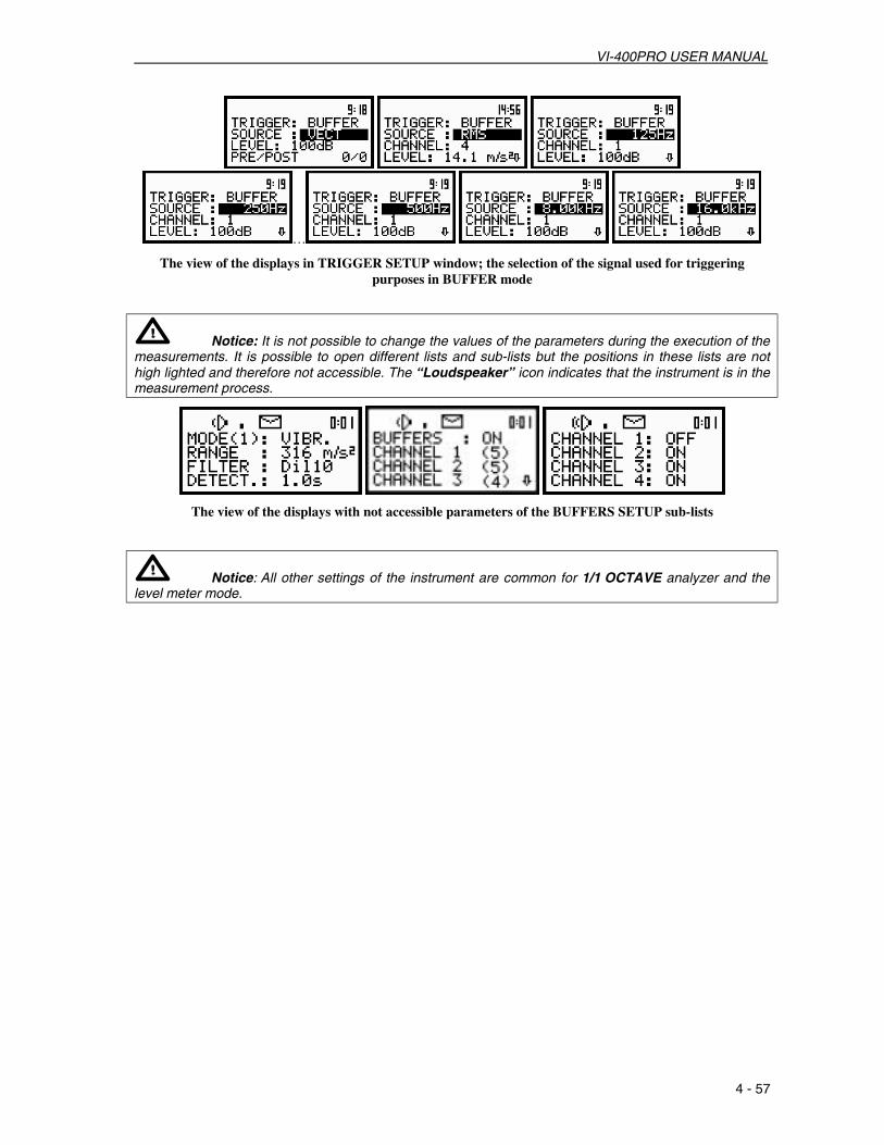
VI-400PRO USER MANUAL
4 - 57
…
The view of the displays in TRIGGER SETUP window; the selection of the signal used for triggering purposes in BUFFER mode
Notice: It is not possible to change the values of the parameters during the execution of the measurements. It is possible to open different lists and sub-lists but the positions in these lists are not high lighted and therefore not accessible. The “Loudspeaker” icon indicates that the instrument is in the measurement process.
The view of the displays with not accessible parameters of the BUFFERS SETUP sub-lists
Notice: All other settings of the instrument are common for 1/1 OCTAVE analyzer and the level meter mode.

VI-400PRO USER MANUAL
4 - 58
4.5. 1/3 OCTAVE ANALYZER
In order to select the 1/3 OCTAVE analysis mode the user has to enter the FUNCTION list by pressing <Alt f> and <MENU>, selecting FUNCTION text using <5555>, <6666> (or <3333>, <4444>) and pressing <ENTER>. Then, the user has to open the MEASUR. FUNCTION sub-list (to select the MEASUR. FUNCTION text use <3333>, <4444> (or <3333>, <4444>) push-buttons and press <ENTER> when this text is high lighed).
a) b) c)
The view of the displays in the main list with the FUNCTION text selected (a), the FUNCTION list (path: MENU / FUNCTION) opened with the MEASUR. FUNCTION text selected (b), 1/3 OCTAVE analysis mode
selected in MEASUR. FUNCTION sub-list (c)
1/3 OCTAVE mode is selected by placing the special character in the line with 1/3 OCTAVE text. The position of the character can be changed using <5555>, <6666> (or <3333>, <4444>). After placing the character in the line with 1/3 OCTAVE text the user has to press <ENTER>, which closes the MEASUR. FUNCTION sub-list and confirms the selection. After pressing <ESC> the sub-list is also closed but any changes are ignored.
Notice: It is not possible to change the mode during the measurements. The instrument displays in this case for about 3 seconds the text: “measurement in progress / MEASUREMENT IN PROGRESS”. In order to change the mode the measurement must be finished!
The view of the displays with the text informing the user about the currently performed measurements

VI-400PRO USER MANUAL
4 - 59
4.5.1. 1/3 OCTAVE analyzer of acoustic signal
In order to select the instrument’s acoustic mode the user has to enter the CHANNELS SETUP list by pressing <Altf> and <MENU>, selecting the INPUT text using <5555>, <6666> (or <3333>, <4444>) and pressing <ENTER>, and then enter the CHANNELS SETUP in similar fashion and chose the number of CHANNEL to configuration. In the MODE sub-list the user can select the kind of input signal which has to be measured or analysed by the instrument. In the case of acoustic signals the SOUND METER option should be selected by pressing <3333>, <4444> to change to SOUND and press <ENTER>, which closes the MODE sub-list. The MODE sub-list is closed ignoring any changes made in it, after pressing <ESC>.
a) b) c)
The view of the displays in the CHANNEL x (path: MENU / INPUT) list with the CHANNEL x text selected (a); the VIBR. METER mode selected (b) and the SOUND METER mode selected (c)
The instrument’s operation as 1/3 OCTAVE analyzer is similar to the SLM measurement mode.
1. In 1/3 OCTAVE analysis the spectrum is available in parallel to the SLM operation. All 45 digital pass-band filters (with the center frequencies from 20 kHz down to 0.8 Hz; in base two system) are working in the real time with the weighting filters: HP, LIN, A or C selected in the SPECTRUM of the 1/3 OCTAVE SETUP sub-list, the user has to select the number of CHANNEL to configure the filter, and the linear RMS detector. Additionally, the TOTAL RMS values for the full frequency range with the A, C and LIN (Z) weightings are displayed. In order to inform the user about the working mode of the instrument, in One profile and 3 PROFILES display modes doted lines are used for the indication that the instrument is not in the SLM mode. In the SLM mode solid lines are used.
The view of the displays in One profile and 3 PROFILES display mode with the doted lines indicating that the instrument is not in the SLM mode
Notice: The TOTAL RMS results are measured with the weighting filters: A, C and LIN without taking into account the setting of the SLM profiles. The spectra are always linearly averaged. Thus, the TOTAL values from 1/3 OCTAVE analysis can be different from those obtained for the SLM profiles (if the RMS INTEGRATION (path: MENU/ SETUP/ RMS INTEGRATION) was set as EXPONENTIAL).
2. As 1/3 OCTAVE analyzer the instrument operates in two input ranges 105 dB and 130 dB, which can be selected by means of the RANGE position.
In order to change the mode of the display presentation the user has to press <5555> or <6666>. The following modes are available:
One profile, SPECTRUM, 3 PROFILES, STATISTICS and PLOT.

VI-400PRO USER MANUAL
4 - 60
Notice: The user can select the number of the currently active display modes switching on ([√√√√]) or off ([ ]) the given mode in the DISPLAY sub-list of the DISPLAY list. Only one profile mode cannot be switched off. See Chapter 5 for the details about the display modes control.
One Profile, 3 PROFILES, STATISTICS and PLOT display modes are identical as for the SLM. The SPECTRUM mode displays 1/3 OCTAVE analysis results (so-called spectrum) together with the TOTAL RMS values measured with A, C and LIN weighting filters. The read-out of the interested spectrum value can be done by means of the cursor controlled by <3333>, <4444>. On the right side of the display the selected 1/3 octave filter center frequency (or the selected TOTAL) is given, the units with the weighting filter (dB A, dB C or dB in the case of the LIN) and the numerical value are displayed.
The view of the displays in 1/3 OCTAVE analysis in the SPECTRUM display mode for CHANNEL 1
In One profile and 3 PROFILES display modes are presented in the same way as in the case of the SLM mode with only one difference that instead of the solid line the doted line is used. The active channel is changed after each pressing of <5555>, <6666>. The change of the result from the same channel is done by pressing <3333>, <4444> push-buttons. The LN value is changed after pressing <Altf> and <3333> or < Altf > and <4444> push-buttons.
The view of the displays in 1/3 OCTAVE analysis in One profile and 3 PROFILES display modes
In the STATISTICS mode it is possible to select the LN value using <3333>, <4444>. The active channel is presented on the left side of the display. LN corresponding to the current position of the cursor is displayed in the second line of the right sight of the display, value of LN - in the third line and the units together with the indicator of the weighting filter - in the fourth. When the STATISTICS mode of result’s presentation is entered (<Altf > and <5555> or < Altf > and <6666> are used for this purpose) in order to change the active channel <5555>, <6666> should be pressed.
The view of the displays in 1/3 OCTAVE analysis with presentation of the statistical analysis in all channels In the PLOT mode the results are presented which are saved in the buffer from the channels (in
case when text ON in the BUFFERS positions is selected) and user selects in the CHANNEL x sub-lists position to display in PLOT mode (user can switched on ([√√√√] selected position to display in PLOT mode) with the step set for all channels in the BUF. STEP position. The active channel is changed after pressing <5555> and <6666>. The position of the cursor can be done after pressing <3333>, <4444>. It is also possible to shift the horizontal axis in relation to the vertical axis of the presented results using the < Altf > and <5555> or < Altf > and <6666> (similarly as in the SPECTRUM mode).

VI-400PRO USER MANUAL
4 - 61
The view of the displays in 1/3 OCTAVE analysis in the PLOT mode; the registered results from all channels
In the SPECTRUM mode it is possible to shift the horizontal axis in relation to the vertical axis of the presented results using the < Altf > and <5555> or < Altf > and <6666> push-buttons. After each pressing of these buttons the presented picture moves 10 dB down or up - respectively.
The view of the displays in 1/3 OCTAVE analysis with the shifted horizontal axis in relation to vertical one
The statistical analysis is also performed in 1/3 OCTAVE analysis. The results of this analysis are presented on the display after pressing <ENTER> in the case when the instrument is in the SPECTRUM display mode. After this pressing the statistical analysis performed for the selected 1/3 OCTAVE filter is shown on the display. The center frequency of the filter for which the analysis was made, the LN number corresponding to the cursor position, the LN value and the units are presented on the right side of the display. The LN value can be changed by pressing <3333>, <4444>.
The view of the displays in SPECTRUM mode and after entering the presentation of the statistical analysis results performed for each 1/3 OCTAVE filter
The selection of 1/3 OCTAVE filter is performed after pressing <3333> or <4444>. The statistical analysis is also made for all TOTAL values of 1/3 OCTAVE analysis. <ESC> has to be pressed in order to leave the presentation of the statistical analysis performed in 1/3 OCTAVE analysis and return to the SPECTRUM display mode.
The view of the displays in the presentation of the statistical analysis results performed for TOTAL results of 1/3 OCTAVE analysis
The spectra registered in the buffer’s file can be presented on the display in the BUFFER VIEW
sub-list of the DISPLAY list path: MENU / DISPLAY / BUFFER VIEW). These spectra are saved with the same step as selected in the SLM profiles (see the description of the BUF. STEP position of the MEASURE SETUP sub-list).
In order to display the spectra registered in the buffer’s file the user has to:
- press <4444> for the spectra stored later; - press <3333> for the spectra saved earlier.

VI-400PRO USER MANUAL
4 - 62
In the BUFFER VIEW sub-list it is also possible to examine the time history for 1/3 OCTAVE filter selected by the cursor (see the description of the BUFFER VIEW sub-list in Chapter 5).
Notice: Many time histories can be saved in the buffer’s file of the instrument during the measurements performed in different sessions. The presentation of these results is possible using the BUFFER VIEW window of the DISPLAY list (see Chapt.5).
1/3 OCTAVE analysis can be performed taking into account the USER FILTERS coefficients set in the SETUP list (see Chapter 5 for detailed description of the USER FILTERS setting).
The view of the displays in the coefficient values setting of 1/3 or 1/1 OCTAVE filters in the USER FILTERS sub-list of the SETUP list
When these filters are switched on 1/3 OCTAVE analysis is performed in the normal way but simultaneously the USER FILTERS coefficients are taken into account for the calculation of the TOTAL result. The TOTAL results for the first, the second or for both USER FILTERS are presented instead of the TOTAL for A, C and LIN weighting filters.
The view of the displays in 1/3 OCTAVE analysis with the switched on USER FILTERS for CHANNEL x
Selection of the measurement range in 1/3 OCTAVE analysis of acoustic signal - RANGE The selection of the input range is possible after entering the RANGE position (path: MENU /
INPUT / CHANNEL x / RANGE) (from the INPUT/ CHANNEL x list using <5555>, <6666> (or <3333>, <4444>) and pressing <ENTER>. The input ranges specified in Appendix C. The return to the CHANNEL x list is made ignoring the changes after pressing <ESC> or confirming the selection after pressing <ENTER>.
The view of the displays with the RANGE (path: MENU / INPUT / CHANNEL x / RANGE) position selected

VI-400PRO USER MANUAL
4 - 63
It is possible to change RANGE in SOUND mode. In this case the instrument operates in two input ranges 105dB and 130dB, which can be selected by means of the range position. In order to change the mode of the range the user has to press <3333>, <4444>.
The return to the CHANNEL x list ignoring the changes is made after pressing <ESC> or confirming the selection after pressing <ENTER>.
The view of the displays with the RANGE (path: MENU / INPUT / CHANNEL x / RANGE) position selected in the case of SOUND signal
Notice: It is not possible to change the range of the measurements during the execution of the measurements. It is possible to open different lists and sub-lists but the positions in these lists are not high lighted and therefore not accessible. The “Loudspeaker” icon indicates that the instrument is in the measurement process. In order to change the range the measurement must be finished!
The view of the displays with RANGE position (path: MENU / INPUT / CHANNEL x / RANGE) not accessible.
Notice: If an OVERLOAD occurs it is signalled by the ”Bell” icon (see Chapter 3 for details).
Selection of 1/3 OCTAVE analysis result of acoustic signal to be saved in the buffer’s file - BUFFERS SETUP
The measurements results from each channel can be saved in the buffer’s file of the instrument’s SLM mode. The selection of the OFF option means that no result from the described channel have to be saved in the buffer’s file. User can switch OFF or ON BUFFERS position by pressing <3333> or <4444>. After pressing <ENTER> any changes made in the sub-list are confirmed and the sub-list is closed. Pressing <ESC> also returns to the BUFFERS SETUP sub-list ignoring any changes made in the sub-list.
The view of the displays in the BUFFERS SETUP sub-list (path: MENU / INPUT / BUFFERS SETUP), the selection of the BUFFER position

VI-400PRO USER MANUAL
4 - 64
The user can select the following results, which can be saved: PEAK, MAX, MIN and RMS in the case of sound measurement. The selection of the parameter from the CHANNEL x sub-list is made by pressing <5555>, <6666>. After pressing <ENTER> any changes made in the sub-list are confirmed and the sub-list is closed. Pressing <ESC> also returns to the BUFFERS SETUP sub-list ignoring any changes made in the sub-list.
In order to switch parameters in the buffer, the user has to place the special character in the chosen position; available values are: [√√√√] or [ ]. The selection of the required buffers parameter is made with <3333>, <4444>. The user can pass to the selection of the next parameter from the CHANNEL x sub-list pressing <5555>, <6666>. After pressing the <ENTER> push-button any changes made in the sub-list are confirmed and the sub-list is closed. Pressing <ESC> also returns to the BUFFERS SETUP sub-list ignoring any changes made in the sub-list.
The view of the displays in the CHANNEL 1 sub-list; the selection of the parameters to be saved in the buffer’s file
The view of the displays in the BUFFERS SETUP sub-list; the all the parameters were selected to be saved in the buffer’s file; in CHANNEL 1 and 2 vibration and in CHANNEL 3 and 4 sound parameters
Notice: The change of the channels parameters is not possible when the measurement is performed. The user has to finish the current measurement.
Notice: Setting BUFFER:OFF results in bypassing the storing of the given channel’s results in the buffer’s file. It creates more space in the buffer for other channels (see Chapter 5 for details).
Notice: The buffer is updated in the time periods (steps) defined in the BUF. STEP (path: MENU/ INPUT/ MEASURE SETUP/ BUF. STEP). The way the measurement results are stored is described in Chapter 5.
Notice: It is not possible to change the values of the parameters during the execution of the measurements. It is possible to open different lists and sub-lists but the positions in these lists are not high lighted and therefore not accessible. The “Loudspeaker” icon indicates that the instrument is in the measurement process. In order to change the range the measurement must be finished!

VI-400PRO USER MANUAL
4 - 65
The view of the displays with not accessible parameters of the BUFFERS SETUP lists (path: MENU / INPUT / BUFFERS SETUP),
Notice: All other settings of the instrument are common for 1/3 OCTAVE analyzer and the SLM.
Selection of 1/3 OCTAVE analysis parameters for acoustic signal - SPECTRUM
The SPECTRUM sub-list (path: MENU / INPUT / 1/3 OCTAVE SETUP / CHANNEL x / SPECTRUM) is a context element, which appears on the INPUT sub-list in 1/1 OCTAVE or 1/3 OCTAVE mode. Using the SPECTRUM sub-list one can select in 1/3 OCTAVE analysis the weighting filter and the result which has to be saved in the buffer’s file of the instrument. The user can select it for every CHANNEL separately.
User can switch OFF or ON SPECTRUM position in selected channels by pressing <3333> or <4444>. After pressing <ENTER> any changes made in the sub-list are confirmed and the sub-list is closed. Pressing <ESC> also returns to the INPUT sub-list ignoring any changes made in the sub-list.
The view of the displays in the INPUT sub-list (path: MENU / INPUT / 1/3 OCTAVE SETUP / CHANNEL x /
SPECTRUM) with the SPECTRUM sub-list in 1/1 OCTAVE analyzer
The view of the displays in the 1/3 OCTAVE SETUP sub-list with the SPECTRUM sub-list
Selection of the weighting filter in 1/3 OCTAVE analysis of acoustic signal - FILTER position
The following weighting filters are available in 1/3 OCTAVE analysis: • A type 1 according to the IEC 651 and IEC 61672-1 standards, • C type 1 according to the IEC 651 and IEC 61672-1 standards, • LIN conforms to the requirements for the Z filter of type 1 according to the IEC 61672-1 standard, • HP high-pass filter for 1/3 OCTAVE analysis.

VI-400PRO USER MANUAL
4 - 66
The view of the displays with the SPECTRUM sub-list (path: MENU / INPUT / 1/3 OCTAVE SETUP / CHANNEL x /
SPECTRUM) opened, the selection of the weighting filter
The characteristics of the filters are given in Appendix D. The selection of the required filter is made with <3333>, <4444>. After pressing <ENTER> the user can confirm the selection and close the sub-list. Pressing <ESC> also returns to the 1/3 OCTAVE SETUP sub-list ignoring any changes made in the sub-list.
Selection of 1/3 OCTAVE analysis result to be saved in the buffer’s file - BUFFER position
The RMS or LEQ (when the user selects A filter in FILTER position in SPECTRUM sub-list) results from 1/3 OCTAVE analysis can be saved in the buffer’s file of the instrument. The selection of the required result is made with <3333>, <4444>. The selection of the None text means that the RMS or LEQ results are not saved in the buffer’s file. After pressing <ENTER> the user can confirm the selection and close the sub-list. Pressing <ESC> also returns to the 1/3 OCTAVE SETUP/CHANNELx sub-list ignoring any changes made in the sub-list.
The view of the displays in the SPECTRUM sub-list (path: MENU / INPUT/PROFILES SETUP/ 1/3 OCTAVE SETUP/ CHANNEL x/ SPECTRUM), the selection of the BUFFER position
Notice: It is not possible to change the values of the parameters during the execution of the measurements. It is possible to open different lists and sub-lists but the positions in these lists are not high lighted and therefore not accessible. The “Loudspeaker” icon indicates that the instrument is in the measurement process. In order to change the range the measurement must be finished!
The view of the displays with not accessible parameters of the PROFILES SETUP lists (path: MENU / INPUT / 1/3 OCTAVE SETUP)
Notice: All other settings of the instrument are common for 1/3 OCTAVE analyzer and the SLM.

VI-400PRO USER MANUAL
4 - 67
Selection of the result which triggers registration in BUFFER mode in 1/3 OCTAVE analysis of acoustic signal
In level meter mode only the result coming from the RMS detector of channel one is used for triggering purposes. In the case of vibration measurements it is VECT, VEC/SND or RMS value. The SOURCE position is not accessible in that mode. However, in 1/3 OCTAVE analysis it is possible to access mentioned above position and to make a selection. The results coming from the output of 1/3 OCTAVE filters, starting from 125 Hz (125 Hz, 160 Hz, 200 Hz, 250 Hz, 315 Hz, 400 Hz, 500 Hz, 630 Hz, 800 Hz, 1.00 kHz, 1.25 kHz, 1.60 kHz, 2.00 kHz, 2.50 kHz, 3.15 kHz, 4.00 kHz, 5.00 kHz, 6.30 kHz, 8.00 kHz, 10.0 kHz, 12.5 kHz, 16.0 kHz and 20.0 kHz), are available as well as RMS result from the selected channel.
...
The view of the displays in TRIGGER SETUP window; the selection of the signal used for triggering purposes in BUFFER mode
Notice: It is not possible to change the values of the parameters during the execution of the measurements. It is possible to open different lists and sub-lists but the positions in these lists are not high lighted and therefore not accessible. The “Loudspeaker” icon indicates that the instrument is in the measurement process. In order to change the range the measurement must be finished!
Notice: All other settings of the instrument are common for 1/1 OCTAVE analyzer and the SLM.

VI-400PRO USER MANUAL
4 - 68
4.5.2. 1/3 OCTAVE analyzer of vibration signal
In order to select the instrument’s vibration mode the user has to enter the CHANNELS SETUP sub-list by pressing <Altf> and <MENU>, selecting the INPUT text using <5555>, <6666> (or <3333>, <4444>) and pressing <ENTER>, and then enter the CHANNELS SETUP in a similar fashion and chose CHANNELx to configuration. In the MODE sub-list the user can select the kind of input signal which has to be measured or analysed by the instrument. In the case of vibration signals the VIBRATION METER option should be selected by pressing <3333>, <4444> to change to VIBR. mode and press <ENTER>, which accepts the change and closes the MODE sub-list. Pressing <ESC> closes the MODE sub-list ignoring any changes made in it.
a) b) c)
The view of the displays in the CHANNEL x (path: MENU / INPUT) list with the CHANNEL x text selected (a); the SOUND METER mode selected (b) and the VIBR. METER mode selected (c)
In 1/3 OCTAVE analysis the spectrum is available in parallel to the VLM operation. All 45 digital
pass-band filters (with the center frequencies from 20 kHz down to 0.8 Hz; in base-two system) are working in the real time with the HP weighting filter displayed in the SPECTRUM sub-list of the CHANNELS SETUP sub-list and the linear RMS detector. In order to inform the user about the working mode of the instrument, in One profile and 3 PROFILES display modes the doted lines are used for the indication that the instrument is not in the VLM mode. In the VLM mode solid lines are used.
The view of the displays in One profile and 3 PROFILES display mode with the doted lines indicating that the instrument is not in the VLM mode
Notice: The TOTAL RMS result is measured with the HP weighting filter and takes no account of the VLM profile settings. The spectra are always linearly averaged. Thus, the TOTAL value from 1/3 OCTAVE analysis can differ from those obtained in the VLM profiles (if the RMS INTEGRATION is set to EXPONENTIAL).
In order to change the display mode the user has to press <5555> or <6666>. The following modes are available:
One profile, 3 PROFILES, SPECTRUM and PLOT.
Notice: The user can select the number of the currently active display modes switching on ([√√√√]) or off ([ ]) the given mode in the DISPLAY MODES sub-list of the DISPLAY list. Only one profile mode cannot be switched off. See Chapter 5 for the details about the display modes control.
One Profile, 3 PROFILES and PLOT display modes are the same as for the VLM. The SPECTRUM mode displays 1/3 OCTAVE analysis results (so-called spectrum) together with three TOTAL RMS values measured with the weighting filters. Those filters are set in the TOTAL VALUES sub-list of the DISPLAY SETUP list (path: MENU / DISPLAY / DISPLAY SETUP / CHANNEL x / TOTAL VALUES).
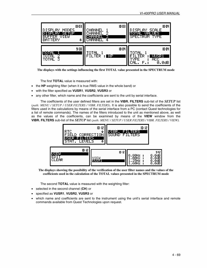
VI-400PRO USER MANUAL
4 - 69
The displays with the settings influencing the first TOTAL value presented in the SPECTRUM mode
The first TOTAL value is measured with:
• the HP weighting filter (when it is true RMS value in the whole band) or
• with the filter specified as VUSR1, VUSR2, VUSR3 or
• any other filter, which name and the coefficients are sent to the unit by serial interface.
The coefficients of the user defined filters are set in the VIBR. FILTERS sub-list of the SETUP list (path: MENU / SETUP / USER FILTERS / VIBR. FILTERS). It is also possible to send the coefficients of the filters used in the calculations by means of the serial interface from a PC (contact Quest technologies for a list of remote commands). The names of the filters introduced to the unit as mentioned above, as well as the values of the coefficients, can be examined by means of the VIEW window from the VIBR. FILTERS sub-list of the SETUP list (path: MENU / SETUP / USER FILTERS / VIBR. FILTERS / VIEW).
The displays showing the possibility of the verification of the user filter names and the values of the coefficients used in the calculation of the TOTAL values presented in the SPECTRUM mode
The second TOTAL value is measured with the weighting filter:
• selected in the second channel (CH) or
• specified as VUSR1, VUSR2, VUSR3 or
• which name and coefficients are sent to the instrument using the unit’s serial interface and remote commands available from Quest Technologies upon request.

VI-400PRO USER MANUAL
4 - 70
The view of the displays with the settings influencing the TOTAL values presented in the SPECTRUM mode in selected CHANNEL
The third TOTAL value is measured with the weighting filter:
• selected in the third channel (CH) or • specified as VUSR1, VUSR2, VUSR3 or
• which name and coefficients are sent to the instrument using the unit’s serial interface and remote commands available from Quest Technologies upon request.
The view of the displays with the settings influencing the TOTAL values presented in the SPECTRUM mode The results of 1/3 OCTAVE analysis, so-called spectrum, can be presented as the acceleration,
velocity or displacement spectrum. The type of the spectrum is selected in the SPECTRUM TYPE window of the DISPLAY SETUP sub-list (path: MENU / DISPLAY / DISPLAY SETUP / CHANNEL x / SPECTRUM TYPE / ACCELERATION, VELOCITY or DISPLACEMENT).
The view of the displays with the settings influencing 1/3 OCTAVE analysis results presentation in the SPECTRUM mode
The results of 1/3 OCTAVE analysis are always calculated and saved as the acceleration
spectrum. The ACC text given in the first left column indicates that the acceleration spectrum is presented on the display.
In order to present the velocity spectrum the linear accelerometer value from each 1/3 OCTAVE filter is divided by 2ππππfc, where fc is the exact central frequency of the mentioned filter. The VEL text is presented in the first column of the display in this case indicating the type of the spectrum.
In order to present the displacement spectrum the linear velocity value from each 1/3 OCTAVE filter is divided by 2ππππfc, where fc is the exact central frequency of the mentioned filter. The DIL text is given in the first column of the display in this case indicating the type of the spectrum.

VI-400PRO USER MANUAL
4 - 71
The view of the displays in 1/3 OCTAVE analysis with the acceleration, velocity and displacement spectrum expressed in LINear (path: MENU / DISPLAY / DISPLAY SETUP / CHANNEL x / DISPLAY SCALE / LIN), METRIC
units (path: MENU / SETUP / VIBRATION UNITS / METRIC) for CHANNEL 1
The read-out of the desried spectrum value can be done by means of the cursor controlled by <3333>, <4444>. On the right side of the display the selected 1/3 octave filter center frequency (or the selected TOTAL) is given, the current time of registered spectrum, the numerical value corresponding to the position of the cursor and the units are displayed in the consecutive lines.
Note: The displayed units during the measurement or analysis of vibration signal depends on the different settings made in the VIBRATION UNITS (METRIC or NON-METRIC), the VIBR.SCALE position of DISPLAY SCALE (LIN or LOG) and the weighting FILTER set in CHANNELS x (for acceleration, velocity or displacement measurements).
The view of the displays with the different linear vibration units
The displays in 1/3 OCTAVE analysis with the acceleration, velocity and displacement spectrum expressed in LINear (path: MENU / DISPLAY / DISPLAY SETUP / CHANNEL x / DISPLAY SCALE / LIN), METRIC units (path:
MENU / SETUP/ VIBRATION UNITS / METRIC)
The view of the displays in 1/3 OCTAVE analysis with the acceleration, velocity and displacement spectrum expressed in LINear (path: MENU / DISPLAY / DISPLAY SETUP / CHANNEL x / DISPLAY SCALE / LIN), NON-
METRIC units (path: MENU / SETUP / VIBRATION UNITS / NON METRIC)
The view of the displays with the different display scale; LINear or LOGrithmic units selection

VI-400PRO USER MANUAL
4 - 72
The view of the displays in 1/3 OCTAVE analysis with the acceleration, velocity and displacement spectrum expressed in LOGarithmic units (path: MENU / DISPLAY / DISPLAY SETUP / DISPLAY SCALE / LOG)
The view of the displays in 1/3 OCTAVE analysis with the acceleration spectrum expressed in LINear (path: MENU / DISPLAY / DISPLAY SETUP / CHANNEL x / DISPLAY SCALE / LIN), NON-METRIC units (path: MENU /
SETUP / VIBRATION UNITS / NON METRIC)
The view of the displays in 1/3 OCTAVE analysis with the acceleration spectrum expressed in LOGarithmic units (path: MENU / DISPLAY / DISPLAY SETUP / CHANNEL x / DISPLAY SCALE / LOG)
The view of the displays (path: MENU / DISPLAY / DISPLAY SETUP / CHANNEL x / TOTAL VALUES / TOTAL x / FILTER) with the different weighting filters (path: MENU / INPUT / CHANNELS SETUP / CHANNEL x) which can
influence the units of vibration results
The view of the displays in 1/3 OCTAVE analysis with the acceleration spectrum expressed in LINear (path: MENU / DISPLAY / DISPLAY SETUP / CHANNEL x / DISPLAY SCALE / LIN), METRIC (path: MENU / SETUP /
VIBRATION UNITS / METRIC) units; first TOTAL value selected as HP, second TOTAL value selected as CH and third TOTAL value selected as VUSR1 and in the first channel an acceleration (HP), displacement (Dil1)
or defined by user (VUSR1) filter selected

VI-400PRO USER MANUAL
4 - 73
The view of the displays in 1/3 OCTAVE analysis with the acceleration spectrum expressed in LINear, METRIC units; the first TOTAL value selected as HP acceleration filter; the second TOTAL value selected
as CH 2 and one of the displacement filters (Dil1) selected there or TOTAL 2 selected as USER VIBRATION filter; the third TOTAL value selected as CH 3 and one of the displacement filters selected there (Dil1) or
TOTAL 3 selected as USER VIBRATION displacement filter
The view of the displays with the same vibration 1/3 OCTAVE spectrum presented as acceleration, velocity or displacement in LOGarithmic units with the different DYNAMIC value (the <Altf> and <5555> or < Altf >
and <6666> push-buttons were also used for shifting up or down the vertical axis)
When the logarithmic units are selected for the presentation of 1/3 OCTAVE analysis results the displayed measurement values depend on the reference level set for the acceleration, velocity and displacement in the REFERENCE LEVEL window of the SETUP list (path: MENU / SETUP / REFERENCE LEVEL / VIBRATION).
The view of the displays with the different reference levels influencing the measurement vibration results presented in the logarithmic units (decibels)

VI-400PRO USER MANUAL
4 - 74
In One profile and 3 PROFILES display modes the results are presented in the same way as in the case of the VLM mode with only one difference that instead of the solid lines doted lines are used. The active channel is changed after each pressing of <Altf> and <5555> or <Altf> and <6666>. The change of the result from the same channel is done by pressing <3333>, <4444>.
The view of the displays in 1/3 OCTAVE analysis in One profile and 3 PROFILES display modes
In the PLOT mode the results are presented which are saved in the buffer from the channels (when text ON in the BUFFERS positions is selected and user selects in the CHANNEL x sub-lists position to display in PLOT mode. The selection of the OFF text means that the results are not saved in the buffer’s file.) with the step set for all channels in the BUF. STEP position. The active channel is changed after pressing <5555> and <6666>. The position of the cursor can be done after pressing <3333>, <4444>. It is also possible to shift the horizontal axis in relation to the vertical axis of the presented results using the <Altf> and <5555> or < Altf > and <6666> push-buttons (similarly as it has to be done in the SPECTRUM mode).
The view of the displays in 1/3 OCTAVE analysis in the PLOT mode; the registered results from
CHANNEL 1
In the SPECTRUM mode it is possible to shift the horizontal axis in relation to the vertical axis of the presented results using <Altf> and <5555> or <Altf> and <6666>. After each pressing of these buttons the presented picture moves 10 dB down or up respectively.
The view of the displays in 1/3 OCTAVE analysis with the shifted horizontal axis in relation to vertical axis; LOGarithmic units (path: MENU / DISPLAY / DISPLAY SETUP / CHANNEL x / DISPLAY SCALE / LOG); the next one
display is obtained from the previous one after TWO consecutive pressing of <Altf > and <6666>
The view of the displays in 1/3 OCTAVE analysis with the shifted horizontal axis in relation to vertical one; LINear (path: MENU / DISPLAY / DISPLAY SETUP / CHANNEL x / DISPLAY SCALE / LIN), METRIC (path: MENU / SETUP / VIBRATION UNITS / METRIC) vibration units; the next one display is obtained from the previous one
after ONE pressing of <Altf > and <6666>

VI-400PRO USER MANUAL
4 - 75
The spectra registered in the buffer’s file can be presented on the display in the BUFFER VIEW sub-list of the DISPLAY list. These spectra are saved with the same step as selected in the VLM profiles (see the description of the BUF. STEP position of the MEASURE SETUP sub-list).
In order to display the spectra registered in the buffer’s file the user has to:
- press <Altf> and <4444> push-buttons for the spectra stored later;
- press <Altf> and <3333> push-buttons for the spectra saved earlier.
In the BUFFER VIEW sub-list it is also possible to examine the time history for 1/3 OCTAVE filter selected by the cursor (see the description of the BUFFER VIEW sub-list in Chapter 5).
Notice: Many time histories can be saved in the buffer’s file of the instrument during the measurements performed in different sessions. The presentation of these results is possible using the BUFFER VIEW window of the DISPLAY list (path: MENU / DISPLAY / BUFFER VIEW) (see Chapter 5).
Measurement range selection in 1/3 OCTAVE analysis of vibration signal - RANGE The selection of the input range is possible after entering the RANGE position (path: MENU /
INPUT / CHANNEL x / RANGE) (from the INPUT/ CHANNEL x sub-list using <5555>, <6666> (or <3333>, <4444>) and pressing <ENTER>. The input ranges specified in Appendix C. The return to the CHANNEL x sub-list ignoring the changes is made after pressing <ESC> or confirming the selection after pressing <ENTER>.
The view of the displays with the RANGE (path: MENU / INPUT / CHANNEL x /RANGE) position selected
It is possible to change RANGE in VIBRATION mode. The instrument operates in two input ranges 117.8 m/s2 and 316 m/s2, which can be selected by means of the range position. In order to change the mode of the range the user has to press <3333>, <4444>.
The return to the CHANNEL x sub-list ignoring the changes is made after pressing <ESC> or confirming the selection after pressing <ENTER>.
The view of the displays with the RANGE (path: MENU / INPUT / CHANNEL x / RANGE) position selected in case of VIBRATION signal
Notice: It is not possible to change the range of the measurements during the execution of the measurements. It is possible to open different lists and sub-lists but the positions in these lists are not high lighted and therefore not accessible. The “Loudspeaker” icon indicates that the instrument is in the measurement process. In order to change the range the measurement must be finished!

VI-400PRO USER MANUAL
4 - 76
The view of the displays with RANGE position (path: MENU / INPUT / CHANNEL x / RANGE) not accessible.
Notice: If an OVERLOAD occurs it is signalled by the ”Bell” icon (cf. Chapter 3 for details).
Selection of 1/3 OCTAVE analysis result of vibration signal to be saved in the buffer’s file - BUFFERS SETUP
The measurements results from each channel can be saved in the buffer’s file of the instrument’s VLM mode. The selection of the OFF option means that no result from the described channel have to be saved in the buffer’s file. The user can switch OFF or ON BUFFERS position by pressing <3333> or <4444>. The selection of the OFF text means that the results are not saved in the buffer’s file. After pressing <ENTER> any changes made in the sub-list are confirmed and the sub-list is closed. Pressing <ESC> returns to the BUFFERS SETUP sub-list ignoring any changes made in the sub-list.
The view of the displays in the BUFFERS SETUP sub-list list (path: MENU / INPUT / BUFFERS SETUP); the selection of the BUFFERS store
The user can select the following results, which can be saved: PEAK, P–P, MAX and RMS for vibration measurement. The selection of the parameter from the CHANNEL x sub-list is made by pressing <5555>, <6666>. After pressing <ENTER> any changes made in the sub-list are confirmed and the sub-list is closed. Pressing <ESC> returns to the BUFFERS SETUP sub-list ignoring any changes made in the sub-list.
In order to switch parameters in the buffer, the user has to place special character in the chosen position; available values are: [√√√√] or [ ]. The selection of the required buffers parameter is made with <3333>, <4444>. The user can pass to the selection of the next parameter from the CHANNEL x sub-list pressing <5555>, <6666>. After pressing <ENTER> any changes made in the sub-list are confirmed and the sub-list is closed. Pressing <ESC> returns to the BUFFERS SETUP sub-list ignoring any changes made in the sub-list.
The view of the displays in the CHANNEL 1 sub-list; the selection of the parameters to be saved in the buffer’s file

VI-400PRO USER MANUAL
4 - 77
The view of the displays in the BUFFERS SETUP sub-list; the all the parameters were selected to be saved in the buffer’s file; in CHANNEL 1 and 2 vibration and in CHANNEL 3 and 4 sound parameters
Notice: The change of the channels parameters is not possible when the measurement is performed. The user has to finish the current measurement.
Notice: Setting BUFFER:OFF results in bypassing the storing of the given channel’s results in the buffer’s file. It creates more space in the buffer for other channels (see Chapter 5 for details).
Notice: The buffer is updated in the time periods (steps) defined in the BUF. STEP (path: MENU / INPUT / MEASURE SETUP / BUF. STEP). The way the measurement results are stored is described in Chapter 5.
Selection of 1/3 OCTAVE analysis parameters for vibration signal - SPECTRUM
The SPECTRUM sub-list (path: MENU/ INPUT/ 1/3 OCTAVE SETUP/ CHANNEL x/ SPECTRUM) is a context element, which appears on the INPUT sub-list in 1/1 OCTAVE or 1/3 OCTAVE mode.
The view of the displays in the 1/3 OCTAVE SETUP window with the SPECTRUM text
selected in CHANNEL x position
User can switch OFF or ON SPECTRUM position in selected channels by pressing <3333> or <4444>. After pressing <ENTER> any changes made in the sub-list are confirmed and the sub-list is closed. Pressing <ESC> returns to the INPUT sub-list ignoring any changes made in the sub-list.
Notice: CHANNEL 2, CHANNEL 3 and CHANNEL 4 position are not available. The user can not ON this CHANNEL to display SPECTRUM.

VI-400PRO USER MANUAL
4 - 78
Selection of 1/3 OCTAVE analysis result of vibration signal to be saved in the buffer’s file - BUFFER
The RMS result from 1/3 OCTAVE analysis can be saved in the buffer’s file of the instrument. The selection of the required result is made with <3333>, <4444>. The selection of the None text means that the RMS results are not saved in the buffer’s file. After pressing <ENTER> any changes made in the sub-list are confirmed and the sub-list is closed. Pressing <ESC> returns to the 1/3 OCTAVE SETUP/ CHANNEL x sub-list ignoring any changes made in the sub-list.
The view of the displays in the SPECTRUM sub-list (path: MENU / INPUT / PROFILES SETUP / 1/3 OCTAVE SETUP / CHANNEL x / SPECTRUM), the selection of the BUFFER position
Notice: It is not possible to change the values of the parameters during the execution of the measurements. It is possible to open different lists and sub-lists but the positions in these lists are not high lighted and therefore not accessible. The “Loudspeaker” icon indicates that the instrument is in the measurement process. In order to change the range the measurement must be finished!
The view of the displays with not accessible parameters of the 1/3 OCTAVE SETUP lists (path: MENU / INPUT / 1/3 OCTAVE SETUP),
Notice: All other settings of the instrument are common for 1/3 OCTAVE analyzer and the VLM.
Selection of the result which triggers registration in BUFFER mode in 1/3 OCTAVE analysis of vibration signal
In level meter mode only the result coming from the RMS detector of channel one is used for triggering purposes. In the case of vibration measurements it is VECT or RMS value. The SOURCE position is not accessible in that mode. However, in 1/3 OCTAVE analysis it is possible to access the above mentioned position and to make a selection. The results coming from the output of 1/3 OCTAVE filters, starting from 125 Hz (125 Hz, 160 Hz, 200 Hz, 250 Hz, …, 8.00 kHz, 10.0 kHz, 12.5 kHz, 16.0 kHz and 20.0 kHz), are available as well as RMS result from the one selected channel.

VI-400PRO USER MANUAL
4 - 79
…
The view of the displays in TRIGGER SETUP window; the selection of the signal used for triggering purposes in BUFFER mode; METRIC units selected
Notice: It is not possible to change the values of the parameters during the execution of the measurements. It is possible to open different lists and sub-lists but the positions in these lists are not high lighted and therefore not accessible. The “Loudspeaker” icon indicates that the instrument is in the measurement process. In order to change the range the measurement must be finished!
The view of the displays with not accessible parameters of the BUFFERS SETUP sub-lists
Notice: All other settings of the instrument are common for 1/3 OCTAVE analyzer and the level meter mode.

VI-400PRO USER MANUAL
4 - 80

VI-400PRO USER MANUA
5 - 1
5. AUXILIARY FUNCTIONS 5.1. DATA AVAILABLE ON THE DISPLAY - DISPLAY LIST
In order to open the DISPLAY list the user has to: • press <Altf> and <MENU>, • select from the main list, using <5555>, <6666> (or <3333>, <4444>), high light the DISPLAY text, • press <ENTER>.
Pressing the <Altf> and <5555> (or <Altf> and <3333>) results in a movement to the first position of the opened list and pressing the <Altf> and <6666> (or <Altf> and <4444>) results in a movement to the last position of the opened list.
The view of the display in the main list; the DISPLAY text high lighted
The DISPLAY list is used for setting the various parameters which are mainly dedicated for the
control of the display. The following items are present on this list:
DISPLAY MODES enables one to select the display mode (the way measurement results are presented);
DISPLAY SETUP enables one to change the scale in the graphical display modes, select the results presented as Total values, choose the type of the presented spectrum for each channel separately;
BUFFER VIEW enables one to view at the results stored in the files of the buffer; BATTERY enables one to check the state of the internal battery of the unit; CONTRAST enables one to set the contrast of the unit’s display; BACKLIGHT enables one to set the brightness of the backlight of the display and the keyboard; UNIT LABEL informs the user about the serial number of the unit, the version of the internal
firmware and the standards to which the measurement results conform.
In each available position any change is performed by means of <3333>, <4444>. In order to confirm the selection the <ENTER> push-button has to be pressed. After this confirmation the opened window or list is closed. In order to ignore any changes made in the opened window or list the user has to press the <ESC> push-button.
The view of the displays with the DISPLAY list Selection of the modes of measurement results presentation - DISPLAY MODES The DISPLAY MODES (path: MENU / DISPLAY / DISPLAY MODES) sub-list enables the selection of
the currently available modes of displaying the results of measurement. The selection is made by placing

VI-400PRO USER MANUAL
5 - 2
or replacing the special character in the high lighted displayed position of the DISPLAY MODES sub-list by means of <3333>, <4444>. In order to confirm the selection the user has to press <ENTER>. The mode of the display is related with the selection of the instrument’s function (SLM or VLM, 1/1 OCTAVE, 1/3 OCTAVE or FFT analyzer). Only One Profile display mode cannot be switched off independently from the current display mode of the instrument.
For the Sound Level Meter or Vibration Level Meter the following possibilities of display modes are available: - One Profile, - 3 PROFILES, - STATISTICS, - PLOT (time history).
The SPECTRUM position is never available for the Sound Level Meter or Vibration Level Meter (it is never high lighted).
a) b)
The view of DISPLAY MODES (path: MENU / DISPLAY / DISPLAY MODES) sub-list for the SLM or VLM with all possibilities switched on (a) and STATISTICS and PLOT switched off (b)
For the frequency analysis of the measured signal (1/1 OCTAVE, 1/3 OCTAVE the following display modes are available: - One Profile, - SPECTRUM, - 3 PROFILES, - STATISTICS, - PLOT (time history).
a) b)
The view of the DISPLAY MODES sub-list with all possibilities of results presentation for the frequency analysis switched on (a) and STATISTICS and PLOT switched off (b)
The PLOT display mode is available if data from at least one channel are logged in the buffer’s file. If the BUFFERS position, in BUFFERS SETUP sub-list, is switched ON but there was nothing stored in the buffer’s file (in the selected channel there was nothing switched on ([√√√√])) instead of PEAK, MAX, MIN or RMS), the NO RESULTS text is displayed after the first input to this mode (see Figure below). When the BUFFERS are selected as non-active BUFFER:OFF and for all channels are set, the PLOT mode of results presentation is skipped.
There is PLOT display, when the BUFFERS position is switched ON and user selected position to display in BUFFERS SETUP/ CHANNEL x ([√√√√])

VI-400PRO USER MANUA
5 - 3
The view of the display in the PLOT mode when there is nothing in the buffer to be displayed (after setting PLOT as active)
Each position of the DISPLAY MODES sub-list can be switched on or off independently. The sub-list is closed and the instrument returns to the DISPLAY list, ignoring changes made in the DISPLAY MODES sub-list after pressing <ESC> or confirming changes made in the DISPLAY MODES sub-list after pressing <ENTER>.
Selection of the parameters in graphical results presentations - DISPLAY SETUP The DISPLAY SETUP (path: MENU / DISPLAY / DISPLAY SETUP) sub-list enables the user to
change several parameters of the graphical results presentations for each channel separately. Namely one can select, using the DISPLAY SCALE sub-list, the scale in the available modes of graphical presentation of the measurement results (time history in the PLOT and so-called spectra in the SPECTRUM). Using the TOTAL VALUES sub-list it is possible to select the weighted filters used in the calculation of the Total values. This sub-list appears on the display only in the case of 1/1 OCTAVE or 1/3 OCTAVE analyzer. Using the SPECTRUM TYPE sub-list it is possible to select the type of the spectrum which has to be presented during vibration measurements. This sub-list appears on the display only in the case of the VIBR. METER mode selection. In order to enter the DISPLAY SETUP list one has to press <ENTER> on the high lighted DISPLAY SETUP text of the DISPLAY list. The DISPLAY SETUP sub-list is closed and the instrument returns to the DISPLAY list after pressing <ESC>, which ignores any changes in the positions of the sub-list or <ENTER>, which confirms the changes.
The view of the display with the DISPLAY list, the DISPLAY SETUP text highlighted The DISPLAY SCALE (path: MENU / DISPLAY / DISPLAY SETUP / CHANNEL x / DISPLAY SCALE)
sub-list enables the user to change the scale in the available modes of graphical presentation of the measurement results (time history in the PLOT and so-called spectra in the SPECTRUM). It can be done in the SCALE position of the DISPLAY SCALE sub-list. The user can set the parameters for each channel separately. It is also possible to change the “dynamics” of the vertical axis by means of the DYNAMIC position. In order to enter this list one has to press <ENTER> on the high lighted DISPLAY SCALE text of the DISPLAY SETUP/ CHANNEL x list. The DISPLAY SCALE sub-list is closed and the instrument returns to the CHANNEL x list after pressing <ESC>, which ignores any changes in the positions of the sub-list or <ENTER>, which confirms the changes.
The view of the display with the DISPLAY SETUP list, the DISPLAY SCALE text highlighted

VI-400PRO USER MANUAL
5 - 4
Selection of the scale in graphical results presentations - DISPLAY SCALE The DISPLAY SCALE (path: MENU / DISPLAY / DISPLAY SETUP / CHANNEL x / DISPLAY SCALE)
sub-list enables the user to change the scale in the available modes of graphical presentation of the measurement results (time history in the PLOT and so-called spectra in the SPECTRUM). It is possible to change the scale of the vertical axis only. In order to enter this list one has to press <ENTER> on the high lighted DISPLAY SCALE text of the DISPLAY SETUP sub-list. The DISPLAY SCALE sub-list is closed and the instrument returns to the DISPLAY SETUP sub-list after pressing <ESC>, which ignores any changes in the positions of the sub-list or <ENTER>, which confirms the changes.
The view of the display with the DISPLAY list, the DISPLAY SCALE text highlighted This position can be active only in the case of vibration measurements (when in the MODE sub-list
the VIBR. METER is selected). Two options are available: LIN (linear) and LOG (logarithmic). In the case of linear the graphical presentation and the units both are linear. In the case of logarithmic the graphical presentation is given in the logarithmic scale and the measurement results are expressed in decibels (the result is related to the values set in the REFERENCE LEVEL). It is possible to set the required option using <3333>, <4444>. The confirmation of the selection is made by pressing <ENTER>. The return ignoring any change is made after pressing <ESC>.
The view of the displays with the possible options of the VIBRATION SCALE Scaling of the vertical axis of the graphical presentation - DYNAMIC For the vertical axis the user can obtain the double, four times and eight times expansion (as the
default the vertical axis corresponds to 80 dB, after expansion it corresponds to 40 dB, 20 dB and 10 dB – respectively) using <3333>, <4444>. This setting is always valid only for the measurements of sound and for vibrations if the LOGarithmic scale was selected.
The view of the displays with the possible values of the vertical axis in PLOT and SPECTRUM presentations
Scaling of the horizontal axis of the graphical presentation - X-ZOOM It is not possible in version 2.17 of the internal firmware, to change by means of <3333>, <4444> the
horizontal axis (the default value of the multiplier of this axis is equal to 1).

VI-400PRO USER MANUA
5 - 5
Selection of the weighted Filters - TOTAL VALUES The TOTAL VALUES (path: MENU / DISPLAY / DISPLAY SETUP/ CHANNEL x / TOTAL VALUES)
sub-list which is available only in 1/1 OCTAVE or 1/3 OCTAVE analysis; enables the user to select the weighted filters. In order to enter this list one has to press <ENTER> on the high lighted TOTAL VALUES text of the DISPLAY SETUP/ CHANNEL x list. The TOTAL VALUES sub-list is closed and the instrument returns to the CHANNEL x list after pressing the <ESC> push-button.
The view of the display with the DISPLAY SETUP list, the TOTAL VALUES text highlighted (path: MENU / DISPLAY / DISPLAY SETUP / CHANNEL x / TOTAL VALUES)
Selection of the Weighted Filters for the 1st profile - TOTAL 1
The TOTAL 1 sub-list enables one to select the weighted filter to be used for the calculation of the TOTAL value in the first profile (FILTER). In the case of vibration measurements it is also possible to determine the type (TYPE) of the filter and the calibration coefficient (CAL. F.). The TOTAL 1 sub-list is closed and the instrument returns to the TOTAL VALUES list after pressing <ESC>, which ignores any changes in the positions of the sub-list or <ENTER>, which confirms the changes.
FILTER: (position); available values of the weighted filters: o for sound measurements: A, SUSR1, SUSR2, SUSR3 or any other sent to the unit by means
of the serial interface,
The view of the displays with the TOTAL 1 list opened in the case of sound measurements
o for vibration measurements: HP, VUSR1, VUSR2, VUSR3 or any other sent to the unit by means of the serial interface.
The view of the displays with the TOTAL 1 list opened in the case of vibration measurements
TYPE: (position available only for vibration measurements); available values if VUSR1, VUSR2, or VUSR3 was selected in the previous position: ACC, VEL and DIL; if the HP filter was selected in the previous position this position is not displayed.
The displays with the TOTAL 1 list opened in the case of vibration measurements; USER3 filter selected

VI-400PRO USER MANUAL
5 - 6
CAL. F.: (position available only for vibration measurements); accessible if VUSR1, VUSR2, or VUSR3 was selected in the FILTER position; if the HP filter was selected this position is not displayed; available values (from -60.0dB to 60.0dB with 0.1dB step by pressing <3333>, <4444> or with 1 dB step by pressing <Altf> with <3333>, <4444>).
The displays with the TOTAL 1 list opened in the case of vibration measurements; calibration factor setting
Selection of the Weighted Filters for the 2nd profile - TOTAL 2
The TOTAL 2 sub-list enables one to select the weighted filter to be used for the calculation of the TOTAL value in the second profile (FILTER), its type (TYPE) and the calibration coefficient (CAL. F.). The TOTAL 2 sub-list is closed and the instrument returns to the TOTAL VALUES list after pressing <ESC>, which ignores any changes in the positions of the sub-list or <ENTER>, which confirms the changes.
FILTER: (position); available values of the weighted filters: o for sound measurements: C, SUSR1, SUSR2, SUSR3 or any other sent to the unit by means
of the serial interface,
The view of the displays with the TOTAL 2 list opened in the case of sound measurements
o for vibration measurements: CH, VUSR1, VUSR2, VUSR3 or any other sent to the unit by means of the serial interface.
The view of the displays with the TOTAL 2 list opened in the case of vibration measurements
TYPE: (position available only for vibration measurements); available values if VUSR1, VUSR2 or VUSR3 was selected in the previous position: ACC, VEL and DIL; if the CH filter was selected (the filter which was set in the 2nd channel) this position is not displayed. CAL. F.: (position available only for vibration measurements); accessible if VUSR1, VUSR2 or VUSR3 was selected in the FILTER position; if the CH filter was selected (the filter which was set in the 2nd channel) this position is not displayed; available values (from -60.0dB to 60.0dB with 0.1dB step by pressing <3333>, <4444> or with 1 dB step by pressing <Altf> with <3333>, <4444>).
Selection of the Weighted Filters for the 3rd profile - TOTAL 3
The TOTAL 3 sub-list enables one to select the weighted filter to be used for the calculation of the TOTAL value in the third profile (FILTER), its type (TYPE) and the calibration coefficient (CAL. F.). The TOTAL 3 sub-list is closed and the instrument returns to the TOTAL VALUES list after pressing <ESC>, which ignores any changes in the positions of the sub-list or the <ENTER>, which confirms the changes.

VI-400PRO USER MANUA
5 - 7
FILTER: (position); available values of the weighted filters: o for sound measurements: LIN, SUSR1, SUSR2, SUSR3 or any other sent to the unit by
means of the serial interface,
The view of the displays with the TOTAL 3 list opened in the case of sound measurements
o for vibration measurements: CH, VUSR1, VUSR2, VUSR3 or any other sent to the unit by means of the serial interface.
The view of the displays with the TOTAL 3 list opened in the case of vibration measurements
TYPE: (position available only for vibration measurements); available values if VUSR1, VUSR2 or VUSR3 was selected in the previous position: ACC, VEL and DIL; if the CH filter was selected (the filter which was set in the 3rd channel) this position is not displayed. CAL. F.: (position available only for vibration measurements); accessible if VUSR1, VUSR2 or VUSR3 was selected in the FILTER position; if the CH filter was selected (the filter which was set in the 3rd channel) this position is not displayed; available values (from -60.0dB to 60.0dB with 0.1dB step by pressing <3333>, <4444> or with 1 dB step by pressing <Altf> with <3333>, <4444>.
Selection of the Spectrum Type - SPECTRUM TYPE
The SPECTRUM TYPE (path: MENU / DISPLAY / DISPLAY SETUP / CHANNEL x / SPECTRUM TYPE) (position) enables the user to change the spectrum type; available values of this position: ACCELERATION, VELOCITY and DISPLACEMENT. This sub-list is available only for the vibration measurements. For sound measurements there are two other values of this position: RMS – for filter LIN and C, LEQ – for filter A. The user can select filter in FILTER position (path: MENU / INPUT / CHANNELS SETUP / CHANNEL x / FILTER). In order to enter this list one has to press <ENTER> on the high lighted SPECTRUM TYPE text of the DISPLAY SETUP/ CHANNEL x list. The SPECTRUM TYPE sub-list is closed and the instrument returns to the CHANNEL x list after pressing <ESC>, which ignores any changes in the positions of the sub-list or <ENTER>, which confirms the changes.
The view of the display with the DISPLAY list, the SPECTRUM TYPE text highlighted (path: MENU / DISPLAY / CHANNEL x / SPECTRUM TYPE)
The view of the display with the SPECTRUM TYPE with the available values for VIBRATION measurements

VI-400PRO USER MANUAL
5 - 8
The view of the display with the SPECTRUM TYPE with the available values for SOUND measurements
Selection of the buffer’s file to the display presentation - BUFFER VIEW The BUFFER VIEW sub-list enables the user to examine the contents of the buffer. In order to
open this sub-list the user has to press <ENTER> when the BUFFER VIEW text is high lighted. The following parameters of the buffer are presented on the instrument’s display: • The selected number of the file in the buffer and the number of all saved files (NO:). • The number of the records in the file, which number is displayed in the previous line (RECS:). • The size of the empty, still available memory (FREE:).
The view of the display with the DISPLAY list, the BUFFER VIEW text highlighted (path: MENU / DISPLAY / BUFFER VIEW)
The type of the measurement results stored in the buffer in channel 1, 2, 3, 4 (chosen in the
CHANNEL x sub-list of the CHANNELS SETUP sub-list) as well as the results selected for the registration in the case of 1/1 OCTAVE or 1/3 OCTAVE analysis (chosen in the BUFFERS SETUP sub-list of the INPUT sub-list) are given on the right side of the display. The change of the number of the file in the buffer is done after pressing the <3333>, <4444> push-buttons.
The view of the displays with the BUFFER VIEW sub-list opened: the selection of the file to be seen
The display of the instrument after entering the BUFFER VIEW sub-list looks as shown in the figure below when the buffer is empty (there was no measurement or the measurements were performed but with the settings for all channels and the spectrum BUFFER: ON on the 1/1 OCTAVE SETUP, 1/3 OCTAVE SETUP sub-list).
a) b) The view of the display with BUFFER VIEW sub-list in the case when there are no files in the buffer in the
unit with 8 MB of internal memory (a) and with 32 MB of internal memory (b)

VI-400PRO USER MANUA
5 - 9
The contents of the selected file from the buffer is displayed after pressing <ENTER>. The cursor position is changed after pressing <3333>, <4444>. The type of the registered result, the number of the channel the result is coming from, the related time from the beginning of the registration, the value with the units and the indicator of the filter are presented on the right side of the display.
The view of the displays with the selected file from the buffer; the change of the cursor position
The scrolling of the display is made when the cursor is at the left or right limits of the graphical display and <3333>, <4444> are still pressed and there are still results in the file.
The view of the displays with the selected file from the buffer; the scrolling to the right
The view of the displays with the selected file from the buffer; the scrolling to the left
The position of the horizontal axis in relation to the vertical axis can be changed after pressing <5555>, <6666> together with the <Altf>.
The view of the displays with the selected file from the buffer; the change of the axis relation
The selected file in the buffer can contain the measurement results from up to 4 channels (i.e. PEAK1, MAX1, PEAK3, MIN3, PEAK4, MAX4, MIN4, RMS4, PEAK1, MAX1) and the spectra. The change of the displayed result is possible after pressing <5555> or <6666>. The results on the display are in this case changed in the cycle (i.e. CH1: PEAK -> CH1: MAX -> CH3: PEAK -> CH3: MIN -> CH4: PEAK -> CH4: MAX -> CH4: MIN -> CH4: RMS-> CH1: PEAK and so on).

VI-400PRO USER MANUAL
5 - 10
…
The view of the displays with the selected file from the buffer; the change of the result after pressing <5555> or <6666>
The spectra are registered in the file’s buffer with the same step as selected in the BUF. STEP position of the MEASURE SETUP sub-list. In order to display the registered spectra the user has to press <Altf> together with <4444> for the spectra stored later and to press <Altf> together with <3333> for the spectra saved earlier.
The view of the displays with the selected file from the buffer containing spectra; the change of the spectra after pressing <SHIFT> together with <3333> or <4444>
In the file of the buffer containing the results of 1/1 OCTAVE or 1/3 OCTAVE analysis also the time history for each filter is stored. The user can observe these values by pressing <ENTER>. The next pressing of <ENTER> or <ESC> causes the return to the displaying of spectrum.
The view of the displays with the selected file from the buffer containing spectra; the change between spectrum and time history after pressing <ENTER>
The user can observe the time history plot on the output of each octave or third octave filter as well as for the whole band (TOTAL value). For sound measurements the TOTAL values depend on the USER FILTERS setting in the SETUP list. If those filters are not active (switched to Off) three TOTAL values are displayed which were calculated with the A, C and LIN filters respectively. When those filters are active only one TOTAL (calculated with the A filter) is displayed together with the value calculated for SUSR1 and SUSR2 filters. When only one filter is active on the display TOTAL (A), TOTAL (C), SUSR2 or TOTAL (A), SUSR1, TOTAL (LIN) are presented, depending on which filter is active. Additionally, the view presented in the BUFFER VIEW depends on the selected MODE. The SUSR1 and SUSR2 values are available only when SOUND METER is chosen. When the user wants to observe the sound measurements saved in the buffer but the VIBR. METER is selected, all three TOTAL values calculated with the A, C and LIN filters are displayed in the BUFFER VIEW.

VI-400PRO USER MANUA
5 - 11
The view of the displays with the selected file from the buffer containing spectra; the TOTAL values and their time histories. Settings of the meter: DISPLAY SCALE: LOGarithmic (path: MENU /DISPLAY /DISPLAY SETUP / CHANNEL x / DISPLAY SCALE / LOG), TOTAL 1: HP (path: MENU / DISPLAY /
DISPLAY SETUP / CHANNEL x / TOTAL VALUES / TOTAL 1); TOTAL 2: CH: HP1 (path: MENU / DISPLAY / DISPLAY SETUP / CHANNEL x / TOTAL VALUES / TOTAL 2); TOTAL 3: CH: VUSR1 (path: MENU /DISPLAY /DISPLAY SETUP / CHANNEL x / TOTAL VALUES / TOTAL 3); SPECTRUM TYPE:ACCELERATION (path:
MENU / DISPLAY / DISPLAY SETUP / CHANNEL x /SPECTRUM TYPE)
For vibration measurement results the ACC and VEL filters are always switched on. The values presented in the BUFFER VIEW, when the VIBR. METER is selected, contain one TOTAL value calculated for the whole band with the HP filter and the values calculated with the ACC and VEL filters respectively. When the user wants to examine the contents of the buffer with the vibration measurements but the SOUND METER is active, the values for the ACC and VEL filters are not available. In this case only one TOTAL value is presented.
As it was mentioned above, the user can observe the time history for all 1/1 and 1/3 octave filters as well as TOTAL values after pressing <ENTER> on a required filter. In order to observe the time history for another filter (while being in time history window) the user has to press <5555> or <6666>. After pressing the <5555> push-button the time history for the higher frequency filter can be seen.
The view of the displays with the selected file from the buffer containing spectra; the change of the time histories of the filters (and the filters) after pressing <5555>
After pressing the <6666> push-button the time history for the lower frequency filter can be seen.
The view of the displays with the selected file from the buffer containing spectra; the change of the time histories of the filters (and the filters) after pressing <6666>
After pressing <ESC> (or <ENTER>) in time history the display presents the spectra corresponding
to the previously seen view.

VI-400PRO USER MANUAL
5 - 12
The view of the displays with the selected file from the buffer containing spectra; the change between time history and spectra after pressing <ENTER> for 500 Hz filter
Additionally, during the presentation of the results saved in the buffer, the dynamic of the drawing
can be changed. The required value has to be set in the DYNAMIC position of the DISPLAY SCALE sub-list of the DISPLAY list.
The view of the displays with the selected file from the buffer containing spectra; the time history of the MAX value from the third profile displayed with 80 dB, 40 dB and 20 dB dynamic (set in the
DISPLAY SCALE)
Also in this case (the different values of DYNAMIC) it is possible to change the relation of the axis by pressing <Altf> and <5555> or <Altf> and <6666>.
The view of the displays with the selected file from the buffer; the change of the axis relation The change of the axis relation for the time histories of the octave and third octave filters (after
pressing <Altf> and <5555> or <Altf> and <6666>) and the change of the dynamic of the presentation (the DISPLAY SCALE sub-list of the DISPLAY list) is also available. Below the time history for 250 Hz filter is presented with the 80 dB, 40 dB and 20 dB dynamic after changing the axis relation.
The view of the displays with the selected file from the buffer containing spectra; the time histories for 250 Hz filter displayed with 80 dB, 40 dB and 20 dB dynamic and with different relation of the axis
The window is closed and the instrument returns to the BUFFER VIEW sub-list after pressing
<ESC> the required number of times (this number depends on the displayed result).
Checking the state of the internal battery - BATTERY The BATTERY (path: MENU / DISPLAY / BATTERY) position enables the user to check the internal
battery condition. The current battery voltage is displayed together with its approximate state (in graphical form). The position is opened after pressing <ENTER> on the highlighted BATTERY text.

VI-400PRO USER MANUA
5 - 13
The view of the displays with the BATTERY position when the external power supply is not connected
If the instrument is switched on when the external power supply is connected the special message is displayed in the BATTERY position.
The view of the BATTERY (path: MENU / DISPLAY / BATTERY) position when the external power supply is connected to the instrument
The position is closed and the instrument returns to the DISPLAY list after pressing <ESC> or <ENTER>.
Setting the contrast of the display - CONTRAST
The CONTRAST (path: MENU / DISPLAY / CONTRAST) position enables the user to set the proper contrast of the display by using <3333>, <4444>. The position is opened after pressing <ENTER> on the highlighted CONTRAST text. The user can select 11 different values of this parameter.
The view of the display with the DISPLAY list, the CONTRAST text highlighted
Notice: The new value of the contrast is confirmed after each pressing of <3333> or <4444>, the new value is selected without any confirmation from the <ENTER> push-button.
The position is closed and the instrument returns to the DISPLAY list after pressing <ESC> or <ENTER>.

VI-400PRO USER MANUAL
5 - 14
The view of the displays with the CONTRAST position; the change of the display contrast
Setting the backlight parameters - BACKLIGHT
The BACKLIGHT (path: MENU / DISPLAY / BACKLIGHT) sub-list enables the user to set the parameters of the backlight of the display and the keyboard, using <3333>, <4444> or <5555>, <6666>. The user can set the backlight to automatically switch off after a certain period as well as set the brightness of the backlight. The sub-list is opened after pressing <ENTER> on the highlighted BACKLIGHT text.
The view of the display with the DISPLAY list, the BACKLIGHT text highlighted
Automatic switch off of the backlight - TIMEOUT
To conserve battery life the backlight should be used only when it is needed. It is possible to set the backlight so it will automatically switch off after a certain period. When this option is set, 30 seconds after pressing any push-button the backlight is switched off. If the backlight has automatically turned off, the next pressing of any push-button will cause the backlight to switch on. The confirmation of the selection is made by pressing <ENTER>. The return ignoring any change is made after pressing <ESC>.
a) b)
The view of the displays in the BACKLIGHT sub-list (a); the TIMEOUT position active (b)
Setting the brightness of the backlight - BRIGHTNESS
It is possible to change the brightness of the backlight using <3333>, <4444>. The user can select five different values of this parameter.
Notice: The new value of the brightness is confirmed after each pressing of <3333> or <4444> , the new value is selected without any confirmation from the <ENTER> push-button.

VI-400PRO USER MANUA
5 - 15
The view of the displays in the BACKLIGHT sub-list; the BRIGHTNESS position active The position is closed and the instrument returns to the DISPLAY list after pressing <ESC> or
<ENTER>.
Checking specification of the instrument - UNIT LABEL
The UNIT LABEL position (path: MENU / DISPLAY / UNIT LABEL) displays the type of the instrument, its serial number and the current firmware version installed. After pressing <3>, <4> or <5555>, <6666> the displayed text is scrolled on the display and the user can check the total size of internal memory and the number of standards fulfilled by the instrument. The position is closed and the instrument returns to the DISPLAY list after pressing <ESC> or <ENTER>.
a) b) c)
d) e) f)
g)
The view of the displays with the UNIT LABEL position selected (a) and entered (b) and after scrolling with <5555>, <6666> or <5555>, <6666> (c), (d), (e), (f) and (g)

VI-400PRO USER MANUAL
5 - 16
5.2. SETUP MENU
The SETUP (path: MENU / SETUP) list contains different sub-lists and positions. Some of them are directly related with sound measurements, some of them depend on the mode of the instrument (sound or vibration meter) and some are related with the settings of the instrument’s hardware components. In order to open the SETUP list the user has to: • press <Altf> with <MENU>, • select (highlight) the SETUP text from the main list, using <5555>, <6666> (or <3333>, <4444>), • press <ENTER>.
The view of the display in the main list; the SETUP text highlighted
In the SETUP list the following items are available:
LANGUAGE position which enables the user to set the Language as RUSSIAN or ENGLISH;
TIMER position which enables the user to set the Timer function;
RTC position which enables the user to set the Real Time Clock;
USER FILTERS sub-lists which enable the user to select, switch on or off and set the correcting values for all 1/1 and 1/3 octave filters for sound measurements; for vibration measurements the weighting filters are always switched on, the user can set the correcting coefficients;
STAT. LEVELS (sub-list) position available only in the sound meter mode. It enables the user to select ten statistics results to be saved in a file together with the main results. This position is not shown in the menu for vibration meter mode.
EXT. I/O SETUP sub-list which enables the user to set the input / output options for connection with external devices;
SHIFT MODE sub-list which enables the user to set the operating mode of the <Altf> and the <START / STOP> push-buttons;
CLEAR SETUP position which enables the user to return to the manufacture’s set up, except the coefficients set in the USER FILTERS;
RMS INTEGRATION position which enables the user to select the way of integration for the RMS measurement in the case of vibration meter or the LEQ measurement in the case of sound level meter;
REFERENCE LEVEL position which enables the user to select the reference level for the vibration measurements and which informs the user about the reference level in the sound measurements;
VIBRATION UNITS position which enables the user to select the vibration units in which the results of the measurements are to be given;
WARNINGS sub-list which enables the user to switch on or off the warnings which can be displayed during the operation of the instrument;
VECTOR DEF. sub-list which enables the user to select coefficients needed to calculate vibration vector, which is taken into account during the calculation of measurement results;
HAV/WBV DOSE sub-list which enables the user to select parameters presenting the EXPOSURE and VIBRATION DOSE measurements;
MENU LOCK position which enables the user to select the type of menu lock to be used, choices are NO LOCK, PARTIAL and FULL LOCK.

VI-400PRO USER MANUA
5 - 17
Pressing <Altf> and <5555> (or <Altf> and <3333>) results in a movement to the first position of the opened list and pressing <Altf> and <6666> (or <Altf> and <4444>) results in a movement to the last position of the opened list.
In each available position any change is performed by means of the <3333>, <4444> push-buttons. In order to confirm the selection the <ENTER> push-button has to be pressed. After this confirmation the opened window or list is closed. In order to ignore any changes made in the opened window or list the user has to press the <ESC> push-button.
The view of the displays with the SETUP list
Programming of the instrument’s internal timer - TIMER The TIMER (path: MENU / SETUP / TIMER) position enables the user to program the internal timer.
The instrument can turn itself on at the programmed time and perform measurements using the set up from when the unit was last turned off. In order to enter this position the user has to select the TIMER text in the SETUP list using <5555>, <6666> (or <3333>, <4444>) and press <ENTER>.
The view of the display in the SETUP list in the TIMER text highlighted
The operation of the TIMER (path: MENU / SETUP / TIMER) setting is performed in the same way as it was described in the case of the FILE NAME window. The selection of the setting parameter is performed using <5555>, <6666> and the change of its value using <3333>, <4444>. The user must then press <ENTER> to accept the changes made and return to the SETUP list or press <ESC> to ignore the changes made and return to the SETUP list.
The view of the TIMER position

VI-400PRO USER MANUAL
5 - 18
Programming of the instrument’s internal Real Time Clock - RTC The RTC (path: MENU / SETUP / RTC) position enables the user to program the internal Real Time
Clock. This clock is displayed in the top right corner of the instrument’s display. In order to enter this position the user has to select the RTC text in the SETUP list, using <5555>, <6666> (or <3333>, <4444>) and press <ENTER>.
a)
The view of the display in the SETUP list in the RTC text highlighted
The operation of the RTC setting is performed in the same way as it was described in the case of the FILE NAME window. The selection of the setting parameter is performed using <3333>, <4444> and the change of its value, using <5555>, <6666>. The parameter, which value has to be changed, is flashing.
The view of the RTC position
Notice: The new value of a parameter is confirmed after each pressing of <5555>, <6666> (new value is selected without any confirmation from the <ENTER> push-button).
The position is closed and the instrument returns to the SETUP list after pressing <ENTER> or <ESC>.
Setting the conditions for the diffuse field measurements - FIELD CORRECTION The MICROPHONE CORRECTION (path: MENU / INPUT / CHANNELS SETUP / CHANNEL x )
position is available only in the case of the sound measurements. It enables the user to set the proper conditions for making the measurements in the diffuse field. In order to enter this position the user has to select the FIELD CORRECTION text in the SETUP list, using <5555>, <6666> (or <3333>, <4444>), and press <ENTER>.

VI-400PRO USER MANUA
5 - 19
The view of the display in the CHANNELx SETUP list in sound measurements(path: MENU / INPUT / CHANNELS SETUP / CHANNEL x ), the MIC. CORRECTION text highlighted
In the MICROPHONE CORRECTION position two options are available: DIFFUSE FIELD for
sound measurement performed in the diffuse field conditions and OUTDOOR for sound measurement performed outdoors. The B&K4936 microphone, part number 59-523, supplied with the VI-400PRO instrument is designed for sound measurement performed in the free field condition. In order to make the measurements in the diffuse field conditions the user has to switch on an additional correcting filter. The frequency characteristic of this filter is given in App. D. For the measurements performed with the use of the microphones for the diffuse field conditions the option DIFFUSE should be used.
In order to select the filter the user has to place the special character next to the chosen position by pressing <3333>, <4444>, available values are: [√√√√] or [ ]. The position of the sub-list can be changed by pressing <5555>, <6666>. The sub-list is closed and the instrument returns to the CHANNEL x sub-list after pressing <ENTER> confirming changes made in the positions or <ESC> ignoring changes made in the positions.
The displays in the MIC. CORRECTION position of the CHANNEL x sub-list, the field conditions selection for sound measurements
Introduction of the filter coefficients for 1/3 (1/1) OCTAVE analysis - USER FILTERS
The USER FILTERS (path: MENU / SETUP / USER FILTERS) sub-list enables the user to introduce the values of the correcting coefficients taken into account in 1/1 OCTAVE or 1/3 OCTAVE analysis. The results of the analysis can be modified by the introduced factors and so calculated TOTAL values for one or two active (set to On) sets of the filters presented on the display. In order to enter this sub-list the user has to select the USER FILTERS text in the SETUP list, using <5555>, <6666> (or <3333>, <4444>) and press <ENTER>. The texts which appear after pressing <ENTER> depends on the position set in the MODE sub-list.
a)
The view of the display in the SETUP list the USER FILTERS text highlighted

VI-400PRO USER MANUAL
5 - 20
USER FILTERS (sub-list) contains 2 sub-lists:
VIBR. FILTERS
• VIEW (position) o VIEW enables the user to select which filter should be viewed; the available options are
VUSR1, VUSR2, VUSR3 and any other transmitted to the instrument from a PC by means of the USB interface After pressing <ENTER> another sub-list opens containing the values of filters used in 1/1 OCTAVE or 1/3 OCTAVE analysis and saved under the name VUSR1, VUSR2, VUSR3 or any other
• EDIT (position) o EDIT- enables the user to select which filters should be edited; the available options are as
follows: VUSR1, VUSR2, VUSR3 or any other transmitted t o the instrument from a PC by means of the USB interface After pressing <ENTER> another sub-list opens containing the values of the filters used in 1/1 OCTAVE or 1/3 OCTAVE analysis; the user can set the values of correcting coefficients for all 1/3 OCTAVE filters:
0.80 Hz: available values of 0.8 Hz center frequency filter: -100.0dB ... 100.0dB 1.00 Hz: available values of 1Hz center frequency filter: -100.0dB ... 100.0dB ... … 20.0kHz: available values of 20 kHz center frequency filter: -100.0dB ... 100.0dB
• CLEAR (position)
• CLEAR enables the user to select which filters should be cleared; the available options are as follows: ALL, VUSR1, VUSR2, VUSR3 or any other
SOUND FILTERS
• VIEW o VIEW enables the user to select which filter should be viewed; the available options are
SUSR1, SUSR2, SUSR3 and any other transmitted to the instrument from a PC by means of the USB interface After pressing <ENTER> another sub-list opens containing the values of filters used in 1/1 OCTAVE or 1/3 OCTAVE analysis and saved under the name SUSR1, SUSR2, SUSR3 or any other
• EDIT o EDIT- enables the user to select which filters should be edited; the available options are as
follows: SUSR1, SUSR2, SUSR3 or any other transmitted to the instrument from a PC by means of the USB interface After pressing <ENTER> another sub-list opens containing the values of the filters used in 1/1 OCTAVE or 1/3 OCTAVE analysis; the user can set the values of correcting coefficients for all 1/3 OCTAVE filters:
0.80 Hz: available values of 0.8 Hz center frequency filter: -100.0dB ... 100.0dB 1.00 Hz: available values of 1Hz center frequency filter: -100.0dB ... 100.0dB ... … 20.0kHz: available values of 20 kHz center frequency filter: -100.0dB ... 100.0dB
• CLEAR (position)
• CLEAR enables the user to select which filters should be cleared; the available options are as follows: ALL, SUSR1, SUSR2, SUSR3 or any other

VI-400PRO USER MANUA
5 - 21
The selection of the position in this sub-list is performed by means of <5555>, <6666> (or <3333>, <4444>). The sub-list is closed and the instrument returns to the SETUP list after pressing <ESC> push-button (ignoring a change made in the position). After pressing <ENTER> on the highlighted text the proper sub-list is opened.
The display’s view in the USER FILTERS sub-list in vibration measurements, the selection of the position
Setting the coefficients of the user filters set - EDIT (position)
After pressing <ENTER> when the VUSR1 (in the EDIT position) text is highlighted, the sub-list containing the status of the selected set and the values of the coefficients for all 1/3 OCTAVE filters is opened. The status position informs the user that the set is switched on. It is not possible to change the status.
The view of the display in the EDIT sub-list, setting the coefficients The selection of the position in the set is performed by means of <5555>, <6666>. The value is
introduced by pressing <3333>, <4444>. The sub-list is closed and the instrument returns to the USER FILTERS sub-list after pressing <ENTER> confirmating all settings made in the sub-list or <ESC> ignoring all settings made in the sub-list.
Clearing the coefficients of the user filters - CLEAR
The CLEAR position enables the user to clear the values of the user coefficients of octave or third octave filters. It is possible to clear all sets of coefficients (ALL), to clear the first set (VUSR1), to clear the second set (VUSR2) or to clear the third one (VUSER3) in vibration measurements as well ALL, SUSR1, SUSR2 and SUSR3 in sound measurements respectively.
The view of the displays in the USER FILTERS; the CLEAR position selected
The coefficients of a set (or sets) are cleared after the selection of the proper text by means of
<3333>, <4444> and after pressing <ENTER>.

VI-400PRO USER MANUAL
5 - 22
The view of the displays in the CLEAR position in sound measurements
The view of the displays in the CLEAR position in vibration measurements
Selection of statistics levels to be saved in a file - STAT. LEVELS The STAT. LEVELS (path: MENU / SETUP / STAT. LEVELS) sub-list enables the user to select ten
statistics from one hundred calculated in the instrument to be saved in a file together with the main results of the measurements. This sub-list is available only in sound mode; in vibration mode it does not appear in the SETUP list.
The view of the display in the SETUP list in sound measurements, the STAT. LEVELS text highlighted In order to enter this sub-list the user has to select (highlight) the STAT. LEVELS text in the
SETUP list, using <5555>, <6666> (or <3333>, <4444>) and press <ENTER> .
The view of the displays in the STAT. LEVELS sub-list The selection of the position in the sub-list (the proper Ni, where i = 1,…, 10) is performed by
means of <5555>, <6666>. The selection of a number from 1 to 99 in all ten Ni positions is done in steps equal to 1 by means of <3333>, <4444> or in steps equal to 10 by means of <Altf> with <3333>, <4444>. The sub-list is closed and the instrument returns to the SETUP list after pressing <ENTER> with the confirmation of all settings made in the sub-list or <ESC> ignoring all settings made in the sub-list.

VI-400PRO USER MANUA
5 - 23
Selection of the external mode - EXT. I/O SETUP
The EXT. I/O SETUP sub-list (path: MENU / SETUP / EXT. I/O SETUP) enables the user to select the output or input device. The additional output socket, called AC / Int, enables one to connect the VI-400Pro with another device. On this socket the signal from the input or output of the analog-to-digital converter (before the correction) is available. This signal can be registered using a magnetic recorder, observed on an oscilloscope or used as a trigger measurement. It is possible to connect three types of input/output devices: ANALOG, DIGITAL IN and DIGITAL OUT.
This position enables the user to set the proper external device. In order to enter this position the user has to select the EXT. I/O SETUP text in the SETUP list, using <5555>, <6666> (or <3333>, <4444>), and pressing <ENTER>.
The view of the display in the SETUP list in sound measurements, the EXT. I/O SETUP text highlighted
In the MODE position of EXT. I/O SETUP sub-list three options are available: ANALOG, DIGITAL IN and DIGITAL OUT. In order to select the external device user has to press the <3333>, <4444> push-buttons. The position is closed and the instrument returns to the SETUP list after pressing the <ENTER> (with the confirmation of a change made in the position) or <ESC> push-button (ignoring a change made in the position).
The displays in the EXT. I/O SETUP position, the selection different I/O devices
• ANALOG – in this mode the meter can give signals to the output device. For example the signal can be observed on the oscilloscope from the selected CHANNEL. The user may choose CHANNEL 1, 2, 3 or 4.
The channel position enables the user to set the external channel. In order to enter this position the user has to select the CHANNEL text in the EXT. I/O SETUP list, using <5555>, <6666>. After selection of the CHANNEL the user has to press <3333>, <4444>. The position is closed and the instrument returns to the SETUP list after pressing <ENTER> confirming changes made in the position or <ESC> ignoring changes made in the position.
The displays in the EXT. I/O SETUP position, the channel selection for output signal

VI-400PRO USER MANUAL
5 - 24
• DIGITAL IN – in this mode the meter is connected to the output device which triggers it to undertake measurements. It starts to measure, when it’s input has a triggering impulse. In this mode the instrument works in EXT.TRIGGER function.
• DIGITAL OUT – in this mode the meter is connected to output device which is triggered by the VI-400Pro to measure. The VI-400Pro sends a digital trigger pulse to another device. In this mode the instrument works in TRIGGER PULSE function.
This I/O connection is especially important when the user wants to simultaneously measure the noise or vibration in more than 4 channels by using two VI-400Pro units. These I/O connections synchronize both instruments.
Selection of few push-buttons mode - SHIFT MODE The SHIFT MODE (path: MENU / SETUP / SHIFT MODE) sub-list enables the user to program the
operation mode of the <Altf> and <START / STOP> push-buttons.
The view of the display in the SETUP list the SHIFT MODE text highlighted In order to enter this position the user has to select the SHIFT MODE text in the SETUP list, using
<5555>, <6666> (or <3333>, <4444>) and pressing <ENTER>. The selection of a parameter in both positions is done by means of <3333>, <4444> and confirmed by pressing <ENTER>.
Selection of the working mode of <Altf> push-button - SHIFT In the SHIFT (path: MENU / SETUP / SHIFT MODE) position the user can choose between Shift and
2nd Fun.. When the Shift text is selected the <Altf> push-button operates as in the keyboard of a computer – in order to achieve the desired result the second push-button has to be pushed simultaneously with the <Altf> push-button.
When the 2nd Fun. text is selected the <Altf> push-button operates in sequence with the other push-button (<Altf> must be pressed and released and then the second push-button must be pressed and released). This mode is additionally signalled by the flashing 2n dF text placed instead of the Clock icon. This flashing starts after pressing the <Altf> and lasts till pressing any other push-button.
In order to select a desired mode of the <Altf> push-button <3333>, <4444> should be pressed. In order to confirm the selection and close the sub-list press <ENTER>. Pressing <ESC> the sub-list is also closed but all changes which were made are ignored.
The view of the displays in the SHIFT MODE sub-list; the available settings in the SHIFT position

VI-400PRO USER MANUA
5 - 25
Selection of the working mode of <START / STOP> push-button - ST/SP
In the ST/SP (path: MENU / SETUP / SHIFT MODE) position the user can choose between Normal and Inverse. When the Normal text is selected the <START / STOP> push-button operates as it is described in Chapter 2 – the instrument reacts on each of its pressing, starting or stopping the measurements.
When the Inverse text is selected the <START / STOP> push-button operates in conjunction or in a sequence with the <Altf> push-button. The measurements are started or stopped after pressing both push-buttons.
In order to select a desired mode of the <START / STOP> push-button <3333>, <4444> should be pressed. In order to confirm the selection <ENTER> has to be pressed. Such pressing closes the sub-list. After pressing <ESC> the sub-list is also closed but all changes which were made are ignored.
The view of the displays in the SHIFT MODE sub-list; the available settings in the ST/SP position
Return to the factory made settings - CLEAR SETUP The CLEAR SETUP (path: MENU / SETUP / CLEAR SETUP) position enables the user to return to
the manufacturer’s default set up of the instrument. In order to enter this position the user has to select the CLEAR SETUP text in the SETUP list, using <5555>, <6666> (or <3333>, <4444>) and press <ENTER>. After entering this position the request for the confirmation is displayed. The position is closed without any action and the instrument returns to the SETUP list after pressing <ESC>.
The view of the display in the SETUP list, the CLEAR SETUP text highlighted (displayed inversely)
The proper answer for the request is selected using <3333>, <4444>. The instrument returns to the
default set up after pressing <ENTER> when the answer YES was chosen. During the process of the resetting the message “Wait…” is displayed:
The view of the display during the execution of the CLEAR SETUP operation

VI-400PRO USER MANUAL
5 - 26
The following message is displayed after the return to the default settings and the instrument waits for the user’s reaction.
a) b) c)
The displays with the request for the confirmation for the CLEAR SETUP position execution (a), (b) and after the execution of the function (c)
The window is closed and the instrument returns to the SETUP list after pressing any push-button with an exception of the <Altf> one.
Selection of detector’s type in the LEQ (RMS) calculations - RMS INTEGRATION The RMS INTEGRATION (path: MENU / SETUP / RMS INTEGRATION) position enables the user to
select the detector type for the calculations of the LEQ function for sound measurements or the RMS function for vibration measurements. In order to enter this position the user has to select the RMS INTEGRATION text in the SETUP list, using <5555>, <6666> (or <3333>, <4444>) and press <ENTER>.
The view of the display in the SETUP list with the RMS INTEGRATION text highlighted
Two options are available: LINEAR and EXPONENTIAL. The required parameter can be selected using <3333>, <4444>. The position is closed and the instrument returns to the SETUP list after pressing <ENTER> with the confirmation of a change made in the position or <ESC> ignoring a change made in the position.
The expressions used for the LEQ or RMS calculations are given in Appendix D. Setting LINEAR is required for the IEC 61672-1 standard (for getting the true RMS value of the measured signal). When this option is selected for sound measurements, the value of the LEQ and SEL function (the SLM case) does not depend on the detector time constant (the results are displayed without the indicator of the detectors selected in the profiles).
The view of the displays with the available options of the RMS INTEGRATION position
Setting EXPONENTIAL enables the user to fulfil the requirements of the IEC 804 standard for the LEQ measurements. When this option is selected for sound measurements, the value of the LEQ and SEL function (the SLM case) depend on the detector time constant (the results are displayed with the indicator of the detectors selected in the profiles).

VI-400PRO USER MANUA
5 - 27
For sound measurements, setting EXPONENTIAL enables the user to fulfil the requirements of the IEC 804 standard for the RMS measurements. When this option is selected the value of the function depends on the detector time constant (the results are displayed with the indicator of the detectors selected in the profiles).
Setting the reference signal in vibration measurements - REFERENCE LEVEL The REFERENCE LEVEL (path: MENU / SETUP / REFERENCE LEVEL) sub-list enables the user to
set the reference level of the signal in vibration or sound measurements. The values which are set here are taken into account during the calculations of the measurement results expressed in the logarithmic scale (with the dB as the units). In order to enter this position the user has to select the REFERENCE LEVEL text in the SETUP list, using <5555>, <6666> (or <3333>, <4444>) and press <ENTER>. The selection of a parameter which level has to be set is done by means of <5555>, <6666>.
The view of the display in the SETUP list, the REFERENCE LEVEL text highlighted (displayed inversely)
Setting the reference level of the acceleration signal - ACC In the ACC position the user can set the reference level of the acceleration signal. It is possible to
set this level from 1 µms-2 to 100 µms-2 with 1 µms-2 steps pressing <3333>, <4444>. The steps can be increased in 10 µms-2 increments pressing <Altf> with <3333>, <4444>. In order to confirm the setting <ENTER> has to be pressed. Such pressing closes the sub-list. After pressing <ESC> the sub-list is also closed but all changes which were made are ignored.
The display’s view in the REFERENCE LEVEL sub-list; the reference level setting of acceleration signal
Setting the reference level of the velocity signal - VEL In the VEL position the user can set the reference level of the velocity signal. It is possible to set
this level from 1 nms-1 to 100 nms-1 with 1 nms-1 steps pressing <3333>, <4444>. The steps can be increased in 10 nms-1 increments pressing <Altf> with <3333>, <4444>. In order to confirm the setting <ENTER> has to be pressed. Such pressing closes the sub-list. After pressing <ESC> the sub-list is also closed but all changes which were made are ignored.
The display’s view in the REFERENCE LEVEL sub-list; the reference level setting of velocity signal

VI-400PRO USER MANUAL
5 - 28
Setting the reference level of the displacement signal - DIL In the DIL position the user can set the reference level of the displacement signal. It is possible to
set this level from 1 pm to 100 pm with 1 pm steps pressing <3333>, <4444>. The steps can be increased to 10 pm increments pressing <Altf> with <3333>, <4444>. In order to confirm the setting <ENTER> has to be pressed. Such pressing closes the sub-list. After pressing <ESC> the sub-list is also closed but all changes which were made are ignored.
The display’s view in the REFERENCE LEVEL sub-list; the reference level setting of displacement signal For sound measurements the REFERENCE LEVEL sub-lists is used only to inform the user that
the reference level of the acoustic signal is equal to 20 µPa. After pressing <ESC> or <ENTER> the sub-list is closed.
The view of the display in the REFERENCE LEVEL sub-list; the reference level of the acoustic signal
Selection of the vibration units - VIBRATION UNITS The VIBRATION UNITS (path: MENU / SETUP / VIBRATION UNITS) position enables the user to
select the units for the vibration measurements. To enter this position the user has to select the VIBRATION UNITS text in the SETUP list, using <5555>, <6666> (or <3333>, <4444>) and press <ENTER>.
The view of the display in the SETUP list, the VIBRATION UNITS text highlighted It is possible to select the METRIC units (e.g. m/s2, m/s, m etc.) or NON-METRIC units (e.g. g, ips,
mil etc.). The selection is done using <3333>, <4444> . In order to confirm the selection <ENTER> has to be pressed. Such pressing closes the sub-list. After pressing <ESC> the sub-list is also closed but all changes, which were made, are ignored.
The view of the displays with the available options of the VIBRATION UNITS position

VI-400PRO USER MANUA
5 - 29
Selection of the warnings - WARNINGS
The WARNINGS (path: MENU / SETUP / WARNINGS) sub-list enables the user to select the messages which could be displayed during the operation of the instrument. To enter this sub-list the user has to select the WARNINGS text in the SETUP list, using <5555>, <6666> (or <3333>, <4444>) and press <ENTER>. In the internal firmware version 2.17 this sub-list contains only one position.
The view of the display in the SETUP list, the WARNINGS text highlighted
Saving the measurement results in a file - RES.NOT SAVE (LAST RESULT NOT SAVED) In order for this warning message to be displayed the user has to place the special character in the
warning’s position using <3333>, <4444>. The position is closed and the instrument returns to the SETUP list after pressing <ENTER> confirming a change made in the position or <ESC> ignoring a change made in the position.
The view of the displays in the WARNINGS sub-list; the selection of the RES.NOT SAVE position
When the position is set to be active the special warning will be displayed after pressing <START / STOP>. The condition causing the warning message will be that the result of the previous measurement have not been saved in a file of the instrument. The warning which will appear on the display is presented below.
The view of the displays with the warning that the previous results were not saved and the confirmation
The default value of the CONTINUE position is NO. After pressing <ESC> or <ENTER> the
instrument returns to the active mode of measurement result’s presentation without starting the new measurement process. Using <3333>, <4444> one can change the value of the CONTINUE position to YES. To confirm the change <ENTER> should be pressed, after which the instrument returns to the active mode of measurement result’s presentation starting the new measurement process.

VI-400PRO USER MANUAL
5 - 30
Selection of the vector coefficient - VECTOR DEF. The VECTOR DEF. position (path: MENU / SETUP / VECTOR DEF.) is used to select the coefficient
needed to calculate vibration vector. The values presented below are taken into account during the calculations of the measurement results. VECTOR is calculated as follows:
244
233
222
211 xkxkxkxkVECTOR +++=
Where k1, k2, k3 and k4 are coefficients and x1, x2, x3 and x4 are RMS results for different channels. It is important that the user should choose only coefficients corresponding with the proper channels. The user should switch on only three of the four possibilities. The three selected (K1, K2, K3 or K4) should represent the X, Y and Z axes.The VECTOR influences the calculated results. If the user selects all k-vectors, the result will be incorrect.
To obtain correct results, the user has to select suitable filters in CHANNEL x. If the filters are incorrect, the message below is displayed:
The view of the display when starting measurements if the user selected incorrect filters in INPUT/ CHANNELS SETUP/ CHANNEL x
To enter this position the user has to select the VECTOR DEF. text in the SETUP list, using <5555>,
<6666> (or <3333>, <4444>). After the selection <ENTER> must be pressed.
The view of the display in the SETUP list, the VECTOR DEF. text highlighted
The selection of the position in the sub-list is performed using <5555>, <6666> . The value is introduced by pressing <Altf> and <3333> or <Altf> and <4444> . The sub-list is closed and the instrument returns to the SETUP sub-list after pressing <ENTER> confirming all settings made in the sub-list or <ESC> ignoring all settings made in the sub-list.
The view of the displays in the VECTOR DEF. (path: MENU / SETUP / VECTOR DEF.) position; the setting of the value coefficient

VI-400PRO USER MANUA
5 - 31
The user can select the following coefficients: K1, K2, K3 and K4, The selection of the parameter from the VECTOR DEF. sub-list is made by pressing <5555>, <6666> and <3333>, <4444>. To switch on the displaying of vector’s parameters the user has to place the special character, available values: [√√√√] or [ ], in the chosen position using <Altf> and <3333> or <Altf> and <4444>. The user can pass to the selection of the next parameter from the VECTOR DEF. sub-list pressing <5555>, <6666> and <3333>, <4444>. After pressing <ENTER> any changes made in the sub-list are confirmed and the sub-list is closed. Pressing <ESC> returns to the SETUP sub-list ignoring any changes made in the sub-list.
The view of the displays in the VECTOR DEF. (path: MENU / SETUP / VECTOR DEF.)position;
the selection of the parameters
Notice: It is possible to change the values during the measurements
If the user selects wrong k-coefficient, it appears on the display the text: INCORRECT SETUP, VIB. DOSE IS OFF and measurements of dose will not be done. Otherwise the measurement will be continued. The selected coefficient should be consistent with the number of selected channel in AXIS SETUP (path: MENU / SETUP / HAV/WBV DOSE / AXIS SETUP).
The view of the displays informed about wrong selected settings Selection of the vibration dose - HAV/WBV DOSE The HAV/WBV DOSE position (path: MENU / SETUP / HAV/WBV DOSE) is used to determine the
vibration dose. In order to enter this sub-list the user has to select the HAV/WBV DOSE text in the SETUP list, using <5555>, <6666> (or <3333>, <4444>) and press <ENTER>.
The view of the display in the SETUP list in the HAV/WBV DOSE text highlighted
The view of the displays with the HAV/WBV DOSE list

VI-400PRO USER MANUAL
5 - 32
The selection of a parameter which level is to be set is done by means of the <5555>, <6666> push-buttons. In each available position any change is performed using <3333>, <4444>. In order to confirm the selection <ENTER> has to be pressed. After this confirmation the opened window or list is closed. In order to ignore any changes made in the opened window or list the user has to press <ESC>.
Selection of the parameters of vibration dose - MEASURE DOSE In the EXPOSURE TIME position (path: MENU / SETUP / HAV/WBV DOSE / MEASURE DOSE) there
are two possibilities: the user can switch on (ENABLED) or switch off (DISABLED) the measurement of vibration dose. If the user selects ENABLED in MEASURE DOSE, he should also select the correct filter in INPUT/ CHANNELS SETUP/ CHANNEL x. If an incorrect filter is chosen, the display will show the message: INCORRECT SETUP, VIB. DOSE IS OFF and dose measurements are not done. Otherwise the measurement is continued.
The view of the display informing about wrong selected setting
The measure (MEASURE DOSE) can be switched on or off using <3333>, <4444>. In order to confirm the setting <ENTER> has to be pressed which closes the sub-list. After pressing <ESC> the sub-list is also closed but all changes which were made are ignored.
The view of the displays in the MEASURE DOSE window, the selection of setting
Selection of the parameters of vibration dose - EXPOSURE TIME In the EXPOSURE TIME position (path: MENU / SETUP / HAV/WBV DOSE / EXPOSURE TIME) the
user can set the exposure time of the vibration signal. It is possible to set the maximum to 24 hours in 1 m steps pressing <3333>, <4444> or in 30 m steps pressing <Altf> with <3333>, <4444>. In order to confirm the setting <ENTER> has to be pressed which closes the sub-list. After pressing <ESC> the sub-list is also closed but all changes which were made are ignored.
The view of the displays during the setting of the EXPOSURE TIME (path: MENU/ SETUP/ HAV/WBV DOSE/ EXPOSURE TIME); exposure time expressed in hours and minutes

VI-400PRO USER MANUA
5 - 33
The view of the display with maximum EXPOSURE TIME
Notice: It is possible to change the time during the execution of the measurements.
Selection of the parameters of vibration dose - AXIS SETUP In the AXIS SETUP position (path: MENU / SETUP / HAV/WBV DOSE / AXIS SETUP) the user can
assign each axis of a triaxial accelerometer a channel number. It could also be three different single–axis accelerometers assigned a channel number. It is possible to set this channel using <3333>, <4444>. The user can change position using <5555>, <6666>. In order to confirm the setting <ENTER> has to be pressed which closes the sub-list . After pressing <ESC> the sub-list is also closed but all changes which were made are ignored.
The view of the displays with the AXIS CHANNEL (path: MENU/ SETUP/ HAV/WBV DOSE/ AXIS SETUP) some position selected
Notice: It is not possible to set the axis channel of the measurements during the execution of the measurements. It is possible to open different lists and sub-lists but the positions in these lists are not highlighted and therefore not accessible. The “Loudspeaker” icon indicates that the instrument is in the measurement process. In order to change the axis channel the measurement must be finished!
The view of the displays with AXIS CHANNEL position not accessible
If the user assigns any wrong axis of accelerometer (not corresponding to the number of channels), it appears on the display the text: INCORRECT SETUP, VIB. DOSE IS OFF and dose measurements will not be done. Otherwise the measurement will be continued.

VI-400PRO USER MANUAL
5 - 34
The view of the displays informed about wrong selected setting
Selection of the standards of vibration dose - STANDARDS
The STANDARDS (path: MENU / SETUP / HAV/WBV DOSE / STANDARDS) position enables the user to select the standard used for the measurement of vibration dose. The selected standard determines the limits of measured vibration. VI-400Pro firmware version 2.17 has UNITED KINGDOM (U.K.), ITALY and POLAND standards available (these positions can not be accessed and changed). Those positions inform about the limits of vibration dose in defined standard. It is possible to set the standard using <3333>, <4444> . In order to confirm the setting <ENTER> has to be pressed which closes the sub-list. After pressing <ESC> the sub-list is also closed but all changes which were made are ignored. The user can rewind the limit list using <5555>, <6666> (or <3333>, <4444>).
The view of the displays in the STANDARDS window for U.K. standard
The view of the displays in the STANDARDS window for U.K. standard
The view of the displays in the STANDARDS window for POLAND standard

VI-400PRO USER MANUA
5 - 35
The user can also define their own limits by selecting the position USER.
The view of the displays in the STANDARDS window for USER standard
The user can select the following limits in HA mode - EAV and ELV, in WB mode – EAV and ELV. The selection of the position in the set is performed using <5555>, <6666>. The value is introduced by pressing <Altf> and <3333> or <Altf> and <4444>. In the case of WB limits, the user can change the units also.
The view of the displays in the STANDARDS window for USER standard, the selection of the limits value
The view of the displays in the STANDARDS window for USER standard, the selection of the unit’s position
The selection of the units position in the set is performed using <5555>, <6666>. The sub-list is closed and the instrument returns to the SETUP sub-list after pressing <ENTER> confirming of all settings made in the sub-list or <ESC> ignoring all settings made in the sub-list.

VI-400PRO USER MANUAL
5 - 36
5.3. SAVING THE MEASUREMENT RESULTS
The registration of the measurement results is an essential task for the efficient use of the instrument. All available measurement results can be stored in the FLASH memory of the instrument.
There are two main ways for storing the measurement data in the instrument:
1. Saving files in the FLASH DISC using the FILE list.
2. Logging data in the files of the buffer.
Notice: The instrument’s buffer memory is independent from the FLASH DISC memory. The capacity of available memory is equal to 32 MB.
Saving files
In the case of the VI-400PRO instrument there are six different types of files containing data: • from Sound Level Meter mode; • from Vibration Level Meter mode; • from 1/1 OCTAVE analysis; • from 1/3 OCTAVE analysis; • stored in the instrument’s buffer.
Notice: The files in the buffer are created automatically (the use of the SAVE position is not required).
Each file consists of some elements which are the same for all kind of files: • a file header; • the unit and software specification; • the user’s text stored together with the measurement data; • the parameters and global settings; • the special settings for channels; • the marker of the end of the file. The other elements of the file structure depend on the type of the file (SLM, VLM, 1/1 OCTAVE or 1/3 OCTAVE analysis, buffer) and on the setting of SAVE STAT. position from SAVE OPTIONS sub-list of the FILE list. These elements are as follows: • the main results; • the results coming from 1/1 OCTAVE analysis; • the results coming from 1/3 OCTAVE analysis; • the statistics header; • the results of statistical analysis; • the header of the statistical analysis performed in 1/1 OCTAVE or 1/3 OCTAVE analysis; • the results of the statistical analysis performed in 1/1 OCTAVE or 1/3 OCTAVE analysis; • the header of the buffer’s file; • the data stored during the measurements in the files of the buffer.
Notice: The detailed description of all types of file structures is available upon request.

VI-400PRO USER MANUA
5 - 37
Selection of the file’s operation - FILE Storing the sound measurement results as files in the instrument’s FLASH DISC can be done by
means of the FILE list. In order to open this list the user has to: • press <MENU, • select (highlight) the FILE text from the main list, using <5555>, <6666> (or <3333>, <4444>), • press <ENTER>.
The view of the display in the main list; the FILE text highlighted The FILE list contains the following items:
SAVE enables one to save the measurement results as a file in the instrument memory;
SAVE OPTIONS enables one to set the options of the measurement result savings;
LOAD enables one to load into the working space of the instrument’s memory the measurement results saved in a file;
DELETE enables one to delete a selected file from the instrument’s memory;
DELETE ALL enables one to delete all files from the instrument’s memory;
DEFRAGMENTATION enables one to recover the memory which was used by the deleting files;
CLEAR BUFFER enables one to delete all files from the buffer of the instrument;
CATALOGUE enables one to overview the catalogue of the files saved in the instrument’s memory;
FREE SPACE informs the user about the capacity of the instrument’s memory still available for storing measurement results;
SAVE SETUP enables one to set the configuration of the meter;
LOAD SETUP enables one to load the configuration saved in a file;
Pressing <Altf> and <5555> (or <Altf> and <3333>) results in a movement to the first position of the opened list and pressing the <Altf> and <6666> (or <Altf> and <4444>) results in a movement to the last position of the opened list.
The view of the displays with the FILE list of the instrument
In each available position any change is performed using <3333>, <4444>. In order to confirm the selection <ENTER> has to be pressed. After this confirmation the opened window or list is closed. In order to ignore any changes made in the opened window or list the user has to press <ESC>.

VI-400PRO USER MANUAL
5 - 38
Saving files in the instrument’s memory - SAVE and SAVE NEXT The SAVE (path: MENU / FILE / SAVE) position is used for storing data in the internal non-volatile
(FLASH DISC) memory as a file (a complete list of file formats is available upon request). In order to enter this position the user has to select the SAVE text in the FILE list, using <5555> <6666> (or <3333> <4444>). After the selection <ENTER> must be pressed. The additional function for saving results (the SAVE NEXT – save a file with the name increased by one) is available after pressing <3333>, <4444>.
The view of the displays in the FILE sub-list with the SAVE text highlighted (displayed inversely)
The additional function for results saving (the SAVE NEXT – save a file with the name increased by one) is available after pressing <3333>, <4444>. The return to the FILE sub-list is possible after pressing <ESC>.
The view of the displays with the SAVE position opened
The name of the file, in which the measurements or the analysis results are to be saved, is displayed under the SAVE or SAVE NEXT text. The default name for a file is displayed the first time this position is entered (after power on) and the last saved file’s name is displayed the next time this position is entered. It is possible to edit this name in two ways: full and simplified.
The window of the full edition of the file’s name (the FILE NAME) is opened after pressing <ENTER> when the SAVE function was selected for saving the results of the measurements.
The user can skip the full edition of the file’s name by pressing <ENTER> once more. This will step to the phase of the file’s saving described just after the FILE NAME window.
The FILE NAME window is presented on the Figure below. The highlighted character is currently edited. The <3333>, <4444>, <5555>, <6666> and <SHIFT> push-buttons are used for editing the name which can not exceed 8 characters.
The view of the displays during the process of setting the character in the edited name
One can select the proper position of the character in the edited text using <3333>, <4444>. The available ASCII characters can be changed using <5555>, <6666>. The subsequent upper case letters, digits, space and underline appear on the display in the highlighted position after each pressing of the above mentioned push-buttons.
The empty space is created for the introduction of a new character in the edited name (the INS operation is executed) when <Altf> and <4444> are pressed.

VI-400PRO USER MANUA
5 - 39
The view of the displays in the FILE NAME edition after pressing <Altf> and <4444> .
The highlighted character is deleted from the edited name (the Del operation is executed) when the <Altf> and <3333> are pressed.
The view of the displays in the FILE NAME edition after pressing <Altf> and <3333> .
The edited name is accepted and the file is saved after pressing <ENTER> (see the description of
the SAVE NEXT function). The instrument waits then for a reaction from the user (any push-button except <Altf> should be pressed). All changes introduced to the file name during editing are ignored after pressing <ESC>. This pressing causes the return to the list from which the SAVE option was entered.
The simplified edition adds a natural number to the end of the file name. The increase by one number is achieved by each pressing of <Altf> with <4444> and the decrease by each pressing of <Altf> with <3333>. The number can be changed from 0 to N, with the only limitation of the N value being the length of the file name, which cannot exceed 8 characters in length.
The view of the displays in the simplified edition of the file name
The instrument attempts to save a file after pressing <ENTER>. The saving is not possible when
the instrument is measuring the signal. The message with letters changing from upper to lower case and vice-versa is displayed in this case (see below).
The view of the displays with the message stating the reason the requested operation is not possible
The SAVE position is displayed once more after about 3 seconds. The message presented below (Fig. a) is displayed after pressing <ENTER> when no measurements were performed and there are no results to be saved. The operation also can not be done when the file of the selected name already exists in the instrument’s memory (Fig. b). The instrument then waits for the reaction from the user (any push-button except <Altf> should be pressed), after that pressing the display returns to the SAVE position.

VI-400PRO USER MANUAL
5 - 40
a) b)
The view of the displays after the SAVE operation when no results are available for storing (a) and a file with the selected name already exists in the instrument’s memory (b)
The data are saved in the file with the name increased by one number at the end of the
SAVE NEXT text after pressing <ENTER> (if the instrument is not measuring and there are the results to be stored).
Notice: In the SAVE NEXT function it is possible to save a file (pressing <ENTER) skipping the full or simplified edition of the file’s name.
The following message, containing the file name and the operation being performed, is displayed during the file’s saving:
The view of the display during the execution of the SAVE operation
Another message is displayed after successfully saving the file in the memory and then the instrument waits for a reaction from the user (any push-button except <Altf> should be pressed) after a push-button is pressed the display returns to the FILE list. The assumptive file’s name is displayed after repeated enter to the SAVE position of the FILE list (after pressing the <ENTER> push-button).
a) b) c)
The displays with the SAVE NEXT function (a); after saving the file with the increased name (b) and after repeated <ENTER> to the SAVE NEXT function (c)
It is not possible to store the data in the file, which already exists, when the REPLACE position
(path: MENU / FILE / SAVE OPTIONS) is not active ([ ]). The message presented below is displayed after pressing <ENTER> when the user has selected the name which was used before. The instrument then waits for the reaction from the user (any push-button except <Altf> should be pressed), after pressing a push-button the display returns to the FILE list.
a) b)
The displays after the file’s name selection (a) and with the message if the REPLACE position (path: MENU / FILE / SAVE OPTIONS) is not active (b)

VI-400PRO USER MANUA
5 - 41
Controlling the data storing in the instrument’s memory - SAVE OPTIONS The SAVE OPTIONS (path: MENU / FILE / SAVE OPTIONS) sub-list is used for the selection of the
options of storing data in the FLASH DISC memory of the instrument. The sub-list is opened after pressing <ENTER> when the SAVE OPTIONS text in the FILE list is highlighted (selected using the <5555>, <6666> (or <3333>, <4444>)). The return to the FILE list is possible after pressing <ESC>.
The view of the displays in the FILE sub-list with the SAVE OPTIONS text highlighted
It is possible to replace an existing file with a new file with the same name (the REPLACE position), to include the statistics of the measurements with the results (the SAVE STAT. position, valid only for sound measurements) and to automatically save the results of the measurements (the AUTO SAVE position). The position of the sub-list is changed after pressing <5>, <6>. In order to confirm the selection <ENTER> has to be pressed. Such pressing also closes the opened sub-list.
Saving of the files to the RAM memory - RAM FILE
The RAM FILE position enables the user to save the results of the measurement in the special file at RAM memory (the name of the file is defined as a “RAMfile”). The activation or deactivation of the RAM FILE position is done by pressing <3333>, <4444>. This option is useful when remote reading is necessary; available values: [√√√√] or [ ].
The displays during the execution of the SAVE OPTIONS – the selection of the RAM FILE parameters
Replacement of the existing files by the new ones - REPLACE The result of an attempt to save a file with a name which already exists in the memory depends on
the setting of the REPLACE position. It is possible to erase the old file and to save the new one with the same name if the position is active ([√√√√]). The message is displayed that such operation is not available when this position is not active ([ ]) – (see the description of the SAVE position). The activation or deactivation of the REPLACE position is done by pressing <3333>, <4444>.
The displays during the execution of the SAVE OPTIONS – the selection of the REPLACE parameters

VI-400PRO USER MANUAL
5 - 42
After pressing <ENTER> the selections made in any position of the sub-list (in particular the REPLACE position) are confirmed and the sub-list is closed. When the AUTO SAVE option is active ([√√√√]), after pressing <ENTER> the FILE NAME window is opened for editing the names for AUTO SAVE files.
The next position from the SAVE OPTIONS sub-list becomes available after pressing <6666>.
The SAVE OPTION sub-list is closed ignoring all settings made in it after pressing <ESC>.
Controlling of the measurement statistics savings - SAVE STAT. The SAVE STAT. position is used to set the self saving of statistics measurements together with
the sound measurement results. The choices are to turn on ([√√√√]) or trun off ([ ]) this option . Together with the sound measurements 100-class statistics are performed (the values named from L01 to L99). The statistics are not calculated for the vibration measurements. The activation or deactivation of the SAVE STAT. position is done by pressing <3333>, <4444>.
Notice: This position was created to save the memory of the instrument when the knowledge of the statistics is not necessary. Each registration of the statistics requires 600 bytes of the memory!
The displays during the execution of the SAVE OPTIONS – the selection of the SAVE STAT. parameters After pressing <ENTER> the selections made in any position of the sub-list (in particular the
SAVE STAT. position) are confirmed and the sub-list is closed.
Controlling of the measurement results savings - AUTO SAVE Using the AUTO SAVE position one can set the self saving of the measurement results ([√√√√]) or to
switch off ([ ]) this possibility. The activation or deactivation of the AUTO SAVE position is done by pressing <3333>, <4444>. This position can be deactived in order not to waist too much memory when the self saving is not necessary.
The displays during the execution of the SAVE OPTIONS – the selection of the AUTO SAVE parameters

VI-400PRO USER MANUA
5 - 43
The window for the editing the base name for the self saved files is opened (the FILE NAME) after
pressing <ENTER> when the AUTO SAVE position is activated. This window is not accessed when the instrument is performing measurements or when they are paused. In such a case the message with changing case letters is displayed (see below) and the instrument returns to the list from which the SAVE OPTION sub-list was called.
The view of the displays with the message stating the reason the requested operation is not possible
When the AUTO SAVE option is not active ([ ]), after pressing <ENTER> the instrument returns to the FILE list. The name of the AUTO SAVE files is up to eight characters long starting with the special character @.
The view of the displays after entering the FILE NAME edit mode for the files saved with the AUTO SAVE option active (after pressing <ENTER> in the SAVE OPTIONS sub-list, the AUTO SAVE switched on)
Loading the files with the measurement results – LOAD The LOAD position (path: MENU / FILE / LOAD) is used for loading data file from the FLASH DISC
(for example: for verification or comparison). The position is opened after pressing <ENTER> when the LOAD text in the FILE list is highlighted (selected using <5555>, <6666> (or <3333>, <4444>)). The return to the FILE list is possible after pressing <ESC>.
The view of the displays in the FILE sub-list with the LOAD text highlighted
Notice: It is not possible to load the file during the execution of the measurements. On such attempt the message: „measurement in progress / MEASUREMENT IN PROGRESS” is displayed for about 2 seconds.
After pressing the <ENTER> push-button the instrument checks its current state. In the case when the measurements are performed the file loading is not possible. In such case the message with the changing case letters is displayed (see below) and the instrument returns after a few seconds to the list from which the LOAD position was called.

VI-400PRO USER MANUAL
5 - 44
The view of the displays with the message stating the reason the requested operation is not possible When the instrument memory is empty (no file is stored), after entering the LOAD position the
NO FILES text is displayed and the instrument waits for the reaction from the user. The user should then press the <ESC>, <ENTER> or <START / STOP> push-button.
The view of the displays during the execution of the LOAD operation
The current number of the file and the total number of the saved files is displayed in the first line.
The name of the file is highlighted in the second line (its current number is presented in the first line). If the file contains the results from the buffer, the number of the buffer is displayed at the right end of this line. The type of the current file (LEVEL METER, 1/1 OCTAVE, 1/3 OCTAVE etc.) and measure mode in each of four channels (SOUND or VIBRATION) are given in the third line. Date and time of the SAVE operation is displayed in the fourth line. The change of the current file with the unit step can be done after pressing <3333>, <4444>. After pressing <SHIFT> with <3333> the first file is available and after pressing <SHIFT> with <4444> the last one is displayed.
The view of the displays during the overview of the file list The name of the file is accepted and the file is loaded after pressing <ENTER>. The message is
displayed with the name of the selected file during the execution of the operation i.e.:
The view of the display during the execution of the LOAD operation
The next message is displayed after a successful loading operation. The instrument waits for the reaction from the user (any push-button except <Altf> should be pressed) and after pressing a push-button the display returns to the FILE list.

VI-400PRO USER MANUA
5 - 45
The view of the displays after the successful execution of the LOAD operation
Removing a file with the measurement results from memory - DELETE The DELETE (path: MENU / FILE / DELETE) is used to remove a file from memory. After pressing
<ENTER> the instrument checks its current state. When measurements are performed, the DELETE position can not be entered. In such case the message with the changing case letters is displayed (see below) and the instrument returns after few seconds to the list from which the DELETE was called.
The view of the displays with the message stating the reason the requested operation is not possible When the instrument memory is empty (no file is stored), after entering the DELETE position the
NO FILES text is displayed and the instrument waits for the reaction from the user. The user should then press <ESC>, <ENTER> or <START / STOP>.
The view of the displays in the FILE sub-list with the DELETE text highlighted
The same information, as in the LOAD position, about no files exisiting in the instrument are displayed after successfully opening the DELETE position (pressing <ENTER>). In the consecutive lines of the display the current file number, the total number of the files, the file name, the file type, date and time of registration are presented. The change of the current file with the unit step can be done pressing <3333>, <4444>. After pressing <SHIFT> with <3333> the first file is available and after pressing <SHIFT> with <4444> the last one is displayed. The return to the FILE list is possible after pressing <ESC>.
The view of the displays during the execution of the DELETE operation

VI-400PRO USER MANUAL
5 - 46
The name of the file is accepted and the file is deleted after pressing <ENTER>. The message is displayed after the successful completion of the operation. The instrument waits for the reaction from the user (any push-button except <Altf> should be pressed) and after pressing a push-button the display returns to the FILE list.
The view of the displays after the successful execution of the DELETE operation
Removing all files with measurement results from memory - DELETE ALL The DELETE ALL (path: MENU / FILE / DELETE ALL) position is used to remove all files from
memory. In order to enter this position the user has to select the DELETE ALL text in the FILE list, using <5555>, <6666> (or <3333>, <4444>) and press <ENTER>.
The view of the displays in the FILE sub-list with the DELETE ALL text highlighted
The instrument requests the confirmation of the operation after entering this position (after pressing <ENTER>). The next pressing of <ENTER>, when the NO option is selected, causes the closing of the position and the return to the FILE list. The selection of the NO or YES option is possible using <3333>, <4444>. The return to the FILE list is possible after pressing <ESC>.
The view of the displays during the execution of the DELETE ALL operation After pressing <ENTER> the instrument checks its current state. When measurements are being
performed, the execution of the DELETE ALL operation is not possible. In such case the message with the changing case letters is displayed (see below) and the instrument returns after few seconds to the list from which the DELETE ALL position was called.
The view of the displays with the message stating the reason the requested operation is not possible
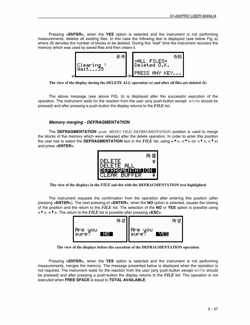
VI-400PRO USER MANUA
5 - 47
Pressing <ENTER>, when the YES option is selected and the instrument is not performing
measurements, deletes all existing files. In this case the following text is displayed (see below Fig. a) where 35 denotes the number of blocks to be deleted. During this “wait” time the instrument recovers the memory which was used by saved files and then clears it.
a) (b)
The view of the display during the DELETE ALL operation (a) and after all files are deleted (b)
The above message (see above FIG. b) is displayed after the successful execution of the operation. The instrument waits for the reaction from the user (any push-button except <Altf> should be pressed) and after pressing a push-button the display returns to the FILE list.
Memory merging - DEFRAGMENTATION The DEFRAGMENTATION (path: MENU/ FILE/ DEFREGMENTATION) position is used to merge
the blocks of the memory which were released after the delete operation. In order to enter this position the user has to select the DEFRAGMENTATION text in the FILE list, using <5555>, <6666> (or <3333>, <4444>) and press <ENTER>.
The view of the displays in the FILE sub-list with the DEFRAGMENTATION text highlighted The instrument requests the confirmation from the operation after entering this position (after
pressing <ENTER>). The next pressing of <ENTER>, when the NO option is selected, causes the closing of the position and the return to the FILE list. The selection of the NO or YES option is possible using <3333>, <4444>. The return to the FILE list is possible after pressing <ESC>.
The view of the displays before the execution of the DEFRAGMENTATION operation Pressing <ENTER>, when the YES option is selected and the instrument is not performing
measurements, merges the memory. The message presented below is displayed when the operation is not required. The instrument waits for the reaction from the user (any push-button except <Altf> should be pressed) and after pressing a push-button the display returns to the FILE list. The operation is not executed when FREE SPACE is equal to TOTAL AVAILABLE.

VI-400PRO USER MANUAL
5 - 48
The view of the display in the case when the DEFRAGMENTATION operation is not required
When the DEFRAGMENTATION operation is performed, the following texts are displayed (see Fig. a and b below).
The view of the displays during the execution of the DEFRAGMENTATION operation
During this “wait” time the instrument recovers the memory which was used by deleted files, clears it and merges in one block. The message presented below is displayed after successful memory merging (see Fig. c below). The instrument waits for the reaction from the user (any push-button except <Altf> should be pressed) and after pressing a push-button the display returns to the FILE list. The result of the DEFRAGMENTATION operation appears (see Fig. c below), while the state of the memory before the execution of this operation is given in Fig. a (below).
a) b) c)
The view of the displays with the state of the file’s memory (a), after completing the DEFRAGMENTATION operation (b) and the state of the memory after the successful execution of the operation (c)
Removing all files with results from buffer’s memory - CLEAR BUFFER The CLEAR BUFFER (path: MENU / FILE / CLEAR BUFFER) position is used to delete the whole
contents of the buffer’s memory of the instrument (all files are erased). It is not possible to leave any data in the buffer. In order to enter this position the user has to select (highlight) the CLEAR BUFFER text in the FILE list, using <5555>, <6666> (or <3333>, <4444>) and press <ENTER>.
The view of the displays in the FILE sub-list with the CLEAR BUFFER text highlighted

VI-400PRO USER MANUA
5 - 49
The instrument requests the confirmation of the operation after entering this position (after pressing <ENTER>). The next pressing of <ENTER>, when the NO option is selected, causes the closing of the position and the return to the FILE list. The selection of the NO or YES option is possible using <3333>, <4444>. The return to the FILE list is possible after pressing <ESC>.
The view of the displays during the execution of the CLEAR BUFFER operation
After pressing <ENTER> the instrument checks its current state. When measurements are being
performed, the execution of the CLEAR BUFFER operation is not possible. In such case the message with the changing case letters is displayed (see below) and the instrument returns after few seconds to the list from which the CLEAR BUFFER position was called.
The view of the displays with the message stating the reason the requested operation is not possible
The instrument returns to the FILE list after the successful completion of the CLEAR BUFFER operation.
Checking the contents of the memory - CATALOGUE The CATALOGUE position is used for checking the contents of the memory (the list of the files). In
order to enter this position the user has to select (highlight) the CATALOGUE text in the FILE list, using <5555>, <6666> (or <3333>, <4444>) and press <ENTER>.
The view of the displays in the FILE sub-list with the CATALOGUE text highlighted
When the instrument memory is empty (no file is stored), after entering the CATALOGUE position, the NO FILES text is displayed and the instrument waits for the reaction from the user. The user should then press <ESC>, <ENTER> or <START / STOP>.

VI-400PRO USER MANUAL
5 - 50
The same information, as in the LOAD position, about the existing files in the instrument are displayed after opening CATALOGUE position. In the consecutive lines of the display the current file number, the total number of the files, the file name, the file type, date and time of registration are presented. The change of the current file with the unit step can be done pressing <3333>, <4444>. After pressing <SHIFT> with <3333> the first file is available and after pressing <SHIFT> with <4444> the last one is displayed. The return to the FILE list is possible after pressing <ESC> or <ENTER>.
The view of the displays during the execution of the CATALOGUE operation
Checking the free space in the memory - FREE SPACE The FREE SPACE (path: MENU / FILE / FREE SPACE) position is used to read out the free space in
the FLASH DISC memory of the instrument. In order to enter this position the user has to select (highlight) the FREE SPACE text in the FILE list, using <5555>, <6666> (or <3333>, <4444>) and press <ENTER>.
The view of the displays in the FILE sub-list with the FREE SPACE text highlighted
The number of available space depends on the memory option installed in the unit and the history of the measurements. The position is closed and the instrument returns to the FILE list after pressing <ENTER>, or <ESC> or after starting / contining the measurements (using the <PROCEED> or <START / STOP> push-buttons).
a) b) The view of the displays during the execution of the FREE SPACE operation in the units with 8 MB (a)
and 32 MB of internal memory (b)

VI-400PRO USER MANUA
5 - 51
Saving setup in the instrument’s memory – SAVE SETUP and SAVE NEXT SETUP The SAVE SETUP (path: MENU / FILE / SAVE SETUP) position is used for storing data in the
FLASH DISC memory of the instrument as a file (file formats are available upon request). In order to enter this position the user has to select (highlight) the SAVE text in the FILE list, using <5555> (or <3333>). After the selection <ENTER> must be pressed. The additional function for saving a setup (the SAVE NEXT – save a setup with the name increased by one) is available after pressing <3333>, <4444>.
The view of the displays in the FILE sub-list with the SAVE SETUP text highlighted
The additional function for saving a setup (the SAVE NEXT – save a setup with the name increased by one) is available after pressing <3333>, <4444>. The return to the FILE sub-list is possible after pressing <ESC>.
The view of the displays with the SAVE SETUP position opened
The name of the setup file, in which the configuration of meter is saved, is displayed under the
SAVE or SAVE NEXT text. The default name for a setup file is displayed when this position is first entered (after power on) and the last saved setup file’s name is displayed when this position is next entered. It is possible to edit this name in two ways: full and simplified.
The window of the full editing of the setup file’s name (the FILE NAME) is opened after pressing <ENTER> when the SAVE function was selected for saving measurement results.
The user can skip the full edition of the setup file’s name pressing once more the <ENTER> push-button. This will result in the passing to the phase of the setup file’s saving description just after the FILE NAME window.
The view of the displays during the process of setting the character in the edited name
One can select the proper position of the character in the edited text using <3333>, <4444>. The available ASCII characters can be changed using <5555>, <6666>. The subsequent upper case letters, digits, space and underline appear on the display in the highlighted position after each pressing of the mentioned above push-buttons.
The empty space is created for the introduction of a new character in the edited name (the INS operation is executed) when <Altf > and <4444> are pressed together .

VI-400PRO USER MANUAL
5 - 52
The view of the displays in the FILE NAME editing after pressing <Altf> and <4444> .
The character, which is highlighted, is deleted from the edited name (the Del operation is executed) when <Altf> and <3333> are pressed together.
The view of the displays in the FILE NAME edition after pressing <Altf> and <3333> .
The edited name is accepted and the file is saved after pressing <ENTER> (see the description of the SAVE NEXT function). The instrument then waits for a reaction from the user (any push-button except <Altf> should be pressed). All changes introduced to the file name during the editing are ignored after pressing <ESC>. This pressing causes the return to the list from which the SAVE SETUP option was entered.
The simplified edition adds a natural number to the end of the file name. The increase by one number is achieved by each pressing of <Altf> with <4444> and the decrease by each pressing of <Altf> with <3333>. The number can be changed from 0 to N, with the only limitation of the N value being the length of the file name, which cannot exceed 8 characters in length.
The view of the displays in the simplified edition of the file name
The SAVE position is displayed once more after about 3 seconds. The message presented below is displayed after pressing <ENTER> when the file of the selected name already exists in the instrument’s memory. The instrument then waits for the reaction from the user (any push-button except <Altf> should be pressed) and after pressing a push-button the display returns to the SAVE position.
The view of the displays after the SAVE operation when the file with the selected name already exists in the instrument’s memory

VI-400PRO USER MANUA
5 - 53
The setup is saved in the file with the name increased by one number at the end of the SAVE NEXT text after pressing <ENTER> (if the instrument is not measuring and there is a setup to be stored).
Notice: In the SAVE NEXT function it is possible to save a setup file bypressing <ENTER>, skipping the full or simplified edition of the file’s name.
The following message containing the name of the file and the operation performed is displayed during the setup file’s saving:
The view of the display during the execution of the SAVE SETUP operation
Another message is displayed after successfully saving the setup file in the memory and then the instrument waits for the reaction from the user (any push-button except <Altf>should be pressed) and after pressing a push-button the display returns to the FILE list. The assumptive setup file’s name is displayed after repeated enter to the SAVE position of the FILE list (after pressing <ENTER>).
a) b) c)
The displays with the SAVE NEXT function (a); after saving the setup file with the increased name (b) and after repeated <ENTER> to the SAVE NEXT function (c)
It is not possible to store the data in the file, which already exists, when the REPLACE position is
not active ([ ]). The presented below message is displayed after pressing the <ENTER> push-button in the case when during the name edition process the user selected the name which was used before. The instrument then waits for the reaction of the user (any push-button should be pressed except the <Altf> one) and after pressing a push-button it returns to the FILE list.
a) b)
The displays after the file’s name selection (a) and with the message if the REPLACE position is not active (b)
Loading the files with the configuration – LOAD SETUP The LOAD SETUP (path: MENU/ FILE/ LOAD SETUP) position is used for loading a data file from
the FLASH DISC. The position is opened after pressing <ENTER> when the LOAD SETUP text in the FILE list is (highlighted) selected using <5555>, <6666> (or <3333>, <4444>). The return to the FILE list is possible after pressing <ESC>.

VI-400PRO USER MANUAL
5 - 54
The view of the displays in the FILE sub-list with the LOAD SETUP text highlighted
Notice: It is not possible to load the file during the execution of the measurements. On such attempt the message: „measurement in progress / MEASUREMENT IN PROGRESS” is displayed for about 2 seconds.
After pressing <ENTER> the instrument checks its current state. When measurements are performed the file loading is not possible. In such case the message with the changing case letters is displayed (see below) and the instrument returns after few seconds to the list from which the LOAD position was called.
The view of the displays with the message stating the reason the requested operation is not possible When the instrument memory is empty (no file is stored), after entering the LOAD SETUP position
the NO FILES text is displayed and the instrument waits for the reaction from the user. The user should then press <ESC>, <ENTER> or <START / STOP>.
The view of the displays during the execution of the LOAD SETUP operation
The current number of the file and the total number of the saved files is displayed in the first line.
The name of the file is highlighted in the second line (its current number is presented in the first line). The SETUP type of the current file is given in the third line. Date and time of the SAVE operation is displayed in the fourth line. The change of the current file with the unit step can be done after pressing <3333>, <4444>. After pressing <Altf> with <3333> the first file is available and after pressing <Altf> with <4444> the last file is displayed.
The view of the displays during the overview of the file list

VI-400PRO USER MANUA
5 - 55
The name of the file is accepted and the file is loaded after pressing <ENTER>. The message is displayed with the name of the selected file during the execution of the operation i.e.:
The view of the display during the execution of the LOAD operation
The next message is displayed after successfully loading the file. The instrument waits for the reaction from the user (any push-button except <Altf> should be pressed) and after pressing a push-button the display returns to the FILE list.
The view of the displays after the execution of the LOAD operation

VI-400PRO USER MANUAL
5 - 56
Operations in buffer
The buffer is the selected part of the instrument’s memory dedicated for storing the huge number of the measurement results.The buffer operation is strongly dependent on the operation mode of the instrument (the selected function).
Notice: The new file in the buffer is created after each start of the new measurement. The contents of the buffer (all registered files) are erased after execution the CLEAR BUFFER operation from the FILE list. It is not possible to erase only one or a few selected files from the buffer!
1. In the Sound Level Meter mode selected results from each of four channels can be logged in the buffer’s file with the time step defined in the BUF. STEP position. If the value set in this position is equal to 1 sec, thus for three profile results logging the buffer is fulfilled after 168 hours (or 7 days) of the continuous work. If the results from only one profile are saved the buffer will be filled after 500 hours (21 days) of work!
EXAMPLE 1. Assuming that the following settings are selected:
MEASURE SETUP sub-list INT. TIME: 10 m, REP. CYCLE: 1, BUF. STEP: 1 s, BUFFERS SETUP sub-list CHANNEL 1: BUFFERS: PEAK, CHANNEL 2: BUFFERS: RMS, CHANNEL 3: BUFFERS: None. CHANNEL 4: BUFFERS: None
Then after 10 minutes (the value set in INT. TIME position) and after one measurement cycle (the value set in the REP. CYCLE position) the current file in the buffer will contain 600 PEAK values from channel 1 and 600 one second RMS values (one second set in the BUF. STEP position) from channel 2. EXAMPLE 2. Assuming that the instrument set-up is as follows:
MEASURE SETUP sub-list INT. TIME: 1 m, REP. CYCLE: 1, BUF. STEP: 7 s, BUFFERS SETUP sub-list CHANNEL 1: BUFFERS: PEAK, CHANNEL 2: BUFFERS: RMS, CHANNEL 3: BUFFERS: None. CHANNEL 4: BUFFERS: None.
Then after the end of the measurement the current file in the buffer will contain 8 PEAK values (for each 7-second period set in the BUF. STEP position) from channel 1 and 8 RMS values from channel 2.
Notice: Setting BUFFER: OFF in a profile will result in bypassing the registration of the measurement results from this profile in the current file in the buffer. In the same time it will create more space in the buffer for the results from other profiles (independent instruments)!
2. In 1/1 OCTAVE or 1/3 OCTAVE analysis one selected result from each of three profiles together with
the spectra can be logged in the current file of the buffer with the step selected in the BUF. STEP position.

VI-400PRO USER MANUA
5 - 57
EXAMPLE 3. To force the spectra to be logged every second in a file of the buffer without the results measured in three profiles the user has to set:
MEASURE SETUP sub-list INT. TIME: <any value>, REP. CYCLE: <any value>, BUF. STEP: 1 s, BUFFERS SETUP sub-list CHANNEL 1: BUFFERS: None, CHANNEL 2: BUFFERS: None, CHANNEL 3: BUFFERS: None. SPECTRUM: BUFFER: RMS, FILE list SAVE OPTIONS: AUTO SAVE [√√√√].

VI-400PRO USER MANUAL
5 - 58
5.4. CALCULATION OF THE DOSE PARAMETERS - AUX. FUNCTIONS
In order to open the AUX. FUNCTIONS list the user has to: • press <MENU>, • select (highlight) the AUX. FUNCTIONS text from the main list, using <5555>, <6666> (or <3333>, <4444>) , • press <ENTER>.
Pressing <Altf> and <5555> (or <Altf> and <3333>) results in a movement to the first position of the opened list and pressing <Altf> and <6666> (or <Altf> and <4444>) results in a movement to the last position of the opened list.
The view of the display in the main list; the AUX. FUNCTIONS text highlighted
The AUX. FUNCTIONS list is used to calculate the various parameters which are mainly dedicated for the control of the VIBRATION. In the internal firmware version 2.17 this sub-list contains only one position: HAV/WBV CALC. The HAV/WBV CALCULATOR (path: MENU / AUX. FUNCTIONS / HAV/WBV CALC. / HAV CALCULATOR or WBV CALCULATOR) position is used to calculate the characteristics parameters for these measurements. It enables the VI-400Pro to calculate the HAV and WBV value, PARTIAL EXPOSURE and DAILY EXPOSURE.
The following items are presented on the HAV/WBV CALC. list:
HAV CALCULATOR enables the VI-400Pro to calculate the various H–A parameters; WBV CALCULATOR enables the VI-400Pro to calculate the various WB parameters.
In order to confirm the selection <ENTER> has to be pressed. After this confirmation the opened window or list is closed. In order to ignore any changes made in the opened window or list the user has to press <ESC>.
The view of the displays with the HAV CALCULATOR list Selection of the calculation results - HAV CALCULATOR The HAV CALCULATOR (path: MENU / AUX. FUNCTIONS / HAV/WBV CALC. / HAV CALCULATOR)
position is used to calculate the various H–A parameters which are mainly dedicated for the control of the vibration dose. There values calculated are: the PARTIAL EAV/ELV, PARTIAL EXPOSURE and DAILY EXPOSURE of vibration. All results are counted according to the standard selected in the STANDARD position (path: SETUP/ HAV/WBV DOSE/ STANDARDS). In order to enter this sub-list the user has to select (highlight) the HAV CALCULATOR text in the HAV/WBV CALC. list, using <5555>, <6666> (or <3333>, <4444>) and press <ENTER>. The selection of a parameter which level has to be set is done using <5555>, <6666>.
This function is available only in VLM mode.

VI-400PRO USER MANUA
5 - 59
In the HAV CALCULATOR list the following items are available:
RESULTS SEL. position which enables the user to select files with measurement’s results with H-A data;
PARTIAL EAV/ELV position which displays the partial result of dose;
PARTIAL EXP. position which displays the result of exposure;
DAILY EXPOSURE position which displays the result of daily exposure.
The user can select available positions from the main list, using <5555>, <6666> (or <3333>, <4444>), the display text is highlighted. In order to confirm the selection <ENTER> has to be pressed. After this confirmation the opened window or list is closed. In order to ignore any changes made in the opened window or list the user has to press <ESC>.
The view of the displays with the HAV CALCULATOR sub-list
Selection of the file with result of measurement - RESULT SEL. The RESULT SEL. position (path: MENU / AUX. FUNCTIONS / HAV/WBV CALC. / HAV
CALCULATOR / RESULTS SEL.) is used to load data file from the FLASH DISC. The user selects which files of measurement should be used to determine results of measurements. It is possible to select 6 files, which include measurement’s results with H–A data. The position is opened after pressing <ENTER> when the RESULTS SEL. text in the HAV CALCULATOR list is selected (highlighted) using <5555>, <6666> (or <3333>, <4444>). The return to the AUX. FUNCTIONS list is possible after pressing <ESC>.
The view of the display in the HAV CALCULATOR sub-list the RESULT SEL text highlighted
After pressing <ENTER> the position is closed and the instrument opens a new sub-list. It consists of six positions. The user can review the list using <5555>, <6666> (or <3333>, <4444>) and select a position after pressing <ENTER>.
The view of the display in the RESULTS SEL. list

VI-400PRO USER MANUAL
5 - 60
In order to enter the file the user has to select a position using <5555>, <6666> (or <3333>, <4444>) and press <ENTER>.
The view of the displays during the execution of the selected file operation The current file is displayed in the first line. The name of the file is highlighted in the second line.
The change of the current file with the unit step can be done after pressing <3333>, <4444>. After pressing <Altf> with <3333> the first file is available and after pressing <Altf> with the last one is displayed.
The name of the file is accepted and the file is loaded after pressing <ENTER>. The name of this file appears in a list:
a) b) c)
The view of the display with the selecting file (a) and after the execution of the operation (b), (c)
The figure in the brackets on the right side of the RESULTS SEL. indicates the number of selected files.
The message is displayed when the selected file does not include H–A data. The instrument waits for the reaction from the user till any push-button <Altf> is pressed. After that the display returns to the RESULTS SEL. list.
The view of the displays after the execution of the operation
The view of the displays during the execution of the setting the EXPOSURE TIME operation
The EXPOSURE TIME position defines the time during which measurement results are extrapolated. The required parameter can be set using <3333>, <4444> and confirmed by <ENTER>. The integration time (EXPOSURE TIME) can be set (from 00h00m to 24h00m with 1m step by pressing <3333>, <4444> or with 30m step by pressing <Altf> with <3333>, <4444>). The user can set the EXPOSURE TIME for each file separately.

VI-400PRO USER MANUA
5 - 61
Selection of the partial results - PARTIAL EAV/ELV The PARTIAL EAV/ELV position (path: MENU / AUX. FUNCTIONS / HAV/WBV CALC. /
HAV CALCULATOR / PARTIAL EAV/ELV) is used to display partial results, for each file separately. The results are displayed in two columns – the first column for EAV results and the second for ELV results. The position is opened after pressing <ENTER> when the PARTIAL EAV/ELV text, in the HAV CALCULATOR sub-list, is selected (highlighted) using <5555>, <6666> (or <3333>, <4444>). The return to the HAV CALCULATOR sub-list is possible after pressing <ESC>.
The view of the display in the HAV CALCULATOR sub-list the PARTIAL EAV/ELV text highlighted
a) b) c)
The view of the display with the empty partial result list (a), the selecting file in RESULT SEL. sub-list (b) and the PARTIAL EAV/ELV results for selecting file (b), (c)
The user can review the RESULTS SEL. sub-list and PARTIAL EAV/ELV list using <5555>, <6666>. The return to the HAV CALCULATOR sub-list is possible after pressing <ESC>.
The view of the display with the selected file in RESULT SEL. sub-list and the PARTIAL EAV/ELV results for select file
Selection of the partial exposure - PARTIAL EXP. The PARTIAL EXP. position (path: MENU / AUX. FUNCTIONS / HAV/WBV CALC. /
HAV CALCULATOR / PARTIAL EXP.) is used to display EXPOSURE results, for each selected file separately. The results are displayed in one column, there are six positions for each file separately. The position is opened after pressing <ENTER> when the PARTIAL EXP. Text, in the HAV CALCULATOR sub-list, is selected (highlighted) using <5555>, <6666> (or <3333>, <4444>). The return to the HAV CALCULATOR sub-list is possible after pressing <ESC>.
The view of the display in the HAV CALCULATOR sub-list the PARTIAL EXP. text highlighted

VI-400PRO USER MANUAL
5 - 62
The user can review the EXPOSURE list and EAV/ELV list using <5555>, <6666>. The return to the HAV CALCULATOR sub-list is possible after pressing <ESC>.
The view of the display with the EXPOSURE and EAV/ELV results for selected file
Selection of the daily exposure - DAILY EXPOSURE
The DAILY EXPOSURE. position (path: MENU / AUX. FUNCTIONS / HAV/WBV CALC. / HAV CALCULATOR / DAILY EXPOSURE) is used to display DAILY EXPOSURE results, for each selected file separately. The result is counted relatively to EXPOSURE TIME. The position is opened after pressing <ENTER> when the DAILY EXPOSURE text, in the HAV CALCULATOR list, is selected (highlighted) using <5555>, <6666> (or <3333>, <4444>). The return to the HAV CALCULATOR sub-list is possible after pressing <ESC>.
The view of the display in the HAV CALCULATOR sub-list the DAILY EXPOSURE. text highlighted
The view of the display with the DAILY EXPOSURE result for selecting file Selection of the calculation results - WBV CALCULATOR
The WBV CALCULATOR position (path: MENU / AUX. FUNCTIONS / HAV/WBV CALC. / WBV CALCULATOR) is available in VLM mode and used to calculate the various WBV parameters. It enables the user to analyse results based on data saved in files. There are calculated the PARTIAL EAV/ELV, PARTIAL EXPOSURE, DAILY EXPOSURE and DAILY DOSE of vibration. All results are calculated according to the standard selected in STANDARD position (path: SETUP / HAV/WBV DOSE / STANDARDS).
In order to enter this sub-list the user has to select (highlight) the WBV CALCULATOR text in the HAV/WBV CALC. list using <5555>, <6666> (or <3333>, <4444>) and press <ENTER>. The selection of a parameter which level has to be set is done by means of <5555>, <6666>.
In the WBV CALCULATOR sub-list the following items are available: RESULTS SEL. position which enables the user to select files with measurement’s results; PARTIAL EAV/ELV position which displays the partial result of dose; PARTIAL RESULTS position which displays the result of partial exposure;

VI-400PRO USER MANUA
5 - 63
DAILY RESULTS position which displays the results of daily exposure and daily dose.
The user can select (highlight) an available position from the main list, using <5555>, <6666> (or <3333>, <4444>). In order to confirm the selection <ENTER> has to be pressed. After this confirmation the opened window or list is closed. In order to ignore any changes made in the opened window or list the user has to press <ESC>.
The view of the displays with the WBV CALCULATOR list
Selection of the file with result of measurement - RESULT SEL. The RESULT SEL. position (path: MENU / AUX. FUNCTIONS / HAV/WBV CALC. /
WBV CALCULATOR / RESULTS SEL.) is used to load a data file from the FLASH DISC. User selects which files of measurement should be used to determine results of measurements. It is possible to select at most 6 files, which include measurement’s results with WBV data. The position is opened after pressing <ENTER> when the RESULTS SEL. text in the WBV CALCULATOR list is selected (highlighted) using <5555>, <6666> (or <3333>, <4444>). The return to the AUX. FUNCTIONS list is possible after pressing <ESC>.
The view of the display in the WBV CALCULATOR sub-list the RESULT SEL text highlighted
After pressing <ENTER> the position is closed and the instrument opens a new sub-list, consisting of six positions. The user can review the list using <5555>, <6666> (or <3333>, <4444>) and select the position after pressing <ENTER>.
The view of the display in the RESULTS SEL. list
In order to enter the file the user has to select (highlight) a position using <5555>, <6666> (or <3333>, <4444>) and press <ENTER>.
The view of the displays during the execution of the selected file operation

VI-400PRO USER MANUAL
5 - 64
The current file is displayed in the first line. The name of the file is highlighted in the second line. The change of the current file with the unit step is done pressing <3333>, <4444>. After pressing <Altf> with <3333> the first file is available and after pressing <Altf> with <4444> the last file is displayed.
The name of the file is accepted and the file is loaded after pressing <ENTER>. The name of this file appears in a list:
a) b) c)
The view of the display with the select file (a) and after the execution of the operation (b), (c)
The figure in the brackets on the right side of the RESULTS SEL. indicates the number of selected files.
The message below is displayed when the selected file does not include WBV data. After pressing any push-button except <Altf> the display returns to the RESULTS SEL. sub-list.
The view of the displays after the execution of loading a file without WBV data
The view of the displays during the execution of the setting the EXPOSURE TIME operation
The EXPOSURE TIME position defines the time for the extrapolation of measurement results. The required parameters can be set using <3333>, <4444> and confirmed by pressing <ENTER>. The integration time (EXPOSURE TIME) can be chosen from 00h00m to 24h00m in 1m step by pressing <3333>, <4444> or in 30m step by pressing <Altf> with <3333>, <4444>. The user can set the EXPOSURE TIME for each file separately.
Selection of the partial results - PARTIAL EAV/ELV The PARTIAL EAV/ELV position (path: MENU / AUX. FUNCTIONS / HAV/WBV CALC. /
WBV CALCULATOR / PARTIAL EAV/ELV) is used to display partial results, for each file separately. The results are displayed in two columns – the first column for EAV results and the second for ELV results. The position is opened after pressing <ENTER> when the PARTIAL EAV/ELV text in the WBV CALCULATOR sub-list is selected (highlighted) using <5555>, <6666> (or <3333>, <4444>). The return to the WBV CALCULATOR sub-list is possible after pressing <ESC>.

VI-400PRO USER MANUA
5 - 65
The view of the display in the WBV CALCULATOR sub-list the PARTIAL EAV/ELV text highlighted
a) b) c)
The view of the display with the empty partial result list (a), the selecting file in RESULT SEL. sub-list (b) and the PARTIAL EAV/ELV results for selecting file (b), (c)
The user can review the RESULTS SEL. sub-list and PARTIAL EAV/ELV list using <5555>, <6666>. The return to the WBV CALCULATOR sub-list is possible after pressing <ESC>.
The view of the display with the selecting file in RESULT SEL. sub-list and the PARTIAL EAV/ELV results for selecting file
Selection of the partial results - PARTIAL RESULTS The PARTIAL RESULTS position (path: MENU / AUX. FUNCTIONS / HAV/WBV CALC. /
HAV CALCULATOR / PARTIAL RESULTS) is used to display PARTIAL EXPOSURE results. The results are displayed in one column and represented by six positions for each file separately. The position is opened after pressing <ENTER> when the PARTIAL EXP. text in the WBV CALCULATOR sub-list is selected (highlighted) using <5555>, <6666> (or <3333>, <4444>). The return to the WBV CALCULATOR sub-list is possible after pressing <ESC>.
The view of the display in the WBV CALCULATOR sub-list the PARTIAL RESULTS. text highlighted
The user can review the PARTIAL EXP. sub-list and EAV/ELV list using <5555>, <6666>. The return to the WBV CALCULATOR sub-list is possible after pressing <ESC>.
The view of the display with the PARTIAL EXPOSURE and EAV/ELV results for selected file

VI-400PRO USER MANUAL
5 - 66
Selection of the daily result - DAILY RESULTS
The DAILY RESULTS. position (path: MENU / AUX. FUNCTIONS / HAV/WBV CALC. / WBV CALCULATOR / DAILY EXPOSURE) is used to display DAILY EXPOSURE and DAILY DOSE results, for each selected file separately. The result is calculated relatively to EXPOSURE TIME. The position is opened after pressing <ENTER> when the DAILY RESULTS text in the WBV CALCULATOR sub-list is selected (highlighted) using <5555>, <6666> (or <3333>, <4444>). The return to the WBV CALCULATOR sub-list is possible after pressing <ESC>.
The view of the display in the WBV CALCULATOR sub-list; the DAILY RESULTS. text highlighted
The view of the display with the DAILY EXPOSURE and DAILY DOSE results for selecting file

VI-400Pro User Manual
C - 1
APPENDIX C - DATA SPECIFICATIONS
C.1. SPECIFICATION OF VI-400Pro AS SOUND LEVEL METER/ ANALYZER
The VI-400Pro instrument working as the SLM meets requirements of the IEC 651, IEC 804 and IEC 61672-1 for the Type 1 instruments.
System configuration:
VI-400Pro, 59-523 BK4936 ½” Class 1 microphone, 072-028 Microphone Pre-Amplifier – for connecting 59-523 microphone to 4th input channel, QC-20 Acoustic calibrator (or equivalent). Measuring ranges for the LEQ values:
RANGE Measurement range (with the error < 0.7 dB) (LEQ for the sinusoidal signal and microphone sensitivity 50 mV/Pa)
105 dB from 24 dB “A” -weighting to 115 dB “A” -weighting
105 dB from 24 dB “C” -weighting to 115 dB “C” -weighting
105 dB from 30 dB “LIN” -weighting to 115 dB “LIN” -weighting
130 dB from 44 dB “A” -weighting to 137 dB “A” -weighting
130 dB from 42 dB “C” -weighting to 137 dB “C” -weighting
130 dB from 46 dB “LIN” -weighting to 137 dB “LIN” -weighting
Measuring range for the PEAK value:
Measurement range PEAK (for the microphone sensitivity 50 mV/Pa)
RANGE Max PEAK value
105 dB 118 dB “A” -weighting
105 dB 118 dB “C” -weighting
105 dB 118 dB “LIN” -weighting
130 dB 140 dB “A” -weighting
130 dB 140 dB “C” -weighting
130 dB 140 dB “LIN” -weighting
Notice: For the signals with the crest factor n >1.41 upper measuring range of the RMS (LEQ and SPL) is reduced. The valid upper limit can be calculated according to the below given formula:
An = 137 − 20 log (n )[m], where A is the upper limit for the sinusoidal signal Example: For the crest factor
n =10 the upper limit is A10
= 120 dB
Measuring frequency range of the acoustic pressure (- 3 dB): 10 Hz to 20 000 Hz. Basic measurement error of the acoustic pressure: < 0.7 dB(measured for the reference conditions, see below).

VI-400Pro User Manual
C - 2
Weighting filters (see appendix D): • LIN meeting requirements of the IEC 61672-1 standard for the Type 1 “Z“ filter, •A meeting requirements of the IEC 651 and IEC 61672-1 standard for the Type 1 “A” filter, •C meeting requirements of the IEC 651 and IEC 61672-1 standard for the Type 1 “C” filter, RMS detector: • Digital: “True RMS“ with PEAK detection, • Resolution: 0.1 dB, • Range: 999.9 dB, • Crest Factor: unlimited (for signals in 20 kHz band). Time weighting characteristics: • “S“(SLOW) according to IEC 651 Type 1, • “F“(FAST) according to IEC 651 Type 1, • “I” (IMPULSE) according to IEC 651 Type 1. Primary indicator range (IEC 651) from 24 dB to 137 dB (with “A” -weighting).
Linearity range (IEC 804) from 24 dB to 137 dB (with “A” -weighting).
Pulse range (IEC 804) from 24 dB to 140 dB (with “A” -weighting).
Reference conditions:
• Type of the acoustic field: free, • Reference acoustic pressure: 114.0 dB (related to 20 µPa), • Reference frequency: 1000 Hz, • Reference temperature: +20°C, • Reference relative humidity: 65 %, • Reference static pressure: 1013 hPa,
• Reference incidence direction: perpendicular to the microphone diaphragm.
Calibration:Acoustical -with the QC-20 acoustic calibrator (or equivalent), Calibration level 114.0 dB.
Warm-up time: 1 min. (for 0.1 dB accuracy).
Effect of humidity: < 0.5 dB (for 30 % < RH < 90 % at 40°C & 1000 Hz).
Effect of magnetic filed: < 15 dB (A) or < 25 dB (LIN) (for 80 A/m and 50 Hz).
Effect of temperature: < 0.5 dB (from -10°C to + 50°C), Operating range – from -10°C to + 50°C, Storage – from -20°C to + 60°C.
Effect of Vibration:< 71 dB (from 20 Hz to 1000 Hz at 1 m/s2
).
Additional functions: Overload indication, Underrange indication, Battery state indication.

VI-400Pro User Manual
C - 3
C.2. SPECIFICATION OF VI-400Pro AS 1/1 OCTAVE, 1/3 OCTAVE AND FFT SOUND
ANALYZER
The VI-400Pro instrument as 1/1 OCTAVE or 1/3 OCTAVE sound analyzer conforms to the international standards (IEC 651, IEC 61672-1 and IEC 804) for type 1 sound level meters and the IEC 1260 standard for the pass band filters.
Configuration of the system:
• VI-400Pro, 59-523 BK4936 ½” Class 1 Pre-Polarized Microphone, 072-028 Microphone Pre-Amplifer, for connecting 59-523 microphone to 4th input. QC-20 acoustic calibrator: or equivalent. Measuring ranges:
Two measuring ranges “105 dB” and "130 dB"
RANGE Measurement range (with the error < 0.7 dB) (LEQ for the sinusoidal signal and microphone sensitivity 50 mV/Pa)
105 dB from 24 dB “A” -weighting to 115 dB “A” -weighting
105 dB from 24 dB “C” -weighting to 115 dB “C” -weighting
105 dB from 30 dB “LIN” -weighting to 115 dB “LIN” -weighting
130 dB from 44 dB “A” -weighting to 137 dB “A” -weighting
130 dB from 42 dB “C” -weighting to 137 dB ”C” -weighting
130 dB from 46 dB “LIN” -weighting to 137 dB “LIN” -weighting
Measurement range PEAK (for the microphone sensitivity 50 mV/Pa)
RANGE Max PEAK value
105 dB 118 dB “A” -weighting
105 dB 118 dB “C” -weighting
105 dB 118 dB “LIN” -weighting
130 dB 140 dB “A” -weighting
130 dB 140 dB “C” -weighting
130 dB 140 dB “LIN” -weighting
Notice: For the signals with the crest factor n >1.41 upper measuring range of the RMS (LEQ and SPL) is reduced. The valid upper limit can be calculated according to the below given formula:
An = 137 − 20 log (n ), where A is the upper limit for the sinusoidal signal Example: For the crest factor
n =10 the upper limit is A10
= 120 dB

VI-400Pro User Manual
C - 4
Measuring frequency range of the acoustic pressure with the HP filter (-3 dB): 10 Hz to 20 000 Hz. Basic measurement error of the acoustic pressure: < 0.7 dB (measured for the reference conditions, see below). Weighting filters (see appendix D): • LIN meeting requirements of the IEC 61672-1 standard for the Type 1 “Z“ filter, • A meeting requirements of the IEC 651 and IEC 61672-1 standard for the Type 1 “A” filter, • C meeting requirements of the IEC 651 and IEC 61672-1 standard for the Type 1 “C” filter, RMS detector: • Digital: “True RMS“ with PEAK detection, • Resolution: 0.1 dB, • Range: 999.9 dB, • Crest Factor: unlimited (for signals in 20 kHz band). Time weighting characteristics: • “S“ (SLOW) according to IEC 651 Type 1, • “F“(FAST) according to IEC 651 Type 1, • “I”(IMPULSE) according to IEC 651 Type 1. Primary indicator range (IEC 651) from 44 dB to 120 dB (with “A” -weighting). (for 130 dB reference range) Linearity range (IEC 804) from 44 dB to 137 dB (with “A” -weighting). (for 130 dB reference range) Pulse range (IEC 804) from 44 dB to 140 dB (with “A” -weighting). (for 130 dB reference range) Reference conditions: • Type of the acoustic field free, • Reference acoustic pressure: 94.0 dB (related to 20 µPa), • Reference frequency: 1000 Hz, • Reference temperature: +20°C , • Reference relative humidity: 65 %, • Reference static pressure: 1.013 kPa, • Reference incidence direction: perpendicular to the microphone diaphragm. Calibration: Acoustical with the QC-20 acoustic calibrator or equivalent, Calibration level 114.0 dB, Warm-up time: 1 min. (for 0.1 dB accuracy). Effect of humidity: < 0.5 dB (for 30 % < RH < 90 % at 40°C & 1000 Hz). Effect of magnetic field: < 15 dB (A) or < 25 dB (LIN) (for 80 A/m and 50 Hz). Effect of temperature: < 0.5 dB (from -10°C to + 50°C), Operating range – from -10°C to + 50°C, Storage – from -20°C to + 60°C.
Effect of Vibration: < 71 dB (from 20 Hz to 1000 Hz at 1 m/s2
). Additional functions: Overload indication, Underrange indication, Battery state indication. Noise levels (measured with the microphone equivalent impedance 18 pF): • ”LIN” weighting < 11 µVRMS, • ”A” weighting < 6 µVRMS, • ”C” weighting < 6 µVRMS.

VI-400Pro User Manual
C - 5
Antialiasing filter: Built-in antialiasing filter ensuring correct sampling of the measured signal. Sampling frequency: 51.2 kHz (internal only). Analog to digital converter: 2 x 20 bit. Reference range: 130 dB. Input attenuator accuracy (for f = 1 kHz and T = +23°C): 0.1 dB. Internal oscillator accuracy (for f = 1 kHz and T = +23°C): 0.01 %. Digital Filters (see Appendix D) High pass filter HP: high pass filter for 1/1 OCTAVE and 1/3 OCTAVE analysis. High pass filter LIN: cut-off frequency 27.0 Hz / -0.1 dB (10.0 Hz / -3.0 dB), pass-band ripple < 0.1 dB, roll-off 6 dB / octave. 1/1 OCTAVE: 15 filters with center frequencies from 1 Hz to 16 kHz (base 2), meeting DIN 45651, IEC 1260 (Annex B) and ANSI S1.11-1986 for Type 1. 1/3 OCTAVE: 45 filters with center frequencies from 0.8 Hz to 20 kHz (base 2), meeting DIN 45651, IEC 1260 (Annex B) and ANSI S1.11-1986 for Type 1.

VI-400Pro User Manual
C - 6
C.3. SPECIFICATIONS OF VI-400Pro AS VIBRATION LEVEL METER / ANALYZER System Configuration: • VI-400Pro • 072-026 Tri-Axial HAV accelerometer System conforms to the ISO 8041, ISO 2631-1, ISO 5349 and ISO 10816 standards. Measurement ranges for the acceleration: 2 ranges with the nominal values: 17.8 ms-2, 316 ms-2 (145 dB, 170 dB related to 10
-6 ms -2).
Values of the measured acceleration: • linear measurement (with the HP1 filter): the measurement ranges for the distance from noise > 6 dB from 0.003 ms-2 to 596 ms-2 (the sinusoidal signal RMS), from 0.03 ms-2 to 798 ms-2 (PEAK),
RANGE (RMS) Measurement ranges
17.8 ms-2 (145.0 dB) from 3.16 mms-2 (70.0 dB) to 56.2 ms-2 (155.0 dB)
316 ms-2 (170.0 dB) from 33 mms-2 (90.0 dB) to 1000 ms-2 (180.0 dB)
• linear measurement (with the HP3 filter): the measurement ranges for the distance from noise > 6 dB from 0.001 ms-2 to 596 ms-2 (the sinusoidal signal RMS), from 0.01 ms-2 to 798 ms-2 (PEAK),
RANGE (RMS) Measurement ranges
17.8 ms-2 (145.0 dB) from 1 mms-2 (60.0 dB) to 56.2 ms-2 (155.0 dB)
316 ms-2 (170.0 dB) from 10 mms-2 (80.0 dB) to 1000 ms-2 (180.0 dB)
• linear measurement (with the HP10 filter): the measurement ranges for the distance from noise > 6 dB from 0.0003 ms-2 to 596 ms-2 (the sinusoidal signal RMS), from 0.003 ms-2 to 798 ms-2 (PEAK),
RANGE (RMS) Measurement ranges
17.8 ms-2 (145.0 dB) from 0.5 mms-2 (54.0 dB) to 56.2 ms-2 (155.0 dB)
316 ms-2 (170.0 dB) from 10 mms-2 (80.0 dB) to 1000 ms-2 (180.0 dB)
Notice: In the measurement of the signal with the crest factor n > 1.41 the upper measurement range for the RMS value is reduced. Its value can be calculated from the equation:
An =A +10 -20log (n / ) [m], where A is the given range for the sinusoidal signal.
E.g. for n = 10 and A = 140 the value of A10
is equal to = 133 dB.
Notice: In the measurement conditions with the strong electromagnetic disturbances (e.g. near the high-voltage transmission lines) the lower measurement limit can be drastically shifted as the result of the external field influence on the measurement cables. In such cases the careful shielding of the measurement cables is strongly recommended. It is worth to underline that the estimation of the external influence can be performed in-site by the observations of the measurement signal spectrum.

VI-400Pro User Manual
C - 7
Frequency range for the acceleration measurement (+/-10%): 0.5 Hz ÷ 5 kHz in the linear measurements with the HP1 filter. Notice: With the application of another vibration transducer the frequency range given above for the HP1 filter can be different (wider). Basic error for the acceleration measurement: < ± 0.7 dB. Instrument's pre-heating time: 1 minute. Measurement channels calibration: Direct: by the measurement of the standard signal generated by the external vibration calibrator, Digital: by the declaration of the transducer's sensitivity. Accelerometer inputs: Connectors: 1 x LEMO ENB.0B.304 CLM pin (plus 1 x TNC for auxiliary transducer), Impedance (each channel): 40 k / 100 pF (typical), Vibration transducers powering: 28 V / 2.5 mA current source, Range of the measured voltage: Lower level -filter depended (see below); Upper level -7.5 VRMS (137 dB
related to 1 µVRMS or 177 dB related to 1 µm/s2
RMS). Internal noise level: Wideband noise level measured with the voltage input short-circuit (20 kHz band): • with the HP1 filter: < 17 µVRMS (see appendix D.2 for the filter characteristics); • with the HP3 filter: < 17 µVRMS (see appendix D.2 for the filter characteristics); • with the HP10 filter: < 17 µVRMS (see appendix D.2 for the filter characteristics); • with the W–Bxy filter: < 3 µVRMS (see appendix D.2 for the filter characteristics); • with the W–Bz filter: < 3 µVRMS (see appendix D.2 for the filter characteristics); • with the H–A filter: < 3 µVRMS (see appendix D.2 for the filter characteristics); • with the W–Bc filter: < 3 µVRMS (see appendix D.2 for the filter characteristics); • with the KB filter: < 85 µVRMS (see appendix D.2 for the filter characteristics); • with the Wk filter: < 3 µVRMS (see appendix D.2 for the filter characteristics); • with the Wd filter: < 3 µVRMS (see appendix D.2 for the filter characteristics); • with the Wc filter: < 3 µVRMS (see appendix D.2 for the filter characteristics); • with the Wj filter: < 3 µVRMS (see appendix D.2 for the filter characteristics); • with the VelMF filter: < 3 µVRMS (see appendix D.2 for the filter characteristic). Maximum input voltage: The VI-400Pro is the instrument with the 2
nd
security class according to the international standard IEC 348. The input voltage should be within the range from 0 V to 28 V. Crosstalk between channels: <80 dB @ 1 kHz. Overload detection: The instrument has the built-in overload detectors. The overload in each of four measurement channels (in analog part) and in their analog-to-digital converters are independently detected. Antialiasing filters: Pass band (-1 dB): 24.2 kHz, Stop band : 27.1 kHz, Attenuation in the stop band: > 70 dB. Sampling frequency: internal -51.2 kHz. Analog/Digital conversion: 2x20 bits resolution. Total linearity error: from 0 dB to 90 dB below the full scale < ± 0.5 dB (170 dB range with the HP10 filter). Reference range: 170 dB. Level indication range: from -100 dB to +10.2 dB related to the nominal range level.

VI-400Pro User Manual
C - 8
Basic accuracy: < ± 0.2 dB for the temperature T=+23°C ± 5°C for sinusoidal signal 140 dB RMS in the band 10 Hz ÷ 20 kHz with the HP10 input filter. Measurement error in the full temperature range: < ± 0.3 dB when the temperature is from -10°C to +50°C for the sinusoidal signal 140 dB RMS in the band 10 Hz ÷ 20 kHz with the HP10 input filter. Input divider accuracy: ± 0.1 dB. Amplitude indication stability: ± 0.1 dB. Accuracy and stability of the frequency indication: 0.01 %. Digital filters Low-pass filters: 8 eighth-order elliptic filters with the cut-off frequencies from 10 kHz to 78.125 Hz in the binary sequence. Ripple in the pass band: ± 0.1 dB. Attenuation in the stop band: > 100 dB. High-pass filters (only for the vibration level meter):HP1 filter (see appendix D.2 for the filter characteristics).HP3 filter (see appendix D.2 for the filter characteristics).HP10 filter (see appendix D.2 for the filter characteristics). 1/1 OCTAVE filters: 15 sixth-order elliptic filters with the center frequencies from 1 Hz to 16 kHz conforming to the DIN 45651, IEC 1260 (Type 1) and ANSI S1.11-1986 standards. 1/3 OCTAVE filters: 45 sixth-order elliptic filters with the center frequencies from 0.8 Hz to 20 kHz conforming to the DIN 45651, IEC 1260 (Type 1) and ANSI S1.11-1986 standards. Weighting filters (only for the vibration level meter): • W–Bxy from 1 Hz to 330 Hz; with 6 dB / octave slope (cf. App. D.2 for the filter characteristics). • W–Bz from 3 Hz to 1000 Hz; with 6 dB / octave slope (cf. App. D.2 for the filter characteristics). • H–A from 1 Hz to 330 Hz; with 6 dB / octave slope (cf. App. D.2 for the filter characteristics). • W–Bc from 3 Hz to 1000 Hz; with 6 dB / octave slope (cf. App. D.2 for the filter characteristics). • KB from 10 Hz to 3000 Hz; with 6 dB / octave slope (cf. App. D.2 for the filter characteristics). • Wk from 1 Hz to 18 Hz; with 12 dB / octave slope (cf. App. D.2 for the filter characteristics). • Wd from 1 Hz to 18 Hz; with 12 dB / octave slope (cf. App. D.2 for the filter characteristics). • Wc from 3 Hz to 57 Hz; with 12 dB / octave slope (cf. App. D.2 for the filter characteristics). • Wj from 10 Hz to 181 Hz; with 12 dB / octave slope (cf. App. D.2 for the filter characteristics). Special filter: Filter for the evaluation of the state of machines: VelMF: 10 Hz to 1000 Hz; conforms to the ISO 10816 standard (see appendix D.2 for the filter characteristic). RMS detector: Digital with 0.1 dB sampling step. PEAK and P–P detectors: Digital with 0.1 dB sampling step.

VI-400Pro User Manual
C - 9
C4. MISCELLANEOUS SPECIFICATION OF VI-400Pro Display: Graphical, the liquid crystals (LCD) type with the backlight, 97x32 pixels and icons. Memory: 32 MB flash memory and 96 kB of the RAM memory. Flash memory divided between: buffer for the registration of the time history and spectra (about 60 % of the installed memory), FLASH-disk for storing the measurement data files (about 30 % of the installed memory). Signal input (Channel 4): The input of the measured signal (taken from the microphone preamplifier or the vibration transducer):
TNC connector (external view)
Pin number TNC
Central Input
Shield Ground
Signal input (Channels 1 -3): The input of the measured signal (taken from the microphone preamplifiers or the vibration transducers):
LEMO type ENB.OB.304 compatible socket (external view)
Pin number ENB.OB.304
1 Input for channel 1
2 Input for channel 2
3 Input for channel 3
4 Signal ground for channels 1 -3
Shield Ground connected to pin number 4

VI-400Pro User Manual
C - 10
Power supply (Ext. Power): Instrument is dedicated for the operation from the internal replaceable battery. Instrument autonomy is operating mode depending. Power consumption from 6 V source is as follows: Meter Mode -<160mA@6V (at+20°C) ANALYZER Mode -<200mA@6V (at +20°C) Typical operating time from 4 x AA alkaline batteries ensures will be about 10 hours and 8 hours respectively. For the temperatures below 0°C operating time can decrees (depending on the batteries). Instrument can be also powered from the external source (e.g. SA 17A or car battery) with the DC Voltage from 6 V to 24 V connected to Ext. Power socket. The red-color indicator, named as EXT. POWER and placed on the bottom of instrument’s keyboard, should light after connecting the external power source to the instrument. Voltage ripple should not exceed ± 5%. Power requirement is voltage dependent: Meter Mode -<70mA@12V (at+20°C) ANALYZERMode -<100mA@12V (at+20°C) Meter Mode -<40mA@24V (at+20°C) ANALYZER Mode -<60mA@24V (at +20°C)
Power Supply connector 5.5 / 2.1 mm (external view)
Internal Pin 5.5 / 2.1
Shield Ground
1 + 6 V ÷ 24 V
Instrument can be also powered from the USB port of a PC, however following conditions and limitations should be considered: • Till the internal battery voltage is higher than approx. 4.6 V, the instrument operates from internal battery, • When the internal battery voltage decreases below 4.6 V and the USB is connected to a PC, the instrument switches to operate from the USB (that is indicated by the removal of the "Battery" icon from the display), • current capability of the USB port should be as high as 300 mA, in the case of battery-powered PCs this additional current requirement should be considered by the user, • when an external power supply (e.g. SA 17A or car battery) is connected to Ext. Power terminal no supply current is drawn from the USB, as well as from internal battery.

VI-400Pro User Manual
C - 11
EXT I/O & AC Out (AC / Int) User programmable Input / Output connector AC Out (Analog Output) -standardized output of the measured input signal from user-programmable one of four channels (no weightings)
LEMO type ERN.00.250 compatible socket (external view)
Pin Number ERN.00.250
1 Output/Input
Shield Ground
Chassis Ground Socket: LEMO type ERN.00.250 compatible Output Voltage: 0.2 VRMS (± 5 %) at input level 105 dB (dB related to 1 µV) for 105 dB range 0.2 VRMS (± 5 %) at input level 130 dB (dB related to 1 µV) for 130 dB range Frequency Band (-3 dB) -0.6 Hz ÷ 22.6 kHz Output impedance: 51 / 1% EXT I/O (External Input/Output) -digital Input / Output pin -3.3 V input & output levels. Below the electrical characteristic of AC / Int. socket in the VI-400Pro unit is described more precisely. 1. If the instrument is switched off, the AC / Int. is in the active state as the input ready to switch on the instrument (cf. the requirements for the switching signal stated in 3.1 below). 2. If the instrument is switched on three possibilities are available selected by the user from the menu (set as the default after switching on the unit): a) AC as standardised output of the measured signal; one from four channels selected by the user, b) Int. as Input (SLAVE mode) used for the external triggering of the instrument (the parameters of the triggering signal are stated in 3.2 below), c) Int. as Output (MASTER mode) used for the external instruments triggering (the parameters of the signal of the external triggering is stated in 3.3 below). 3. Specification of the external signals: 3.1. The signal for switching on the instrument (cf. point 1); the voltage impulse with the parameters given below: a) Recommended voltage range is +/-12 V (abs. max +/-15 V; the TRANSIL type internal limit of the absolute voltage higher than 15 V). If necessary higher voltage can be used, even up to 30 V, but in that case a serial resistor (from 5 kOhm to 10 kOhm) should be connected with the source of trigger signal. b) Triggering level +1 V. c) Triggering slope -uprising. d) Minimal duration of the triggering signal -100 msec. (it means that the input signal higher than +1 V threshold has to be kept for at least 100 msec.). e) Input impedance -ca. 10 kOhm / 100pF, ESD type safety. 3.2. The SLAVE input signal (cf.point 2); the instrument receives the voltage impulse having the parameters given below: a) Voltage range, level, impedance as in 3.1; it is not recommended to use the voltage higher than +/-12 V (+/-1 V), additional serial resistances are not recommended either. b) Minimal duration of the triggering impulse: 10 µseconds. c) The triggering is done on the slope (falling or rising) of the triggering signal set by the user by passing through +1 V threshold. d) Next triggering is possible after 100 µsec. from the end of the previous measurement.

VI-400Pro User Manual
C - 12
3.3. The MASTER output signal (cf. point 3); for trigger control; the instrument operates as a trigger signal source, output impulse with the parameters given below: a) Voltage: 0 V or 3 V. b) Triggering slope: uprising or falling down set by the user in the menu. c) Input impedance: 50 Ohm. d) Duration of the impulse: ca. 10 µsec. Interface USB 1.1 It meets USB 1.1 requirements and enables remote control of the instrument and data transfer up to attainable with 12 MHz clock.
USB socket (external view)
Pin number USB
1 Vbus
2 D
3 D+
4 GND
Shield Ground
Real Time Clock: Built-in real time clock. Accuracy better than 1 minute / month. Weight with the battery: 520 g (without accelerometer, cable and microphone preamplifier). Dimensions: 44x84x145 mm (without accelerometer, cable and microphone preamplifier). Electromagnetic Compatibility The product described above is in conformity with: 1. 89/336/EEC EMC Directive of 03 May 1989 amended by 92/31/EEC Directive of 22 April 1992 and 93/68/EEC Directive of 22 July 1993, and 2. 72/23/EEC Low Voltage Directive of 19 February 1973 amended by 93/68/EEC Directive of 22 July 1993. Notice: EMC compatibility is guarantied only with the original accessories supplied by QUEST- TECHNOLOGIES ! Safety: Instrument meets EN 61010-1.2001 "Safety requirements for electrical equipment for measurement, control and laboratory use -Part 1: General requirements". Environmental parameters: • Operating temperature range: -10°C ÷ +50°C. • Storage temperature range: -20°C ÷ +60°C. • Humidity: 90% RH in 30°C (non-condensing).

VI-400Pro USER MANUAL .
D - 1
The MAX result The MAX result, saved in the buffer’s file, is calculated according to the formula:
( )( )tpmaxMAX WTb=
The MAX main result is calculated according to the formula:
( )( ) secfor 1tpmaxMAX WT ≠= ττττ
The MTVV result The Maximum Transient Vibration Value - MTVV, saved as the main result, is defined (according to
the ISO 8041 standard) as:
( )( ) secfor 1tpmaxMTVV WT == ττττ
The RMS result The RMS result is calculated according to the formula:
( )2
1
0
2
= ∫
T
W dttrT1
RMS
For the RMS result saved in the files of the buffer (time history) T = Tb.
The VDV result The fourth power vibration dose value (VDV) expressed in meters per second taken to the power of
1.75 (m/s1.75) is calculated from the formula:
( )4
1T
0
4W dttrVDV
= ∫
This result is calculated in the case when the Human Vibration Option is available.
The VEC result The vector result is calculated from the formula:
∑=
=4
1i
2i
2i RMSKVEC
where:
iK – coefficient for channel i. For channels not selected for vector calculation, iK equals to zero.
iRMS – the RMS value from channel i.

VI-400Pro USER MANUAL.
D - 2
D.1.2. Definitions of the Hand-Arm vibration results available in the vibration mode of the VI-400Pro Symbol definitions
2z
2y
2x RMSRMSRMSAEQ ++=
T0 - Reference duration of 28 800 seconds (8 hours) TE - Exposure time T - Measurement time EAV - Exposure Action Value ELV - Exposure Limit Value
The Current Exposure result The Current Exposure result is calculated according to the formula:
0TT
AEQCExp =
The Daily Exposure result The Daily Exposure result is calculated according to the formula:
0
E
TT
AEQ)8(A =
The EAV Total Time result The EAV Total Time result is calculated according to the formula:
2
0TT AEQEAV
TEAV
=
The EAV Time Left Result The EAV Time Left result is calculated according to the formula:
TEAVEAV TTTL −=
The ELV Total Time result The ELV Total Time result is calculated according to the formula:
2
0TT AEQELV
TELV
=
The ELV Time Left Result The ELV Time Left result is calculated according to the formula:
TELVELV TTTL −=

VI-400Pro USER MANUAL .
D - 3
D.1.3. Definitions of the Whole-Body vibration results available in the vibration mode of the VI-400Pro Symbol definitions
{ }zyxWB VDV,VDV4.1,VDV4.1maxVDV =
{ }zyxWB RMS,RMS4.1,RMS4.1maxRMS =
T0 - Reference duration of 28 800 seconds (8 hours) TE - Exposure time T - Measurement time
EAVA - Exposure Action Value expressed in 2s
m
ELVA - Exposure Limit Value expressed in 2s
m
EAVV - Exposure Action Value expressed in 75.1s
m
ELVV - Exposure Limit Value expressed in 75.1s
m
The Current Exposure result The Current Exposure result is calculated according to the formula:
0WB T
TRMSCExp =
The Daily Exposure result The Daily Exposure result is calculated according to the formula:
0
EWB T
TRMS)8(A =
The Current Dose result The Current Dose result is calculated according to the formula:
WBVDVCDose =
The Daily Dose result The Daily Dose result is calculated according to the formula:
4 EWB T
TVDVDDose =

VI-400Pro USER MANUAL.
D - 4
The EAV Total Time result The EAV Total Time result is calculated according to the formula:
2
WB
A0TTA RMS
EAVTEAV
=
4
WB
VTTV VDV
EAVTEAV
=
=
75.1TTV
2TTA
TT
sm
in islimit EAV if EAV
sm
in islimit EAV if EAVEAV
The EAV Time Left Result The EAV Time Left result is calculated according to the formula:
TEAVEAV TTTL −=
The ELV Total Time result The ELV Total Time result is calculated according to the formula:
2
WB
A0TTA RMS
ELVTELV
=
4
WB
VTTV VDV
ELVTELV
=
=
75.1TTV
2TTA
TT
sm
in islimit ELV if ELV
sm
in islimit ELV if ELVELV
The ELV Time Left Result The ELV Time Left result is calculated according to the formula:
TELVELV TTTL −=

VI-400Pro USER MANUAL .
D - 5
D.1.4. Definitions of the results available in the sound mode of the VI-400Pro The PEAK result
The PEAK result (Peak Sound Pressure or Peak Sound Level) is calculated for the given T from the formula:
( )( )0WT ptamaxlog20PEAK =
For the PEAK result saved in the files of the buffer (time history) T = Tb.
The SPL result
The SPL result (Sound Pressure Level) - gives an equivalent of the Sound Level Meter according to the IEC 651 Standard (meeting the requirements for the Type "1" instrument). The value of the SPL result is calculated from the formula:
( )( )( )0WT ptpmaxlog20SPL1
= where:
T1 - the last second of the measurement.
The MAX result The MAX result means the maximal value on the detector output for the integration time period.
The MAX result for the time period of 1 second is equal to the value of the SPL function. The MAX result is calculated according to the formula:
( )( )( )0WT ptpmaxlog20MAX =
For the MAX result saved in the files of the buffer (time history) T = Tb.
The MIN result The MIN result is calculated according to the formula:
( )( )( )0WT ptpminlog20MIN =
For the MIN result saved in the files of the buffer (time history) T = Tb.
The LEQ result The LEQ result means the RMS value of sound pressure in the given time period. The instrument
operates as the standard Integrating Sound Level Meter and conforms to the IEC 804 Standard (meeting the requirements for the Type 1 instrument). The value of the LEQ result is calculated from the formula:
( )( )2
1
0
20
= ∫
T
W dtptrT1
log20LEQ

VI-400Pro USER MANUAL.
D - 6
The RMS result The RMS result, saved in the buffer’s file, is calculated according to the formula of the LEQ. The
value of the RMS result is calculated from the formula:
( )( )2
1
0
20
= ∫
bT
Wb
dtptrT1
log20RMS
The SEL result The SEL result (Sound Exposure Level) is essentially the subset of the LEQ result. Its value is
equal to the LEQ result referred to the integration time equal to one second (so, for the INT. TIME=1 s, SEL is always equal to LEQ). The value of the SEL is calculated from the formula:
( )( )2
1
0
20
= ∫
T
W dtptrlog20SEL
The Ltm3 and Ltm5 results The Ltm3 and Ltm5 results (Takt-Maximal Levels) are calculated according to the German
standard TA Larm.
The Ld, Le, Ln, Lde, Len, Lnd and Lden results Only one from the mentioned above results is available in the instrument. It depends on the day
and night time in which the measurement was performed. It is assumed that: • the day-time (denoted as Td) starts from 7 am and ends at 7 pm, • the evening-time (denoted as Te) starts from 7 pm and ends at 11 pm, • the night-time (denoted as Tn) starts at 11 pm and ends at 7 am.
The mentioned above results are calculated from the following expressions:
( )( )2
1
20
= ∫
dTW
d
dtptrT1
log20Ld (Td ≠ 0, Te = 0, Tn = 0),
( )( )2
1
20
+= ∫
eTW
e
dtptrT1
log20dB5Le (Td = 0, Te ≠ 0, Tn = 0),
( )( )2
1
20
+= ∫
nT
Wn
dtptrT1
log20dB10Ln (Td = 0, Te = 0, Tn ≠ 0),
( )
⋅+⋅+
= 10Le10Ld 1041012412
1log10Lde (Td ≠ 0, Te ≠ 0, Tn = 0),
( )
⋅+⋅+
= 10Ln10Le 10810484
1log10Len (Td = 0, Te ≠ 0, Tn ≠ 0),

VI-400Pro USER MANUAL .
D - 7
( )
⋅+⋅+
= 10Ld10Ln 1012108128
1log10Lnd (Td ≠ 0, Te = 0, Tn ≠ 0),
( )
⋅+⋅+⋅++
= 10Ln10Le10Ld 10810410124812
1log10Lden (Td ≠ 0, Te ≠ 0, Tn ≠ 0).

VI-400Pro USER MANUAL.
D - 8
D.2. CHARACTERISTICS OF DIGITAL FILTERS IMPLEMENTED IN VI-400Pro
The digital weighting filters implemented in the SLM mode
HP: cut-off frequency: 0,770 Hz / -0,1 dB (0,225 Hz / -3,0 dB).
Characteristics of the HP filter implemented in the VI-400Pro instrument in the SLM mode
LIN: cut-off frequency: 27.0 Hz / -0.1 dB (10.0 Hz / -3.0 dB).
Characteristics of the LIN filter implemented in the VI-400Pro instrument in the SLM mode

VI-400Pro USER MANUAL .
D - 9
A type 1 according to IEC 651 standard.
Characteristics of the A filter implemented in the VI-400Pro instrument in the SLM mode
C type 1 according to IEC 651 standard.
Characteristics of the C filter implemented in the VI-400Pro instrument in the SLM mode

VI-400Pro USER MANUAL.
D - 10
The digital weighting filters implemented in the VLM mode
The HP1 filter is used for the vibration measurements (the acceleration signal) in the frequency range from 1 Hz to 20 kHz.
Characteristics of the HP1 digital filter implemented in the VI-400Proinstrument in the VLM mode for the acceleration measurements
The HP3 filter is used for the vibration measurements (the acceleration signal) in the frequency range from 3.5 Hz to 20 kHz.
The characteristics of the HP3 digital filter implemented in the VI-400Pro instrument in the VLM mode for the acceleration measurements

VI-400Pro USER MANUAL .
D - 11
The HP10 filter is used for the vibration measurements (the acceleration signal) in the frequency range from 10 Hz to 20 kHz.
The characteristics of the HP10 digital filter implemented in the VI-400Pro instrument in the VLM mode for the acceleration measurements
The digital filters implemented in the vibration level meter (VLM) mode for the velocity measurements
The characteristics of the Vel1 digital filter implemented in the VI-400Pro instrument in the VLM mode for the velocity measurements

VI-400Pro USER MANUAL.
D - 12
The characteristics of the Vel3 digital filter implemented in the VI-400Pro instrument in the VLM mode for the velocity measurements
The characteristics of the Vel10 digital filter implemented in the VI-400Pro instrument in the VLM mode for the velocity measurements

VI-400Pro USER MANUAL .
D - 13
The VelMF filter is used for the evaluation of the state of the machines. This filter is used for the measurements in the frequency range from 10 Hz to 1000 Hz and conforms to the ISO 10816 standard.
The characteristics of the VelMF digital filter implemented in the VI-400Pro instrument in the VLM mode for the velocity measurements
The digital filters implemented in the vibration level meter (VLM) mode for the displacement measurements
The characteristics of the Dil1 digital filter implemented in the VI-400Pro instrument in the VLM mode for the displacement measurements

VI-400Pro USER MANUAL.
D - 14
The characteristics of the Dil3 digital filter implemented in the VI-400Pro instrument in the VLM mode for the displacement measurements
The characteristics of the Dil10 digital filter implemented in the VI-400Pro instrument in the VLM mode for the displacement measurements

VI-400Pro USER MANUAL .
D - 15
The digital filters included in the HUMAN VIBRATION OPTION
The W–Bxy filter is used for the assessment of the influence of the vibration signal on the human body in the horizontal direction. It conforms to the ISO 2631 and ISO 8041 (version dated as 1990-07-15) standards.
The characteristics of the W-Bxy digital filter implemented in the VI-400Pro instrument in the VLM mode
The W–Bz filter is used for the assessment of the influence of the vibration signal on the human body in the vertical direction. It conforms to the ISO 2631 and ISO 8041 (version dated as 1990-07-15) standards.
The characteristics of the W-Bz digital filter implemented in the VI-400Pro instrument in the VLM mode

VI-400Pro USER MANUAL.
D - 16
The H–A filter is used for the assessment of the influence of the local vibration signal on the human body. It conforms to the ISO 2631 and ISO 8041 (version dated as 1990-07-15) standards.
The characteristics of the H-A digital filter implemented in the VI-400Pro instrument in the VLM mode
The W–Bc filter is used for the assessment of the influence of the vibration signal on the human body during the seat-back measurements. It conforms to the ISO 2631 and ISO 8041 (version dated as 1990-07-15) standards.
The characteristics of the W-Bc digital filter implemented in the VI-400Pro instrument in the VLM mode

VI-400Pro USER MANUAL .
D - 17
The KB filter is used for the vibration measurements on ships. Its characteristics, presented below, is taken from the formulae: KB = W–Bc +28.9 dB.
The characteristics of the KB digital filter implemented in the VI-400Pro instrument in the VLM mode
The Wk filter is used for the assessment of the influence of the vibration signal on the human body in the z direction and for vertical recumbent direction. It conforms to the ISO 2631-1-97 and ISO 8041 (version dated as 1999-11-01) standards.
The characteristics of the Wk digital filter implemented in the VI-400Pro instrument in the VLM mode

VI-400Pro USER MANUAL.
D - 18
The Wd filter is used for the assessment of the influence of the vibration signal on the human body in the x and y directions and for horizontal recumbent direction. It conforms to the ISO 2631-1-97 and ISO 8041 (version dated as 1999-11-01) standards.
The characteristics of the Wd digital filter implemented in the VI-400Pro instrument in the VLM mode
The Wc filter is used for the assessment of the influence of the vibration signal on the human body during the seat-back measurements. It conforms to the ISO 2631-1-97 and ISO 8041 (version dated as 1999-11-01) standards.
The characteristics of the Wc digital filter implemented in the VI-400Pro instrument in the VLM mode

VI-400Pro USER MANUAL .
D - 19
The Wj filter is used for the assessment of the influence of the vibration signal under the head of the recumbent person. It conforms to the ISO 2631-1-97 and ISO 8041 (version dated as 1999-11-01) standards.
The characteristics of the Wj digital filter implemented in the VI-400Pro instrument in the VLM mode The digital HP filter implemented in 1/1 OCTAVE, 1/3 OCTAVE and FFT analysis in
the VI-400Pro instrument
The characteristics of the HP digital filter implemented in the VI-400Pro instrument in 1/1 OCTAVE,
1/3 OCTAVE and FFT analysis

VI-400Pro USER MANUAL.
D - 20
The digital 1/1 OCTAVE and 1/3 OCTAVE filters implemented in the VI-400Pro instrument
The characteristics of the exemplary digital 1/1 octave filter implemented in the VI-400Pro instrument

VI-400Pro USER MANUAL .
D - 21
The characteristics of the exemplary lower digital 1/3 octave filter implemented in the VI-400Pro instrument
The characteristics of the exemplary middle digital 1/3 octave filter implemented in the VI-400Pro instrument
The characteristics of the exemplary upper digital 1/3 octave filter implemented in the VI-400Pro instrument

VI-400Pro USER MANUAL.
D - 22

INDEX OF LISTS, SUB-LISTS AND POSITIONS
1/1 OCTAVE Selection of 1/1 OCTAVE analysis, position of FUNCTION sub-list 4 - 39
1/3 OCTAVE Selection of 1/3 OCTAVE analysis, position of FUNCTION sub-list 4 - 58
3 PROFILES Measurement results presentation mode (numerical), position of DISPLAY 5 - 2
sub-list ACC Setting the reference level for acceleration measurements, position of
REFERENCE LEVEL sub-list 5 - 27 ANALOG Type of input / output devices, sub-list of EXT. I/O SETUP 5 - 23
AUTO SAVE Controlling of measurement results savings, position of SAVE OPTIONS sub-list 5 - 42 AXIS SETUP Assign axis of accelometer to the number of channels, sub-list of HAV/WBV
DOSE list 5 - 33
BACKLIGHT Setting the backlight parameters, sub-list of DISPLAY list 5 - 14
BATTERY Checking the state of the internal battery, position of DISPLAY list 5 - 12
BRIGHTNESS Setting the brightness of the backlight, position of BRIGHTNESS sub-list 5 - 14 BUF. STEP Setting time between two writings to the buffer’s file, position of
MEASURE SETUP sub-list 4 - 24
BUFFER VIEW Selection of the buffer’s file to the screen presentation, sub-list of DISPLAY list 5 - 8 BUFFER Selection of 1/1 OCTAVE analysis result to be saved in the buffer’s file, position
of SPECTRUM sub-list 4 - 47 BUFFER Selection of 1/3 OCTAVE analysis result to be saved in the buffer’s file,
position of SPECTRUM sub-list 4 - 78 BUFFERS Selection of the result to be saved in the buffer’s file, position of BUFFERS
SETUP sub-list 4 - 30
CAL. LEVEL Setting the level of the calibrator’s signal, position of CALIBRATION sub-list 4 - 6
CALIBRATION Calibration of sound measurement channel, sub-list of FUNCTION list 4 - 3
CATALOGUE Controlling the contents of the memory, position of FILE list 5 - 49 CHANNEL x Setting parameters in a profile of SLM, sub-list of CHANNELS SETUP sub-list 4 - 25 CHANNELS SETUP Setting parameters in profiles and for octave analysis, sub-list of INPUT list 4 - 24 CLEAR SETUP Return to the factory made settings, position of SETUP list 5 - 25
CLEAR BUFFER Removing all files with the results from buffer’s memory, position of FILE list 5 - 48 CLEAR Clearing the coefficients of the user filters, position of USER FILTER sub-list 5 - 21
CONTRAST Setting the contrast of the screen, position of DISPLAY list 5 - 13 DAILY EXPOSURE Displaying the daily exposure in DOSE mode, sub-list of HAV CALCULATOR
sub-list 5 - 66 DAILY RESULTS Displaying the daily exposure and daily dose in DOSE mode, sub-list of WBV
CALCULATOR sub-list 5 - 66
DEFRAGMENTATION Memory merging, position of FILE list 5 - 47
DELETE ALL Removing all files from instrument’s memory, position of FILE list 5 - 46
DELETE Removing a file with the results from instrument’s memory, position of FILE list 5 - 45 DETECTOR Selection of the RMS detector, position of CHANNEL x sub-list 4 - 29 DIGITAL IN Type of input / output devices, sub-list of EXT. I/O SETUP 5 - 23 DIGITAL OUT Type of input / output devices, sub-list of EXT. I/O SETUP 5 - 23 DIL Setting the reference level for displacement measurements, position of
REFERENCE LEVEL sub-list 5 - 28

DISPLAY MODES Selection of the ways of measurement results presentation, sub-list of 5 - 1 DISPLAY list
DISPLAY SCALE Selection of the scale in graphical results presentations, sub-list of DISPLAY list 5 - 4 DISPLAY Data available on the screen, main list (function of the push-button) 5 - 1 DOSE Selection of DOSE measurements, position of FUNCTION sub-list 5 - 32 DYNAMIC Scaling of the vertical axis of the graphical presentation, position of
DISPLAY SCALE sub-list 5 - 4 EXPOSURE TIME Setting the exposure time, position of HAV/WBV DOSE list 5 - 32 EXT. I/O SETUP Selecting the external devices, sub=list of SETUP list 5 - 23 FIELD CORRECTION Setting the conditions for the diffuse field measurements, position of SETUP list 5 - 18 FILE NAME Edition of the file name in which the measurement results has to be saved 5 - 38 FILE Available operations on files, main list (function of the push-button) 5 - 37 FILTER Selection of the weighting filter, position of CHANNEL x sub-list 4 - 27 FILTER Selection of the weighting filter in 1/1 OCTAVE analysis, position of
SPECTRUM sub-list 4 - 46 FILTER Selection of the weighting filter in 1/3 OCTAVE analysis, position of
SPECTRUM sub-list 4 - 66
FREE SPACE Checking the free space in the memory, position of FILE list 5 - 50
FUNCTION Selection of the unit’s measurement function, main list (function of the) 2 - 2 push-button HAV CALCULATOR Selection of DOSE measurements, position of FUNCTION sub-list 5 - 58 HAV/WBV DOSE Selection of DOSE measurements, position of FUNCTION sub-list 5 - 32
INPUT Measurement parameters setting, main list (function of the push-button) 4 - 22 INT. TIME Setting the integration time, position of MEASURE SETUP sub-list 4 - 23
LEVEL METER Selection of LM function, position of FUNCTION sub-list 4 - 9 LEVEL Selection of the triggering mode, position of TRIGGER SETUP sub-list 4 - 34 LOAD SETUP Loading configuration from the memory with the instruments configuration,
position of FILE list 5 - 53
LOAD Loading file from the memory with the measurements results, position of FILE list 5 - 43
MEASURE FUNCTION Selection of the available measurement function, sub-list of FUNCTION list 4 - 9
MEASURE SETUP Selection of measurement parameters, sub-list of INPUT list 4 - 22 MEASURE SETUP sub-list 4 - 23
MEASURE DOSE Activation of the MEASURE DOSE, sub-list of HAV/WBV DOSE list 5 - 32 PARTIAL EXP. Displaying the partial exposure in DOSE mode, sub-list of HAV CALCULATOR 5 - 61 sub-list
PARTIAL RESULTS Displaying the partial exposure results, sub-list of HAV CALCULATOR sub-list 5 - 65 PARTIAL EAV/ELV Displaying the partial results in DOSE mode, sub-list of HAV CALCULATOR 5 - 61
PLOT Measurement results presentation mode (graphical), position of DISPLAY 5 - 2
MODES sub-list RAM FILE Saving the results of the measurements in the special file at RAM memory,
position of the SAVE OPTIONS list 3 - 10 RANGE Selection of the measurement range in SLM and VLM, position of INPUT list 4 - 26 RANGE Selection of the measurement range in 1/1 OCTAVE analysis, position of
INPUT list 4 - 53 RANGE Selection of the measurement range in 1/3 OCTAVE analysis, position of
INPUT list 4 - 75

REFERENCE LEVEL Setting the reference level for vibration measurements, sub-list of SETUP list 5 - 27 REP. CYCLE Setting number of repetition of measurement cycles, position of
MEASURE SETUP sub-list 4 - 24
REPLACE Replacement of the existing files by the new ones, position of SAVE OPTIONS sub-list 5 - 41
RESULT SEL. Selection the files with H-A data, sub-list of HAV CALCULATOR sub-list 5 - 59 RESULT SEL. Selection the files with WBV data, sub-list of WBV CALCULATOR sub-list 5 - 62 RMS INTEGRATION Selection of detector’s type in the LEQ calculations, position of SETUP list 5 - 26 RTC Programming of the instrument’s internal Real Time Clock, position of RTC 5 - 16
SAVE NEXT Saving files in the memory with the name’s modification, position of FILE list 5 - 38
SAVE NEXT Saving configuration in the memory with the name’s modification, position of 5 - 51
FILE list
SAVE OPTIONS Controlling of the data storing in the instrument’s memory, sub-list of FILE list 5 - 41
SAVE STAT. Controlling of the statistics savings, position of SAVE OPTIONS sub-list 5 - 42
SAVE Saving files in the instrument’s memory, position of FILE list 5 - 38
SAVE Saving the configuration of the instrument in the instrument’s memory, position of FILE SETUP list 5 - 38
SCALE Setting the scale for vibration measurements, position of DISPLAY SCALE 5 - 4 sub-list SETUP Settings of the instrument’s parameters, main list (function of the push-button) 5 - 16 SHIFT MODE Selection of few push-buttons mode, sub-list of SETUP list 5 - 24 SHIFT Selection of the working mode of <SHIFT> push-button, position of 5 - 24 SHIFT MODE sub-list SOURCE Selection of the triggering signal, position of TRIGGER SETUP sub-list 4 - 32
SPECTRUM Measurement results presentation mode (graphical), position of DISPLAY sub-list 5 - 2 SPECTRUM Selection of 1/1 OCTAVE analysis parameters, sub-list of
PROFILES SETUP sub-list 4 - 65 SPECTRUM Selection of 1/3 OCTAVE analysis parameters, sub-list of
PROFILES SETUP sub-list 4 - 77 ST/SP Selection of the working mode of <START / STOP> push-button, position of
SHIFT MODE sub-list 5 - 25 STANDARD Selection of the STANDARD of the measurement of vibration dose, sub-list of
HAV/WBV DOSE list 5 - 34 START DELAY Setting start delay before the start of measurement, position of measure setup 4 - 22
sub-list
STATISTICS Measurement results presentation mode (graphical), position of DISPLAY sub-list 5 - 1 TIMER Programming of the instrument’s internal timer, position of SETUP list 5 - 17 TOTAL VALUE Selection the weighted filter, sub-list of DISPLAY SETUP / CHANNEL x list 5 –5 TRIGGER SETUP Selection of mode and parameters of triggering, sub-list of INPUT list 4 - 32 TRIGGER Switching triggering on and off, position of TRIGGER SETUP sub-list 4 - 32
UNIT LABEL Checking specification of the instrument, position of DISPLAY list 5 - 15
USER FILTERS Introduction of 1/3 octave filter coefficients, sub-list of SETUP list 5 - 19 VECTOR DEFINITION Selecting of the vector coefficient, sub-list of SETUP list 5 - 30 VEL Setting the reference level for velocity measurements, position of
REFERENCE LEVEL sub-list 5 - 27 VIBRATION UNITS Selection of the vibration units, position of SETUP list 5 - 28

WBV CALCULATOR Selection of DOSE measurements, position of FUNCTION sub-list 5 - 62 X-ZOOM Scaling of the horizontal axis of the graphical presentation, position of 5 - 4 DISPLAY SCALE sub-list

WORLDWIDE HEADQUARTERS1060 Corporate Center Drive
Oconomowoc, Wisconsin 53066 USA262-567-9157800-245-0779
www.Quest-Technologies.com
ISO 9001:2000 Registered CompanyISO 17025 Accredited Calibration LabEmployee-Owned Company
072-021Rev. A
11/01/05