real-time ttcn for testing real-time and multimedia systems · real-time ttcn for testing real-time...
TRANSCRIPT

Real-time TTCN for testing real-timeand multimedia systems
Thomas WalterSwiss Federal Institute of Technology Zurich, Computer Engineering andNetworks Laboratory (TIK)CH-8092 Zurich, Switzerland, Tel: +41-1-632 7007, Fax: +41-1-632 1035,e-mail: [email protected]
Jens GrabowskiMedical University of Lübeck, Institute for TelematicsRatzeburger Allee 160, D-23538 Lübeck, Germany, Tel: +49-451-500 3723,Fax: +49-451-500 3722, e-mail: [email protected]
AbstractIn this paper we define real-time TTCN and apply it to several applications. In real-time TTCN, statements are annotated with time labels that specify their earliest andlatest execution times. The syntactical extensions of TTCNare the definition of atable for the specification of time names and time units, and two new columns inthe dynamic behaviour description tables for the annotation of statements with timelabels. We define an operational semantics for real-time TTCN by mapping real-time TTCN to timed transition systems. Alternatively, we introduce a refined TTCNsnapshot semantics that takes time annotations into account.
KeywordsConformance testing, TTCN, test cases, real-time testing

1 INTRODUCTION
Testing, or to be preciseconformance testing, is the generally applied process in val-idating communication software. A conformance testing methodology and frame-work (ISO9646-1 1994) have been established within the standardization bodies ofISO and ITU. An essential part of this methodology is a notation, called TTCN (Treeand Tabular Combined Notation) (ISO9646-3 1996), for the definition of confor-mance test cases. TTCN has been designed for testing systemsfor which in generaltiming between communicating entities has not been an issue. Test cases are speci-fied as sequences of test events which are input and output events of abstract serviceprimitives (ASP) or protocol data units (PDU). The relativeordering of test events isdefined in atest case behaviour description.
The situation is changing now. We can identify two main new kinds of distributedsystems: firstly, real-time systems which stem from the use of computers for con-trolling physical devices and processes. For these systems, real-time communicationis essential for their correct behaviour. Secondly, multimedia systems which involvethe transmission of several continuous streams (of bits) and their timely reproduction(e.g., synchronization of audio and video). However, as pointed out in, e.g., (Atesetal. 1996), TTCN is not an appropriate test notation for testingreal-time and multi-media systems: Firstly, test events in TTCN are for message-based systems and notfor stream-based systems. Secondly, in TTCN real-time can only be approximated.In this paper we define a real-time extension of TTCN as a contribution for solvingthe second problem.
Our extension of TTCN toreal-time TTCNis on a syntactical and a semanticallevel. The syntactical extension is that we allow an annotation of test events withan earliest execution time (E ET) and a latest execution time (L ET). Informally, atest event may be executed if it has been enabled for at leastE ET units and it mustbe executed if it has been enabled forL ET units. For the definition of an opera-tional semantics of real-time TTCN we use timed transition systems (Henzingeretal. 1991).
A number of techniques for the specification of real-time constraints have beenproposed which are besides others: time Petri Nets (Berthmieuet al. 1991, Merlinet al. 1976) and extensions of LOTOS (Bowmanet al. 1994, Hogrefeet al. 1992,Léonardet al. 1994, Quemadaet al. 1987), SDL (Hogrefeet al. 1992, Leue 1995)and ESTELLE (Fischer 1996). As in the cited literature, our approach allows the tim-ing of actions relative to the occurrence of previous actions. The difference betweenthe cited approaches and ours is that real-time TTCN is a hybrid method used forthe specification ofpropertiesof test systems andrequirementson implementationsunder test (IUT).
Section 2 gives a brief introduction to TTCN. Section 3 explains real-time TTCN.The applicability of our approach is shown in Section 4. Section 5 concludes thepaper with an assessment of our work and the discussion of open issues.

2 TTCN - TREE AND TABULAR COMBINED NOTATION
TTCN is a notation for the description of test cases to be usedin conformance testing.For the purpose of this paper we restrict our attention to TTCN concepts related tothe description of the dynamic test case behaviour. Furtherdetails on TTCN can befound in: (Baumgarten and Giessler 1994, Baumgarten and Gattung 1996, ISO9646-3 1996, Kristoffersenet al. 1996, Linn 1989, Probertet al. 1992, Sarikaya 1989).
2.1 Abstract testing methods and TTCN
A test case specifies which outputs from an IUT can be observedand which inputsto an IUT can be controlled. Inputs and outputs are eitherabstract service primi-tives(ASPs) orprotocol data units(PDUs). In general, several concurrently runningdistributedtest components(TC) participate in the execution of a test case. TCs areinterconnected bycoordination points(CPs) through which they asynchronously ex-changecoordination messages(CMs). TCs and IUT logically communicate by ex-changing PDUs which are embedded in ASPs exchanged atpoints of control andobservation(PCOs), which are interfaces above and below the IUT. Since in mostcases the lower boundary of an IUT does not provide adequate PCO interfaces, TCsand IUT communicate by using services of an underlying service provider.
2.2 Test case dynamic behaviour descriptions
The behaviour description of a TC consists ofstatementsandverdict assignments.A verdict assignment is a statement of either PASS, FAIL or INCONCLUSIVE,concerning the conformance of an IUT with respect to the sequence of events whichhas been performed. TTCN statements aretest events(SEND, IMPLICIT SEND,RECEIVE, OTHERWISE, TIMEOUT and DONE),constructs(CREATE, ATTACH,ACTIVATE, RETURN, GOTO and REPEAT) andpseudo events(qualifiers, timeroperations and assignments).
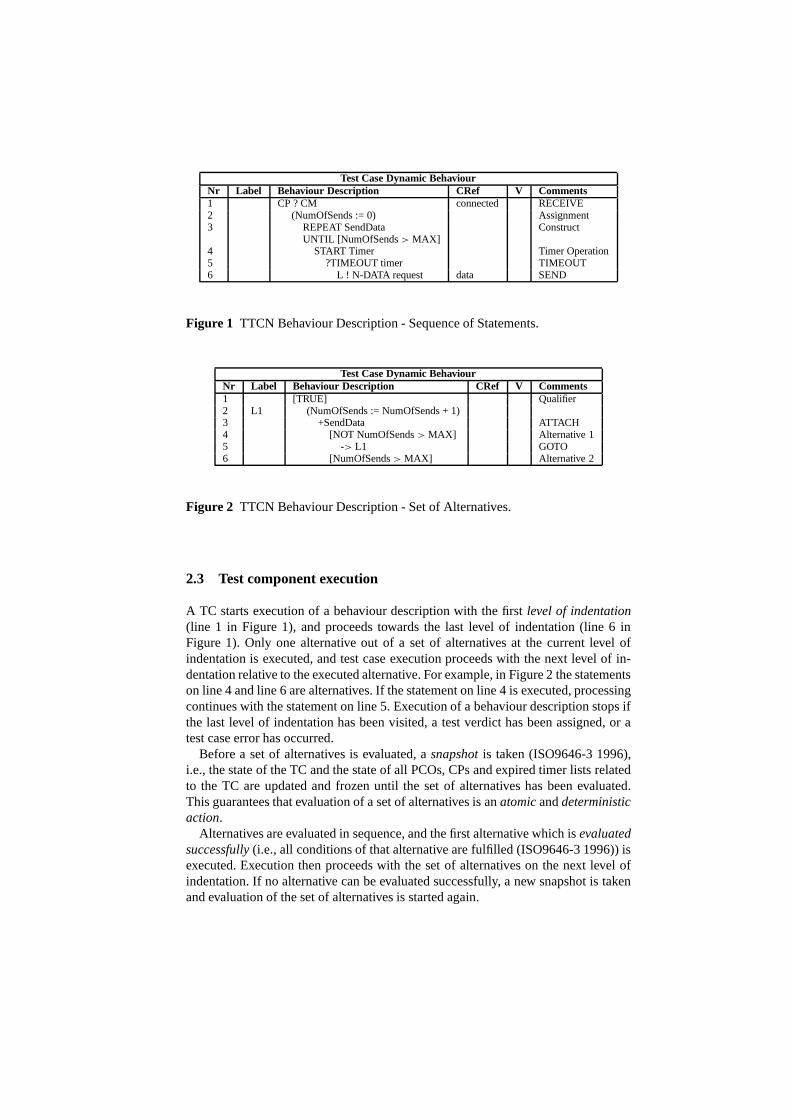
Statements can be grouped intostatement sequencesandsets of alternatives. In thegraphical form of TTCN, sequences of statements are represented one after the otheron separate lines and beingindentedfrom left to right. The statements on lines 1 -6 in Figure 1 are a statement sequence. Statements on the samelevel of indentationand with the same predecessor are alternatives. In Figure 2 the statements on lines 4and 6 are a set of alternatives: they are on the same level of indentation and have thestatement on line 3 as their common predecessor.
Test Case Dynamic BehaviourNr Label Behaviour Description CRef V Comments1 CP ? CM connected RECEIVE2 (NumOfSends := 0) Assignment3 REPEAT SendData Construct
UNTIL [NumOfSends> MAX]4 START Timer Timer Operation5 ?TIMEOUT timer TIMEOUT6 L ! N-DATA request data SEND
Figure 1 TTCN Behaviour Description - Sequence of Statements.
Test Case Dynamic BehaviourNr Label Behaviour Description CRef V Comments1 [TRUE] Qualifier2 L1 (NumOfSends := NumOfSends + 1)3 +SendData ATTACH4 [NOT NumOfSends> MAX] Alternative 15 -> L1 GOTO6 [NumOfSends> MAX] Alternative 2
Figure 2 TTCN Behaviour Description - Set of Alternatives.
2.3 Test component execution
A TC starts execution of a behaviour description with the first level of indentation(line 1 in Figure 1), and proceeds towards the last level of indentation (line 6 inFigure 1). Only one alternative out of a set of alternatives at the current level ofindentation is executed, and test case execution proceeds with the next level of in-dentation relative to the executed alternative. For example, in Figure 2 the statementson line 4 and line 6 are alternatives. If the statement on line4 is executed, processingcontinues with the statement on line 5. Execution of a behaviour description stops ifthe last level of indentation has been visited, a test verdict has been assigned, or atest case error has occurred.
Before a set of alternatives is evaluated, asnapshotis taken (ISO9646-3 1996),i.e., the state of the TC and the state of all PCOs, CPs and expired timer lists relatedto the TC are updated and frozen until the set of alternativeshas been evaluated.This guarantees that evaluation of a set of alternatives is an atomicanddeterministicaction.
Alternatives are evaluated in sequence, and the first alternative which isevaluatedsuccessfully(i.e., all conditions of that alternative are fulfilled (ISO9646-3 1996)) isexecuted. Execution then proceeds with the set of alternatives on the next level ofindentation. If no alternative can be evaluated successfully, a new snapshot is takenand evaluation of the set of alternatives is started again.

3 REAL-TIME TTCN
In real-time TTCN, statements are annotated with time labels for earliest and lat-est execution times. Execution of a real-time TTCN statement is instantaneous. Thesyntactical extensions of TTCN (Section 3.2) are the definition of a table for thespecification of time names and time units and the addition oftwo columns for theannotation of TTCN statements in the behaviour descriptiontables. We define anoperational semantics for real-time TTCN (Section 3.3). For this we define a map-ping of real-time TTCN to timed transition systems (Henzinger et al. 1991) whichare introduced in Section 3.1. Applying timed transition systems has been motivatedby our experiences with the definition of an operational semantics for TTCN (Walteret al. 1992, Walter and Plattner 1992). To emphasize the similarities of TTCN andreal-time TTCN we also propose a refined snapshot semantics which takes time an-notations into account and which is compliant with the timedtransition system basedsemantics. In the following section we quote the main definitions of (Henzingeretal. 1991).
3.1 Timed transition systems
A transition system(Keller 1976) consists of a setV of variables, a set6 of states,a subset2 ⊆ 6 of initial states and a finite setT of transitions which also includesthe idle transitiontI . Every transitiont ∈ T is a binary relation over states; i.e., itdefines for every states ∈ 6 a possibly empty sett (s) ⊆ 6 of so-calledt-successors.A transitiont is said to beenabledon states if and only if t (s) 6= ∅. For the idletransitiontI we have thattI = {(s, s) | s ∈ 6}.
An infinite sequenceσ = s0s1 . . . is a computationof the underlying transitionsystem ifs0 ∈ 2 is an initial state, and for alli ≥ 0 there exists at ∈ T such
that si+1 ∈ t (si ), denotedsit
−→ si+1, i.e., transitiont is takenat positioni ofcomputationσ .
The extension of transition systems to timed transition systems is that we assumethe existence of a real-valued global clock and that a systemperforms actions whicheither advance time or change a state (Henzingeret al. 1991). Actions are executedinstantaneously, i.e., they have no duration.
A timed transition systemconsists of an underlying transition system and, for eachtransitiont ∈ T , an earliest execution timeE ETt ∈ IN and a latest execution timeL ETt ∈ IN ∪ {∞} is defined.∗ We assume thatE ETt ≤ L ETt and, wherever theyare not explicitly defined, we presume the default values arezero forE ETt and∞
for L ETt . E ETt and L ETt define timing constraints which ensure that transitionscannot be performed neither to early (E ETt ) nor too late (L ETt ).
A timed state sequenceρ = (σ, T) consists of an infinite sequenceσ of states and
∗In principle, time labels may not only be natural numbers. For an in-depth discussion of alternativedomains for time labels, the reader is referred to (Aluret al. 1996).
an infinite sequenceT of timesTi ∈ IR andT satisfies the following two conditions:
• Monotonicity:∀i ≥ 0 eitherTi+1 = Ti or Ti+1 > Ti ∧ si+1 = si .• Progress:∀t ∈ IR ∃ i ≥ 0 such thatTi ≥ t .
Monotonicity implies that time never decreases but possibly increases by any amountbetween two neighbouring states which are identical. If time increases this is called atime step. The transition being performed in a time step is the idle transition which isalways enabled (see above). The progress condition states that time never converges,i.e., since IR has no maximal element every timed state sequence has infinitely manytime steps. Summarizing, in timed state sequences state activities are interleaved withtime activities. Throughout state activities time does notchange, and throughout timesteps the state does not change.
A timed state sequenceρ = (σ, T) is acomputationof a timed transition systemif and only if state sequenceσ is a computation of the underlying transition systemand for every transitiont ∈ T the following requirements are satisfied:
• for every transitiont ∈ T and positionj ≥ 0 if t is taken atj then there exists apositioni , i ≤ j such thatTi + E ETt ≤ Tj andt is enabled onsi , si+1, . . . , sj −1and is not taken at any of the positionsi , i + 1, . . . , j − 1, i.e., a transition mustbe continuously enabled for at leastE ETt time units before the transition can betaken.
• for every transitiont ∈ T and positioni ≥ 0, if t is enabled at positioni , thereexists a positionj , i ≤ j , such thatTi + L ETt ≥ Tj and eithert is not enabledat j or t is taken atj , i.e., a transition must be taken if the transition has beencontinuously enabled forL ETt time units.
A finite timed state sequence is made infinite by adding an infinite sequence of idletransitions or time activities.
3.2 Syntax of real-time TTCN
In real-time TTCN, timing information is added in the declarations and the dynamicpart of a test suite.
As shown in Figure 3 the specification of time names, time values and units isdone in an Execution Time Declarations table. Apart from theheadings the tablelooks much like the TTCN Timer Declarations table. Time names are declared in theTime Name column. Their values and the corresponding time units are specified onthe same line in the Value and Unit columns. The declaration of time values and timeunits is optional.

Execution Time DeclarationsTime Name Value Unit CommentsEET 1 s EET valueLET 1 min LET valueWFN 5 ms Wait For NothingNoDur min No specified value
Figure 3 Execution Time Declarations Table.
EET and LET∗ are predefined time names with default values zero and infinity.Default time values can be overwritten (Figure 3).
Besides the static declarations of time values in an Execution Time Declarationstable, changing these values within a behaviour description table can be done bymeans of assignments (Figure 4). However, evaluation of time labels should alwayresult in E ET andL ET values for which 0≤ E ET ≤ L ET holds. As indicatedin Figure 4 we add a Time and a Time Options column to Test Case Dynamic Be-haviour tables (and similar for Default Dynamic Behaviour and Test Step DynamicBehaviour tables). An entry in the Time column specifiesE ET and L ET for thecorresponding TTCN statement. Entries may be constants (e.g., line 1 in Figure 4),time names (e.g., the use of NoDur on line 3), and expressions(e.g., line 6).
In general,E ET andL ET values are interpreted relative to the enabling time ofalternatives at a level of indentation, i.e., the time when the level of indentation isvisited the first time. However, some applications may require to defineE ET andL ET values relative to the execution of an earlier test event, i.e, not restricted just tothe previous one. In support of this requirement, a label in the Label column may notonly be used in a GOTO but can also be used in the Time column, sothat E ET andL ET values are computed relative to the execution time of the alternative identifiedby the label: In Figure 4 on line 6 the time labels (L1 + WFN, L1 +LET) are referringto the execution time of the alternative in line 1 (for which label L1 is defined).
Entries in the Time Options column are combinations of symbols M and N. Similarto using labels in expressions, time option N allows to express time values relativeto the alternative’s own enabling time even though some TTCNstatements beingexecuted in between two successive visits of the same level of indentation. Thus, theamount of time needed to execute the sequence of TTCN statements in between twosuccessive visits is compensated: If time option N is defined, then execution of thisalternative is not pre-emptive with respect to the timing ofall alternatives at the samelevel of indentation.
In some executions of a test case, a RECEIVE or OTHERWISE event may beevaluated successfully before it has been enabled forE ET units. If it is intendedto defineE ET as a mandatory lower bound when an alternative may be evaluatedsuccessfully, then time option M has to be specified. Informally, if time option M isspecified and the corresponding alternative can be successfully evaluated before ithas been enabled forE ET units, then this results in a FAIL verdict.
∗We use different font types for distinguishing between syntax, EET and LET, and semantics,E ET andL ET.

Test Case Dynamic BehaviourNr Label Time Time Behaviour Description C V Comments
Options1 L1 2, 4 M A ? DATA und Time label
MandatoryE ET2 (NoDur := 3) Time assignment3 2, NoDur A ! DATA ack4 (LET := 50) LET update (ms)5 A ? Data ind6 L1 + WFN, M, N B ? Alarm MandatoryE ET
L1 + LET not pre-emptive
Figure 4 Adding EET and LET values to behaviour lines.
3.3 Operational semantics of real-time TTCN
The operational semantics of real-time TTCN is defined in twosteps:
1. We define the semantics of a TC using timed transition systems. An executionof a TC is given by a computation of the timed transition system associated withthat TC. As time domain we use the real numbers IR which are anabstracttimedomain in contrast to theconcretetime domain of TTCN which counts time indiscrete time units. Progress of time however is, however, acontinuous processadequately modelled by IR.
2. The semantics of a test system is determined by composing the semantics of in-dividual TC (for details see (Walteret al. 1997)).
Given a TC we associate with it the following timed transition system: A states ∈
6 of a TC is given by a mapping ofvariablesto values. The set of variablesVincludes constants, parameters and variables defined for the TC in the test suite and,additionally, a variable for each timer. Furthermore, we introduce acontrol variableπ which indicates the location of control in the behaviour description of the TC.πis updated when a new level of indentation is visited. We let PCOs and CPs be pairsof variables so that each holds a queue of ASPs, PDUs or CMs sent and received,respectively.
In the initial state of a TC all variables have assigned theirinitial values (if spec-ified) or being undefined. All PCO and CP variables have assigned an empty queueand all timer variables have assigned the value stop. The control variableπ has beeninitialized to the first level of indentation. If the TC is notrunning, i.e., the TC hasnot been created yet, then all variables are undefined.
The setT of transitions contains a transition for every TTCN statement in the TCbehaviour description and the idle transitiontI . Furthermore, we have a transitiontE which models all activities performed by the environment, e.g., the updating ofa PCO, CP or timer variables. Execution oftE changes the state of the TC becauseshared PCO, CP or timer variables are updated.

In the following we assume that the current level of indentation has been ex-panded as defined in Annex B of (ISO9646-3 1996). After expansion its generalform is A1[eexp1, lexp1], . . . , An[eexpn, lexpn], whereAi denotes an alternativeandeexpi , lexpi are expressions for determiningE ET andL ET values of alterna-tive Ai . The evaluation of expressionseexpi andlexpi depends on whethereexpiandlexpi make use of a label Ln. If so, absolute time references are converted intotime references relative to the enabling time of the currentset of alternatives.
Let eval be a function from time expressions to time values for E ET or L ET. LetenablingTime(Ai ) be a function that returns the time when alternativeAi has beenenabled. Let executionTime(Ln) be a function that returns the execution time of analternative at the level of indentation identified by label Ln. Function NOW returnsthe current global time. Notice that for all alternativesAi in a set of alternatives,enablingTime(Ai ) is the same. Since only one alternative of a set of alternatives isexecuted, executionTime(Ln) returns the execution time of the executed alternative.For the evaluation of time expressions the following rules apply:
1. If eexpi andlexpi do not involve any operator Ln thenE ET = eval(eexpi ) andL ET = eval(lexpi ). It is required that 0≤ E ET ≤ L ET holds; otherwise testcase execution should terminate with a test case error indication.
2. If eexpi and lexpi involve any operator Ln then, firstly, executionTime(Ln) issubstituted for Ln ineexpi and lexpi resulting in expressionseexp′i or lexp′
i ,and secondly,E ET = eval(eexp′i ) − NOW andL ET = eval(lexp′
i ) − NOW. Itis required that 0≤ E ET ≤ L ET holds; otherwise test case execution shouldterminate with a test case error indication.
We say that alternativeAi is potentially enabledif Ai is in the current set of alter-natives.Ai is enabledif Ai is evaluated successfully (Section 2.3),Ai is executableif Ai is enabled andAi has been potentially enabled for at leastE ETi and at mostL ETi time units.
We make the evaluation of a TC explicit by defining the following refined snapshotsemantics (cf. Section 2.3).
1. The TC is put into its initial state.2. A snapshot is taken, i.e., PCO, CP and timer variables are updated and frozen.
(a) If the level of indentation is reached from a preceding alternative (i.e., not by aGOTO or RETURN) then all alternatives are markedpotentially enabledandthe global time is taken and stored. The stored time is accessible by functionenablingTime(Ai ).
(b) If the level of indentation is reached by executing a GOTOor RETURN andenabling-Time(Ai ) has been frozen (see Step 5. below) then all alternatives aremarkedpotentially enabledbut enablingTime(Ai ) is not updated.
(c) If the level of indentation is reached by executing a GOTOor RETURN butenablingTime(Ai ) has not been frozen previously then all alternatives are mar-
kedpotentially enabledand the global time is taken and stored. The stored timeis accessible by function enablingTime(Ai ).
(d) Otherwise, it is a new iteration of Steps 2. - 5.
E ET andL ET are computed as described above.If for an Ai enablingTime(Ai ) + L ETi < NOW then test case execution stops(FAIL verdict).
3. All alternatives which can be evaluated successfully aremarkedenabled. If noalternative in the set of alternatives can be evaluated successfully then processingcontinues with Step 2.If for an enabled alternative, sayAi , time option M is set and if enablingTime(Ai )+
E ETi > NOW then test case execution stops with a FAIL verdict.4. An enabled alternativeAi is markedexecutableprovided that enablingTime(Ai )+
E ETi ≤ NOW ≤ enablingTime(Ai ) + L ETi and if there is another enabledalternativeA j with enablingTime(A j ) + E ETj ≤ NOW ≤ enablingTime(A j ) +
L ETj , theni < j , i.e., thei -th alternative precedes thej -th alternative in the setof alternatives.If no alternative can be marked executable then processing continues with Step 2.
5. The alternativeAi marked executable in Step 4. is executed. If a label Ln is spec-ified then the alternative’s execution time is stored and which can be accessed byfunction executionTime(Ln). If time option N is specified for the executed alter-native, enablingTime(Ai ) is frozen for later use. Control variableπ is assignedthe next level of indentation.Test case execution terminates if the last level of indentation has been reached ora final test verdict has been assigned; otherwise, evaluation continues with Step 2.
Remarks: If any potentially enabled alternative cannot be evaluated successfully be-fore latest execution time then a specified real-time constraint has not been met andtest case execution stops. Conversely, if an alternative can be evaluated successfullybefore it has been potentially enabled forE ET (Step 3.) then a defined real-time con-straints is violated, too, and test case terminates with an error indication. In Step 4.,the selection of alternatives for execution from the set of enabled alternatives fol-lows the same rules as in TTCN (ISO9646-3 1996). If a TC stops (Step 5.) then thefinite timed state sequence is extended to an infinite sequence by adding an infinitesequence of idle transitions. Every iteration of Steps 2. - 5. is assumed to beatomic.
In terms of the definitions given in Section 3.1, a computation of a TC is a timedstate sequenceρ = (σ, T). By substitutingpotentially enabledfor enabledandexe-cutedfor taken, the refined snapshot semantics can be stated formally as:
1. If alternativeA is executed at positionj of ρ then there exists positionsi andl ,i ≤ l ≤ j , such thatTi +E ET ≤ Tj and enablingTime(A) = Ti and alternativeAis evaluated successfully on all statessl , sl+1, . . . , sj −1 and is not executed at anypositionl , l + 1, . . . , j − 1; i.e., alternativeA is potentially enabled for at least
Test Case Dynamic BehaviourNr Label Time Time Options Behaviour Description CRef V C1 L1 2, 4 M PCO1 ? N-DATA ind info2 ...3 -> L14 0, INFINITY PCO2 ? N-ABORT ind abort5 ...
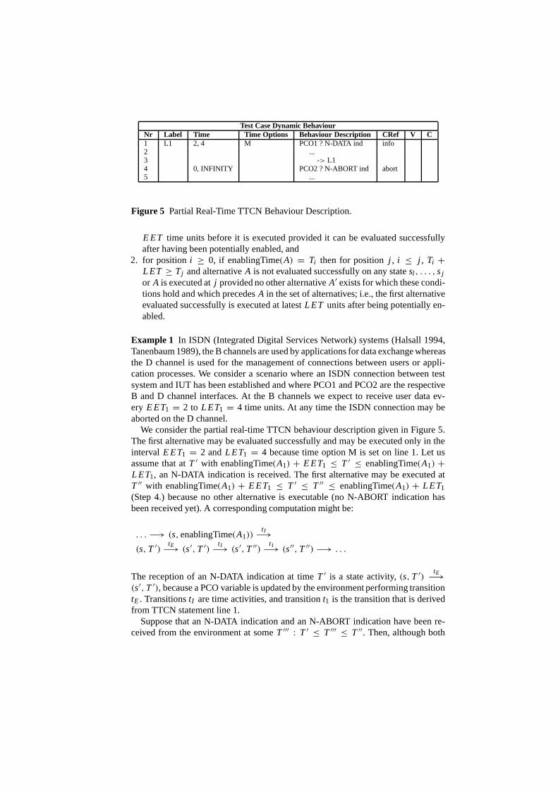
Figure 5 Partial Real-Time TTCN Behaviour Description.
E ET time units before it is executed provided it can be evaluatedsuccessfullyafter having been potentially enabled, and
2. for positioni ≥ 0, if enablingTime(A) = Ti then for positionj , i ≤ j , Ti +
L ET ≥ Tj and alternativeA is not evaluated successfully on any statesl , . . . , sj
or A is executed atj provided no other alternativeA′ exists for which these condi-tions hold and which precedesA in the set of alternatives; i.e., the first alternativeevaluated successfully is executed at latestL ET units after being potentially en-abled.
Example 1 In ISDN (Integrated Digital Services Network) systems (Halsall 1994,Tanenbaum 1989), the B channels are used by applications fordata exchange whereasthe D channel is used for the management of connections between users or appli-cation processes. We consider a scenario where an ISDN connection between testsystem and IUT has been established and where PCO1 and PCO2 are the respectiveB and D channel interfaces. At the B channels we expect to receive user data ev-ery E ET1 = 2 to L ET1 = 4 time units. At any time the ISDN connection may beaborted on the D channel.
We consider the partial real-time TTCN behaviour description given in Figure 5.The first alternative may be evaluated successfully and may be executed only in theinterval E ET1 = 2 andL ET1 = 4 because time option M is set on line 1. Let usassume that atT ′ with enablingTime(A1) + E ET1 ≤ T ′ ≤ enablingTime(A1) +
L ET1, an N-DATA indication is received. The first alternative maybe executed atT ′′ with enablingTime(A1) + E ET1 ≤ T ′ ≤ T ′′ ≤ enablingTime(A1) + L ET1(Step 4.) because no other alternative is executable (no N-ABORT indication hasbeen received yet). A corresponding computation might be:
. . . −→ (s, enablingTime(A1))t I
−→
(s, T ′)tE
−→ (s′, T ′)t I
−→ (s′, T ′′)t1
−→ (s′′, T ′′) −→ . . .
The reception of an N-DATA indication at timeT ′ is a state activity,(s, T ′)tE
−→
(s′, T ′), because a PCO variable is updated by the environment performing transitiontE. TransitionstI are time activities, and transitiont1 is the transition that is derivedfrom TTCN statement line 1.
Suppose that an N-DATA indication and an N-ABORT indicationhave been re-ceived from the environment at someT ′′′ : T ′ ≤ T ′′′ ≤ T ′′. Then, although both

alternatives are executable, the first alternative is executed because of the ordering ofalternatives in the set of alternatives (Step 4.). If an N-DATA indication is received atT < enablingTime(Ai ) + E ET1 then test case execution stops with a FAIL verdict(Step 3.).
If no N-DATA indication and no N-ABORT indication have been received be-fore L ET1 time units after the alternatives have been potentially enabled, test caseexecution stops with a FAIL verdict (Step 2.).
3.4 Discussion of the proposal
If we assume that no time values are defined (in this caseE ET andL ET are zero andinfinity, respectively), execution of a test case results inthe same sequence of state-transitions as in TTCN. Therefore, our definition of real-time TTCN is compatibleto TTCN (ISO9646-3 1996, Baumgarten and Gattung 1996).
Real-time TTCN combines property and requirement orientedspecification styles.Time labels for TTCN statements, in general, define real-time constraints for the testsystem. A test system should be implemented so that it can comply with all prop-erties defined. Time labels for RECEIVE and OTHERWISE events, which imply acommunication with the IUT, define requirements on the IUT and the underlyingservice provider. As well as the test system, the underlyingservice provider is as-sumed to be “sufficiently reliable for control and observation to take place remotely”(ISO9646-1 1994). For real-time TTCN, the underlying service provider should alsobe sufficiently fast with respect to the timing of activities. Therefore, if a timing con-straint of a RECEIVE or OTHERWISE event is violated, this clearly is an indicationthat the IUT is faulty and the test run should end with a FAIL verdict assignment.
In Figure 6, a test case in TTCN is given for the one in Example 1. The timingconstraints on the reception of N-DATA indications are expressed using timers T1and T2. The alternatives coded on lines 2 and 8 in combinationcheck that an N-DATA indication should not be received beforeE ET (= timer T1); otherwise, testcase execution results in a FAIL verdict (line 8). The TIMEOUT event on line 6controls the latest execution time and if timer T2 expires then this gives a FAILverdict.
Let us assume that test case execution is at the third level ofindentation (lines 3, 5and 6) and that TIMEOUT of timer T2 precedes reception of an N-DATA indication.Furthermore, let us assume that the system executing the test case is heavily loadedand therefore evaluation of a set of alternatives lasts too long, so that both eventsare included in the same snapshot. The late arrival of an N-DATA indication getsundetected because of the ordering of alternatives on line 3, 5 and 6. A fast systemwill take a snapshot which includes the TIMEOUT only whereasa slow system willtake a snapshot which includes an N-DATA indication and a TIMEOUT. For theslow system, the RECEIVE succeeds over the TIMEOUT event. Unfortunately, thebehaviour description does not comply with the requirementstated in (ISO9646-

Test Case Dynamic BehaviourNr Label Behaviour Description CRef V C1 L1 START T1(EET)2 ?TIMEOUT T1 START T2(LET-EET)3 PCO1 ? N-DATA indication data4 -> L15 PCO2 ? N-ABORT indication STOP T2 abort INCONC6 ?TIMEOUT T2 FAIL7 PCO2 ? N-ABORT indication STOP T1 abort INCONC8 PCO1 ? OTHERWISE STOP T1 FAIL
Figure 6 TTCN Behaviour Description for Example 1.
1 1994) “that the relative speed of the systems executing thetest case should nothave an impact on the test result” and thus is not valid.
In conclusion, real-time TTCN is more powerful than TTCN. The advantage ofreal-time TTCN is that all requirements on the behaviour of test systems and IUTare made explicit. The timing constraints that are to be met and thus the result of atest case is determined by the observed behaviour only.
4 APPLICATION OF REAL-TIME TTCN
In this section we continue the discussion of real-time TTCNby elaborating on anexample taken from high speed networking.
In ATM (Asynchronous Transfer Mode) networks (Black 1995, Prycker 1995),network traffic control is performed to protect network and users to achieve prede-fined network performance objectives. During connection set up a traffic contractspecificationis negotiated and agreed between users and network. A contract speci-fication consists of the connection traffic descriptor, given in peak cell rate and celldelay variation tolerance; the requested quality-of-service class, given in terms ofrequired cell loss ratio, cell transfer delay and cell delayvariation; and the definitionof a compliant connection.
A connection is termedcompliantas long as the number of non-conforming cellsdoes not exceed a threshold value negotiated and agreed in the traffic contract. If thenumber of non-conforming cells exceeds the threshold then the network may abortthe connection. The procedure that determines conforming and non-conforming cellsis known as thegeneric cell rate algorithm(GCRA(T ,τ )) (Figure 7). The variant wediscuss is referred to asvirtual schedulingand works as follows (Prycker 1995):The algorithm calculates the theoretically predicted arrival times (TAT) of cells as-suming equally spaced cells when the source is active. The spacing between cellsis determined by the minimum interarrival timeT between cells which computes toT = 1/Rp with Rp the peak cell rate (per seconds) negotiated for the connection. Ifthe actual arrival time of a cellta is after TAT− τ , τ the cell delay variation toler-ance caused, for instance, by physical layer overhead, thenthe cell is a conformingcell; otherwise, the cell is arriving too early and thus is being considered as a non-conforming cell. Traffic control subsumes all functions necessary to control, monitor

Arrival of a Cell at time ta
TAT = max(ta, TAT) + TConforming Cell
Non-Conforming Cell ta < TAT - t
No
Yes
At the time of arrival ta of the first cell of the connection, TAT = ta
Next Cell
Figure 7 Generic Cell Rate Algorithm - Virtual Scheduling.
and regulate traffic at the user-network-interface (UNI). The correctly timed deliveryof ATM cells at the UNI is important for a connection to be compliant.
A possible test purpose derivable from the informal definition of traffic contractspecification and GCRA may be as follows: “It is to be tested that the amount oftraffic (in terms of ATM cells) generated at the UNI is compliant to the traffic contractspecification”.
For the following discussion we assume a testing scenario asdepicted in Figure 8.The IUT, i.e., the user’s end-system, is connected to an ATM switch which in thisscenario is the test system. Several ATM sources may generate a continuous streamof ATM cells which is, by the virtual shaper, transformed into a cell stream compliantwith the traffic contract. Via the physical connection of end-system and ATM switchATM cells are transferred. It is the test system that checks compliance of the receivedcell stream to the traffic contract.
The definition of a test case assumes that a connection has already been estab-lished so that a traffic contract specification is available.From the traffic contract,parametersRp, T andτ can be extracted which are assigned to test case variables.The threshold value (for determining when a connection is tobe aborted) is providedas a test suite parameter. For simplicity we letτ = 0.
The definition of the dynamic test case behaviour (Figure 9) is based on the obser-vation that according to the GCRA, except for the first cell, at most everyT(= E ET)
time units an ATM cell is expected from the IUT. Since we do notexpect an ATMcell to arrive beforeT time units, time option M is defined. If an ATM cell arrivesbeforeT time units then the test case is terminated with a FAIL verdict.
This test case implies a threshold value of zero. If we allow for a number of non-conforming cells (NCC) greater than zero then the test case definition changes asshown in Figure 10. The difference compared to the previously discussed test caseis that whenever an ATM cell arrives beforeT time units then counter NCC is in-cremented and is checked against the defined threshold. Timeoption N on line 2instructs the system not to pre-empt the time constraint of the current set of alterna-tives. If control returns to level L2 from line 5 the enablingtime is not updated.

MUX Virtual ShaperATM Switchperforming
controltraffic
ATM Layer
Phy Laser SAPT
raffi
c S
ourc
es
Physical Layer
Implementation Under Test
CDV tolerance
UNI
Test System
Figure 8 Generic Cell Rate Algorithm - Testing Scenario.
Test Case Dynamic BehaviourNr Label Time Time Behaviour CRef V C
Options Description1 0, INFINITY UNI ? ATM-Cell ? First cell to
initialize GCRA2 L2 T, INFINITY M UNI ? ATM-Cell ?3 -> L2
Figure 9 Real-Time TTCN Behaviour Description for GCRA - Threshold= 0.
We have shown the use of time labels and time options. Withouttime options (in aprevious paper, (Walteret al. 1997), we have used time labels only) the specificationof both test cases would have been more complex. For the first test case it would havebeen necessary to introduce a second alternative similar toline 2 of Figure 10 insteadof using time option M. For the second test case without time option N calculationsof absolute and relative time values would have be necessaryin order to adjustE ET.Nonetheless, without real-time features, testing GCRA would have been impossible.
Test Case Dynamic BehaviourNr Label Time Time Behaviour CRef V C
Options Description1 0, INFINITY UNI ? ATM-Cell (NCC := 0) ?2 L2 0, T N UNI ? ATM-Cell ?
(NCC := NCC + 1)3 [NCC > Threshold] FAIL4 [NCC <= Threshold]5 -> L26 T, INFINITY UNI ? ATM-Cell ?7 -> L2
Figure 10 Real-Time TTCN Behaviour Description for GCRA - Threshold> 0.
5 CONCLUSIONS AND OUTLOOK
We have defined syntax and semantics of real-time TTCN. On a syntactical levelTTCN statements can be annotated by time labels. Time labelsare interpreted as ear-liest and latest execution times of TTCN statements relative to the enabling time ofthe TTCN statement. The operational semantics of real-timeTTCN is based on timedtransition systems (Henzingeret al. 1991). We have described the interpretation ofreal-time TTCN in timed transition systems. The applicability of real-time TTCNhas been shown by an example: We have defined test cases for thegeneric cell ratealgorithm employed in ATM networks for traffic control (Black 1995, Prycker 1995).
The motivation for our work has been given by the demand for a test languagethat can express real-time constraints. The increasing distribution of multimedia ap-plications and real-time systems impose requirements on the expressive power of atest language that are not met by TTCN. Particularly, real-time constraints can notbe expressed. However, for the mentioned new applications correctness of an imple-mentation also with respect to real-time behaviour is essential and, thus, should alsobe tested.
In our approach a TTCN statement is annotated by time labels.The advantagesof this approach are twofold: Firstly, only a few syntactical changes are necessary.Secondly, TTCN and real-time TTCN are compatible: If we assume that zero andinfinity are earliest and latest execution times, a computation of a real-time TTCNtest case is the same as in TTCN. A possible extension of our approach is to allowthe use of time labels at a more detailed level, e.g., the annotation of test events,assignments and timer operations (an extension of (Walteret al. 1992, Walter andPlattner 1992)). Our future work will focus on these aspects.
Acknowledgements. The authors are indebted to Stefan Heymer for proofreadingand for his detailed comments on earlier drafts of this paper. We are also gratefulto the anonymous reviewers providing detailed comments andvaluable suggestionswhich have improved contents and presentation of this paper.
6 REFERENCES
R. Alur, T. Feder, T. Henzinger.The Benefits of Relaxing Punctuality. Journal of theACM, Vol. 43, 1996.
A. Ates, B. Sarikaya.Test sequence generation and timed testing. In Computer Net-works and ISDN Systems, Vol. 29, 1996.
B. Baumgarten, A. Giessler.OSI conformance testing methodology and TTCN. El-sevier, 1994.
B. Baumgarten, G. Gattung.A Proposal for the Operational Semantics of ConcurrentTTCN. Arbeitspapiere der GMD 975, 1996.
H. Bowman, L. Blair, G. Blair, A. Chetwynd.A Formal Description Technique Sup-porting Expression of Quality of Service and Media Synchronization. In Mul-timedia Transport and Teleservices. LNCS 882, 1994.

B. Berthomieu, M. Diaz.Modeling and Verification of Time Dependent Systems Us-ing Time Petri Nets. In IEEE Transactions on Software Engineering, Vol. 17,No. 3, March 1991.
U. Black.ATM - foundation for broadband networks. Prentice-Hall, 1995.A. Danthine, Y. Baguette, G. Leduc, Léonard.The OSI 95 Connection-Mode Trans-
port Service - The Enhanced QoS. In High Performance Networking, IFIP,1992.
S. Fischer.Implementation of multimedia systems based on a real-time extension ofEstelle. In Formal Description Techniques IX Theory, application and tools,1996.
F. Halsall,Data Communications, Computer Networks and Open Systems, Addison-Wesley, 1994.
D. Hogrefe, S. Leue.Specifying Real-Time Requirements for Communication Proto-cols. Technical Report IAM 92-015, University of Berne, 1992.
T. Henzinger, Z. Manna, A. Pnueli.Timed Transition Systems. In Real-Time: Theoryin Practice. LNCS 600, 1991.
ISO/IEC. Information Technology - OSI - Conformance Testing Methodology andFramework - Part 1: General Concepts. ISO/IEC IS 9646-1, 1994.
ISO/IEC. Information Technology - OSI - Conformance Testing Methodology andFramework - Part 2: Abstract Test Suite Specification. ISO/IEC IS 9646-2,1994.
ISO/IEC. Information Technology - OSI - Conformance Testing Methodology andFramework - Part 3: The Tree and Tabular Combined Notation (TTCN).ISO/IEC IS 9646-3, 1996.
R. Keller.Formal Verification of Parallel Programs. In Communications of the ACM,Vol. 19, No. 7, 1976.
F. Kristoffersen, T. Walter.TTCN: Towards a formal semantics and validation of testsuites. In Computer Network and ISDN Systems, Vol. 29, 1996.
L. Léonard, G. Leduc.An Enhanced Version of Timed LOTOS and its Application toa Case Study. In Formal Description Techniques VI, North-Holland, 1994.
S. Leue.Specifying Real-Time Requirements for SDL Specifications -A TemporalLogic Based Approach. In Protocol Specification, Testing and VerificationXV, 1995.
R. Linn.Conformance Evaluation Methodology and Protocol Testing. In IEEE Jour-nal on Selected Areas in Communications, Vol. 7, No. 7, 1989.
P. Merlin, D. Faber.Recoverability of Communication Protocols. In IEEE Transac-tions on Communication, Vol. 24, No. 9, September 1976.
M. Prycker.Asynchronous transfer mode: solutions for broadband ISDN, 3rd Edi-tion, Prentice Hall, 1995.
R. Probert, O. Monkewich.TTCN: The International Notation for Specifying Tests ofCommunications Systems. In Computer Networks and ISDN Systems, Vol.23, 1992.
J. Quemada, A. Fernandez.Introduction of Quantitative Relative Time into LOTOS.In Protocol Specification, Testing and Verification VII, North-Holland, 1987.

B. Sarikaya.Conformance Testing: Architectures and Test Sequences. In ComputerNetworks and ISDN Systems, Vol. 17, 1989.
I. Sommerville.Software engineering. 3rd Edition, Addison-Wesley, 1989.A. Tanenbaum,Computer Networks, Prentice-Hall, 1989.T. Walter, J. Ellsberger, F. Kristoffersen, P.v.d. Merkhof. A Common Semantics Rep-
resentation for SDL and TTCN. In Protocol Specification, Testing and Veri-fication XII, North-Holland, 1992.
T. Walter, B. Plattner.An Operational Semantics for Concurrent TTCN. In Proceed-ings Protocol Test Systems V, North-Holland, 1992.
T. Walter, J. Grabowski.A Proposal for a Real-Time Extension for TTCN. In Kom-munikation in Verteilten Systemen ’97, Informatik aktuell, Springer Verlag,1997.
7 BIOGRAPHY
Thomas Walter received his Diploma in Informatics and his Doctorate degree inelectrical engineering in 1987 and 1993, respectively. Since 1986 he is with the Com-puter Engineering and Networks Laboratory (TIK) of the Swiss Federal Institute ofTechnology (ETHZ). In the years 1991 and 1992 he led a projectat the ETSI and in1994 he participated in an EWOS project; both projects were in conformance testing.His current research interests include formal methos for specification and validationof real-time systems. Besides this he is also active in setting up an infrastructure forteleteaching at ETHZ.
Jens Grabowski studied Computer Science at the University of Hamburg, Germany,where he graduated with a diploma degree in 1990. From 1990 to1995 he was re-search scientist at the University of Berne, Switzerland, where he received his Ph.D.degree in 1994. Since October 1995 Jens Grabowski is researcher and lecturer at theInstitute for Telematics at the University of Lübeck, Germany. His research activitiesare directed towards network analysis, formal methods in protocol specification andconformance testing.