real-time simulation of more-electric aircraft power systems · toward aircraft electric system...
TRANSCRIPT
Paper presented at the EPE'13 ECCE Europe conference, September 3-5, 2013, Lille, France
Real-time Simulation of More-Electric Aircraft Power Systems
Leonardo Montealegre Lobo Instituto Costarricense de Electricidad
Department of Research and Development Apdo. 10032-1000, San Jose, Costa Rica
Christian Dufour Opal-RT Technologies
1751 Richardson, suite 2525 Montreal, PQ, H3K 1G6, Canada
Jean Mahseredjian École Polytechnique de Montréal
Department of Electrical Engineering Montreal, PQ, H3T 1J4, Canada [email protected]
Acknowledgements
This paper has been realized in the framework of projects supported and funded by Bombardier Aerospace, OPAL-RT Technologies, Pratt & Whitney Canada and by the Consortium for Research and Innovation in Aerospace in Quebec (CRIAQ).
Keywords
More-Electric-Aircraft, Power Management, Real time simulation, Test bench, certification.
Abstract
The More-Electric Aircraft (MEA) requires thorough testing procedures to meet extreme security requirements. Real-time simulation technologies have been traditionally part of this validation and testing process for conventional aircraft designs. The MEA concept is now pushing HIL technologies toward aircraft electric system real-time simulation. This paper discusses the real-time simulation requirements for MEA, analyses an aircraft electrical power system, identifies real-time modeling bottlenecks and validation needs. The case of Bombardier Global Express aircraft is used for this purpose.
Introduction
Traditional aircrafts use pneumatic, hydraulic, mechanical and electrical energy sources to supply their systems, which normally imply increases in fuel consumption, low power efficiency and heavier aircraft weight. Therefore, a new concept in aircraft industry (the more-electric concept) has tried to considerably reduce the impact of these trends, by increasing the implementation of electrical components in aircrafts for generating, distributing and utilizing electrical power. Thus, the more-electric aircraft (MEA) concept impacts significantly on aircraft electrical power system design, due to the fact that many functions conventionally managed by hydraulic, pneumatic and mechanical power are replaced by electric systems in order to reduce size and weight, and improve fuel efficiency [1]. In contrast, the increased usage of electrical power intensifies the power demands on the electrical system, placing new constraints on its dynamic performances and on power quality, so that new power system architectures must be designed, extensively analyzed, tested, validated and certified before implementation in an actual aircraft. In this context, mathematical modeling and simulation tools constitute an efficient approach for predicting operational behavior, correcting design errors, eliminating prototyping steps and reducing component and overall testing cycles. This is essential to study the impact on costs and electric design modifications. Furthermore, efforts have been made to develop studies on power distribution systems
Paper presented at the EPE'13 ECCE Europe conference, September 3-5, 2013, Lille, France
at fixed frequency [2] [3], variable frequency [4], and power distribution at high DC voltage [5]. Regardless of the existence of all these studies, many approximations are made, either by necessity or by lack of data. Consequently, research must be pursued in order to study the stability of new distribution architectures with more precision, as the presence of power electronics on aircrafts is in constant growth [6]. This is part of the model-based design paradigm in used for many years in the aerospace industry [7]. Real-time simulation tools are a robust and practical way to face these challenges during MEA’s concept implementation. In addition, real-time simulation tools offer the computational speed advantage and allow studying a very large number of operational scenarios in less time. Moreover, such tools can provide real-time synchronized simulations and allow interfacing with external physical devices (hardware-in-the-loop), which can be used to validate physical controllers, improve designs and even develop models. This paper presents an initial benchmark for the real-time simulation and analysis of the Bombardier Global Express (GLEX) aircraft electrical power system. The tools considered are Simulink [8] (for an off-line first implementation model) and the OPAL-RT [9] simulator for real-time simulations. In addition, some validations on the off-line model are performed using EMTP-RV [10]. It is shown that these tools allow the development of advanced models and testing the aircraft system in a wide range of scenarios. The real-time simulation of the developed power system is particularly complex. Consequently, a new real-time simulation method called SSN [11] (State-Space Nodal method) is used and tested successfully for this class of simulation problem.
Testing Standards
In the frame of many research programs around North America and Europe, one of the main drivers for MEA’s design, integration and performance has been the testing standards. The aim of these standards is to further understand the requirements and explore the challenges for characterizing new aircraft electric systems in terms of total power and power quality. For the scope of this paper, the military standard MIL-STD704F [12] is used to assess power quality in terms of DC bus voltage deviation under both normal and transient behavior. MIL-STD704F establishes the requirements and characteristics of aircraft electric power provided at the input terminals of electric utilization equipment [12]. Moreover, MIL-STAD704F provides a range of acceptable voltage values under both steady-state and transient behavior. In addition, the military standard MIL-E-7016 [13] is used to perform an electrical load analysis on the GLEX’s load buses. This standard addresses the methods and analysis of electric loads and source capacity on military aircraft [13]. Although both standards were prepared specifically for military assignments, their use for commercial applications has received a widespread acceptance over the years. Furthermore, other avionics test standards, for both military and commercial purposes, are performed along with [12] and [13]. For instance, system behavior must comply with Airbus directives such as ABD01.1.8 [14]. In other cases, the increasing number of power electronic loads would comprise a high number of AC-DC rectifier stages, which would have to comply with the Airbus’ AC quality standard (ABD100.1.8.1) [15].
Paper presented at the EPE'13 ECCE Europe conference, September 3-5, 2013, Lille, France
Modeling of GLEX Aircraft Electrical Power System
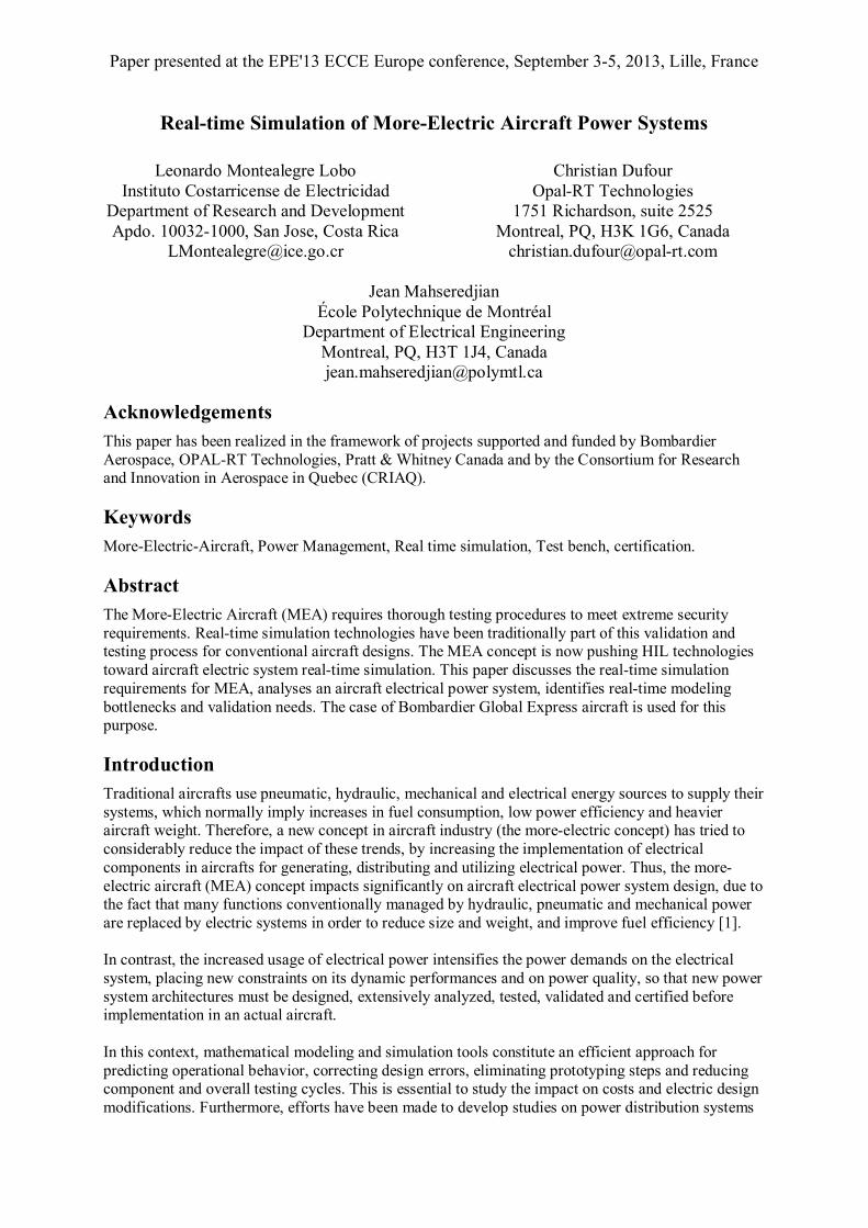
The GLEX electric system is separated into AC and DC systems, as shown in Fig. 1. The AC system uses variable frequency generators (VFG) to supply 115/200 VAC, variable frequency (324-596 Hz) 3-phase AC power. For the purpose of this paper, the VFGs are modeled using ideal voltage sources. However, this will be upgraded to include electromechanical dynamics and contributions to electromagnetic transients. The generator outputs are supplied to the AC Power Centre (ACPC), which in turn distributes the power to the aircraft subsystems. The ACPC is a sort of switching control center for automatic AC supply reconfiguration in case of failure and it is based on truth tables representing GLEX reconfiguration logic [16]. It is responsible for sending binary signals to the external switching time control for the ACPC switches, in order to change ON/OFF state positions. The amount of logical controls is vast and implementing all of them is not the goal of this paper. Only basic architecture reconfiguration according to VFG’s and TRU’s status is executed in the GLEX electric system.
Fig. 1: One-line diagram of aircraft electric power system Within the AC systems, AC cable impedance parameters are created, scripted in Simulink and then validated in EMTP-RV. Zero, positive and negative sequence impedances are given according to [17]. A correction factor is applied to use the inductive reactance given in [17] for the entire range of operations frequencies. A sequence impedance matrix is formed for each wire size from 12 AWG to 00 AWG. Phase domain cable impedance parameters are found using the Clarke transformation matrix and finally a coupled-RL model (depending on frequency operation, length and wire size) is fully implemented in GLEX’s Simulink model. Moreover, both passive and dynamic AC loads are considered in the model.
Paper presented at the EPE'13 ECCE Europe conference, September 3-5, 2013, Lille, France
The DC power system supply consists of four Transformer Rectifier Units (TRUs) for normal power distribution and two NiCad batteries (nickel-cadmium). Each TRU produces unregulated 28 VDC, rated at 150 A [16]. Lack of information prevents modeling the TRU as in [18] so that a simplified model similar to [18] is created in Simulink, using a 12-pulse power converter. For DC cable modeling, a block is created, edited and scripted in Simulink to generate DC cable impedance based on [17]. However, more sophisticated models could be developed to account for higher frequency transients. For instance, it might be needed to account for temperature and altitude effects using dynamic functions. In addition, DC loads are assumed to be constant impedance loads, drawing a specific current at 28 VDC, while NiCad batteries are modeled using simple ideal DC sources.
Real-time Modeling of GLEX Aircraft Electric Power System
In order to use a Simulink model in real-time with OPAL-RT’s software and hardware, some modeling concepts must be followed when building the application. One of the most important concepts in real-time simulation using OPAL-RT is grouping the model into parallel subsystems (each subsystem is assigned to a single CPU), using various parallelizations, so that the real-time model can be computed on multiple cores for achieving real-time performance. In addition, Fig. 1 presents the GLEX electric system grouped into parallel subsystems or RT-LAB cores. One of the main challenges of MEA real-time simulation resides in the very large number of switches in the circuits that are closely coupled to each other due to the lumped nature of MEA circuits. The ARTEMiS-SSN solver provides a very good solution to this challenge.
Real-time Modeling Using the ARTEMiS SSN Solver
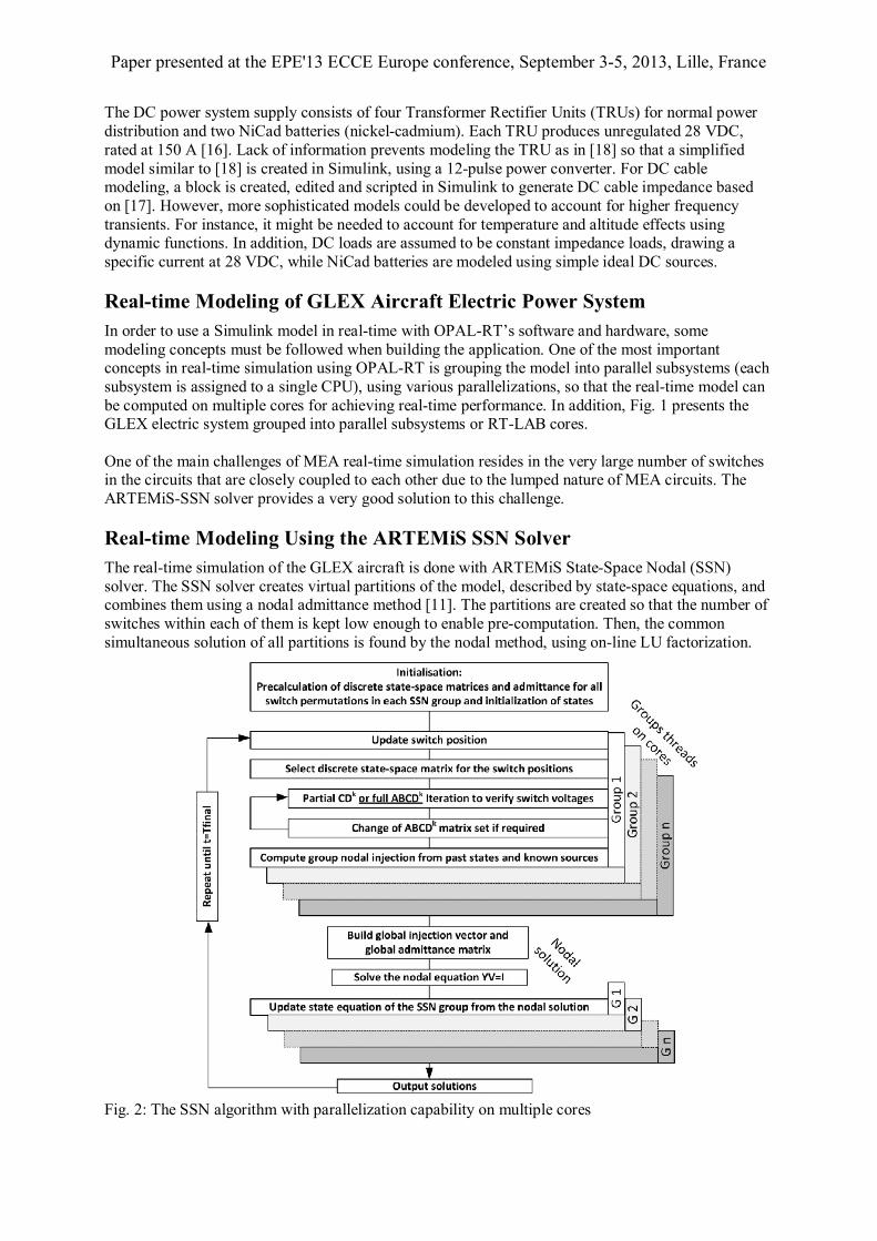
The real-time simulation of the GLEX aircraft is done with ARTEMiS State-Space Nodal (SSN) solver. The SSN solver creates virtual partitions of the model, described by state-space equations, and combines them using a nodal admittance method [11]. The partitions are created so that the number of switches within each of them is kept low enough to enable pre-computation. Then, the common simultaneous solution of all partitions is found by the nodal method, using on-line LU factorization.
Fig. 2: The SSN algorithm with parallelization capability on multiple cores
Paper presented at the EPE'13 ECCE Europe conference, September 3-5, 2013, Lille, France
This allows for the simulation of large circuits without any added artificial delays and with a large number of switches, provided that these switches are grouped in different partitions (or ‘SSN groups’). One particularity of the SNN algorithm and its implementation into the OPAL-RT simulator is that SSN partitions can be computed in parallel in different cores of the simulator to further accelerate the simulation. The SSN algorithm is depicted in Fig. 2. As mentioned before, one of the main challenges in the real-time simulation of the electric circuit of an aircraft is the very high number of topologically connected switches or breakers. In the case of the GLEX model, there are a total of 109 switches. These switches are grouped into 25 SSN partitions combined with a nodal admittance matrix of rank 48, which is 80% sparse. The model, grouped into 25 SSN partitions, is executed in real-time on the RT-LAB platform (v.10.6) at a time step of 39 µs. The RT-LAB target was a 3.33GHz 12-core PC running under RT-Linux. To achieve this performance, the SSN simulation used 4 cores in parallel and made tri-diagonal reordering of the nodes to take advantage of the sparsity of the nodal matrix, by using a non-sparse method. Further gain in performance is expected when a fully sparse method will be available in SSN [20]. Some tests, involving steady-state and transient behavior, are performed on the GLEX’s electric system model in order to validate real-time performance. Description of the tests and results are shown in the next section.
Test Results for the Global Express Aircraft
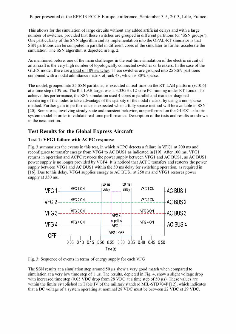
Test 1: VFG1 failure with ACPC response
Fig. 3 summarizes the events in this test, in which ACPC detects a failure in VFG1 at 200 ms and reconfigures to transfer energy from VFG4 to AC BUS1 as indicated in [19]. After 100 ms, VFG1 returns in operation and ACPC restores the power supply between VFG1 and AC BUS1, as AC BUS1 power supply is no longer provided by VGF4. It is noticed that ACPC transfers and restores the power supply between VFG1 and AC BUS1 within the 50 ms delay for switching operation, as required in [16]. Due to this delay, VFG4 supplies energy to AC BUS1 at 250 ms and VFG1 restores power supply at 350 ms.
Fig. 3: Sequence of events in terms of energy supply for each VFG The SSN results at a simulation step around 50 µs show a very good match when compared to simulation at a very low time step of 1 µs. The results, depicted in Fig. 4, show a slight voltage drop with increased time step (0.05 VDC drop from 28 VDC at a time step of 50 µs). These values are within the limits established in Table IV of the military standard MIL-STD704F [12], which indicates that a DC voltage of a system operating at nominal 28 VDC must be between 22 VDC et 29 VDC.

Paper presented at the EPE'13 ECCE Europe conference, September 3-5, 2013, Lille, France
Fig. 4: DC ESS Bus for real-time and off-line simulations In addition, Fig. 5 shows current simulation results for all VFG buses when VFG1 fails at 200 ms and restores operation at 350 ms. It is observed that VFG4 supplies more current when VFG1 is off. The magnitude and duration of the overcurrent in VFG4, as well as the magnitude of currents at new steady-state operation, meet the requirements established in [12]. Furthermore, steady-state voltages of all VFG buses before the failure and after the recovery are within the established in Table II of the military standard MIL-STD704F [12], which indicates that an AC voltage of a variable frequency system operating at nominal 115 VAC must be between 108 VAC and 118 VAC. Finally, transient behavior of all VFG buses behaves according to the Envelope of Normal AC Voltage Transient, as in Figure 3 of the military standard MIL-STD704F [12].
Fig. 5: Zoom in the current simulation results from VFG buses when VFG1 fails
0.1 0.15 0.2 0.25 0.3 0.35 0.4 0.45 0.514
16
18
20
22
24
26
28
30
Time (s)
Vol
tage
(VD
C)
SPS 1us
SPS 50us
SSN 50us
0.2 0.22 0.24 0.26 0.28 0.3 0.32 0.34 0.36
-50
0
50
VFG1 Bus
Cur
rent
(A
AC)
0.25 0.255 0.26 0.265 0.27 0.275 0.28 0.285 0.29 0.295 0.3
-100
0
100
Cur
rent
(AA
C)
VFG2 Bus
0.25 0.255 0.26 0.265 0.27 0.275 0.28 0.285 0.29 0.295 0.3
-100
0
100
Cu
rre
nt
(AA
C)
VFG3 Bus
0.25 0.26 0.27 0.28 0.29 0.3
-100
0
100
VFG4 Bus
Time (s)
Cu
rre
nt
(AA
C)
Phase A
Phase B
Phase C
Paper presented at the EPE'13 ECCE Europe conference, September 3-5, 2013, Lille, France
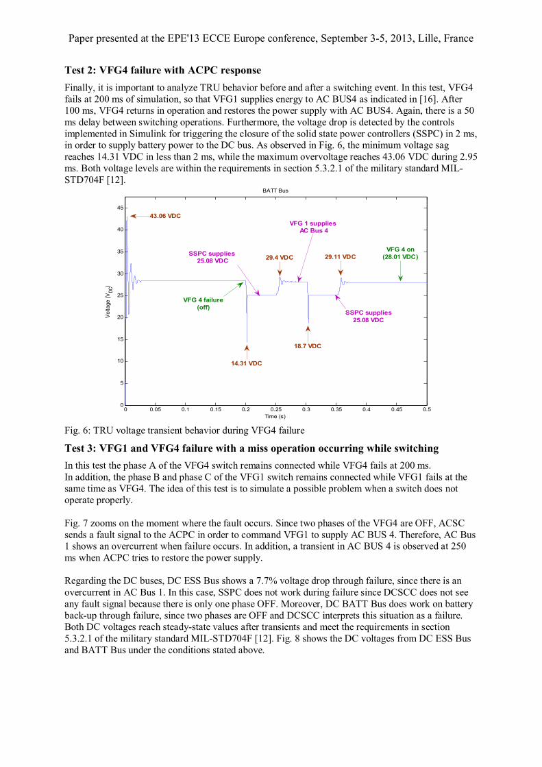
Test 2: VFG4 failure with ACPC response
Finally, it is important to analyze TRU behavior before and after a switching event. In this test, VFG4 fails at 200 ms of simulation, so that VFG1 supplies energy to AC BUS4 as indicated in [16]. After 100 ms, VFG4 returns in operation and restores the power supply with AC BUS4. Again, there is a 50 ms delay between switching operations. Furthermore, the voltage drop is detected by the controls implemented in Simulink for triggering the closure of the solid state power controllers (SSPC) in 2 ms, in order to supply battery power to the DC bus. As observed in Fig. 6, the minimum voltage sag reaches 14.31 VDC in less than 2 ms, while the maximum overvoltage reaches 43.06 VDC during 2.95 ms. Both voltage levels are within the requirements in section 5.3.2.1 of the military standard MIL-STD704F [12].
Fig. 6: TRU voltage transient behavior during VFG4 failure
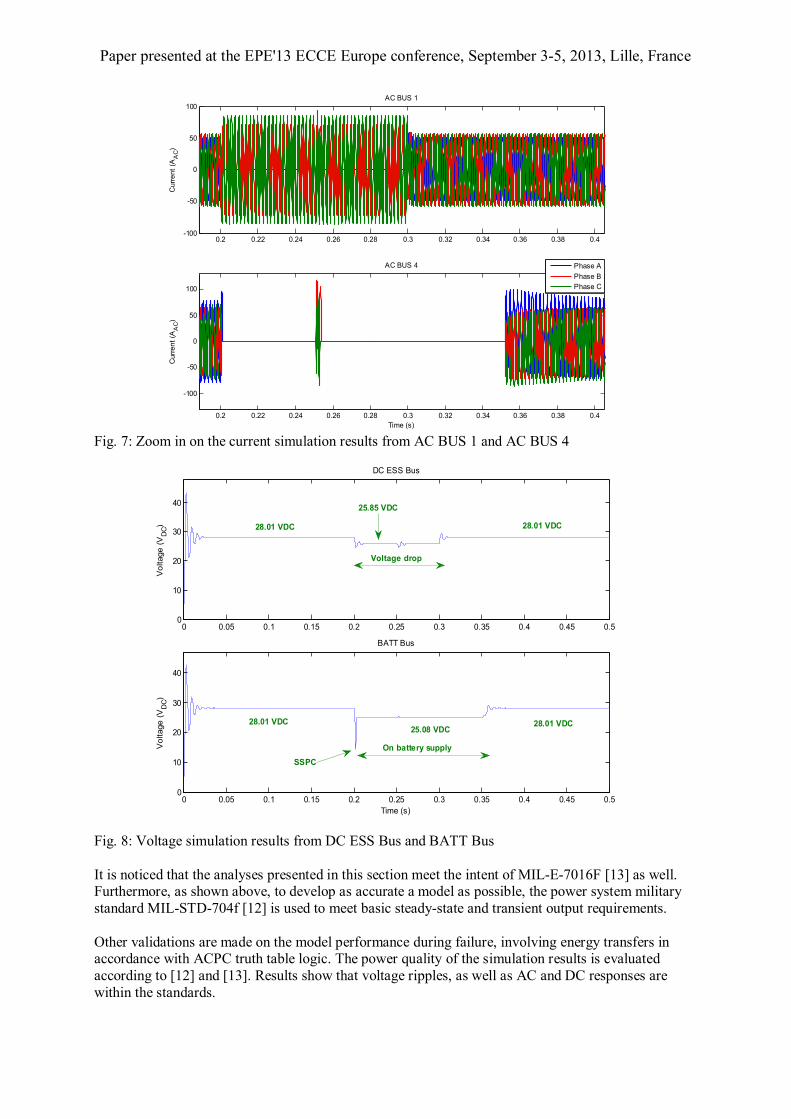
Test 3: VFG1 and VFG4 failure with a miss operation occurring while switching
In this test the phase A of the VFG4 switch remains connected while VFG4 fails at 200 ms. In addition, the phase B and phase C of the VFG1 switch remains connected while VFG1 fails at the same time as VFG4. The idea of this test is to simulate a possible problem when a switch does not operate properly. Fig. 7 zooms on the moment where the fault occurs. Since two phases of the VFG4 are OFF, ACSC sends a fault signal to the ACPC in order to command VFG1 to supply AC BUS 4. Therefore, AC Bus 1 shows an overcurrent when failure occurs. In addition, a transient in AC BUS 4 is observed at 250 ms when ACPC tries to restore the power supply. Regarding the DC buses, DC ESS Bus shows a 7.7% voltage drop through failure, since there is an overcurrent in AC Bus 1. In this case, SSPC does not work during failure since DCSCC does not see any fault signal because there is only one phase OFF. Moreover, DC BATT Bus does work on battery back-up through failure, since two phases are OFF and DCSCC interprets this situation as a failure. Both DC voltages reach steady-state values after transients and meet the requirements in section 5.3.2.1 of the military standard MIL-STD704F [12]. Fig. 8 shows the DC voltages from DC ESS Bus and BATT Bus under the conditions stated above.
0 0.05 0.1 0.15 0.2 0.25 0.3 0.35 0.4 0.45 0.50
5
10
15
20
25
30
35
40
45
Time (s)
Vo
ltage
(V
DC)
BATT Bus
VFG 1 supplies AC Bus 4
14.31 VDC
43.06 VDC
29.4 VDC
18.7 VDC
29.11 VDCVFG 4 on
(28.01 VDC)
SSPC supplies25.08 VDC
SSPC supplies 25.08 VDC
VFG 4 failure(off)
Paper presented at the EPE'13 ECCE Europe conference, September 3-5, 2013, Lille, France
Fig. 7: Zoom in on the current simulation results from AC BUS 1 and AC BUS 4
Fig. 8: Voltage simulation results from DC ESS Bus and BATT Bus It is noticed that the analyses presented in this section meet the intent of MIL-E-7016F [13] as well. Furthermore, as shown above, to develop as accurate a model as possible, the power system military standard MIL-STD-704f [12] is used to meet basic steady-state and transient output requirements. Other validations are made on the model performance during failure, involving energy transfers in accordance with ACPC truth table logic. The power quality of the simulation results is evaluated according to [12] and [13]. Results show that voltage ripples, as well as AC and DC responses are within the standards.
0.2 0.22 0.24 0.26 0.28 0.3 0.32 0.34 0.36 0.38 0.4-100
-50
0
50
100
Curr
en
t (A
AC)
AC BUS 1
0.2 0.22 0.24 0.26 0.28 0.3 0.32 0.34 0.36 0.38 0.4
-100
-50
0
50
100
Time (s)
Curr
en
t (A
AC
)
AC BUS 4
Phase A
Phase B
Phase C
0 0.05 0.1 0.15 0.2 0.25 0.3 0.35 0.4 0.45 0.50
10
20
30
40
Vo
ltage
(V
DC)
DC ESS Bus
0 0.05 0.1 0.15 0.2 0.25 0.3 0.35 0.4 0.45 0.50
10
20
30
40
Time (s)
Vo
ltage
(V
DC)
BATT Bus
28.01 VDC
28.01 VDC
SSPC
On battery supply
25.08 VDC28.01 VDC
Voltage drop
25.85 VDC
28.01 VDC
Paper presented at the EPE'13 ECCE Europe conference, September 3-5, 2013, Lille, France
Conclusion
This paper presented an initial attempt to model GLEX electric systems in steady state and transient behaviors for real-time simulation. It demonstrated the capability to study system performance under given operating conditions and potential benefits of conducting real-time simulations for MEA electric systems. This testing methodology can be used to study various aircraft power system architectures and test their performance within practical economical and reliability constraints. The paper also demonstrated that the SSN solver is efficient enough to enable real-time simulation of MEA with a very high number of switches present in the model. Further work is ongoing with the objective of decreasing the time step of the real-time simulations, increasing the number of switches usable in real-time simulation and performing faster HIL tests, as required by complex MEA’s electric systems. New concepts or designs are constantly emerging and must be extensively analyzed, tested, validated and certified before its implementation in an actual aircraft. One long term objective of this work is to contribute to the creation of a model-based certification process for MEA, for research on simulation methods for aircraft power systems.
References
[1] R. Newman, "The more electric engine concept," Society of Automotive Engineers, 2004.
[2] A. Eid, H. El-Kishky, M. Abdel-Salam, and M.T. El-Mohandes, "On Power Quality of Variable-Speed Constant-Frequency Aircraft Electric Power Systems," IEEE Transactions on Power Delivery, vol. 25, no. 1, pp. 55-65, January 2010.
[3] A. Eid, H. El-Kishky, M. Abdel-Salam, and T. El-Mohandes, "Power quality investigations of VSCF aircraft electric power systems," in 2010 42nd Southeastern Symposium on System Theory (SSST), Tyler, TX, USA, 2010, pp. 171-176.
[4] T. Jomier, "Final public MOET Technical Report," European Commission 6th Framework Programme, Toulouse, France, Technical Report D0.02.3, 2009.
[5] NASA. (2010, November) Dryden Flight Research Center. [Online]. http://www.nasa.gov/centers/dryden/home/index.html
[6] M.A. Lemaire, L. Montealegre Lobo, J. Mahseredjian, F. Sirois, and C. Lavoie, "Simulation of aircraft electrical power systems: tools and challenges," in Canadian Aeronautics and Space Institute AERO 2011, Montreal, Canada, 2011.
[7] S. Cavalcanti, and M. Papini, "Preliminary Model Matching of the EMBRAER 170 Jet," Journal of Aircraft, vol. 41, no. 4, pp. 703-710, 2004.
[8] Simulink, "User's Guide," The Math Works Inc., Version 7.4 November 2012. [Online]. http://www.mathworks.com/products/simulink/
[9] C. Dufour, L-A. Grégoire, and J. Bélanger, "Solvers for Real-Time Simulation of Bipolar Thyristor-Based HVDC and 180-cell HVDC Modular Multilevel Converter for System Inteconnection and Distributed Energy Integration," in 2011 CIGRE Conference Proceedings, Recife, Brazil, April, 2011.
[10] Jean Mahseredjian, S. Dennetière, L. Dubé, B. Khodabakhchian, and L. Gérin-Lajoie, "On a new approach for the simulation of transients in power systems," Electric Power Systems Research, vol. 77, no. 11, pp. 1514-1520, September 2007.
[11] C. Dufour, J. Mahseredjian, and J. Belanger, "A Combined State-Space Nodal Method for the Simulation of Power System Transients," IEEE Transactions on Power Delivery, vol. 26, no. 2, pp. 928-935, April 2011.
[12] Department of Defense, "Aircraft Electric Power Characteristics," United State Department of Defense, Washington, USA, Military Standard MIL-STD-704f, 2004.
[13] Department of Defense, "Analysis of Electric Load and Power Source Capacity," United State Department of Defense, Washington, USA, Military Standard MIL-E-7016, 1976.
[14] J. Faucher, Aeroconseil Aircraft Eng, “Simulation Study of new Aircraft Electrical Power Network performances”, MOET Forum, Barcelona, Sept 2009, http://www.eurtd.com/moet/PDF/B.pdf

Paper presented at the EPE'13 ECCE Europe conference, September 3-5, 2013, Lille, France
[15] J.C. Swierczek, F. Moller, C. Saudemont, R. Meuret, and B. Robyns, "Power Management of a Regenerative Local HVDC Aircraft Network Using Supercapacitors," in Proceedings of the 15th International Power Electronics and Motion Control Conference, EPE-PEMC 2012 ECCE Europe, Novi Sad, Serbia, 2012, pp. LS4a.5
[16] Bombardier Aerospace, "ATA 24, Technical Training Guide," Montreal, Canada, Technical Report 2003.
[17] S.J. Exner, "Impedance Data for 400-Cycle Aircraft Distribution Systems" AIEE, Technical Paper 1952.
[18] K.W.E. Cheng, "Comparative study of AC/DC converters for more electric aircraft," in Proceedings of the 1998 7th International Conference on Power Electronics and Variable Speed Drives, London, UK, 1998, pp. 229-304.
[19] F. Tinney and W.S. Meyer, "Solution of Large Sparse Systems by Ordered Triangular Factorization," IEEE Transactions on Automatic Control, vol. 18, no. 4, pp. 333 - 346, August 1973.