real-time particulate filter soot and ash measurements ... · measurements, optimized control, and...
TRANSCRIPT
1
Real-Time Particulate Filter Soot and Ash
Measurements, Optimized Control, and
Diagnostics via Radio Frequency Sensing
Alexander Sappok, Paul Ragaller, Leslie Bromberg
www.dpfsensor.com
CLEERS Workshop
April 28, 2015
2
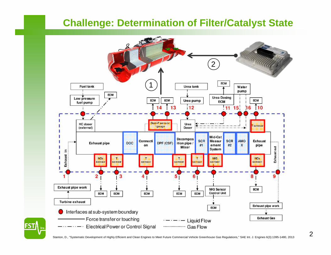
Challenge: Determination of Filter/Catalyst State
Stanton, D., "Systematic Development of Highly Efficient and Clean Engines to Meet Future Commercial Vehicle Greenhouse Gas Regulations," SAE Int. J. Engines 6(3):1395-1480, 2013
1
2
3
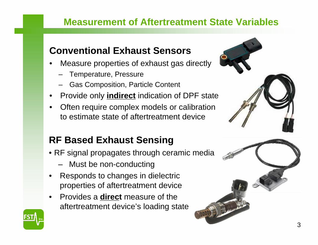
Conventional Exhaust Sensors• Measure properties of exhaust gas directly
– Temperature, Pressure– Gas Composition, Particle Content
• Provide only indirect indication of DPF state• Often require complex models or calibration
to estimate state of aftertreatment device
RF Based Exhaust Sensing• RF signal propagates through ceramic media
– Must be non-conducting• Responds to changes in dielectric
properties of aftertreatment device• Provides a direct measure of the
aftertreatment device’s loading state
Measurement of Aftertreatment State Variables
4
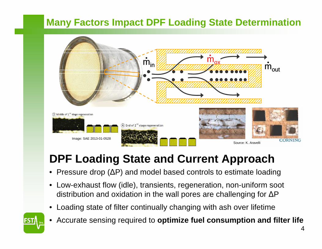
minminmoxmox moutmout
Soot and Ash Plugging
Source: K. Aravelli
DPF Loading State and Current Approach• Pressure drop (∆P) and model based controls to estimate loading
• Low-exhaust flow (idle), transients, regeneration, non-uniform soot distribution and oxidation in the wall pores are challenging for ∆P
• Loading state of filter continually changing with ash over lifetime
• Accurate sensing required to optimize fuel consumption and filter life
Image: SAE 2013-01-0528
Many Factors Impact DPF Loading State Determination
5
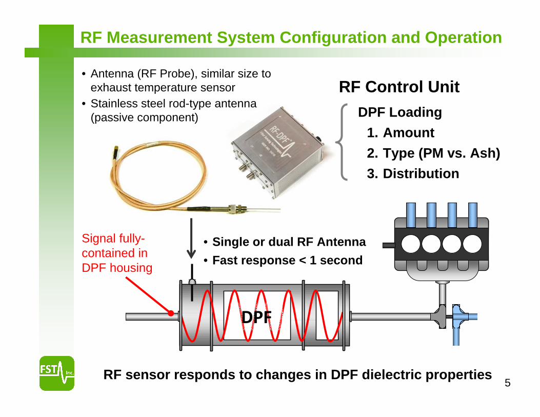
DPF
DPF Loading
1. Amount
2. Type (PM vs. Ash)
3. Distribution
• Single or dual RF Antenna
• Fast response < 1 second
RF sensor responds to changes in DPF dielectric properties
Signal fully-contained in DPF housing
• Antenna (RF Probe), similar size to exhaust temperature sensor
• Stainless steel rod-type antenna (passive component)
RF Measurement System Configuration and Operation
RF Control Unit
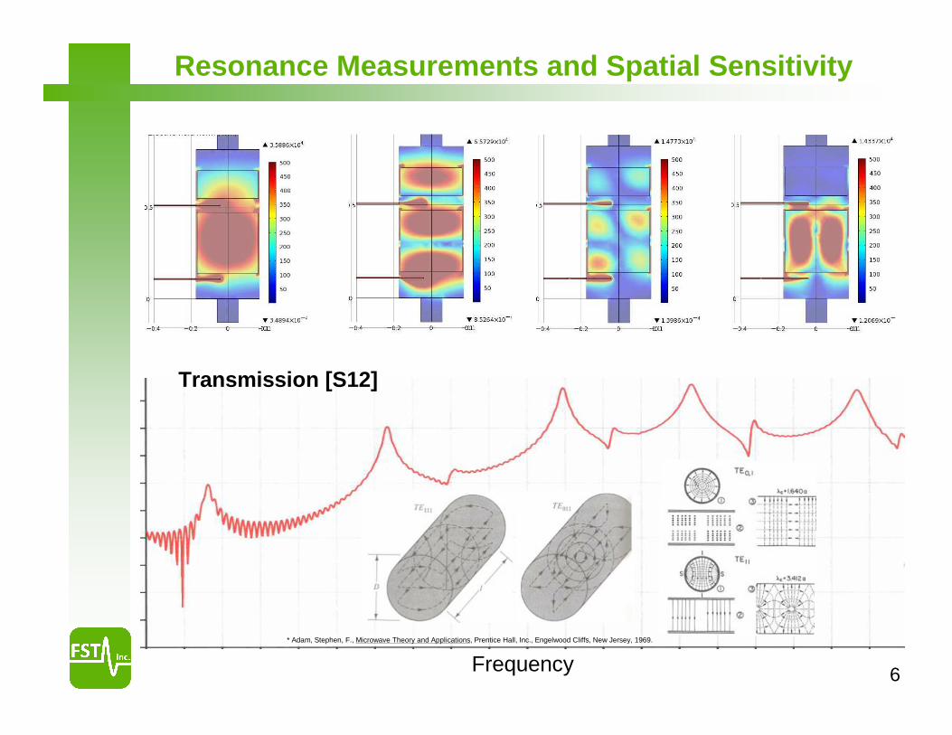
6Frequency
Transmission [S12]
* Adam, Stephen, F., Microwave Theory and Applications, Prentice Hall, Inc., Engelwood Cliffs, New Jersey, 1969.
Resonance Measurements and Spatial Sensitivity

7
Motivation: Aftertreatment Controls Optimization
Total FEP (Ref)
Regeneration Interval
Fu
el P
enal
ty
Total FEP ∆PR
egen
erat
ion
• Direct measure of loading state – advanced feedback controls.
• Additional advantages with alternative fuels and advanced combustion
• Adaptive controls as system ages (ash accumulation)
• Applications for OBD
Concept: Apply inexpensive radio frequency (RF) technologies to directly monitor DPF soot and ash levels and distribution with low-∆P DPF materials.
RF Sensors
DP
F
DO
C
ATS Controller
ECU
Motivation: Enable reduced energy consumption, cost, and increased durability of particulate filter systems through improved sensing and controls.
RF Sensing
DPF Materials
Advanced Controls
8
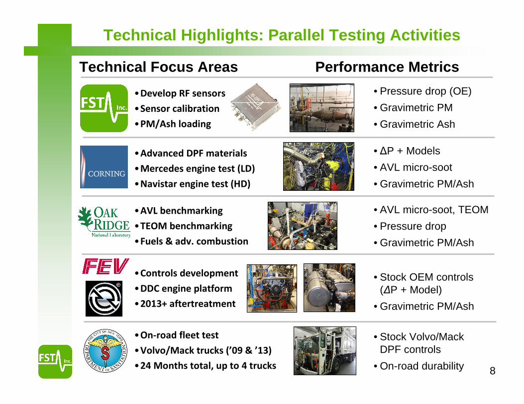
Technical Highlights: Parallel Testing Activities
• Pressure drop (OE)
• Gravimetric PM
• Gravimetric Ash
• ∆P + Models
• AVL micro-soot
• Gravimetric PM/Ash
• AVL micro-soot, TEOM
• Pressure drop
• Gravimetric PM/Ash
• Stock OEM controls (∆P + Model)
• Gravimetric PM/Ash
• Stock Volvo/Mack DPF controls
• On-road durability
•Develop RF sensors
•Sensor calibration
•PM/Ash loading
•Advanced DPF materials
•Mercedes engine test (LD)
•Navistar engine test (HD)
•AVL benchmarking
•TEOM benchmarking
•Fuels & adv. combustion
•Controls development
•DDC engine platform
•2013+ aftertreatment
•On-road fleet test
•Volvo/Mack trucks (’09 & ’13)
•24 Months total, up to 4 trucks
Technical Focus Areas Performance Metrics
9
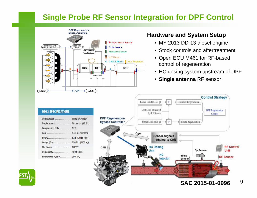
Single Probe RF Sensor Integration for DPF Control
Hardware and System Setup• MY 2013 DD-13 diesel engine
• Stock controls and aftertreatment
• Open ECU M461 for RF-based control of regeneration
• HC dosing system upstream of DPF
• Single antenna RF sensor
SAE 2015-01-0996
10
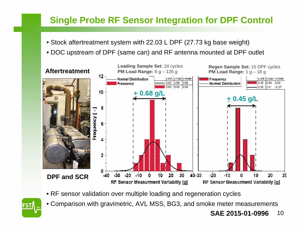
Single Probe RF Sensor Integration for DPF Control
Loading Sample Set: 24 cyclesPM Load Range: 6 g – 126 g
+ 0.68 g/L+ 0.45 g/L
Regen Sample Set: 15 DPF cyclesPM Load Range: 1 g – 18 gAftertreatment
DPF and SCR
• Stock aftertreatment system with 22.03 L DPF (27.73 kg base weight)
• DOC upstream of DPF (same can) and RF antenna mounted at DPF outlet
• RF sensor validation over multiple loading and regeneration cycles
• Comparison with gravimetric, AVL MSS, BG3, and smoke meter measurements
SAE 2015-01-0996
11
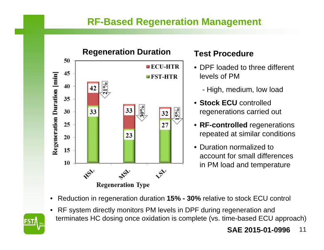
RF-Based Regeneration Management
• Reduction in regeneration duration 15% - 30% relative to stock ECU control
• RF system directly monitors PM levels in DPF during regeneration and terminates HC dosing once oxidation is complete (vs. time-based ECU approach)
Regeneration Duration Test Procedure
• DPF loaded to three different levels of PM
- High, medium, low load
• Stock ECU controlled regenerations carried out
• RF-controlled regenerations repeated at similar conditions
• Duration normalized to account for small differences in PM load and temperature
SAE 2015-01-0996
12E
GR
Turbo
DPF
DO
C
TEOMΔΔΔΔP, T
RF Control Unit
EG
R
Turbo
DPF
DO
C
TEOMΔΔΔΔP, T
RF Control Unit
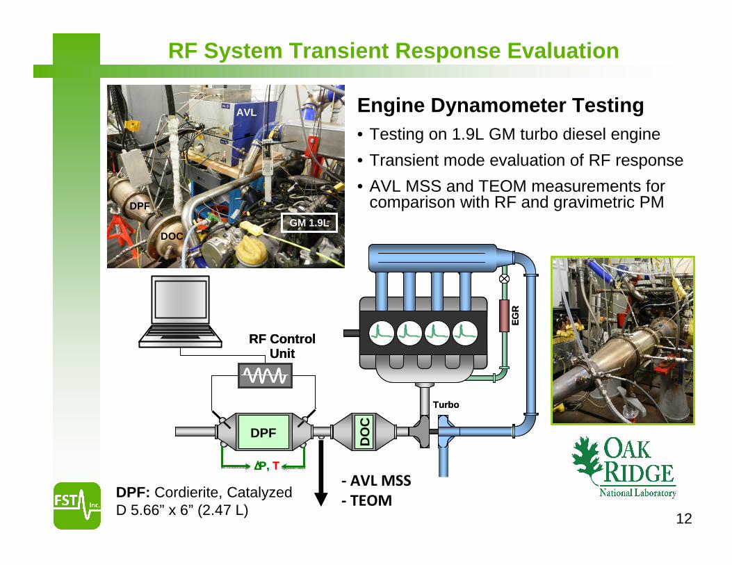
RF System Transient Response Evaluation
Engine Dynamometer Testing• Testing on 1.9L GM turbo diesel engine
• Transient mode evaluation of RF response
• AVL MSS and TEOM measurements for comparison with RF and gravimetric PM
DPF: Cordierite, Catalyzed D 5.66” x 6” (2.47 L)
GM 1.9L
DPF
DOC
AVL
- AVL MSS
- TEOM

13
GM 1.9L
DPF
DOC
AVL
9.6
9.7
9.8
9.9
10
10.1
10.2
10.3
10.4
10.5
10.6
10.7
11:54 11:57 12:00 12:02 12:05 12:08 12:11 12:14 12:17 12:20
RF
Sig
nal (
RA
W)
-5
0
5
10
15
20
25
30
35
40
RF
AVL MSS Intergal
TEOM
60
65
70
75
80
85
90
95
100
11:54 11:57 12:00 12:02 12:05 12:08 12:11 12:14 12:17 12:20
Time [hh:mm]
0
20
40
60
80
100
MAF (EGR)
Torque
• Testing on 1.9L GM turbo-diesel at ORNL
• Catalyzed cordierite DPF
• 1 Hz sampling rate for AVL MSS and TEOM
• 2.5 Hz sampling rate for RF sensor
MA
F [
kg/h
r]R
F S
ign
al [
RA
W]
TE
OM
PM
[µ
g],
AV
L P
M (
inte
gra
ted
, mg
)T
orq
ue
[ft-
lb]
RF slope change due to EGR steps
12
34
5
-0.05
0.00
0.05
0.10
0.15
11:54 11:57 12:00 12:03 12:06 12:09
Time [hh:mm]
RF
Par
amet
er R
ate
-20
0
20
40
60
80
100
120
140
Soo
t [m
g/m
^3]
RF Differential
AVL MSS
1 23
4
5
RF
AVL MSS
Fast transient response to small changes in engine-out PM
Transient Response Well-Correlated with AVL MSS
14
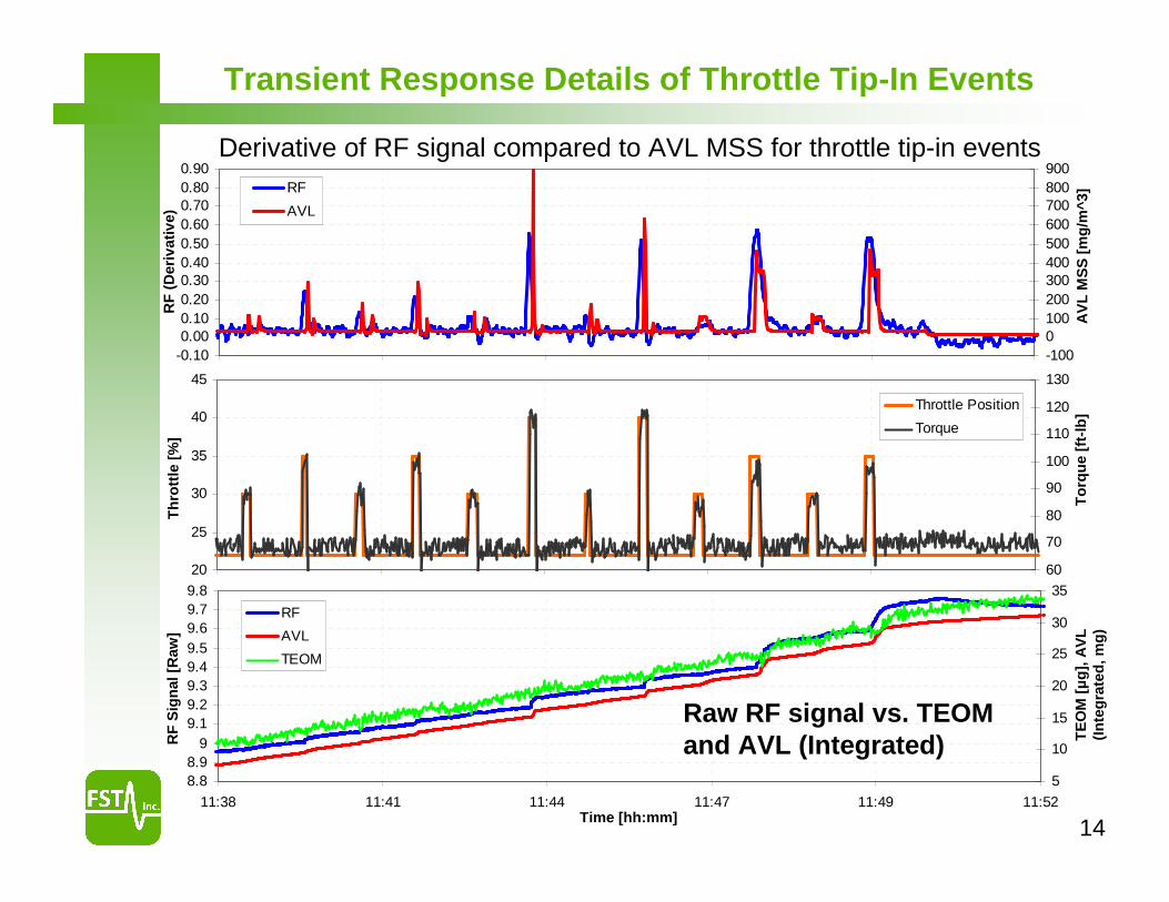
Transient Response Details of Throttle Tip-In Events
-0.100.000.100.200.300.400.500.600.700.800.90
-1000100200300400500600700800900
RF
AVL
20
25
30
35
40
45
60
70
80
90
100
110
120
130
Throttle Position
Torque
8.88.9
99.19.29.39.49.59.69.79.8
11:38 11:41 11:44 11:47 11:49 11:52
5
10
15
20
25
30
35
TE
OM
PM
[ug
], A
VL
MS
S
RF
AVL
TEOM
Derivative of RF signal compared to AVL MSS for throttle tip-in events
Time [hh:mm]
To
rqu
e [f
t-lb
]T
EO
M [µ
g],
AV
L
(In
teg
rate
d, m
g)
AV
L M
SS
[m
g/m
^3]
RF
(D
eriv
ativ
e)T
hro
ttle
[%
]R
F S
ign
al [
Raw
]
Raw RF signal vs. TEOM and AVL (Integrated)
15
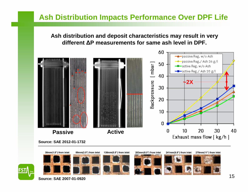
Ash Distribution Impacts Performance Over DPF Life
Ash distribution and deposit characteristics may result in very different ∆P measurements for same ash level in DPF.
Passive Active
Source: SAE 2012-01-1732
Source: SAE 2007-01-0920
~2X
16
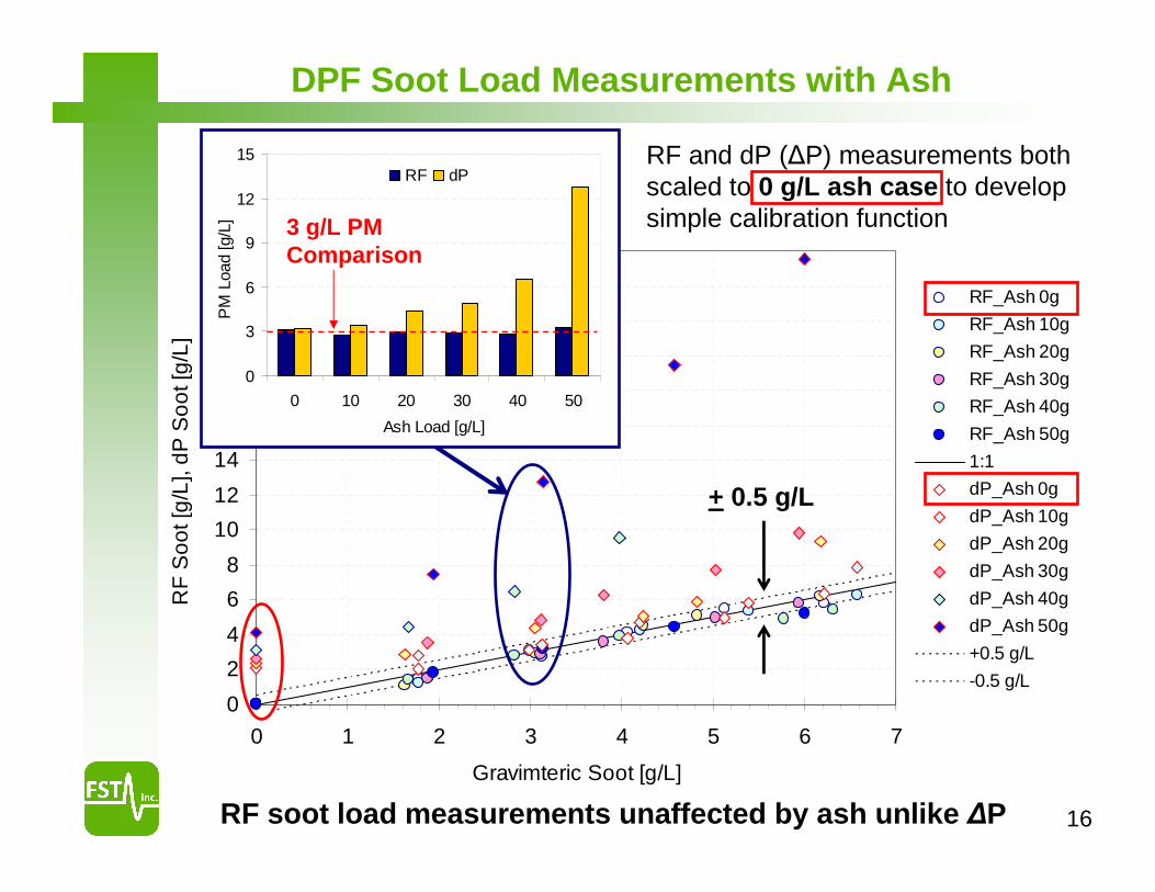
DPF Soot Load Measurements with Ash
0
2
4
6
8
10
12
14
16
18
20
22
24
26
0 1 2 3 4 5 6 7
Gravimteric Soot [g/L]
RF
Soo
t [g
/L],
dP
So
ot [
g/L
]
RF_Ash 0g
RF_Ash 10g
RF_Ash 20g
RF_Ash 30g
RF_Ash 40g
RF_Ash 50g
1:1
dP_Ash 0g
dP_Ash 10g
dP_Ash 20g
dP_Ash 30g
dP_Ash 40g
dP_Ash 50g
+0.5 g/L
-0.5 g/L
+ 0.5 g/L
RF and dP (∆P) measurements both scaled to 0 g/L ash case to develop simple calibration function
RF soot load measurements unaffected by ash unlike ∆P
0
3
6
9
12
15
0 10 20 30 40 50
Ash Load [g/L]
PM
Loa
d [g
/L]
RF dP
3 g/L PM Comparison
17
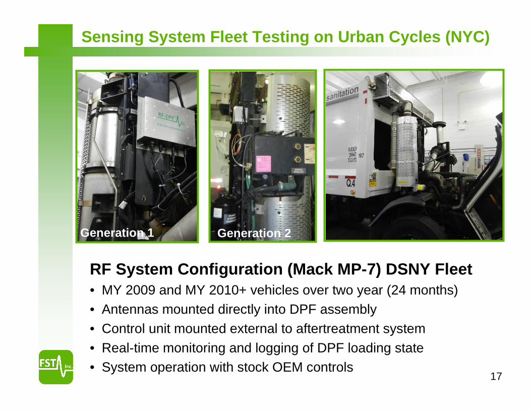
RF System Configuration (Mack MP-7) DSNY Fleet• MY 2009 and MY 2010+ vehicles over two year (24 months)• Antennas mounted directly into DPF assembly• Control unit mounted external to aftertreatment system• Real-time monitoring and logging of DPF loading state• System operation with stock OEM controls
Sensing System Fleet Testing on Urban Cycles (NYC)
Generation 1 Generation 2
18
0%
10%
20%
30%
40%
50%
60%
70%
80%
90%
100%
0 1000 2000 3000 4000 5000 6000 7000 8000 9000
Time [min]
RF
Soo
t [%
]
0
100
200
300
400
500
600
700
800
900
Tem
pera
ture
[C]
RF-DPF [%] T_avg [C]
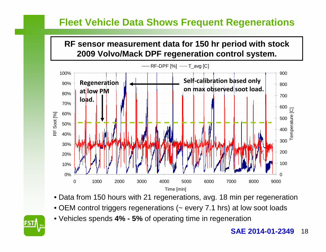
RF sensor measurement data for 150 hr period with stock 2009 Volvo/Mack DPF regeneration control system.
Regeneration
at low PM
load.
• Data from 150 hours with 21 regenerations, avg. 18 min per regeneration• OEM control triggers regenerations (~ every 7.1 hrs) at low soot loads• Vehicles spends 4% - 5% of operating time in regeneration
Fleet Vehicle Data Shows Frequent Regenerations
Self-calibration based only
on max observed soot load.
SAE 2014-01-2349
19
0%
10%
20%
30%
40%
50%
60%
70%
80%
90%
100%
0 25 50 75 100 125 150 175 200
0
100
200
300
400
500
600
700
800
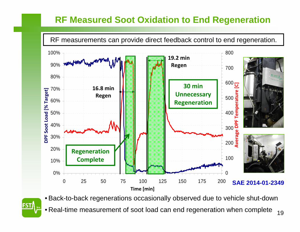
• Back-to-back regenerations occasionally observed due to vehicle shut-down
• Real-time measurement of soot load can end regeneration when complete
16.8 min
Regen
19.2 min
Regen
30 min
Unnecessary
Regeneration
Regeneration
Complete
DP
F S
oo
t Lo
ad
[%
Ta
rge
t]
Av
era
ge
DP
F T
em
pe
ratu
re [
C]
Time [min]
RF Measured Soot Oxidation to End Regeneration
RF measurements can provide direct feedback control to end regeneration.
SAE 2014-01-2349
20
Summary and Technical Highlights
Outlook and Additional Applications• Current work focused on controls optimization and sensor validation in a
range of light-duty and heavy-duty applications with project partners.
• Additional opportunities for GPF and catalyst applications to monitor gas species adsorbed on catalysts
Demonstrated direct measurement of DPF soot and ash levels via RF sensing in test cell and vehicle applications.
Technical Highlights
• Developed single antenna RF system and demonstrated high level of accuracy for DPF soot level measurements
• Demonstrated combined DPF soot AND ash measurements
• RF transient response well-correlated with AVL micro-soot sensor
• Demonstrated fast sensor response < 1 second
• Evaluated RF performance over 380,000 mile equivalent DPF aging
• Fuel savings potential via extend regeneration interval and reduced regeneration duration relative to stock OEM controls
21
Acknowledgements
This material is based upon work supported by the Department of Energy DE-EE0005653.
• Roland Gravel, Ken Howden, and Gurpreet Singh from the DOE
• Ralph Nine, Trevelyn Hall, and David Ollett from NETL
Disclaimer: This report was prepared as an account of work sponsored by an agency of the United States Government. Neither the United States Government nor any agency thereof, nor any of their employees, makes any warranty, express or implied, or assumes any legal liability or responsibility for the accuracy, completeness, or usefulness of any information, apparatus, product, or process disclosed, or represents that its use would not infringe privately owned rights. Reference herein to any specific commercial product, process, or service by trade name, trademark, manufacturer, or otherwise does not necessarily constitute or imply its endorsement, recommendation, or favoring by the United States Government or any agency thereof. The views and opinions of authors expressed herein do not necessarily state or reflect those of the United States Government or any agency thereof.
Commercial and National Laboratory Project Partners
• Corning Incorporated
• Oak Ridge National Laboratory
• Daimler Trucks NA / Detroit Diesel
• FEV
• DSNY