real time iris recognition systemeprints.utar.edu.my/545/1/mh-2012-0806075-1.pdf · real time iris...
TRANSCRIPT

REAL TIME IRIS RECOGNITION SYSTEM
SIM TZE HENG
A project report submitted in partial fulfilment of the
requirements for the award of Bachelor of Engineering
(Hons.) Mechatronics Engineering
Faculty of Engineering and Science
Universiti Tunku Abdul Rahman
April 2012

ii
DECLARATION
I hereby declare that this project report is based on my original work except for
citations and quotations which have been duly acknowledged. I also declare that it
has not been previously and concurrently submitted for any other degree or award at
UTAR or other institutions.
Signature : _________________________
Name : _________________________
ID No. : _________________________
Date : _________________________

iii
APPROVAL FOR SUBMISSION
I certify that this project report entitled “REAL TIME IRIS RECOGNITION
SYSTEM” was prepared by SIM TZE HENG has met the required standard for
submission in partial fulfilment of the requirements for the award of Bachelor of
Engineering (Hons.) Mechatronics Engineering at Universiti Tunku Abdul Rahman.
Approved by,
Signature : _________________________
Supervisor : Mr Chai Tong Yuen
Date : _________________________

iv
The copyright of this report belongs to the author under the terms of the
copyright Act 1987 as qualified by Intellectual Property Policy of University Tunku
Abdul Rahman. Due acknowledgement shall always be made of the use of any
material contained in, or derived from, this report.
© 2012, Sim Tze Heng. All right reserved.

v
REAL TIME IRIS RECOGNITION SYSTEM
ABSTRACT
The objective of this project is to develop a robust automated algorithm for real time
iris detection in higher level security purpose with high recognition rates in varying
environment. First, Haar cascade based algorithm has been applied for fast and
simple face detection from the input image. The face image is then being converted
into grayscale image. After that, the iris candidates are extracted from the intensity
valleys from the detected face. Costs of each iris candidates are calculated. Finally
the iris candidates are paired up and the cost of each possible pairing is computed by
a combination of mathematical models. After that, these irises pair will be treat as
information for system to continue the tracking it in the continuous frame. The
novelty of this work is that the algorithm works on complex images without
constraints on the background or surrounding lighting. This algorithm has achieved
high success rate of automatically iris recognition when the system have more online
based positive example that generated during the tracking process under user friendly
real time environment.

vi
TABLE OF CONTENTS
DECLARATION ii
APPROVAL FOR SUBMISSION iii
ABSTRACT v
TABLE OF CONTENTS vi
LIST OF TABLES viii
LIST OF FIGURES ix
CHAPTER
1 INTRODUCTION 1
1.1 Background 1
1.2 Aims and Objectives 2
1.3 Organization of the report 3
2 LITERATURE REVIEW 4
2.1 Introduction 4
2.2 Face Region Detection 4
2.3 Eye Detection 6
2.3.1 Eye Localization 9
2.4 Iris Localization 10
2.5 Iris Tracking 11
3 METHODOLOGY 14
3.1 Introduction 14
3.2 Face Region Detection (Preprocessing) 14

vii
3.3 Iris Detection 16
3.3.1 Extraction of valley in the face region 16
3.3.2 Detection of iris candidates 17
3.3.3 Selecting the irises of both eyes 18
3.4 Iris Tracking 21
3.5 Summary 25
4 RESULT AND DISCUSSION 26
4.1 Result and Discussion 26
5 CONCLUSION 53
5.1 Conclusion 53
6 RECOMMENDATIONS AND FUTURE IMPROVEMENTS 54
6.1 Recommendations and Future Improvements 54
REFERENCES 59

viii
LIST OF TABLES
TABLE TITLE PAGE
4.1 Test Result of before and after add the initial
bounding box of Video Set 1 and 2 29
4.2 Compare the success and the fail case before and
after tracking of the Video Set 1 and 2 31
4.3 The tracking result time in tracking both irises and
one iris only 44

ix
LIST OF FIGURES
FIGURE TITLE PAGE
2.1 Haar-like simple features: (a) edge features; (b)
line features 6
2.2 The low-cost prototype with scene camera (left one)
and eye camera and IR LED (right one) (Schneider,
N., E. Barth, P. Bex, and M. Dorr, 2011) 7
2.3 The structure of eye detector proposed by J.B. Kim,
S.C. Kee and J.Y. Kim (2005) 7
2.4 Eye detection using template matching 8
2.5 Proposed Method of Iris Detection and
Localization (Rupal Khilari, 2010) 11
2.6 The masks of dimension (2·Rmax+1)×(2·Rmax+1)
that are convoluted with the gradient image used in
the T. D’Orazio et al. case 12
3.1 Haar-like features 15
3.2 Eye template 17
3.3 An 2bit Binary Patterns example showed in the
Zdenek Kalal paper. Features encode local gradient
orientation within the object bounding box. 23
3.4 Example of a trajectory of a detected object
represents a structure in video (Zdenek Kalal, 2010)
23
3.5 The online model is initialized in the first frame by
the manually selected It is expanding by “growing
x
events”, refined by “pruning events” and slowly
converges toward the unknown object manifold. 24
4.1 Pixel axis 27
4.2 An example of narrow down the iris candidates
pair by a initial bounding box with some parameter
setting (a) success case (b) fail case 27
4.3 Before adding bounding box. First row showed
some example of out of the frame images. Second
row showed some sample of incorrect result. 30
4.4 The Video Set 1 result of the TLD in different
frame (a) 2nd frame, (b) 60th frame, (c) 143th
frame, (d) 191th frame, (e) 208th frame and (f)
230th frame. 32
4.5 The Video Set 2 result of the TLD in different
frame (a) 190th frame, (b) 195th frame, (c) 212th
frame, (d) 255th frame, (e) 263th frame and (f)
315th frame. 33
4.6 Positive example 34
4.7 The tracking result when the user face have some
obstacle (without spectacle) 35
4.8 The user having different eye gaze (with spectacle)
during the system testing 36
4.9 The user having different eye gaze (without
spectacle) during the system testing 37
4.10 The user looking up and down during the system
testing 38
4.11 The user try to make the head/ face out of the
frame and come back again during the system
testing 39
4.12 User try to tilt his head during the system testing 40
4.13 Another user try to capture his face when another
is leaving during the system testing 41
xi
4.14 Blocking with other user when another is tracking
his face during the system testing 42
4.15 The user try to allocate the head/ face in different
region of the camera frame during the system
testing 43
4.16 The result frame in tracking both irises and one iris
only testing 45
4.17 Different pixel size frame of Video Set 4. Left one
is 160*120 pixel and right one is 320*240 pixel 46
4.18 Time against the frame graph of tracking among
820 frames of Video Set 4 in 320x240 and
160x120 pixel size. 47
4.19 Different facial expression 48
4.20 Obstacle at the user's face 49
4.21 Close eye 50
4.22 Fail case samples 51
6.1 User who wearing spectacle have hard time to
detect the irises. First row showed some example
of deflect irises pair result. Second row showed
some sample of accuracy result that happen rarely
at the initial tracking. 55
6.2 Processing flow on CUDA (www.nvidia.com) 56
6.3 Example of an eyetracking "heatmap"
(http://www.useit.com/eyetracking/) 57

CHAPTER 1
1 INTRODUCTION
1.1 Background
The first use of iris recognition can trace back to the Paris's prison in eighteenth
century, where police discriminated criminal by inspecting the colour of their irises
(Y.P Huang , S.W Luo and E.Y. Chen ,2002). Until 1987, an idea of automated iris
recognition was proposed. (Flom and Safir , 1987).
In particular, the biomedical literature suggests that irises are as distinct as
fingerprints or patterns of retinal blood vessels. Further, since the iris is an overt
body, its appearance is amenable to remote examination with the aid of a machine
vision system.
Among these biometric technologies, iris recognition becomes a hot topic in
pattern recognition and machine learning research area because of the following
advantages:
1) The iris begins to form in the third month of gestation and the structures
creating its pattern are largely complete by the eighth month, then does not
change after two or three years (Kronfeld,1962)
2) It is suggested in recent years that human irises might be as distinct as
fingerprint for different individuals, leading to the idea that iris patterns may
contain unique identifications features. (El-Bakry, H.M, 2001)

2
3) The forming of iris depends on the initial environment of embryo, so the iris
texture patterns don’t correlate with genetic determination (John
Daugman,1997) Even the left and right irises for a given person are different
from each other (El-Bakry, H.M, 2001)
4) The inner organs of iris are protected by aqueous humor and cornea from the
environment.
5) It is almost impossible that irises are modified by surgical without risk.
6) The iris recognition is non-invasive and don’t cause the damage to identifier.
The iris recognition has so many advantages that a lot of attentions are
attracted
Nowadays, iris detection is an hot topic in computer vision with application
in some are like: biometric, human computer interaction/ human machine interface,
security or even driver's drowsiness detection system.
1.2 Aims and Objectives
The aim of this research is to increase the performance of iris detection in real-time
in varying environment conditions. After that, construct a robust automatic tracking
system for the irises.
The objective of this project is to:
Develop a robust automated algorithm for higher security purpose iris detection
and tracking in real time.
Validate and optimize the proposed algorithm in different environments.
Reduce the effects of excessive illumination and head tilts which have affected
the performance of iris recognition.

3
1.3 Organization of the report
In Chapter 1 (Introduction) of this report is mainly brief on the background, the
usage and how importance of iris recognition. Then the aims and objectives are
indicated. Finally the structural organization of the report instructed out.
Chapter 2 (Literature Review), investigates and studies the existing technique
about the iris detection or iris detection. This information used as a guideline in
organizing the methodology of the project.
Chapter 3 (Methodology), presented the procedures and methods chosen to
develop the project and to ensure that the aims and objectives of the research are met.
This chapter show the research work done and discuss the theories and equations of
the proposed algorithm.
Chapter 4 (Result and Discussions), show the result of the system using some
case photos. Also, the result analysis will be discuss in here.
Chapter 5 (Conclusion), summaries the overall project result in simply way.
Chapter 6 (Recommendations and Future Improvements), suggests some
ideas or methods that can improve and advance this project in the future.

CHAPTER 2
2 LITERATURE REVIEW
2.1 Introduction
The literature review of the project is based on face region detection, eye detection
and tracking methods.
2.2 Face Region Detection
The first step of iris detection is the face region detection. In RGB space, a triple
[r,g,b] represents not only the colour but also the brightness. As J. Yang and
A.Waibel (1996) mention that is possible to remove brightness from the skin-colour
representation, while preserving an accurate, but low dimensional colour information.
It also said that the skin colour can be represented in the chromatic colour space
under the normal lighting condition since the brightness is not important for
characterizing skin colours. From the investigation of the face colour cluster by
J.Yang and A.Waibel (1996) discovered that the distribution has a regular shape and
the skin colour distributions of different people under different lighting conditions in
the chromatic colour space have similar Gaussian distributions.
The proposed algorithm first create skin colour model for the face region
detection from colour input images and denotes a colour vector in RGB colour space.
This method using the rg colour space creates a skin colour model by the following
step:

5
I. Select the regions that known to represent skin from the input colour images.
II. Estimate the mean m and the covariance matrix Σ of the colour distribution in
the chromatic colour space.
III. Substitute those parameter into the Gaussian distribution
IV. To detect the face region using following procedure, select pixels (x,y) whose
colour values satisfy . The selected pixels are called the
skin colour pixels.
V. Apply squares of sizes 5 x 5 closing and 9 x 9 opening mathematical
morphologies to the regions of skin colours pixels as structuring elements.
VI. Find a connected component of skin colour pixels with the largest area.
VII. Let denotes the coordinates of the pixels in the connected component
obtained by the last step. And, let and be the smallest and the largest of
and be the smallest of . Then, give the face region by the square
produced by two vertical lines and and two horizontal lines
and .
Meanwhile, AdaBoost is a very effective learning algorithm that organizes
simple and fast weak classifiers as a weighted sum and renders a fast strong classifier
having a high success rate. This algorithm was first proposed by Freund and Schapire
(1996) and it became popular in the face detection field after Viola and Jones (2001).
To implement multi-view face detection and eye detection, J.B. Kim, S.C.
Kee and J.Y. Kim (2005) had adopted Freund and Schapire (1996)’s gentle In
AdaBoost, N examples are provided and weights them to .Repeat for time and
find a weak classifier . Set and renormalize
weights and lastly output the classifier
6
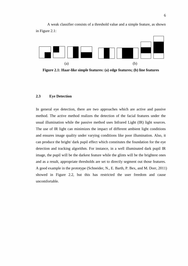
A weak classifier consists of a threshold value and a simple feature, as shown
in Figure 2.1:
(a) (b)
Figure 2.1: Haar-like simple features: (a) edge features; (b) line features
2.3 Eye Detection
In general eye detection, there are two approaches which are active and passive
method. The active method realizes the detection of the facial features under the
usual illumination while the passive method uses Infrared Light (IR) light sources.
The use of IR light can minimizes the impact of different ambient light conditions
and ensures image quality under varying conditions like poor illumination. Also, it
can produce the bright/ dark pupil effect which constitutes the foundation for the eye
detection and tracking algorithm. For instance, in a well illuminated dark pupil IR
image, the pupil will be the darkest feature while the glints will be the brightest ones
and as a result, appropriate thresholds are set to directly segment out those features.
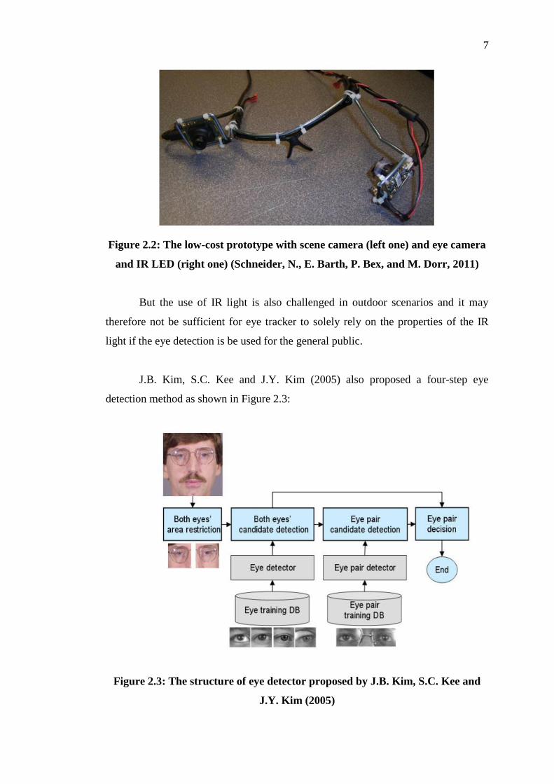
A good example in the prototype (Schneider, N., E. Barth, P. Bex, and M. Dorr, 2011)
showed in Figure 2.2, but this has restricted the user freedom and cause
uncomfortable.
7
Figure 2.2: The low-cost prototype with scene camera (left one) and eye camera
and IR LED (right one) (Schneider, N., E. Barth, P. Bex, and M. Dorr, 2011)
But the use of IR light is also challenged in outdoor scenarios and it may
therefore not be sufficient for eye tracker to solely rely on the properties of the IR
light if the eye detection is be used for the general public.
J.B. Kim, S.C. Kee and J.Y. Kim (2005) also proposed a four-step eye
detection method as shown in Figure 2.3:
Figure 2.3: The structure of eye detector proposed by J.B. Kim, S.C. Kee and
J.Y. Kim (2005)
8
Although in those proposed methods get high performance on face and eye
detection, but it needs a huge image database to hit the high success rate. In this case,
the database has around 17,000 face images, include frontal database and non-frontal
database.
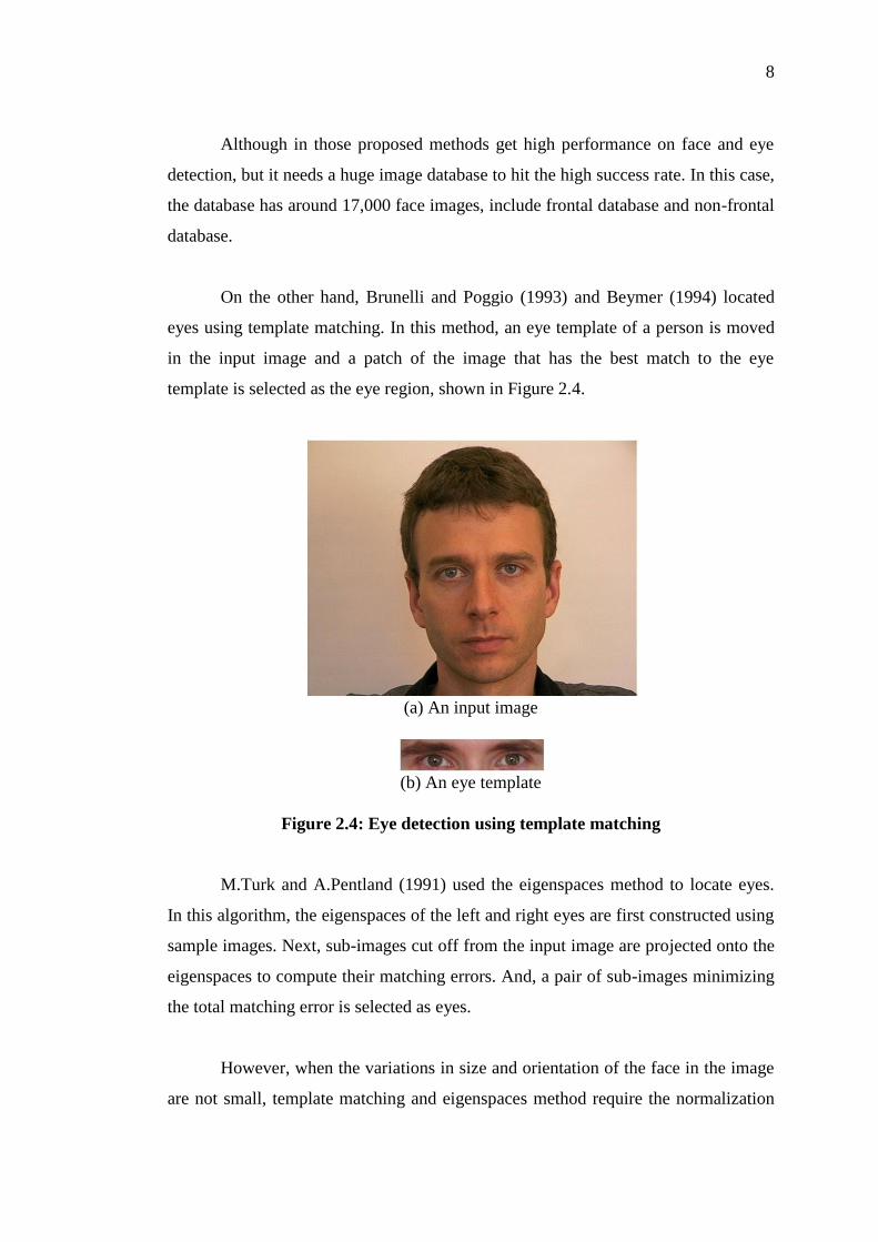
On the other hand, Brunelli and Poggio (1993) and Beymer (1994) located
eyes using template matching. In this method, an eye template of a person is moved
in the input image and a patch of the image that has the best match to the eye
template is selected as the eye region, shown in Figure 2.4.
(a) An input image
(b) An eye template
Figure 2.4: Eye detection using template matching
M.Turk and A.Pentland (1991) used the eigenspaces method to locate eyes.
In this algorithm, the eigenspaces of the left and right eyes are first constructed using
sample images. Next, sub-images cut off from the input image are projected onto the
eigenspaces to compute their matching errors. And, a pair of sub-images minimizing
the total matching error is selected as eyes.
However, when the variations in size and orientation of the face in the image
are not small, template matching and eigenspaces method require the normalization

9
of the face in its size and orientation because these algorithms use sample eye images
as eye models. In addition, these algorithms can correctly detect only eye patterns
that are similar to sample eye images used as eye models.
Also, there have a few researches use Hough Transform to detect the irises of
both eyes (Y.Tian. T.Kanade and J.F. Cohn, 2000). However, the iries are
considerably small compared to the facial input image, so it is quite difficult to
correctly detect the both irises by directly apply Hough Transform to whole face
region.
2.3.1 Eye Localization
In the paper "In the Eye of the Beholder: A Survey of Models for Eyes and Gaze"
(D.Hansen & Q.Ji, 2010) mention that the eye localization methods have been
classified into five main categories:
[1] Shape-based Approaches
Described by its shape, which includes the iris and pupil contours and
the exterior shape of the eye (eyelids).
[2] Feature-Based Shape Methods
Explore the characteristics of the human eye to identify a set of
distinctive features around the eyes. The limbus, pupil (dark/bright
pupil images) and cornea reflections are common features used for
eye localization.
[3] Appearance-Based Methods
Detect and track eyes directly, based on the photometric appearance
as characterized by the colour distribution or filter responses of the
eye and its surroundings. These methods are independent of the actual
object of interest and are in principle capable of modeling other
objects besides eyes.

10
[4] Hybrid Models
Aim at combining the advantages of different eye-models within a
single system to overcome their respective shortcomings.
[5] Other Methods
Employing temporal information and active light.
The first task of an HCI system is to locate the operating feature, in this case,
the eyes. Research work in the area of eye localization has been presented by Spors
and Rabenstein (2001), who proposed the use of Principal Component Analysis
(PCA) for the eye localization.
2.4 Iris Localization
For local the iris in the image, (Rupal Khilari, 2010) using the Circular Hough
Transform (CHT) to discover the shape of the iris form the image after the Canny
edge detection. Canny detector is choose because it produces a more precise, finer
edge with lesser noise. Then, the Bresenham's circle drawing algorithm is adopted to
draw a complete circle. When every edge point and every desired radius is used, the
accumulator images are analyzed and contain number corresponding to the number
of circle passing through the individual coordinates. At the end, the highest numbers
correspond to the centre of the most probable circle in the image. Author also
mention that modified Hough Transform is prefer than the standard weighted
Circular Hough Transform to detect the iris for reducing the effect of the eyelids and
eyelashes to result the final.

11
Figure 2.5: Proposed Method of Iris Detection and Localization (Rupal Khilari,
2010)
The further explain of Figure 2.5:
(a) The eye region
(b) The corresponding edge image after Canny edge detection
(c) A circular mask of various radii is passed over the largest value in
accumulator image and the average over the area is computed.
(d) The resultant iris detection (blue circle) using the modied weighted Circular
Hough Transform.
(e,f,g,h) Accumulator images using Bresenham's circle drawing algorithm
(intensity uniformly scaled), with radii 6,7,8,9 pixels respectively.
Kourkoutis et al. (2007) proposed another approach for iris localization have
perform good accuracy and computational time. This procedure is based on the
observation that the chrominance component Cr (from YCbCr) takes very low values
in the eye area, compared to the areas covered by skin. However, this system
performs colour images and must be manually calibrated by defining several
parameters.
2.5 Iris Tracking
To detect and track the eyes in a complex background environment, the feature of the
eye are used. In real time state-of-the art object detectors are typically based on the

12
AdaBoost (Yoav Freud and Robert Schapire, 1999) algorithm. They require large
training sets and are computationally expensive to train. This approach is not
applicable for the online setting. Freund and Schapire (1997) stated that the actual
performance of boosting on a particular problem is clearly dependent on the data and
the weak learner. Consistent with theory, boosting can fail to perform well given
insufficient data, overly complex weak hypotheses, or weak hypotheses that are too
weak. Boosting seems to be especially susceptible to noise.
Existing online detectors (Helmut Grabner and Horst Bischof, 2006) enable
efficient training but their purpose is to “adapt” to new samples and gradually
dismiss the old ones.
T. D’Orazio et al. (2004) used a new circle detection operator that is based on
the directional Circle Hough Transform based on convolutions applied to the edge
image. Figure 2.6 is the mask represent in each point the direction of the radial vector
scaled by the distance from the centre in a ring with minimum radius Rmin, and
maximum radius Rmax. The convolution between the gradient images and these
masks evaluates how many points in the image have the gradient direction
concordant with the gradient direction of a range of circles. The maximal value of the
convolution result gives the candidate centre of the circle in the image.
Figure 2.6: The masks of dimension (2·Rmax+1)×(2·Rmax+1) that are
convoluted with the gradient image used in the T. D’Orazio et al. case
Also, Perez et al. (2007) described a real-time iris detection method based on
coronal-Axis-Rotated Faces. The method is based on anthropometric templates

13
applied to detect the face and eyes. The templates use key features of the face such as
the elliptical shape, and location of the eyebrows, nose, and lips. For iris detection, a
template following the iris–sclera boundary shape is used. However, they assume
that there is always a high contrast between iris and the sclera.

CHAPTER 3
3 METHODOLOGY
3.1 Introduction
This chapter describes the implementation of the proposed algorithm from its
theoretical models. Hence the methodology has shown how the different
mathematical models are combined to achieve the research objectives. There is few
phase in this proposed real time iris detection system: Face Region Detection, Valley
Detection, Iris Candidate Detection, Iris Candidate Selection, Iris candidates pair
selection and TLD (Tracking-Learning-Detection)
3.2 Face Region Detection (Preprocessing)
First of all, get the input images from the webcam or a video file and crop the
head or face region for further processing. In this phase, OpenCV Haar Cascade
based face detector has been choose to use for real time detection instead of the skin
colour based face detector. This is because the RGB colour based face detection
tends to be affected easily by the surrounding lighting variation and complex
background and it not suitable for real time implementation (T.Y.Chai, M.Rizon and
M.Suhzri, 2009). The Haar like features trains classifiers with a few thousands of
sample view images of object and construct a cascade of classifiers to detect the eye
rapidly. It is specified by its shape, position and the scale. Figure 3.1 illustrated the
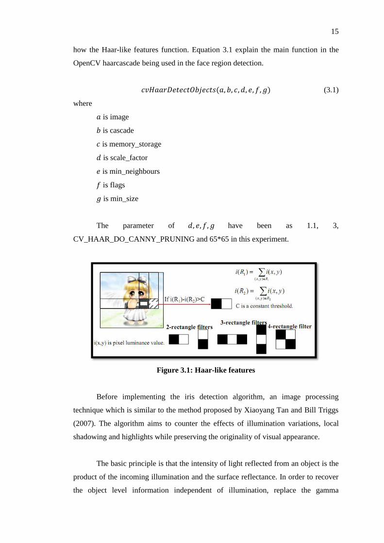
15
how the Haar-like features function. Equation 3.1 explain the main function in the
OpenCV haarcascade being used in the face region detection.
(3.1)
where
is image
is cascade
is memory_storage
is scale_factor
is min_neighbours
is flags
is min_size
The parameter of have been as 1.1, 3,
CV_HAAR_DO_CANNY_PRUNING and 65*65 in this experiment.
Figure 3.1: Haar-like features
Before implementing the iris detection algorithm, an image processing
technique which is similar to the method proposed by Xiaoyang Tan and Bill Triggs
(2007). The algorithm aims to counter the effects of illumination variations, local
shadowing and highlights while preserving the originality of visual appearance.
The basic principle is that the intensity of light reflected from an object is the
product of the incoming illumination and the surface reflectance. In order to recover
the object level information independent of illumination, replace the gamma
16
correction of the gray-level with where this parameter is defined by user with
. By this, it enhance the local dynamic range of the image in dark region
while compressing it in bright regions
3.3 Iris Detection
This section explains the detection of the iris from the input image in few steps:
valley extraction, detection of iris candidates and selection of iris candidates.
3.3.1 Extraction of valley in the face region
To extract valleys from the face region, the proposed algorithm first applies
grayscale closing (S.R. Sternberg, 1986) to the face region. For each pixel in
the face region, let
(3.2)
where
denotes its value obtained by applying grayscale closing and
denotes its intensity value
Then, the region consisting of pixels where is greater than or
equal to a threshold value, T is determined to be valleys. The threshold value was set
to the largest value T satisfying
(3.3)
where
N is the number of pixels in the face region;
MAX is the maximum of over all pixels in the face region;
is the number of pixels in the face region within

17
is a parameter given as input. (In the experiments, is set to 0.1for all
image)
Pre-processing steps such as histogram equalization and light spot deletion
are performed to enhance the quality of image and reduce illumination effect in this
algorithm.
3.3.2 Detection of iris candidates
After extracting the valley from the face region, the proposed algorithm performs the
similar method as T. Kawaguchi and M. Rizon (2003). First, it computes the costs
for all pixels in the valleys using the eye template as shown in Figure
3.1 with following equation 3.4
(3.4)
where
and are the mean crossing numbers of row j and column i
is the intensity difference between the central part and the boundary
parts of and
is a square region with center and side length d.
Then, the proposed algorithm selects m pixels according to non-increasing
order of to give the local maxima of . In the experiments, m was set to
20.
Figure 3.2: Eye template
After that, place the eye template at each candidate location and
measures the separability between two regions and using given Equation 3.5:
18
(3.5)
where
is the intensity values of pixels in the union of
is number of pixels in
is the average intensity in and
is the average intensity in the union of
Let denote the separability between two regions and in the
template with size r. Change the size r in the range of to find the
size r maximizing and determine it to be the radius of the iris candidate
centered at .
3.3.3 Selecting the irises of both eyes
In this section, the mathematical calculation of the selection of the iris separate into
two part. First calculate the cost of all the irises candidates, after that the iris
candidates are paired up and computed the cost of each possible pairing by a
combination of mathematical models.
3.3.3.1 Cost of iris candidates
First, applies the Canny edge detector to the face region and measures the fitness of
iris candidates to the edge image using the circular Hough transform as follow
(3.6)
where
is the circle center and r is the radius.

19
Select with the largest vote and denote the largest vote by
which is the vote for the iris candidate . Then, given an iris candidate
, measures the fitness of the iris candidates place the template in Figure 3.2
at the position on the intensity image and then compute the
separabilities , , and using Equation 3.5 where
denotes the separability between regions and (iris and eye region)
Finally, the proposed algorithm calculate the cost of each iris candidate by a
simple sum all the four costs as shown in Equation 3.7:
(3.7)
where
is the maximum of over all iris candidates
is the Hough transform vote for
is the average intensity inside and
is the average of over all iris candidates.
3.3.3.2 Costs for pairs of iris candidates
The proposed algorithm computes a cost for each pair of iris candidates and
such
and
where
L is the width of the left and right contours of the face in x-positions and
and is the length and orientation of the line segment connecting
and , respectively.
To place the iris candidates and to coincide the iris center of both eyes
in the iris template, the proposed algorithm applying affine transform to the input
20
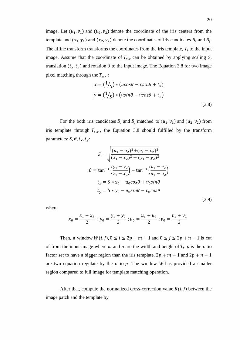
image. Let and denote the coordinate of the iris centers from the
template and and denote the coordinates of iris candidates and .
The affine transform transforms the coordinates from the iris template, to the input
image. Assume that the coordinate of can be obtained by applying scaling S,
translation and rotation to the input image. The Equation 3.8 for two image
pixel matching through the :
(3.8)
For the both iris candidates and matched to and from
iris template through , the Equation 3.8 should fulfilled by the transform
parameters: :
(3.9)
where
Then, a window and is cut
of from the input image where m and n are the width and height of . is the ratio
factor set to have a bigger region than the iris template. and
are two equation regulate by the ratio . The window W has provided a smaller
region compared to full image for template matching operation.
After that, compute the normalized cross-correction value between the
image patch and the template by

21
(3.10)
where
T denote the eye template
I denote the image patch
IT denote the pixel-by-pixel product of I and T
and are the average and standard deviation of the intensities of
pixels inside T and
is the average of the pixel by pixel product of I and T
Compute the cost of a pair of iris candidates and by the given equation
from the proposed algorithm
where
and are the costs computed by Equation 3.7
is the normalized cross-correlation value computed by using an eye
template and
t is a weight to adjust two terms of the cost (In the experiment, used t =0.5 for
all images)
3.4 Iris Tracking
Since the system is designed for higher level security purpose, so it provided an
option to allow the users to manually choose until the irises candidate is fall perfectly
in the region of user irises region. This option is provide when the users want higher
accuracy detection only because the irises candidate is affected in varying real time
environment sometime.
After getting the suitable iris candidate pair, it feedbacks to the system to
track the irises trajectory in the next frame. In the phase, Tracking-Leaning-Detection
(TLD) method proposed by Zdenek Kalal (2010) is implemented into the system.

22
TLD is a approach that closely integrates adaptive tracking with online learning of
object-specific detector. It will track the selected object starting from the first frame
by an adaptive tracker.
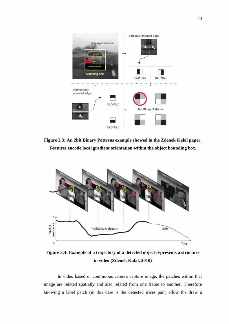
The object detector is based on the features call 2bit Binary Patterns (Zdenek
Kalal, 2010) because of their invariant to illumination and efficient multi-scale
implementation using integral images. These features measure gradient orientation
within a certain area, quantize it and output four possible codes. Figure 3.3 show an
illustration of this.
The posteriors Pr represent the initial parameter of the classifier and are
estimated incrementally throughout the learning process. The Pr are averaged and
classifier outputs positive response if the average is bigger than 50%. The detections
far from the target (in this case is the irises pair) represent the negative examples and
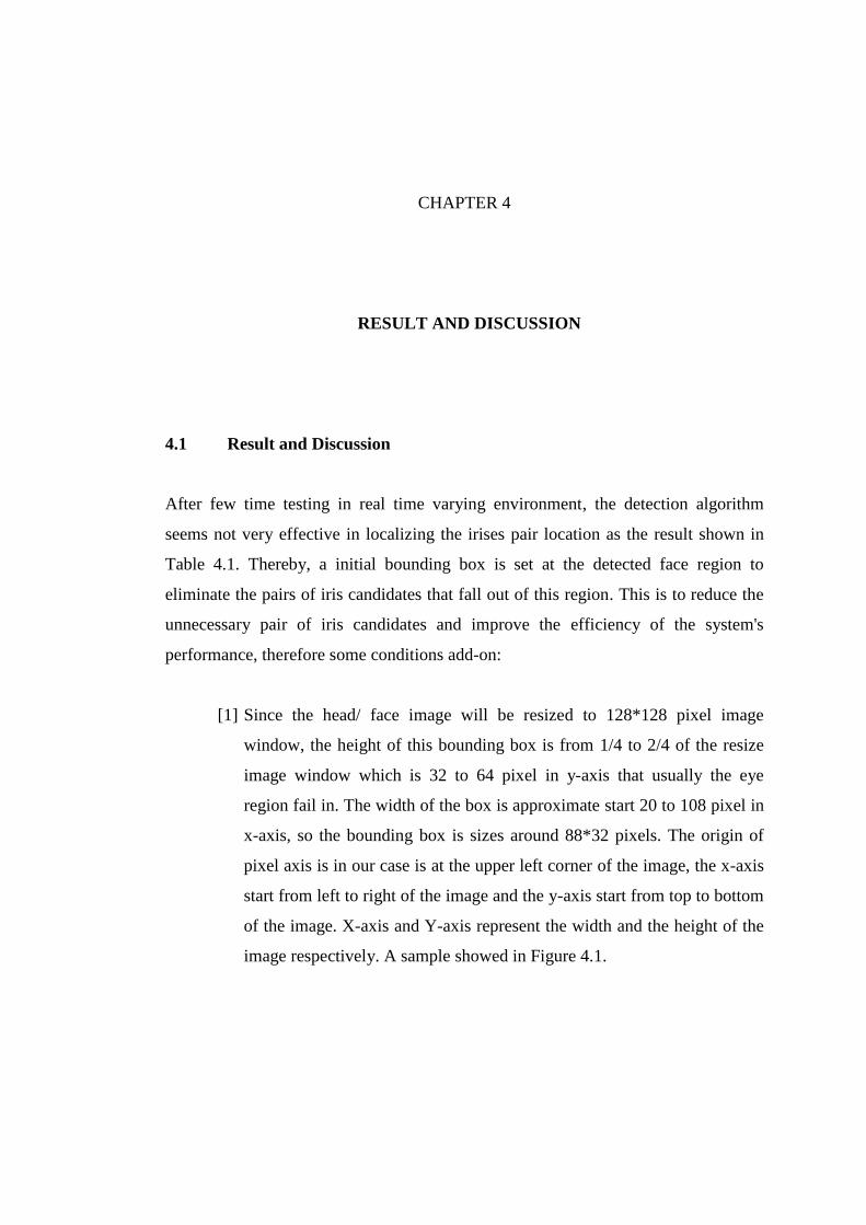
update the posteriors. In video based or continuous camera capture image, the
patches within that image are related spatially and also related from one frame to
another. Therefore knowing a label patch (in this case is the detected irises pair)
allow the draw a hypothesis about the labels of other patches. The constraints will be
used and the trajectory curve can be defined in the video or continuous capture image.
23
Figure 3.3: An 2bit Binary Patterns example showed in the Zdenek Kalal paper.
Features encode local gradient orientation within the object bounding box.
Figure 3.4: Example of a trajectory of a detected object represents a structure
in video (Zdenek Kalal, 2010)
In video based or continuous camera capture image, the patches within that
image are related spatially and also related from one frame to another. Therefore
knowing a label patch (in this case is the detected irises pair) allow the draw a

24
hypothesis about the labels of other patches. The constraints will be used and the
trajectory curve can be defined in the video or continuous capture image. An
example of an detected object trajectory is showed in Figure 3.4
Two processes (growing and pruning event) is observed the trajectory
robustly model the appearance and build an moving object detector. Both events
make errors, the stability of the system is achieved by their cancelation. The learnt
detector enables re-initialization of the tracker whenever previously observed
appearance reoccurs. Figure 3.5 illustrated this algorithm.
TLD show the real-time learning and classification is achievable with a
random forests classifier. This efficient classifier was used to represented the
decision boundary between the object and its background. After that, the learning
consists of building a validator that decides whether the object is patch corresponds
to the target or not.
Figure 3.5: The online model is initialized in the first frame by the manually
selected It is expanding by “growing events”, refined by “pruning events” and
slowly converges toward the unknown object manifold.
Although the TLD is strong enough to track the detected objects with online
training and learning, but it need a correct prior information to get the object
trajectory in next frames. So, the system is integrate the TLD with the previous

25
proposed detection algorithm to make the system more stable and intelligent in
automatically iris recognition system.
3.5 Summary
The methodology of the proposed system try to achieve the objective of recognizes
an unknown face and under the circumstances includes both eyes with various of
lighting source and background.
As a conclusion, this algorithm aims to detect the irises from input image in
real time. This algorithm will be use to test in few different database and some self-
captured image to find out the weakness. After that, improve the algorithm for iris
recognition and iris localization as well and implement it into real-time system.
CHAPTER 4
4 RESULT AND DISCUSSION
4.1 Result and Discussion
After few time testing in real time varying environment, the detection algorithm
seems not very effective in localizing the irises pair location as the result shown in
Table 4.1. Thereby, a initial bounding box is set at the detected face region to
eliminate the pairs of iris candidates that fall out of this region. This is to reduce the
unnecessary pair of iris candidates and improve the efficiency of the system's
performance, therefore some conditions add-on:
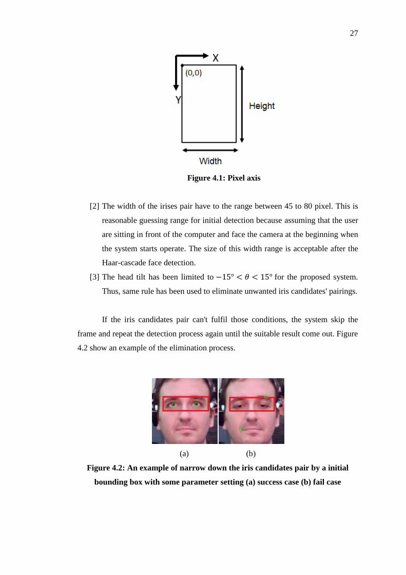
[1] Since the head/ face image will be resized to 128*128 pixel image
window, the height of this bounding box is from 1/4 to 2/4 of the resize
image window which is 32 to 64 pixel in y-axis that usually the eye
region fail in. The width of the box is approximate start 20 to 108 pixel in
x-axis, so the bounding box is sizes around 88*32 pixels. The origin of
pixel axis is in our case is at the upper left corner of the image, the x-axis
start from left to right of the image and the y-axis start from top to bottom
of the image. X-axis and Y-axis represent the width and the height of the
image respectively. A sample showed in Figure 4.1.
27
Figure 4.1: Pixel axis
[2] The width of the irises pair have to the range between 45 to 80 pixel. This is
reasonable guessing range for initial detection because assuming that the user
are sitting in front of the computer and face the camera at the beginning when
the system starts operate. The size of this width range is acceptable after the
Haar-cascade face detection.
[3] The head tilt has been limited to for the proposed system.
Thus, same rule has been used to eliminate unwanted iris candidates' pairings.
If the iris candidates pair can't fulfil those conditions, the system skip the
frame and repeat the detection process again until the suitable result come out. Figure
4.2 show an example of the elimination process.
(a) (b)
Figure 4.2: An example of narrow down the iris candidates pair by a initial
bounding box with some parameter setting (a) success case (b) fail case

28
By setting the initial checking, it has improves the accuracy of the iris
detection of the proposed algorithm. This is vital in providing accurate information
for the training later. In this experiment, the online AVI video datasets are used,
named Head Posed and Eye Gaze (HPEG) to test the system
This datasets are webcam videos displaying ranges of eye gaze and head pose
by 10 participants. They are recorded twice: the first time they slowly move their
head in various orientations relative to the camera. In the second set of recordings the
participants change their gaze from a frontal view to side view facing their right.
The first set of 10 recordings last 10 seconds each, the second set of 10
recordings last 12 seconds each. The same subjects appear in both experiments.
Ground truth for head pose is provided via a set of LEDs mounted on the user’s head.
Recordings are made at 30 frames per second, at a spatial resolution of 640 x 480
pixels. (S. Asteriadis, D. Soufleros, K. Karpouzis, S. Kollias, 2009).
The results of the iris detection on two videos are recorded in Table 4.1. In
this experiment, the results of the proposed algorithm before and after the
implementation of the bounding box with initial conditions are collected for analysis.
As shown in the Table 4.1, for Video Set 1 case, although the iris detected
frames have been scaled to 34.34% which is from 209 to 79 frames after assigning a
bounding box with initial conditions, but the success rate of the detected irises pairs
increase 43.92% (meanwhile failure detection rate is reduced to 43.92%) among the
detected frames. Some examples of the fail case that had been filter out like iris
candidates pair out of the frame or incorrect define are showed on Figure 4.3.
For Video Set 2, the iris detection rate is narrowed down to 42.42% which is
from 182 frames to 154 frames. The correct irises pairs detected among those 154
frames have increase 9.39% .It also reduce some incorrect and some fail cases like
the frame only have detect one iris.

29
Video Set 1*
Result Before
Bounding
After
Bounding
Discrepancy
Detected frame 209 79 -130
Frame Detection Rate 90.87%
(209/230)
34.34%
(79/230)
-56.53%
Irises pairs detection 59 57 -2
Success Rate 28.23%
(59/209)
72.15%
(57/79)
43.92%
Failure
rate
Only detect 1 iris 68 7 -61
Out of the frame 18 9 -9
Not Accuracy 64 5 -59
Fail Rate 71.77%
(150/209)
27.84%
(22/79)
-43.93%
Video Set 2**
Result Before
Bounding
After
Bounding
Discrepancy
Detected frame 182 154 -28
Frame Detection Rate 50.14%
(182/363)
42.42%
(154/363)
-7.72%
Irises pairs detection 107 105 -2
Success Rate 58.79%
(107/182)
68.18%
(105/154)
9.39%
Failure
rate
Only detect 1 iris 64 40 -24
Out of the frame 0 0 0
Incorrect 11 9 -2
Fail Rate 41.21%
(75/182)
31.82%
(49/154)
-9.39%
* Video Set 1 have total 230 frames.
** Video Set 1 have total 363 frames.
Table 4.1: Test Result of before and after add the initial bounding box of
Video Set 1 and 2
30
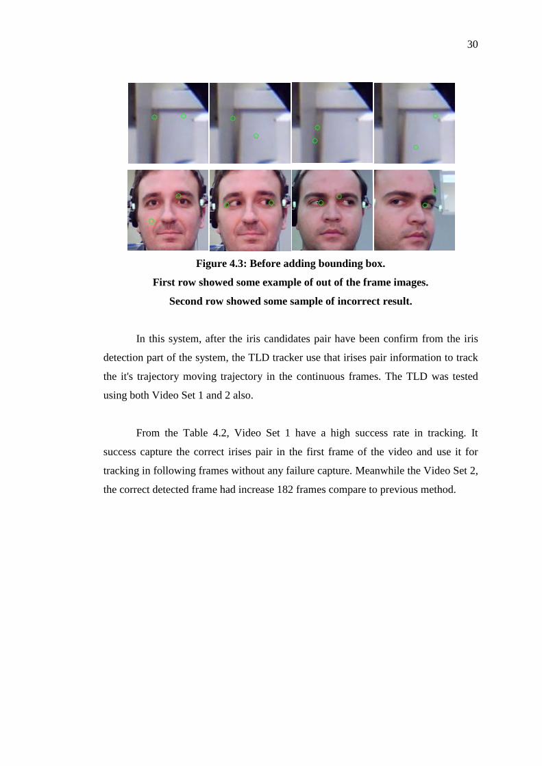
Figure 4.3: Before adding bounding box.
First row showed some example of out of the frame images.
Second row showed some sample of incorrect result.
In this system, after the iris candidates pair have been confirm from the iris
detection part of the system, the TLD tracker use that irises pair information to track
the it's trajectory moving trajectory in the continuous frames. The TLD was tested
using both Video Set 1 and 2 also.
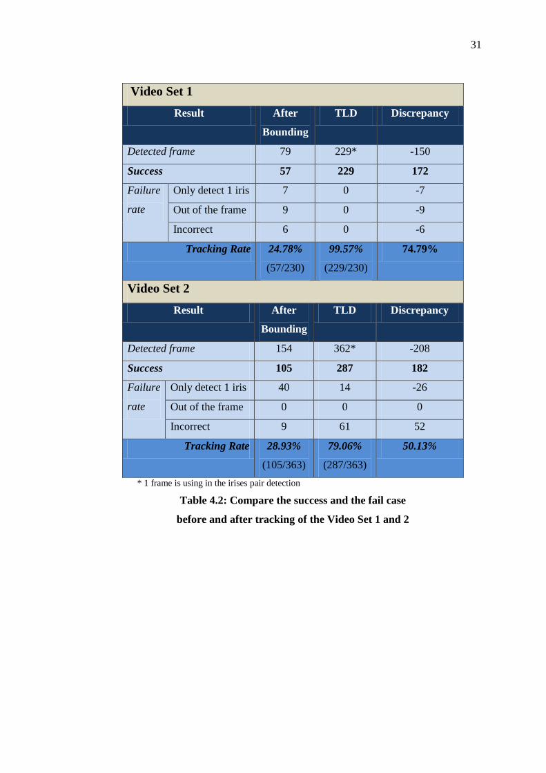
From the Table 4.2, Video Set 1 have a high success rate in tracking. It
success capture the correct irises pair in the first frame of the video and use it for
tracking in following frames without any failure capture. Meanwhile the Video Set 2,
the correct detected frame had increase 182 frames compare to previous method.
31
Video Set 1
Result After
Bounding
TLD Discrepancy
Detected frame 79 229* -150
Success 57 229 172
Failure
rate
Only detect 1 iris 7 0 -7
Out of the frame 9 0 -9
Incorrect 6 0 -6
Tracking Rate 24.78%
(57/230)
99.57%
(229/230)
74.79%
Video Set 2
Result After
Bounding
TLD Discrepancy
Detected frame 154 362* -208
Success 105 287 182
Failure
rate
Only detect 1 iris 40 14 -26
Out of the frame 0 0 0
Incorrect 9 61 52
Tracking Rate 28.93%
(105/363)
79.06%
(287/363)
50.13%
* 1 frame is using in the irises pair detection
Table 4.2: Compare the success and the fail case
before and after tracking of the Video Set 1 and 2
32
(a) (b)
(c) (d)
(e) (f)
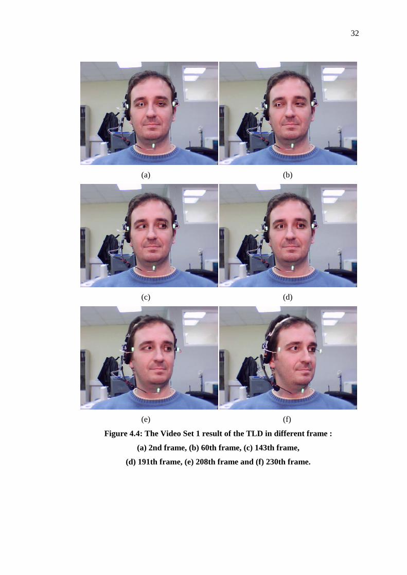
Figure 4.4: The Video Set 1 result of the TLD in different frame :
(a) 2nd frame, (b) 60th frame, (c) 143th frame,
(d) 191th frame, (e) 208th frame and (f) 230th frame.
33
(a) (b)
(c) (d)
(e) (f)
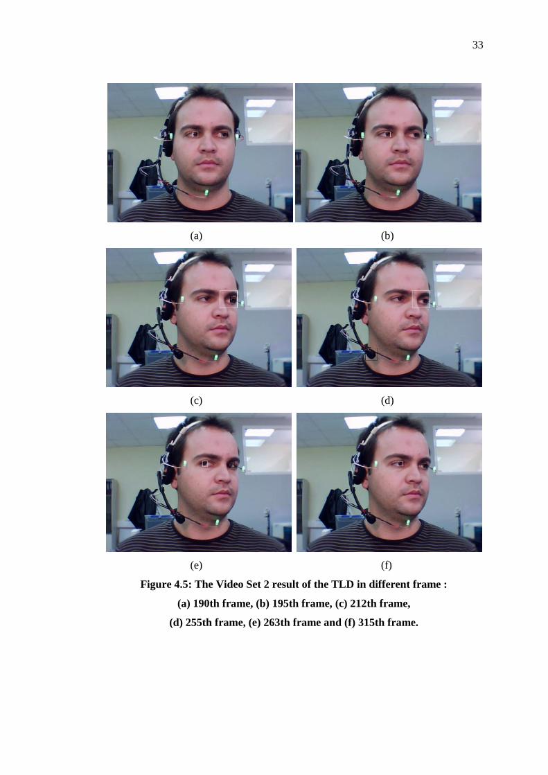
Figure 4.5: The Video Set 2 result of the TLD in different frame :
(a) 190th frame, (b) 195th frame, (c) 212th frame,
(d) 255th frame, (e) 263th frame and (f) 315th frame.
34
From the Figure 4.5, noted that the bounding box of right iris (black box)
starts to disappear from the 195th frames [Figure 4.5(b)] and appear back again but
overlapping with the white box at the 212th frames [Figure 4.5(c)]. The black box
starts tracking the microphone as an iris at the 255th frames. All box correctly track
back the both irises at 263th frame when the user faces his eye back to the front
(camera). The tracking is back to normal after that.
From result of Video Set 2, the system needs some time to generate the
positive examples for learning if the object has new movements. As showed in the
315th frames [Figure 4.5(f)], the system is able to track back because it learns from
the past.
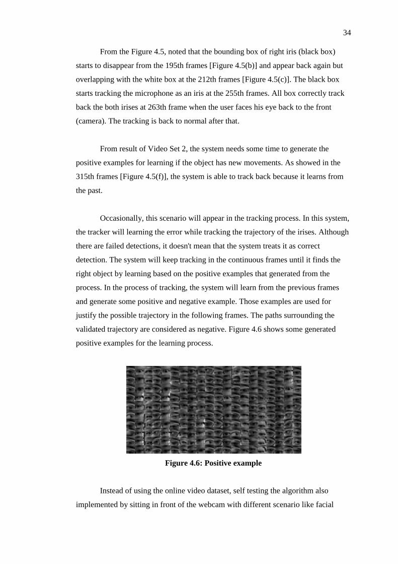
Occasionally, this scenario will appear in the tracking process. In this system,
the tracker will learning the error while tracking the trajectory of the irises. Although
there are failed detections, it doesn't mean that the system treats it as correct
detection. The system will keep tracking in the continuous frames until it finds the
right object by learning based on the positive examples that generated from the
process. In the process of tracking, the system will learn from the previous frames
and generate some positive and negative example. Those examples are used for
justify the possible trajectory in the following frames. The paths surrounding the
validated trajectory are considered as negative. Figure 4.6 shows some generated
positive examples for the learning process.
Figure 4.6: Positive example
Instead of using the online video dataset, self testing the algorithm also
implemented by sitting in front of the webcam with different scenario like facial

35
expression, head tilt, head rotation, with some obstacles occasionally, wearing with
or without spectacle, different distance from the camera and so on. In the following
figure, the output frames showed when the system is tested in real time. In Figure
4.7, the user tries to cover the face using some obstacle their hand, the left and right
iris are still detected correctly right after removing his hand. The result shows that
the system has quite response to obstacles.
Figure 4.7: The tracking result when the user face have some obstacle
(without spectacle)
36
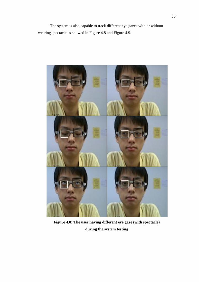
The system is also capable to track different eye gazes with or without
wearing spectacle as showed in Figure 4.8 and Figure 4.9.
Figure 4.8: The user having different eye gaze (with spectacle)
during the system testing

37
Figure 4.9: The user showing different eye gaze (without spectacle)
during the system testing

38
Changing the position of the head and viewing direction also wouldn't affect
the stability of the system. As showed in Figure 4.10, the user tilts his head/ viewing
up and down during the system testing. The tracking box is still remains in frames.
Figure 4.10: The user looking up and down during the system testing
39
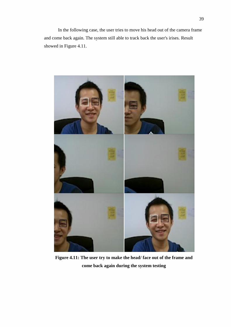
In the following case, the user tries to move his head out of the camera frame
and come back again. The system still able to track back the user's irises. Result
showed in Figure 4.11.
Figure 4.11: The user try to make the head/ face out of the frame and
come back again during the system testing
40
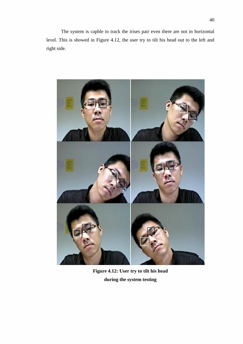
The system is capble to track the irises pair even there are not in horizontal
level. This is showed in Figure 4.12, the user try to tilt his head out to the left and
right side.
Figure 4.12: User try to tilt his head
during the system testing

41
The system is able to learn the initial user's face even the user is out of the
frame and replace by other user. Figure 4.13 showed the result.
Figure 4.13: Another user try to capture his face
when another is leaving during the system testing
42
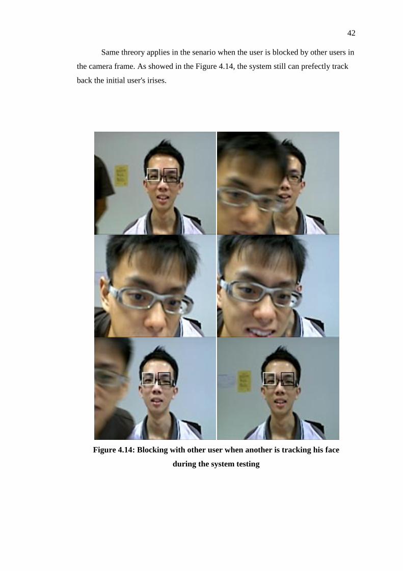
Same threory applies in the senario when the user is blocked by other users in
the camera frame. As showed in the Figure 4.14, the system still can prefectly track
back the initial user's irises.
Figure 4.14: Blocking with other user when another is tracking his face
during the system testing
43
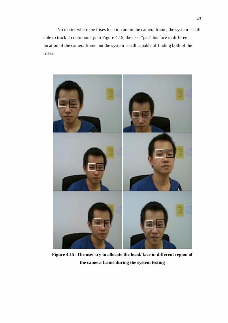
No matter where the irises location are in the camera frame, the system is still
able to track it continuously. In Figure 4.15, the user "pan" his face in different
location of the camera frame but the system is still capable of finding both of the
irises.
Figure 4.15: The user try to allocate the head/ face in different region of
the camera frame during the system testing
44
In the testing process, found that the processing speed is slowing down
because two object (right iris and left iris) is tracking in the same time. So, the
system is try to test by tracking the only one iris (in this case is right iris) using self-
capture video dataset (called Video Set 3 after). The result show that the system run
more faster compare when tracking two irises in the same time. Figure 4.16 showed
that the testing result:
Image (a) showed the result of 10th frame in both irises tracking,
Image (b) showed the result of 10th frame in right iris tracking;
Image (c) showed the result of 70th frame in both irises tracking,
Image (d) showed the result of 70th frame in right iris tracking.
Image (e) showed the result of 150th frame in both irises tracking,
Image (f) showed the result of 150th frame in right iris tracking.
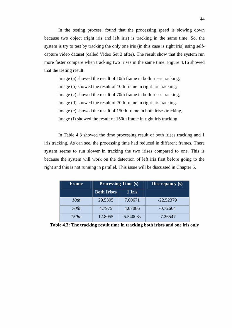
In Table 4.3 showed the time processing result of both irises tracking and 1
iris tracking. As can see, the processing time had reduced in different frames. There
system seems to run slower in tracking the two irises compared to one. This is
because the system will work on the detection of left iris first before going to the
right and this is not running in parallel. This issue will be discussed in Chapter 6.
Frame Processing Time (s) Discrepancy (s)
Both Irises 1 Iris
10th 29.5305 7.00671 -22.52379
70th 4.7975 4.07086 -0.72664
150th 12.8055 5.54003s -7.26547
Table 4.3: The tracking result time in tracking both irises and one iris only

45
(a) (b)
(c) (d)
(e) (f)
Figure 4.16: The result frame in tracking both irises and one iris only testing
46
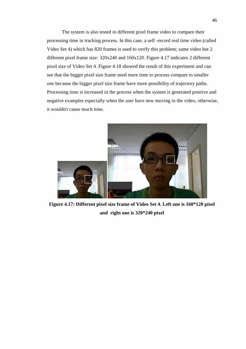
The system is also tested in different pixel frame video to compare their
processing time in tracking process. In this case, a self -record real time video (called
Video Set 4) which has 820 frames is used to verify this problem; same video but 2
different pixel frame size: 320x240 and 160x120. Figure 4.17 indicates 2 different
pixel size of Video Set 4. Figure 4.18 showed the result of this experiment and can
see that the bigger pixel size frame need more time to process compare to smaller
one because the bigger pixel size frame have more possibility of trajectory paths.
Processing time is increased in the process when the system is generated positive and
negative examples especially when the user have new moving in the video, otherwise,
it wouldn't cause much time.
Figure 4.17: Different pixel size frame of Video Set 4. Left one is 160*120 pixel
and right one is 320*240 pixel

Figure 4.18: Time against the frame graph of tracking among 820 frames of Video Set 4 in 320x240 and 160x120 pixel size.
0
5
10
15
20
25
30
35
40
12
14
16
18
11
01
12
11
41
16
11
81
20
12
21
24
12
61
28
13
01
32
13
41
36
13
81
40
14
21
44
14
61
48
15
01
52
15
41
56
15
81
60
16
21
64
16
61
68
17
01
72
17
41
76
17
81
80
1
Tim
e (s
)
Frame
Video Set 4
160 x 120 pixels
320 x 240 pixels
48
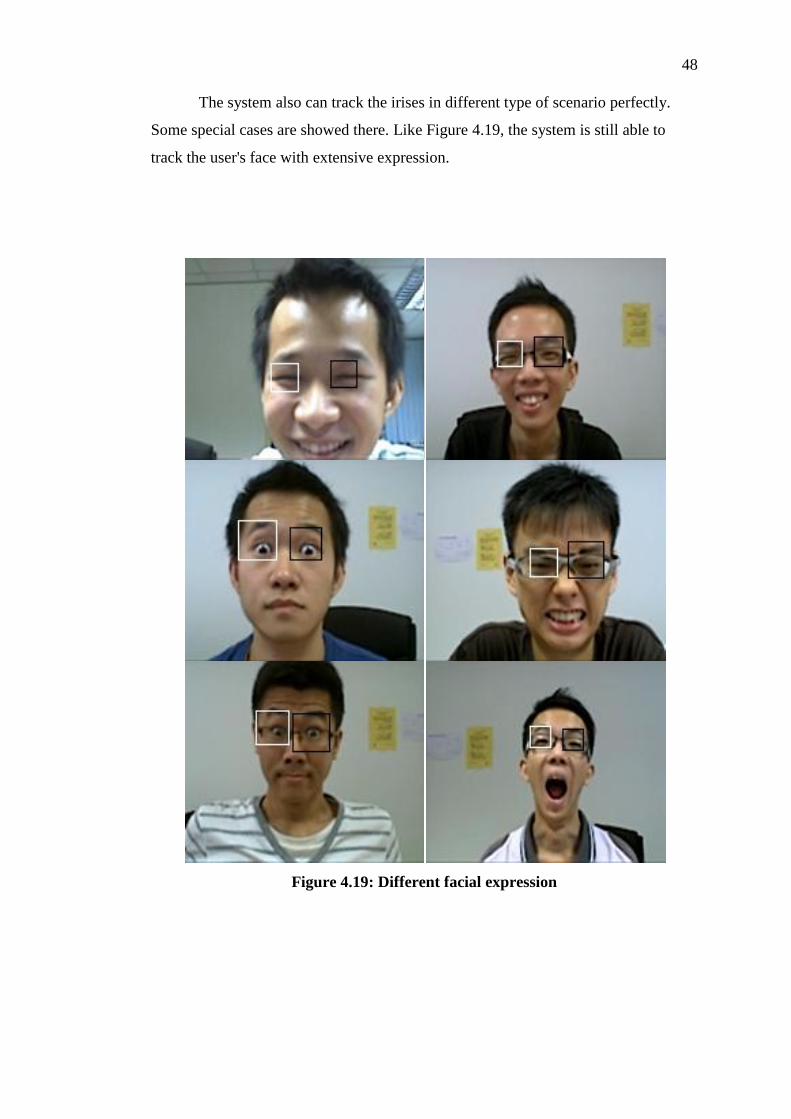
The system also can track the irises in different type of scenario perfectly.
Some special cases are showed there. Like Figure 4.19, the system is still able to
track the user's face with extensive expression.
Figure 4.19: Different facial expression
49
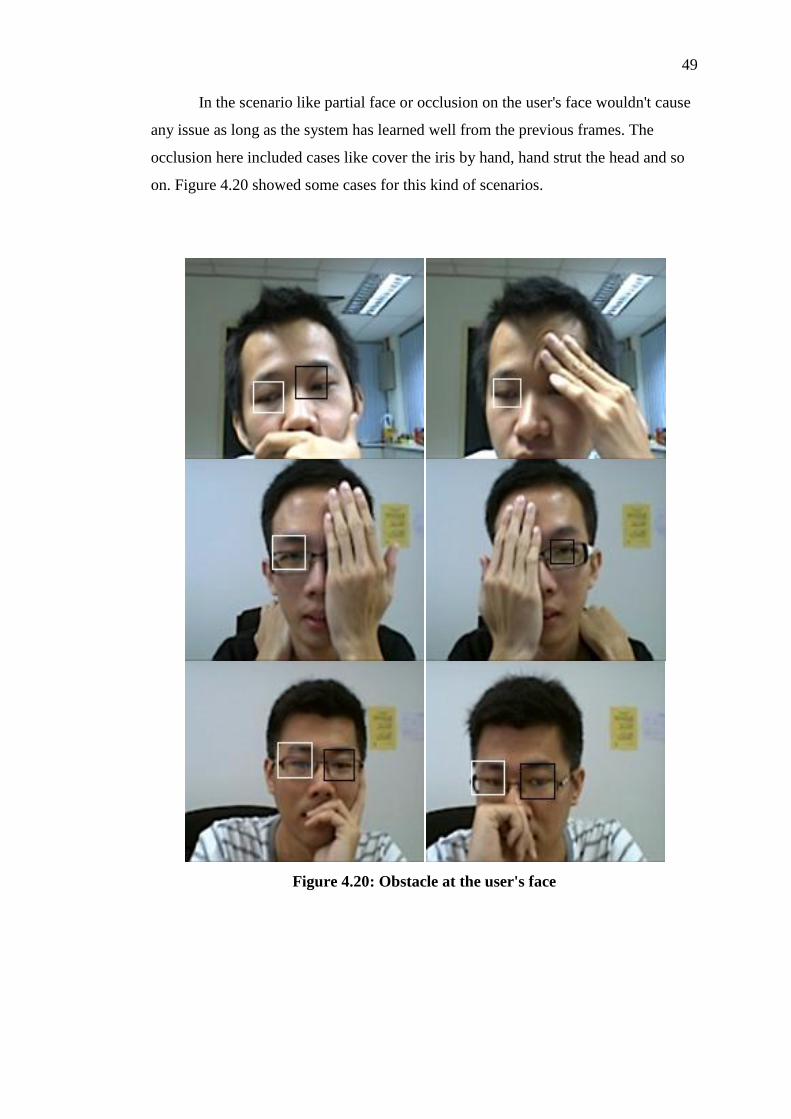
In the scenario like partial face or occlusion on the user's face wouldn't cause
any issue as long as the system has learned well from the previous frames. The
occlusion here included cases like cover the iris by hand, hand strut the head and so
on. Figure 4.20 showed some cases for this kind of scenarios.
Figure 4.20: Obstacle at the user's face
50
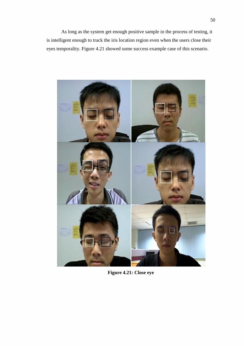
As long as the system get enough positive sample in the process of testing, it
is intelligent enough to track the iris location region even when the users close their
eyes temporality. Figure 4.21 showed some success example case of this scenario.
Figure 4.21: Close eye

51
Of course, in the process of tracking some failure detection are reported. The
following images in Figure 4.22 shows some failed cases.
Figure 4.22: Fail case samples
From those images, can know that the miss detect can be occurred in any time
and doesn't have any fix pattern. This is because when the tracker fail in finding the
correct iris/ irises. it will track other high similarity moving objects in the frames.
Although the system will miss detect the object, it doesn't mean the system identified
it as correct detection but just assuming it. Once the system verify it is not the correct
object as pre-defined (irises pair) by learning form the positive examples generated
in the process, it will always go back to the initial detected location as long as the

52
default detection of irises is correct. This might happen when the system doesn't have
enough positive examples to learn and improve. As the positive example increases in
the process, the system will become more stable and robust. It also affected by the
size of the defined iris box (white box and black box) in getting enough information
for the learning curve within a short time.

CHAPTER 5
5 CONCLUSION
5.1 Conclusion
In this project, an effective algorithm is proposed for real time automatically iris
recognition. The tracker start the tracking based on a initial information from a
correct detected irises. In the tracking process, the success rate depends on the
number of positive example need in the learning in the tracking process. The system
is more stable and robust if more positive examples is generated. This is because the
system needs to verify the trajectory whether is correct or not by using the positive
examples.
More training and learning, more accuracy and robust the system performs.
As the Video Set 2 results showed, the system need time to learn the user's new
moving and it able to track the correct irises pair again if the user do that particular
action again. In this process, the system generates the positive examples for system
to learn and generate negative examples to avoid the nearly incorrect trajectory.
Through many time of testing, the system runs slower in higher resolution
images. This will affect the real time performance because the system can't capture
every frame and this will cause the learning rate became low. Since the system run
faster when tracking 1 iris nicely, it also can use for some

CHAPTER 6
6 RECOMMENDATIONS AND FUTURE IMPROVEMENTS
6.1 Recommendations and Future Improvements
In the process of using online profession video dataset and self-produced video set,
found out that the user with wearing spectacle/ glass have a quite hard time to detect
the iris compare to whose didn't. The reason of that is vary, some is due to the strong
reflection of the surrounding lighting on the glass, and some is because the edge of
the spectacle is blocking the iris or appeal at the same line as the irises horizontally.
It also might be the shape/frame of the spectacle because the head/ face detection fail
at first. Besides that, the low transparency spectacle will also affects the visibility of
iris. Sometime the facial expressions of the users have caused the eyes to be nearly or
indirectly closed causing the irises not visible enough for detection also. So the
system can detect the user irises more faster for those who didn't wear spectacle.
Although for those who wearing spectacle have a hard time to detect their irises at
the initial, but once the system capture their irises and generates some positive
examples, the system is can learn for the positive example and able to track the irises
well after that. But sometime it also have some rare success case happened at the
initialize of the tracking. Some examples are showed in Figure 6.1.

55
Figure 6.1: User who wearing spectacle have hard time to detect the irises.
First row showed some example of deflect irises pair result.
Second row showed some sample of accuracy result that happen rarely at the
initial tracking.
There are some researchers working on the removal of glasses from the input
images. Wu, Chenyu et al. (2004) have created a system can automatically remove
eyeglasses from an input face image by apply Morkov chain Monte Carlo method.
Cheng Du and Guangda Su (2005) have also proposed a method by synthesize a
natural looking eyeglassless facial image by recursive error compensation of PCA
reconstruction. All of those methods can be study further more to improve this
system.
On the other hands, the system runs very slow in the process of compilation.
To overcome this problem, we suggest implementing CUDA (www.nvidia.com.) for
parallel computer processing. CUDA (Compute Unified Device Architecture) is a
technology by nVidia allowing programmers to write code that can be uploaded and
executed in recent nVidia graphics cards, exploiting their massively parallel
architecture in order to obtain a relevant reduction of computer time. C++ developers
can write particular functions called "kernels" that can be called from the host and
executed on CUDA device simultaneously by many threads in parallel.
56
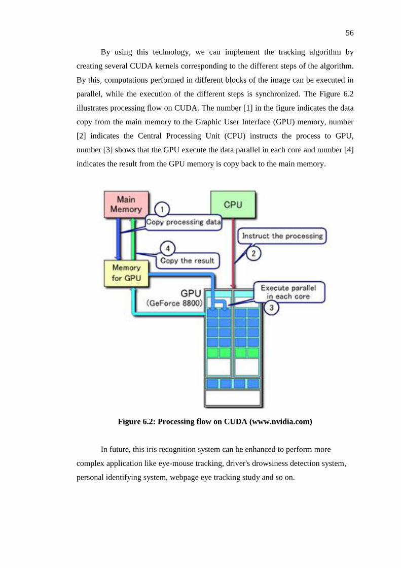
By using this technology, we can implement the tracking algorithm by
creating several CUDA kernels corresponding to the different steps of the algorithm.
By this, computations performed in different blocks of the image can be executed in
parallel, while the execution of the different steps is synchronized. The Figure 6.2
illustrates processing flow on CUDA. The number [1] in the figure indicates the data
copy from the main memory to the Graphic User Interface (GPU) memory, number
[2] indicates the Central Processing Unit (CPU) instructs the process to GPU,
number [3] shows that the GPU execute the data parallel in each core and number [4]
indicates the result from the GPU memory is copy back to the main memory.
Figure 6.2: Processing flow on CUDA (www.nvidia.com)
In future, this iris recognition system can be enhanced to perform more
complex application like eye-mouse tracking, driver's drowsiness detection system,
personal identifying system, webpage eye tracking study and so on.
57
Further step to reduce the false positives produced by iris recognition system
is necessary. Artificial Intelligence algorithms, like fuzzy logic can be added into the
system to adjust the initial condition of the bounding box for different individual.
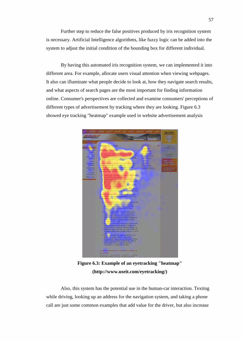
By having this automated iris recognition system, we can implemented it into
different area. For example, allocate users visual attention when viewing webpages.
It also can illuminate what people decide to look at, how they navigate search results,
and what aspects of search pages are the most important for finding information
online. Consumer's perspectives are collected and examine consumers' perceptions of
different types of advertisement by tracking where they are looking. Figure 6.3
showed eye tracking "heatmap" example used in website advertisement analysis
Figure 6.3: Example of an eyetracking "heatmap"
(http://www.useit.com/eyetracking/)
Also, this system has the potential use in the human-car interaction. Texting
while driving, looking up an address for the navigation system, and taking a phone
call are just some common examples that add value for the driver, but also increase

58
the risk of driving. By implement this system, it can tracking the driver's eye or irises
and the user can their gazes, eye blink or head movement and translate them into
commands to control other interface instead of using their hands. It also can be a
methods for predicting driver distraction with in-car devices.

REFERENCES
Ba Linh NGUYEN (2009). Eye Gaze Tracking; IEEE vol. 2,2009.
B. Kim, S.C. Kee, and J.Y. Kim. (2005). Fast Detection of Multi-View Face and Eye
Based on Cascaded Classifier. Proc. of IAPR Conf. on MVA. C. A. .
Perez, V. A. Lazcano, and P. A. Est´ evez (2007) Real-time irisdetection on coronal-
axis-rotated faces, IEEE Trans. on Systems,Man, and Cybernetics, Part C, vol. 37,
no. 5, pp. 971–978, 2007.
Chai Tong Yuen, Mohamed Rizon and Muhammad Shazri. (2009) Real-Time
Detection of Face and Iris. WSEAS Journal Transactions on Signal Processing
(ISSN: 1790-5052).
Chai Tong Yuen , M. Rizon , Woo San San and M. Sugisaka (2008) Automatic
detection of face and facial features. Proceedings of the 7th WSEAS International
Conference on Signal Processing, Robotics and Automation. p.230-234.
Cambridge, UK.
C.H. Lin, J.L. Wu. (1999). Automatic facial feature extraction by genetic algorithms,
IEEE Trans. Image Process. 8 (6) 834–845.
D. Hansen, Q.Ji (2010). In the Eye of the Beholder: A Survey of Models for Eyes
and Gaze", Pattern Analysis and Machine Intelligence, IEEE Transactions on
March 2010
D.J. Beymer. (1994). Face recognition under varying pose. Proceedings of the IEEE
Conference on Computer Vision and Pattern Recognition. pp. 756–761. Seattle,
Washington.
El-Bakry and H.M (2001). Human Iris Detection Using Fast Cooperative Modular
Neural Nets. Neural Networks, Proceedings of International Joint Conference on
IJCNN '01, vol.1, pp 577 –582..
Freund Y, Schapire RE (1995). A decision-theoretic generalization on on-line
learning and an application to boosting. In: Proceedings of the 2nd European
Conference on Computational Learning Theory (Eurocolt95); Barcelona,
Spain;1995 p. 23–37; J Comput Syst Sci 1997 ; 55(1):119–139.

60
G. Xu, Y. Wang, J. Li and X. Zhou (2009). Real time detection of eye corners and
iris center from images acquired by usual camera, In Proc. IEEE 2nd Int. Conf.
Intelligent Networks and Intelligent Systems, pp.401-404, 2009.
H. Grabner and H. Bischof (2006).. On-line boosting and vision. In Proceedings
IEEE Conference on Computer Vision and Pattern Recognition (CVPR), volume 1,
pages 260-267,2006
Huang Y. P., Luo S. W. and Chen E. Y. (2002). An Efficient Iris Recognition System
International Conference on Machine Learning and Cybernetics, Vol.1: 450-454,
Beijing, China.
Jakob Nielsen (2009). Eyetracking Research Retrieved April 17, 2012 from
http://www.useit.com/eyetracking/.
J. G. Daugman. (1993). High Confidence Visual Recognition of Persons by a Test of
Statistical Independence. IEEE Trans.Pattern Analysis and Machine Intelligence..
15(11).1148-1161.
John Daugman (1997). Neural Image Processing Strategies Applied in Real-Time
Pattern Recognition. Real-Time Imaging, 3(3): pp 157-171.
J. Yang and A. Waibel. (1996). A Real time Face Tracker. Proc. of the Third IEEE
Workshop on Applications of Computer Vision, pp. 142-147. Sarasota, Florida.
K. Fukui and O. Yamaguchi. (1997). Facial feature point extraction method based on
combination of shape extraction and pattern matching. Trans. IEICE Japan J80-
D-II (8) 2170–2177.
Kronfeld. (1962). Gross Anatomy and Embryology of the Eye. The Eye, Academic
Press. London.
L.Flom, A. Safir. (1987). Iris Recognition System. U. S. Patent, No.4641394..
L. G. Kourkoutis, K. I. Panoulas, and L. J. Hadjileontiadis (2007) Automated iris and
gaze detection using chrominance: application to human-computer interaction
using a low resolution webcam, Proc. of 19th IEEE International Conference on
Tools with Artificial Intelligence (ICTAI-2007) October 29-31, 2007, Patras,
Greece, vol. 1, pp. 536-539.
M.R.R. Fini, M.A.A. Kashani, and M. Rahmati (2011). Eye detection and tracking in
image with complex background, Electronics Computer Technology (ICECT),
2011 3rd International Conference on, vol.6, pp.57-61, 8-10 April 2011.
M. Turk and A. Pentland. (1991)., Eigenfaces for recognition. J. Cognitive Neurosci.
3 (1) 71–86.

61
Nicolas Schneider, Peter J. Bex, Erhardt Barth, Michael Dorr (2011). An open-
source low-cost eye-tracking system for portable real-time and offline tracking,
NGCA 2011: 8
OpenCV Reference Manual. (2010). Retrieved March 18, 2010 from
https://code.ros.org/trac/opencv/export/2866/trunk/opencv/doc/opencv.pdf.
P.Viola and M.Jones (2001). Robust Real-time Object Detection. Proc. of IEEE Int'l
Conf. on Computer Vision 2001 Workshop on Statistical and Computation
Theories of Vision. .
R. Brunelli, T. Poggi. (1993). Face recognition: features versus templates. IEEE
Trans. Pattern Anal. Mach. Intell. 15 (10) 1042–1052.
Rupal Khilari. (2010). Iris Tracking and Blink Detection for Human-Computer
Interaction using a Low Resolution Webcam, ICVGIP 2010. Chennai, India.
S.R. Sternberg. (1986). Grayscale morphology. Comput. Vision Graphics Image
Process. 35, 333–355.
S. Spors and R. Rabenstein (2001), A real time face tracker for colour video, Proc. of
IEEE Int. Conf. on Acoustics, Speech & signal Processing (ICASSP), vol. 3, Utah,
USA, 7-11 May 2001, pp. 1493-1496.
Tsuyoshi Kawaguchi and Mohamed Rizon. (2003). Iris detection using intensity and
edge information. Pattern Recognition: 549~562.
Tsuyoshi Kawaguchi, Daisuke Hidaka and Mohamed Rizon. (2000). Detection of
Eyes from Human Faces by Hough Transform and Separability Filter. ICIP'2000.
V. Kruger, A. Happe, and G. Sommer (1999). Affine real-time face tracking using a
wavelet network, Proc. of IEEE Int. Workshop on Recognition, Analysis, and
Tracking of Faces and Gestures in Real-Time Systems, 26-27 Sep. 1999, pp. 141-
148.
What is CUDA? (n.d.) Retrieved April 17, 2012, from
http://www.nvidia.com/object/cuda_home_new.html
Y. Freund and R. Schapire. (1996). Experiments with a new boosting algorithm.
Proc.of Int'l Conf. on Machine Learning, pp. 148-156.
Yoav Freund and Robert E. Schapire. (1997). A decision-theoretic generalization of
on-line learning and an application to boosting. Journal of Computer and System
Sciences, 55(1):119–139.

62
Y. Tian, T. Kanade and J.F. Cohn. (2000). Recognizing upper face action units for
facial expression analysis. Proceedings of the IEEE Conference on Computer
Vision and Pattern Recognition. Vol. 1,pp. 294–301. Hilton Head Island, South
Carolina.
Z. Kalal, K. Mikolajczyk, and J. Matas (2010), Face-TLD: Tracking-Learning-
Detection Applied to Faces, International Conference on Image Processing, 2010.
Zdenek Kalal, Krystian Mikolajczyk, Jiri Matas (2010) Forward-Backward Error:
Automatic Detection of Tracking Failures, ICPR 2010: 2756-2759
Zdenek Kalal, Jiri Matas, Krystian Mikolajczyk (2010), P-N learning: Bootstrapping
binary classifiers by structural constraints, CVPR 2010: 49-56
Z. Zhu, T. Morimoto, H. Adachi, O. Kiriyama, T. Koide, and H. J. Mattausch (2005).
Multi-view Face Detection and Recognition using Haar-like Features. Research
Center for nano-devices and systems, Hiroshima University

63