real time image processing using fpga devices -...
TRANSCRIPT

Real Time Image ProcessingReal Time Image Processing
using FPGA devicesusing FPGA devices
Professor Michel PAINDAVOINEUniversité de Bourgogne
Aile des Sciences de l ’IngenieurBP 400 - 21011 DIJON Cedex - France
email:[email protected]

I- Objectives of the Real Time Image Processing II- Algorithm To Architecture Methodology
III- Digital filters applied to Image Processing
IV- Signal and Image Processing Algorithms Optimization
V- FPGA Implementation of Real Time Image Processing Algorithms using VHDL
OUTLINEOUTLINE

OBJECTIVESOBJECTIVES
* Computation Time Limitation in the goal to obtain * Computation Time Limitation in the goal to obtain Real-Time:Real-Time:Examples:- Edge Detection using the Canny-Deriche Algorithm corresponds to 12 additions and 12 multiplications per pixel in less than 100ns (Pixel frequency=10MHz)
- Face Recognition using Neural Networks : Image of 200x200 pixels corresponds to 40K inputs for the Neural Network and it needs to process a 40Kx40K matrix in less than 40ms (25 images per second)

* Computer Size Limitation :* Computer Size Limitation :
Example:
- High Speed Images:
500 images per second, each image=1024x1024 pixels
corresponds to a 500 Mpixels per second and needs large memories .
Real Time Image Processing needs Algorithm to Architecture Methodology

Example: Real Time Imaging System
Applied to Human Movement Analysis
FAST CAMERA 500 IMAGES/S
CMOS Image Sensor from MICRON
Embedded Image processing inside FPGA
IMAGE Format: 1280x1024
USB2

Fast Smart Camera Architecture
FPGA(Xilinx)
Virtex-IIXC2V3000
(3,000 gates)
CMOS sensor(Micron)
MTM9M413
1,3 MPixels
USB2Interface
EEPROM(Prg FPGA)
SRAM Memory(512 Mbytes)
FPGA:-Sensor and interfaces control-Embedded Real Time Image Processing
Memory: SRAM: stores temporary data
during processing

Connectors: SCSIPower supplyUSB2VideoJTAG and Camera control
Camera back-face:
CMOS sensor board FPGA board
Interface board
Internal Camera view:

Real Time Calculation Component: FPGA
Storage of the parameters for the target detection,Target detection in real time, Target position transmission using USB2 interface.

PARAMETERS OF DETECTION: •GREY LEVEL THRESHOLD•MINIMUM LENGTH OF THE TARGET•MAXIMUM LENGTH OF THE TARGET
MINIMAXI
Targets Detection Principle

DETECTION VISUALIZATION

Tracking Application in Real Time (300 Images/sec)

Results for this implementation Real Time Movement Analysis working at 500 Images per second (Image Format: 1024x1280 pixels)
Using Programmable Component (FPGA)
Applications: Human Movement Analysis like Sport,
Reeducative Medicine, Ergonomic Interfaces Design,
Cinema,…
In order to increase performances it’s necessary to study other solutions:
Using of Algorithm to Architecture Methodology
I- Objectives of the Real Time Image Processing II- Algorithm To Architecture Methodology
III- Digital filters applied to Image Processing
IV- Signal and Image Processing Algorithms Optimization
V- FPGA Implementation of Real Time Image Processing Algorithms using VHDL
OUTLINEOUTLINE

◊ Choice and Test of the algorithm using a standard computer◊ Comparison of different specific architectures (using CAD tools) ◊ Algorithm modification◊ Architecture validation◊ End modification of the architecture
II- Algorithm To Architecture II- Algorithm To Architecture Methodology DescriptionMethodology Description
(Results research from French GDR-CNRS ISIS)(Results research from French GDR-CNRS ISIS)[http://gdr-isis.org][http://gdr-isis.org]

Image Processing Image Processing Algorithms ClassificationAlgorithms Classification
LOW LEVELPROCESSING
- Filtering- Segmentation- FFT, ...
MEDIUM LEVELPROCESSING
- Coding- Compression
HIGH LEVELPROCESSING
- Classification- Pattern Recognition- Measurements
Decision
Image Image List

Source: Michel Robert
New Architectures:New Architectures: from the first Integrated Circuit in 1960 to … from the first Integrated Circuit in 1960 to …
Complex Architectures in 2010!Complex Architectures in 2010!

Moore law: from the sixties each 18 months, the number of transistors is multiplied by 2

Memories less and less expensives:

De nouvelles architectures doivent être développées... !
Cellular telUMTS
Multimedia
Cellular phoneRadiocom 2000
Cellular telGSM
ANAL
OG
DIG
ITAL
70 80 90 00 10
# tr
ansi
stor
s (lo
g) 1G 2G
Processor/DSP
memory GAP
Algorithms Complexity
3G
Challenges for development of new architectures:Algorithms are more and more complex
year

From now to … 2010
Source: Michel Robert

AAA Methodology
Algorithm
Matlab,C++
DataFlow
ASIC
FPGA
DSP
Processor
Set of Components
Task Task
TaskTask
Task
Timing specificationTask repartitionCode Generation
SynDex
Algorithm adaptation
Architecture
Achitecture adaptation

I- Objectives of the Real Time Image Processing II- Algorithm To Architecture Methodology
III- Digital filters applied to Image Processing
IV- Signal and Image Processing Algorithms Optimization
V- FPGA Implementation of Real Time Image Processing Algorithms using VHDL
OUTLINEOUTLINE

III-1 Digital filtering operation
h(n)*x(n)y(n) =
x(n) h(n) y(n)
)z(H).z(X)z(Y =
withJ
J1
10
II
110
zb...zbbza...zaa)z(H −−
−−
++++++=
)(...)()(...)()()(0
1
0
1
0
1
0
1
0
0 zYzbbzYz
bbzXz
bazXz
bazX
bazY JJII −−−− −−−+++=
)(...)1()(...)1()()(00
1
00
1
0
0 Jnybbny
bbInx
banx
banx
bany JI −−−−−−++−+=
Z

Implementation using Matlab:
);x,B,A(filtery];b....bb[B];a....aa[A
J10
I10
=>>=>>=>>
Synoptic Schematics:
1z− 1z− 1z−
x x x x
+ + +
….
…..
0
0ba
0b1a
0
2ba
0
Iba
X(z)
+
1z−
1z−+
+
x
x 0b1b
0
Jbb
Y(z)

III-2 Image Edge Detection with Sobel digital filter
-1 0 1-2 0 2-1 0 1
-1 -2 -1 0 0 0 1 2 1
h1=
h2=
x
yf(x,y)
2h*)y,x(f1h*)y,x(f)y,x(g +=
}{}{ )2y,2x(f)2y,1x(f2)2y,x(f
)y,2x(f)y,1x(f2)y,x(f)y,x(1g2h*)y,x(f)y,x(2get1h*)y,x(f)y,x(1g
−−+−−+−−−+−+=
==

[ ]
[ ] [ ] [ ] [ ]11N211
21N221
z1.z1)z(Fzz1.z1)z(F)z(1G
)z(Fz)z(Fz2)z(Fz)z(Fz)z(Fz2)z(F)z(1G
−−−−−
−−−−−
++−++=
++−++=
With N : Number of Pixels per line
N2z−
1z−
+
1z−
+
1z−
+
1z−
+
-
+
F(z)
F(z)
G1(z)
G2(z)
G(z)

F(z)
N2z−
1z−
+
1z−
+
1z−
+
1z−
+
-G1(z)
f(x,y)D Q
D Q
D QD Q
Fifo (2N)
g1(x,y)
Abs[g1(x,y)]
clk
clkclk
clk
clk
Clk= Pixel Clock

g1(x,y)
Abs[g1(x,y)]
a1(x,y)
b1(x,y)
Absolute value calculation:
g1(x,y)1 - g1(x,y)
Mux 2 to 1
a1(x,y)
b1(x,y)
a1, b1, g1 and (-g1) on 8 bitsSign on 1bitAbs[g1] on 8 bits
Abs[g1(x,y)]
Sign

Original Image with High Signal to Noise Ratio (SNR)
Original Image Edge detection with Sobel Digital Filter

Countours are lost in the noise!
Original Image with Low Signal to Noise Ratio (SNR)
Edge detection with Sobel Digital FilterOriginal Image

III-3 Edge detection using optimal filters:
CANNY-DERICHE, SHEN-CASTAN, …
CANNY-DERICHE is based on 3 criteria:
- SNR increasing
-Multiple responses elimination
- Best location

Generalized Canny-Deriche filter description:
02
)(
02
1)(
xpourexC
et
xpourexC
sx
sx
=
≥−=−
Image model:

Using of 2 filters: Derivative filter and Smoothing filter
If with consider the 3 Canny-Deriche criteria, we obtain for the horizontal direction 4 digital IIR filters:
Z transform Derivative filter:
)0(3
52
431
221)(
)0(3
52
41
31
22
11)(
xzazaza
zazazd
xzazaza
zazazd
−+−
+=−
≥−−−+−−
−+−=+
Z transform Smoothing filter:
)0(1
)(
)0(1
)(
33
221
221
33
22
11
22
11
xzdzdzd
zczczl
xzdzdzd
zczczl
−−
−−−
−−+
++++
=
≥+++
+=

From Z space to spatial domain:
{ } { }
)3(.5)2(.4)1(.3)2(.)1(.)(
)(.)(.)()(
)(.5)(.4)(.3)(.)(.)(
)).(()5431).((
5431)()()(
:)(
21
1111
131211122
111
1
22
11
13211
321
22
11
1
1
−+−−−+−+−=
−==
+−++=
+=−+−
−+−+==
++++
−−−−−
−+−−+−−+−−−−−−+
−−−−−−−+
−−−
−−
−
−++
+
xgaxgaxgaxiaxiaxg
kxiaziazZandxiziZas
zgzazgzazgzazizazizazg
zazazizazazazg
zazazazaza
zizgzd
zdforExample
k
Total of calculations: 3 Additions, 1 Substraction and 5 Multiplicationsfor one pixel and this for one filter!

+xd −
xd
+xl
−xl
+yl −
yl
+yd −
yd
+g(x,y)i(x,y)
)y,x(dx
)y,x(lx
ImageMemory
ImageMemory
Optimized Canny-Deriche Filter Implementation (cf Bourennane and Sarifuddin thesis)
dx+ filter
dx- filter+
LIFO
FIFO

Optimized Canny-Deriche filter implementation: Total electronics resources
Example for an image with 512x512 pixels coded on 8 bits each:
- 8 IIR filters:-For each IIR filter: 3 additions, 1 substraction and 5 multiplications
so for the 8 IIR filters: 30 additions (24+4+1), 8 substractions and 40 multiplications inside one FPGA Xilinx Virtex-II
-Two Image Memories:- each image memory stores results coded on 16 bits: 512x512x16bits (256Kx16 bits)- needs 512Kx16bits
-outside FPGA, but with only one memory component
-4 FIFOs and 4 LIFOs: inside the same FPGA Xilinx Virtex-II used for 8 IIR filters

- For example using of the Virtex-II XC2V3000 from Xilinx:
-3,000 system gates organised in 14,336 slices
-96 dedicated 18-bit x 18-bit multipliers blocks
-1,728 Kbits of dual-port RAM in 18 K-bit SelectRAM resources
-720 I/O pads allow to manage input from camera, exchange data beteween FPGA et Memory, outpout result of edge detection.

Xilinx FPGAVirtex-II
-8 IIR Filters-4 FIFOs-4 LIFOs
Image Memory
512Kx16bits
DigitalCamera
i(x,y)
g(x,y)
Optimized Canny-Deriche filter implemented in a simple board

02
)(
02
1)(
xpourexC
et
xpourexC
sx
sx
=
≥−=−
Modèle d’image:
jswith 2=

I- Objectives of the Real Time Image Processing II- Algorithm To Architecture Methodology
III- Digital filters applied to Image Processing
IV- Signal and Image Processing Algorithms Optimization
V- FPGA Implementation of Real Time Image Processing Algorithms using VHDL
OUTLINEOUTLINE

IV-1 Introductiona) Two main goals for this optimization:
- Reducing time Computation- Reducing size of circuits
b) Parallel Architecture classification: from Flynn
- SISD: Single Instruction Single Data- SIMD: Single Instruction Multiple Data- MISD: Multiple Instruction Single Data- MIMD: Multiple Instruction Multiple Data
PE SISD Architecture:
Din
Dout
I
PE: Processor ElementI: Instruction

SIMD Architecture: PE_1
Din1
Dout1
I PE_2
Din2
Dout2
I PE_K
DinK
DoutK
I
PE_1
MISD Architecture:
PE_2 PE_3 ………. PE_K
I1 I2 I3 IK
Din Dout
Pipeline Architecture
MIMD Architecture:
PE_1
Din1
Dout1
I1 PE_2
Din2
Dout2
I2 PE_K
DinK
DoutK
I3……….
……….

IV-2 Reducing time computation using parallel architectures
1z−
x
+
1z−
aXi
Yo
Xo
Yi
Xi
Yo Yi
Xoa
1iio
i1
o
z)YaX(Y
XzX−
−
+=
=
IV-2-1 Implementation with a SIMD approach : Systolic Network

Example 1: FIR Filter with a 2 efficiency
a1 a2 a3 a4X1 X2 X3 X4 X5
0Y4Y3Y2Y1
)z(Xza)z(Xza)z(Xza)z(Xza)z(Y 17
415
313
211
11−−−− +++=
Question: FIR Filter with a 1 efficiency?
Example 2: IIR Filter with a 2 efficiency
Y0
a1 a2 a3 a40Y1
1z−

IV-2-2 Implementation with a MIMD approach
(SynDEx Methodology: www.inria.fr, Yves Sorel)

Temporal diagram for Sobel Filter

IV-2-3- Implementation with a MISD approach:Method with look-ahead calculation
a) INTRODUCTION
If we consider the following first order IIR filter:y(n)=b.x(n)+a.y(n-1) with x(n) the input of the filter and y(n) the output of this filter.
xx(n)b
+
D
x
a
y(n)
Synoptic schematic of this filter is:

If we compute the previous for the (n+1) sample:y(n+1)=b.x(n+1)+a.y(n)
and with replacing y(n) with its previous equation:
y(n+1)=b.x(n+1)+a.[b.x(n)+a.y(n-1)]Or: y(n+1)= b.x(n+1)+ab.x(n)+a.y(n-1)
Expressing again y(n) using this new equation: y(n)= b.x(n)+ab.x(n-1)+a.y(n-2)
x
x(n)
b
+
Dx
a
y(n)
xab
D
+
D

This new equation includes an additional delay in the recursive loopof the filter
Time computation is divided by 2
Indeed, the sampling period is:
))((:
)(::
:
1
nxofTtimesamplingthanslowertimesLflipflopeachfortimesamplingL
lloopinDflipflopsdelaysofnumberMlloopinlatenceD
withMDMax
LT
l
l
l
l
=
In general Dl is a constant, so to in order to decrease T, L and/or Ml have to beincreased.
In te previous example, L is a constant and Ml moves from 1 to 2, Thus T is divided by 2.

b) LOOK-AHEAD WITH CLUSTERED POLES
43et
21:Pôles
z83
z45
1
1)z(H
:Exemple
za1
)z(N)z(D)z(N)z(H
21
N
1iii
→+−
=
−
==
−−
∑=
−
Re(z)
Im(z)
x x
21
43
Stable recursive (IIR) – second order filter
+
D
x
y(n)
Dx(n)
x
+
45
83
−

Modification of H(z) in order to eliminate the z -1 term
32
1
1
1
21 z3215z
16191
z451
z451
z451
xz
83z
451
1)z(H−−
−
−
−
−− +−
+=
+
+
+−=
We obtain a new third order IIR Filter: acceleration by 2 (2 D Flip-flops):
45
43
,21
: −→ etPoles
+
D
x
y(n)
2Dx(n)
x
+
1619
3215−
+
D
x45
Re(z)
Im(z)
x x
21
43
45
−
xInstable Filter

∏−
=
Π
∏−
=
Π
∑=
−=
−==
1M
0kM/k2j
1M
1kM/k2j
N
1ii
i )ze(D
)ze(D)z(N
za1
)z(N)z(D)z(N
)z(H With M: number of pipeline stages
33
221
32
32
1
32
32
32
34
32
1
11
).).(.).(1(
).).(.()(
...3
111
1)()()(
−
−−
Π−
Π−
Π−
Π
Π−ΠΠ
−
−++=
−−−
−−=
====
−=−
==
zazaaz
eazeazaz
eazeazzH
eaeazinandeazinZerosandPolesAdditionMPour
aifstableazpolewithazzD
zNzH
jj
jj
jjj
Example 1: First order recursive filter
c) LOOK-AHEAD WITH SCATTERED POLES

Example 2: Second order recursive filter
632
31
332
31
422
21
32121
22221
21
121
132
132
132
113
2
11
21
1
132
132
132
113
2
1
32
23
2
1
2121
12
11
221
121
)(1)()()(1)(
)21)(21)(1)(1)(1)(1(
)21)(21)(1)(1()(
.
:311112
)1)(1(1
)(11
)()(
)(
−−
−−−−
−Π
−−Π
−Π
−−Π
−−
−Π
−−Π
−Π
−−Π
Π±
Π±
−−−−
++−++++++++=
−−−−−−
−−−−=
==
=−−→
−−=
++−==
zrrzrrzrrzrrrrzrrrrzrrzH
zerzerzerzerzrzr
zerzerzerzerzH
filtertheofstabilitybringswhicherzeneterz
inZerosandPolesofAdditionMForrifandrifstableFilterrandrpoles
zrzrzrrzrrzDzNzH
jjjj
jjjj
jj

Numerical application:
63
4321
2121
51227
64351
649
3215
1619
45
1)(
43
21:
83
45
1
1)(
−−
−−−−
−−
+−
++++=
==→+−
=
zz
zzzzzH
randrPoleszz
zH
Architecture Complexity: - Nb Multiplications non recursive part =N(M-1)- Nb Multiplications recursive part=NSo a total of N.M multiplications (here N.M=6)
(Here N=2 and M=3)
+
3D
x
3Dx(n)
x
+
6435
51227−
+
D
x45
y(n)
+
D
x1619
D
x3215
+
D
x649
+

IV-3 Reducing time computation using Optimized arithmetic operators
IV-3-1 Optimized adders
- Ripple Carry Adder- Carry look-ahead adder- Carry selected
IV-3-2 Optimized multipliers
- Addition and Shift- Braun Multiplier- Booth algorithm
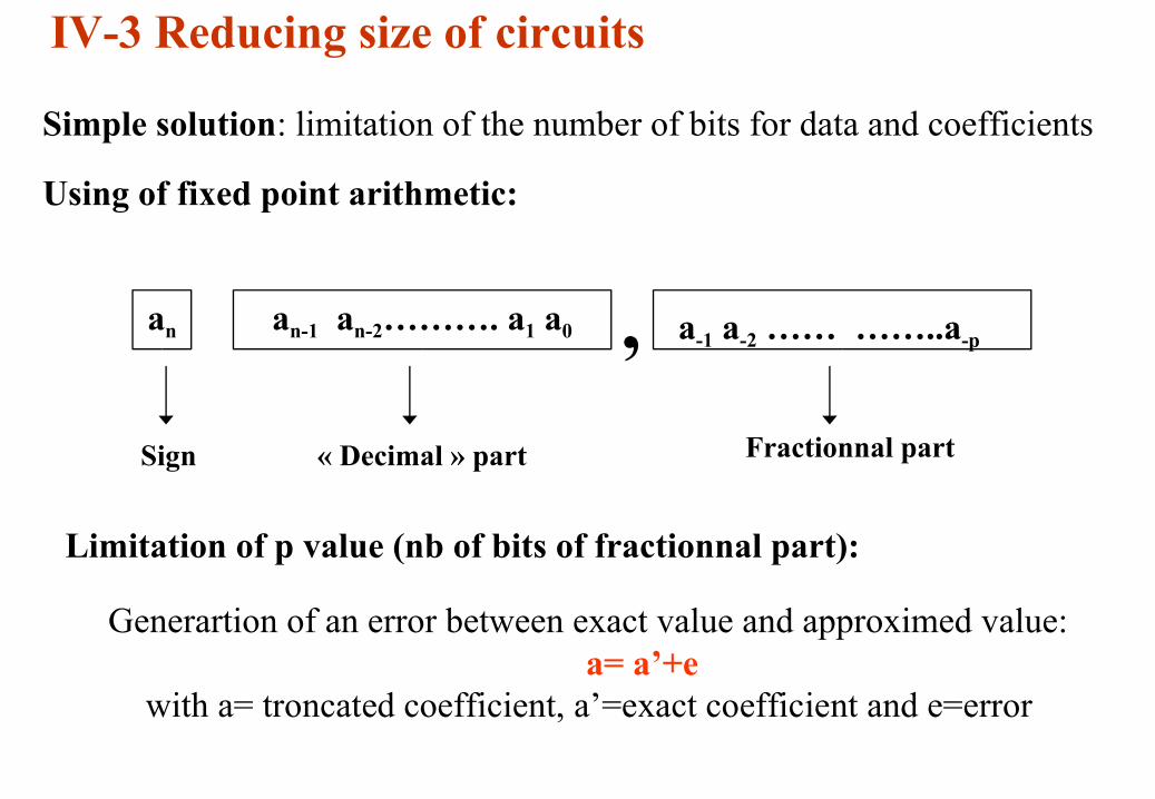
IV-3 Reducing size of circuits
Simple solution: limitation of the number of bits for data and coefficients
Using of fixed point arithmetic:
an an-1 an-2………. a1 a0 , a-1 a-2 …… ……..a-p
Sign « Decimal » part Fractionnal part
Limitation of p value (nb of bits of fractionnal part):
Generartion of an error between exact value and approximed value:a= a’+e
with a= troncated coefficient, a’=exact coefficient and e=error

Example:
a’=0.26
P=1 a=(0.5)10=(0.1)2 e=0.24P=2 a=(0.25)10=(0.01)2 e=-0.01P=3 a=(0.25)10=(0.010)2 e=-0.01P=4 a=(0.3125)10=(0.0101)2 e=0.0525P=5 a=(0.28125)10=(0.01001)2 e=0.0215P=6 a=(0.265625)10=(0.010001)2 e=0,005625P=7 a=(0.2578125)10=(0.0100001)2 e=-0.0021875P=8 a=(0.26171875)10=(0.01000011)2 e=0.00171875
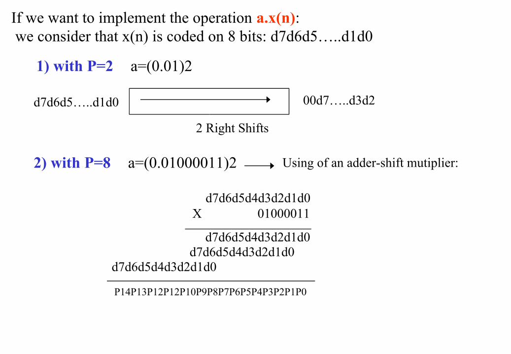
If we want to implement the operation a.x(n): we consider that x(n) is coded on 8 bits: d7d6d5…..d1d0
1) with P=2 a=(0.01)2
2 Right Shifts
d7d6d5…..d1d0 00d7…..d3d2
2) with P=8 a=(0.01000011)2 Using of an adder-shift mutiplier:
d7d6d5d4d3d2d1d0X 01000011
d7d6d5d4d3d2d1d0d7d6d5d4d3d2d1d0
d7d6d5d4d3d2d1d0
P14P13P12P12P10P9P8P7P6P5P4P3P2P1P0

We consider the following digital filter:y(n)= x(n) + 0.3y(n-1) – 0.02y(n-2)
5) Compute the Transfer Function H1(z) of this filter6) Give the schematic of this filter7) We want to accelerate this filter using the Scattered look-ahead pipelining. Give the new Transfer Function H2(z) of this filter for a pipeline M=34) Give the schematic of this new filter5) We want to evaluate the number of operators corresponding to the calculation of 0.3y(n-1) . If we consider that the coefficient (0.3) and y(n-1) are coded on 8 bits, give the schematic of this operation.
Example of problem

I- Objectives of the Real Time Image Processing II- Algorithm To Architecture Methodology
III- Digital filters applied to Image Processing
IV- Signal and Image Processing Algorithms Optimization
V- FPGA Implementation of Real Time Image Processing Algorithms using VHDL
OUTLINEOUTLINE

V-1 VHDL PresentationV-1-1 Introduction
-VHDL= VHSIC Hardware Description Language-VHSIC= Very High Scale Integrated Circuit
-VHDL developed at the end of seventies by DOD (DOD=USA Departement of Defense)
-First Standard: IEEE 1076 in 1987-Second Standard: IEEE 1164 in 1993 (multi-valuated Logic)
VHDL Advantages vs Schematic description: - High level description: fast debug - Flexibility: Intelectual Property (IP) Re-Use - Choice of tools (Cadence, Mentor Graphics, …..) - Choice of suppliers (FPGA: Xilinx, Altera….. and
ASIC: STmicrolectronics, AMS, ….) - VHDL block can be included inside a schematic - Infinite logic gates (difficult in schematic > 10K gates)

3 Different description levels:
- VHDL level (High level):
-> VHDL Behavioral: procedurale description-> VHDL structural or RTL (Register To Logic)
- Transistors level: layout
- Schematic level: description with logic cellsa
s
by

- Structure of VHDL language: Entity/Architecture pair:
-- Libraries declarations:library IEEE;use IEEE.STD_LOGIC_1164.ALL;
-- External logic block description:entity component_name is Port (list of input/output );end component_name;
-- Internal logic block description :architecture component_name _arch of component_name is[external components declaration][ types declaration][signals declaration] ……..begin description area of the componentend component_name;

a1b0ys _
.. sbsay +=⇒a
s
by
mux21 1 bit:
a0
a7
b7
y7
y0
b0
s
mux21 8 bits:
V-1-2 Description in Behavorial VHDL of elementary functions
a) Multiplexer 2 to 1

-- Multiplexer 2 to 1:
library IEEE;use IEEE.STD_LOGIC_1164.ALL;
entity mux21_1 is Port ( a : in std_logic_vector(7 downto 0); b : in std_logic_vector(7 downto 0); s : in std_logic; y : out std_logic_vector(7 downto 0));end mux21_1;
architecture mux2_1_arch of mux21_1 isbegin y<=a when (s='1') else b;end mux2_1_arch;
Mux21
a
b
7
7
7
1
y
s

b) Adder
-> Ripple Carry Adder:
11111
01011
01101
10001
01110
10010
10100
00000
sici+1ciaibi
Full Adder (FA) 1 bit
si=ai xor bi xor ci
ci+1=ci.ai or bi.ci or bi.ai
ci
bi
ai ci+1
si
FA

-> Adder 4 bits:
FA FAFA FA
c0a0b0a1b1a2b2a3b3
s0s1s2s3c4
-- Additionneur à propagation de retenue 4 bits
library IEEE;use IEEE.STD_LOGIC_1164.ALL;
entity add4 is Port ( a : in std_logic_vector(3 downto 0); b : in std_logic_vector(3 downto 0); cin : in std_logic; s : out std_logic_vector(3 downto 0); cout : out std_logic);end add4;

architecture add4_arch of add4 issignal c: std_logic_vector(4 downto 0);begin process(a,b,cin) begin c(0) <= cin; for i in 0 to 3 loop s(i) <= a(i) xor b(i) xor c(i); c(i+1) <= (c(i) and b(i)) or (c(i) and a(i)) or (b(i) and a(i)); end loop; cout <= c(4); end process;end add4_arch;
-- Sequential mode

c) Register:library IEEE;use IEEE.STD_LOGIC_1164.ALL;
entity register is Port ( clk : in std_logic; D: in std_logic_vector(7 downto 0); Q : out std_logic_vector(7 downto 0));end register;D
Register
Q8
8
clkarchitecture register_arch of register isbegin bascule3: process(clk) begin if rising_edge(clk) then -- IEEE1164 function Q <= D; end if; end process;end register_arch;

V-2 FPGA Implementation of Real Time Image Processing Algorithms using VHDL
V-2-1 FPGA description:- Examples from Xilinx (www.XIlinx.com): Spartan and Virtex Families- Xilinx tools (VHDL, Simulation, bitstream generation):
Webpack and Modelsim (free)
V-2-2 Filter Implementation:
x(n)h(n)
y(n)=x(n) * h(n)
Example: y(n)=x(n) +(5/4).y(n-1) – (3/8).y(n-2) with x(n) coded on 8 bits and y(n) coded on 16 bits

+
D
x
y(n)
Dx(n)
x
+
45
83
−
a) Schematic solution
b) VHDL solutionlibrary IEEE;use IEEE.STD_LOGIC_1164.ALL;use IEEE.STD_LOGIC_ARITH.ALL;use IEEE.STD_LOGIC_UNSIGNED.ALL;
entity filter is Port ( clk : in std_logic; x: in unsigned(7 downto 0); y : out unsigned(15 downto 0));end filter;

architecture filtre_arch of filtre issignal y1, y2, ytemp: unsigned (y’range);beginprocess(clk) begin if rising_edge(clk) then
ytemp <= x+ shr((y1+y1+y1+y1+y1),"100") - shr((y2+y2+y2),"1000");y2<=y1;y1<=ytemp;
end if; end process;y <= ytemp;end filtre_arch;