real-time hardware-in-the-loop simulation … · real-time hardware-in-the-loop simulation for...
TRANSCRIPT

REAL-TIME HARDWARE-IN-THE-LOOP SIMULATION FOR DRIVABILITY DEVELOPMENT
Yun Liu, Sung Kwon Hong, Tony Ge
Ford Motor Company
dSPACE Technology Conference
October 18, 2017
Plymouth, MI, USA

2
Agenda
� Introduction∗ Drivability development challenges and HIL approach
� Drivability HIL Simulation Requirement∗ Drivability Hardware-in-the-loop simulation approach∗ Vehicle CAE model requirement∗ HIL hardware requirement
� CAE Models and HIL Simulation Process∗ Multi-disciplinary CAE plant models ∗ HIL simulators and powertrain controller module (PCM) interfaces setup∗ Drivability HIL test process and result
� Summary
� Acknowledgements

3
Introduction
� Drivability is a measure of vehicle capability to achieve desired response to driving events. The response is mainly related to longitudinal acceleration of the vehicle.
� Examples of drivability phenomenon
* Tip-in / Tip-out* Gear Change* Start-up / Shut-down
� Smooth and controlled transient is expected as entire vehicle dynamical system responds to changing driver, controller or environment inputs.
� Objective drivability evaluation tools can quantify the transient behavior and is becoming a standard vehicle calibration sign-off procedure

4
Drivability Development
� Vehicle system interaction
∗ Powertrain and chassis hardware
∗ Control strategy
∗ Driver interfaces
� Challenges of drivability development
∗ Evaluation and calibration usually happens on prototype vehicles
∗ Physical tests are associated with considerable time and resource cost
∗ Design change options are limited and expensive in late product development cycle
∗ Early design phase methods do not address the problem comprehensively
∗ Closed-loop interaction between vehicle system and controller not represented well
� Model based system engineering approach
∗ Process goal: evaluate drivability with full vehicle CAE models and complete control strategy
∗ Provide analysis tool to component and control design before committing to hardware
Drivability
5
Drivability HIL Simulation Process
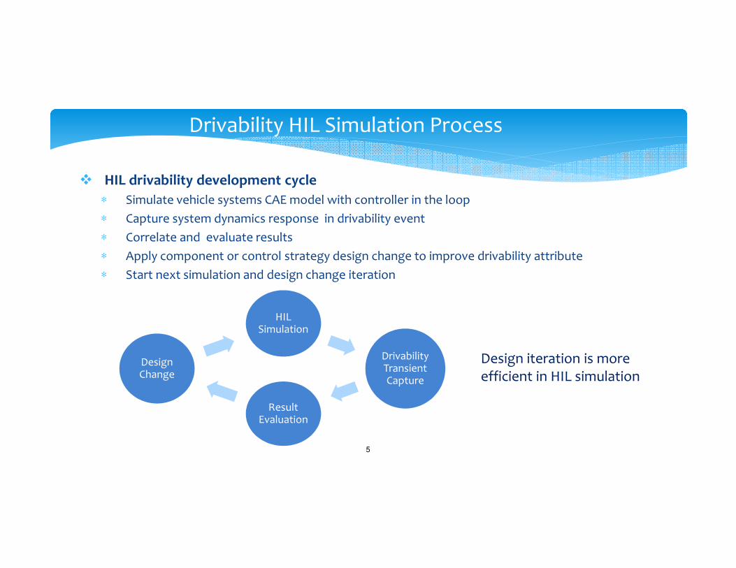
� HIL drivability development cycle
∗ Simulate vehicle systems CAE model with controller in the loop
∗ Capture system dynamics response in drivability event
∗ Correlate and evaluate results
∗ Apply component or control strategy design change to improve drivability attribute
∗ Start next simulation and design change iteration
HIL Simulation
Drivability Transient Capture
Result Evaluation
Design Change
Design iteration is more efficient in HIL simulation

6
Drivability HIL System Requirement
Technical requirements of HIL
� Key enabling technology: Vehicle CAE models
∗ Degrees-of-freedom and accuracy to capture drivability transient frequency range (below 20-30 Hz)
∗ Mostly physics based for transient state change, not steady state map
∗ Powertrain models tightly coupled with controller
� CAE model and controller integration: HIL simulators and IO hardware
∗ High performance computing platform with multi-core parallel processing
∗ High speed inter-processor data sharing architecture
∗ IO signals drivers for data exchange between CAE models and powertrain control module
CAE Model Real Time Simulator PCM

7
Multidisciplinary CAE Model Setup
� CAE modeling tools selection
∗ Represent vehicle behavior in the required frequency range
∗ Efficient real time solver to execute on available HIL simulator targets
∗ Existing experience, building time, maintenance cost
� Solution example for a target vehicle
∗ Ricardo WAVE-RT 2.0L engine plant model in thermal fluid physics domain
∗ GT-SUITE 6 speed transmission mechanical and electrohydraulic plant model
∗ SIMPACK multi-body dynamics vehicle chassis model: mechanical and high DOF

8
Real Time Engine Model
� Real time engine models in HIL
∗ Mean value engine models are extensively applied in HIL but limited to cycle average torque
∗ To represent torque transient in the required frequency band, a crank-angle resolved and cylinder independent engine model will meet the goal
� Drivability HIL engine model
∗ Target engine is turbo charged 2.0L 4-cylinder gasoline with direct fuel injection.
∗ Detailed 1-D WAVE engine model is simplifiedand exported to WAVE-RT as standard C codeand S-function
∗ The WAVE-RT model simulates 1-D air path and crank angle resolved torque from individualcylinder
Engine torque pulses with 0 crossing between cylinder combustion cycles

9
Transmission driveline CAE Model
� Target application: 6 speed automatic front wheel drive∗ Torque converter model and lock-up clutch∗ Gear shift clutches and hydraulics circuit ∗ Gearbox, shaft and axles
� Integrated GT-SUITE transmission plant model∗ Full driveline analysis model in multi-physics
domain with nonlinear components∗ Improved library components and
real time solver in latest release and real-timecapable on newer simulator target.

10
Vehicle Chassis and Tire MBD CAE Model
� Multibody dynamics for drivability
∗ 3D Tire components
∗ Powertrain and chassis body
∗ Mounts, suspension, bushings
∗ Need a higher DOF model than commonvehicle motion dynamics simulation
� Real time SIMPACK MBD model
∗ 159 DOFs white box physical model
∗ No code generation or compilation required
∗ Real time solver execution directly on Linux OS
∗ Built-in parallel computing on multiple cores
Real time task viewer of MBD vehicle model solver

11
HIL Simulators System Configuration
� HIL Hardware interacts with model simulation and affects CAE performance
� HIL Simulators∗ High performance multi-core computers with real-time OS∗ I/O device drivers to emulate sensors, actuators, network and bus signals∗ HIL user interfaces and test environment∗ Drivability HIL simulators: dSPACE DS1006, SCALEXIO, Concurrent Real Time Linux workstation
� I/O boards between plant model and PCM∗ Automotive sensors, encoders∗ Current, voltage measurements∗ CAN/LIN/Ethernet interfaces
� HIL host computer∗ Test environment with real time simulator interfaces∗ PCM calibration tool interface

12
HIL Simulation: Integrity Test
� Verify CAE models are integrated correctly with control strategy
� HIL signals connection validation∗ Component plant model physical signals
∗ Controller signals wiring and conversion to plant model
∗ PCM diagnostics code history
� Standard drivability test sequence checkoutbasic plant model and PCM state variables
� Complete integrity testcompare all model and PCM variables like engine air flow, temperatures, clutch pressure, acceleration.

13
HIL Simulation: Drivability Events in Detail
Drivability events are usually transient behavior
Tip-in with slipping torque converter clutch Gear Shift
Transient states: air pressure, fuel flow, torque, speed, vehicle accel, clutch pressure, … Control and calibration: throttle, injector, spark, VCT, waste gate, slip, gear, command pressure, PWM currents,… Model Parameters: air path, inertia, stiffness, converter map, clutch friction, hydraulics volume and preload, …
14
Summary
� This work applies HIL method to powertrain drivability attribute development.
� CAE models, controller module and HIL simulation tools are integrated and results show the technical possibilities and potential application process.
� HIL approach is a feasible method for drivability development. There are many benefits shifting vehicle tests to virtual simulation.
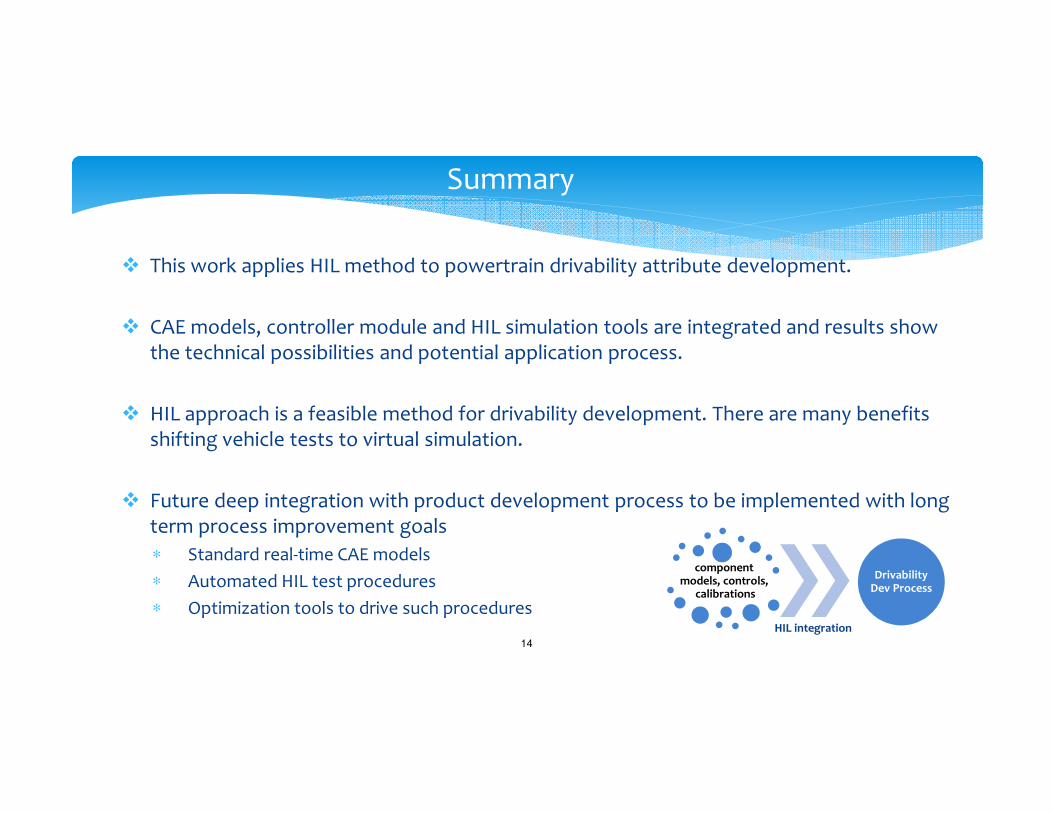
� Future deep integration with product development process to be implemented with long term process improvement goals
∗ Standard real-time CAE models
∗ Automated HIL test procedures
∗ Optimization tools to drive such procedures
component models, controls,
calibrations
HIL integration
Drivability Dev Process

Thank You!QUESTIONS?
16