readme supplement version 7 - sst systems, inc. · 2015-12-17 · 1 readme supplement . version 7.0...
TRANSCRIPT

1
Readme Supplement
Version 7.0 Disclaimer Please read the following carefully:
This software and this document have been developed and checked for correctness and accuracy by SST Systems, Inc. (SST) and InfoPlant Technologies Pvt. Ltd. (InfoPlant). However, no warranty, expressed or implied, is made by SST and InfoPlant as to the accuracy and correctness of this document or the functioning of the software and the accuracy, correctness and utilization of its calculations.
Users must carry out all necessary tests to assure the proper functioning of the software and the applicability of its results. All information presented by the software is for review, interpretation, approval and application by a Registered Professional Engineer.
CAEPIPE is a trademark of SST and InfoPlant.
CAEPIPE Version 7.0, © 2013, SST Systems, Inc. and InfoPlant Technologies Pvt. Ltd. All Rights Reserved.
SST Systems, Inc. Tel: (408) 452-8111 1798 Technology Drive, Suite 236 Fax: (408) 452-8388 San Jose, California 95110 Email: [email protected] USA www.sstusa.com InfoPlant Technologies Pvt. Ltd. Tel: +91-80-40336999 7, Crescent Road Fax: +91-80-41494967 Bangalore – 560001 Email: [email protected] India www.infoplantindia.com

2
Annexure A Code Compliance

3
Power Piping ASME B31.1 (2012)
Allowable Pressure At this time, there is no provision in CAEPIPE to specify the type of pipe construction, i.e., whether the pipe is a seamless or longitudinal welded or spiral welded. Accordingly, irrespective of the type of pipe construction, CAEPIPE calculates allowable pressure as follows.
For straight pipes and bends with seamless construction or designed for sustained operation below the creep range, Eq. (9) of para.104.1.2 is used as given below to compute allowable pressure.
ao
aa YtD
SEtP
22−
=
For straight pipes and bends designed for sustained operation within the creep range, Eq. (11) of para.104.1.4 is used as given below to calculate allowable pressure.
ao
aa YtD
SEWtP
22−
=
where
Pa = allowable pressure
SE = allowable stress as given in Appendix A of B31.1 (2012) Code, where
E = weld joint efficiency factor or casting quality factor as given in Table 102.4.3
ta = available thickness for pressure design = tn × (1 - mill tolerance/100) - corrosion allowance
(Any additional thickness required for threading, grooving, erosion, corrosion, etc., should be included in corrosion allowance in CAEPIPE)
tn = nominal pipe thickness
Do = outside diameter of pipe
d = inside diameter of pipe
The Pressure coefficient Y is implemented as per Table 104.1.2 (A). In addition,
Y = 0.0, for cast iron and non-ferrous materials.
oDddY+
= , if Do/ta < 6, for ferritic and austenitic steels designed for temperatures of 900oF (480oC)
and below
W = weld strength reduction factor as per Table 102.4.7. Refer to Annexure B for details on Weld strength reduction factor implemented in CAEPIPE.
For closely spaced miter bends, the allowable pressure is calculated from Eq. (C.3.1) of para.104.3.3.
)2/()(
rRrrRSEt
P aa −
−=
where
r = mean radius of pipe = (Do - tn)/2
R = equivalent bend radius of the miter

4
For widely spaced miter bends, the allowable pressure is calculated from Eq. (C.3.2) of para. 104.3.3.
)tan25.1(
2
aa
aa rttr
SEtP
θ+=
Where, θ = miter half angle
Sustained Stress The stress (SL) due to sustained loads (pressure, weight and other sustained mechanical loads) is calculated from Eq. 15 of para.104.8.1
hA
n
oL S
ZiM
tPD
S ≤+=75.0
4
where
P = maximum of CAEPIPE pressures P1 through P10
Do = outside diameter
tn = nominal wall thickness
i = stress intensification factor. The product 0.75i shall not be less than 1.0.
MA = resultant bending moment due to weight and other sustained loads
Z = uncorroded section modulus; for reduced outlets, effective section modulus as per para. 104.8.4
Sh = hot allowable stress at maximum CAEPIPE temperature [i.e., at max (Tref, T1 through T10)]
Occasional Stress The stress (SLo) due to occasional loads is calculated from Eq. 16 of para.104.8.2 as the sum of stress due to sustained loads (SL) and stress due to occasional loads (So) such as earthquake or wind. Wind and earthquake are not considered concurrently.
hBA
n
opeakLo S
ZiM
ZiM
tDP
S 2.175.075.04
≤++=
where
MB = resultant bending moment on the cross-section due to occasional loads such as thrusts from relief / safety valve loads, from pressure and flow transients, earthquake, wind etc.
Ppeak = peak pressure = (peak pressure factor in CAEPIPE) x P
Expansion Stress Range (i.e., Stress due to Displacement Load Range) The stress (SE) due to thermal expansion is calculated from Eq. 17 of para.104.8.3.
AC
E SZ
iMS ≤=
where
MC = resultant moment due to thermal expansion
)25.025.1( hCA SSfS += , from Eq. (1A) of para. 102.3.2 (B)
=f cyclic stress range reduction factor from Eq.(1C) of para. 102.3.2(B),
=f 6/N0.2 <= 1.0 and f >= 0.15 with N being the total number of equivalent reference displacement stress range cycles expected during the service life of the piping
SC = basic allowable stress as minimum metal temperature expected during the displacement cycle under analysis

5
Sh = basic allowable stress as maximum metal temperature expected during the displacement cycle under analysis
When Sh is greater than SL, the allowable stress range may be calculated as
])(25.1[ LhCA SSSfS −+= , from Eq. (1B) of para. 102.3.2 (B)
This is specified as an analysis option: “Use liberal allowable stresses”, in the menu Options->Analysis on the Code tab of CAEPIPE.
Note:
Refer Annexure C for the details of “Thickness” and the “Section Modulus” used for weight, pressure and stress calculations.

6
ASME B31.1 – 2012

7
ASME B31.1 – 2012

8
ASME B31.1 – 2012

9
ASME B31.1 – 2012

10
ASME B31.1 – 2012

11
Process Piping ASME B31.3 (2012)
Allowable Internal Pressure For straight pipes and bends, the allowable pressure is calculated using Eq. (3a) for straight pipes and Eq. (3c) with I = 1.0 for bends from paras. 304.1.2. and 304.2.1. respectively.
a
aa YtD
SEWtP
22−
=
where
Pa = allowable pressure
S = allowable stress as provided in para. 302.3.1 (a) and as per Table A-1
E = joint factor (input as material property) from Table A-1A or A-1B from para. 302.3.3. and para. 302.3.4.
W = Weld Joint Strength Reduction Factor from para. 302.3.5 (e) and as per Table 302.3.5 is implemented in CAEPIPE as follows. Tmax below denotes maximum operating temperature (i.e., max of T1 through T10 and Tref in CAEPIPE).
With Material Type in CAEPIPE = CS [CrMo]
W = 1.0 with Tmax <= 8000 F (or 4270 C)
W = 0.64 with Tmax > 12000 F (or 6490 C) and
For Tmax > 8000 F (or 4270 C) and <= 12000 F (or 6490 C), the values of W are taken from Table 302.3.5.
W for intermediate temperatures are linearly interpolated.
With Material Type in CAEPIPE = FS [CSEF (Subcritical)]
W = 1.0 with Tmax <= 9000 F (or 4820 C)
W = 0.5 with Tmax > 9000 F (or 4820 C)
With Material Type in CAEPIPE = AS or NA
W = 1.0 with Tmax <= 9500 F (or 5100 C)
For Tmax > 9500 F (or 5100 C), the values of W are taken as per Table 302.3.5.
W for intermediate temperatures are linearly interpolated.
With Material Type in CAEPIPE = SS
W = 1.0 with Tmax <= 15000 F (or 8160 C)
For Other Material Types in CAEPIPE
W = 1.0 with Tmax <= 8000 F (or 4270 C)
W = 1 – 0.000909 (Tmax – Tcr) for Tmax > 8000 F (or 4270 C) and <= 15000F (or 8100C)
where, Tcr is taken as 8000 F
ta = available thickness for pressure design
= tn × (1 - mill tolerance/100) - corrosion allowance “c”
(Any additional thickness required for threading, grooving, erosion, corrosion, etc. should be included in corrosion allowance in CAEPIPE)
tn = nominal pipe thickness
D = outside diameter

12
d = inside diameter
Y = Pressure coefficient from Table 304.1.1, valid for ta < D/6, and
cdDcdY2
2++
+= , valid for 6/Dta ≥
For closely spaced miter bends, the allowable pressure is calculated using Eq. (4b) from para. 304.2.3.
)2/()(
rRrrRSEWt
P aa −
−=
where
r = mean radius of pipe = (D - tn)/2 R = effective bend radius of the miter (see para. 304.2.3 of code for definition)
For widely spaced miter bends, the allowable pressure is calculated using Eq. (4c) from para. 304.2.3 as
)tan25.1(
2
aa
aa rttr
SEWtP
θ+=
where
θ = miter half angle
Sustained Stress The stress (SL) due to sustained loads (pressure, weight and other sustained mechanical loads) is calculated using Eq. (23a) and (23b) from para. 320.2 and para. 302.3.5 (c).
htbaL SSSSS ≤++= 22 )2()|(|
where
Sustainedpssustainedp
aaa A
Rt
PDAFIS
+=
=
4
Sustainedm
ooiib Z
MIMIS
+=
22 )()(
Sustainedm
ttt Z
MIS
=
2
P = maximum of CAEPIPE input pressures P1 through P10
D = outside diameter
ts = wall thickness used for sustained stress calculation after deducting corrosion allowance from the nominal thickness
ts = nominal thickness – corrosion allowance in CAEPIPE, as per para. 320.1
=pA corroded cross-sectional area of the pipe computed using ts as per para. 320.1.
=aI longitudinal force index = 1.0
=aF longitudinal force due to sustained loads (pressure and weight)

13
R = axial force due to weight
=iI in-plane stress intensification factor; the product of ii75.0 shall not be less than 1.0
=oI out-of-plane stress intensification factor; the product of oi75.0 shall not be less than 1.0
=tI torsional moment index = 1.0
=iM in-plane bending moment due to sustained loads e.g., pressure and weight
=oM out-of-plane bending moment due to sustained loads e.g., pressure and weight
=tM torsional moment due to sustained loads e.g., pressure and weight
Zm = corroded section modulus as per para. 320.1; for reduced outlets / branch connections, effective section modulus
Sh = hot allowable stress at maximum temperature [i.e., at Max(Tref, T1 through T10)]
Sustained plus Occasional Stress The stress (SLo) due to sustained and occasional loads is calculated as the sum of stress due to sustained loads such as due to pressure and weight (SL) and stress due to occasional loads (So) such as due to earthquake or wind. Wind and earthquake are not considered concurrently (see para. 302.3.6(a)).
For temp <= 4270 C or 8000 F
hLo SS 33.1≤
For temp > 4270 C or 8000 F
yLo WSS 9.0≤
where
OLLo SSS += , where SL is computed as above, and
22 )2()|(| toboaoo SSSS ++=
Occasionalps
peak
occasionalp
aaao A
Rt
DPPAFI
S
+
−=
=
4)(
Occasionalm
ooiibo Z
MIMIS
+=
22 )()(
Occasionalm
ttto Z
MIS
=
2
Ppeak = peak pressure = (peak pressure factor in CAEPIPE) x P
R = axial force due to occasional loads such as earthquake or wind
=iM in-plane bending moment due to occasional loads such as earthquake or wind
=oM out-of-plane bending moment due to occasional loads such as earthquake or wind
=tM torsional moment due to occasional loads such as earthquake or wind
Sy = yield strength at maximum temperature (i.e., max(Tref, T1 through T10)

14
W = 1.0 for Austenetic stainless steel and 0.8 for all other materials as per para.302.3.6(a)
Expansion Stress The stress (SE) due to thermal expansion is calculated using Eq. 17 from para. 319.4.4
AtbaE SSSSS ≤++= 22 )2()|(|
where
Expansion
aaa A
FIS
=
Expansion
ooiib Z
MIMIS
+=
22 )()(
Expansion
ttt Z
MIS
=
2
=A un-corroded cross-sectional area of the pipe/fitting computed using nominal thickness tn and outer diameter D, as per para. 319.3.5.
=aI axial stress intensification factor = 1.0 for elbows, pipe bends and miter bends and Ia = io for other components as listed in Appendix D of B31.3 (2012)
=aF range of axial forces due to displacement strains between any two thermal conditions being evaluated
=iI in-plane stress intensification factor
=oI out-of-plane stress intensification factor
=tI torsional stress intensification factor = 1.0
=iM in-plane bending moment
=oM out-of-plane bending moment
=tM torsional moment
Z = uncorroded section modulus as per para. 319.3.5; for reduced outlets/branch connections, effective section modulus as per para. 319.4.4 (c)
)25.025.1( hCA SSfS += , Eq. (1a) of para. 302.3.5(d)
=f stress range reduction factor from Eq. (1c) of para. 302.3.5 (d) = 6N-0.2
where f >= 0.15 and f <= 1.0 (see Note 1 below)
SC = basic allowable stress as minimum metal temperature expected during the displacement cycle under analysis
Sh = basic allowable stress as maximum metal temperature expected during the displacement cycle under analysis
When Sh is greater than SL, the allowable stress range may be calculated as
])(25.1[ LhCA SSSfS −+= , Eq. (1b) of para. 302.3.5(d).

15
This is specified as an analysis option “Use liberal allowable stresses”, in the menu Options->Analysis on the CAEPIPE Code tab.
Notes:
1. As per para. 302.3.5 (d), f = maximum value of stress range factor; 1.2 for ferrous materials with specified minimum tensile strengths <= 517 MPa (75 ksi) and at Metal temperatures <= 3710 C (7000
F). This criterion is not implemented in CAEPIPE as the provision for entering the minimum tensile strength in material property is not available at this time. Hence f <= 1.0 for all materials including Ferrous materials.
2. Refer Annexure C for the details of “Thickness” and the “Section Modulus” used for weight, pressure and stress calculations.

16

17

18
19

20
Pipeline Transportation Systems for Liquids and Slurried ASME B31.4 (2012)
Allowable Pressure For straight pipes and bends (including closely spaced and widely spaced miter bends), the allowable pressure is calculated from para. 403.2.1.
DSEt
P ai
2=
where
Pi = allowable pressure
S = allowable stress = 0.72 Sy
Sy = specified minimum yield strength of pipe
E = weld joint factor as defined in Table 403.2.1-1
ta = available thickness for pressure design
= tn × (1 - mill tolerance/100) - sum of allowances, as per para. 403.2.1, for corrosion, threading, grooving and erosion.
D = outside diameter
Stress due to Sustained Loads (Unrestrained Piping) For Pipes (as per para. 402.6.2)
SyZ
MMiMiA
Ft
PDSSustained
tooii
Sustained
a
nL 75.0
)()()(4
222
≤
++++= as per Table 403.3.1-1
where
=ii in-plane stress intensification factor = 1.0 for pipes
=oi out-of-plane stress intensification factor = 1.0 for pipes
For Fittings & Components.(as per para. 402.6.2)
SyZ
MMiMiA
Ft
PDSSustained
tooii
Sustained
a
nfcL 75.0
)()75.0()75.0(4
222
)( ≤
++++= as per Table 403.3.1-1
where
P = maximum operating pressure = max of CAEPIPE input pressures (P1 through P10). Due considerations shall be given as per para. 401.2.2.2 while inputting pressure values in CAEPIPE.
D = outside diameter
tn = nominal thickness as per para. 402.1
=ii in-plane stress intensification factor; the product ii75.0 shall not be less than 1.0
=oi out-of-plane stress intensification factor; the product oi75.0 shall not be less than 1.0
=iM in-plane bending moment
=oM out-of-plane bending moment
Mt = torsional moment
Z = uncorroded section modulus; for reduced outlets, effective section modulus

21
Fa = axial force component for external loads
A = nominal cross-section area
Sy = specified minimum yield strength of pipe
Stress due to Sustained Loads + Occasional Loads (Unrestrained Piping) For Pipes (as per para. 402.6.2)
y
occasional
tooii
occasional
a
n
peakLLo S
ZMMiMi
AF
tDPP
SS 8.0)()()(
4)( 222
≤
++++
−+= as per Table 403.3.1-1
For Fittings & Components (as per para. 402.6.2)
y
occasional
tooii
occasional
a
n
peakfcLLo S
ZMMiMi
AF
tDPP
SS 8.0)()75.0()75.0(
4)( 222
)( ≤
++++
−+=
as per Table 403.3.1-1
where
Ppeak = peak pressure = (peak pressure factor x P) where P = maximum operating pressure, as defined above with 1.0 <= peak pressure factor <= 1.1 as per para. 403.3.4
Expansion Stress (Unrestrained Piping) The stress (SE) due to thermal expansion is calculated from para.402.5.2
AtbE SSSS ≤+= 22 4 as per Table 403.3.1-1 and para. 403.3.2
where
=bS resultant bending stress = Z
MiMi ooii22 )()( +
=tS torsional stress = Z
M t
2
Mt = torsional moment
Z = uncorroded section modulus; for reduced outlets, effective section modulus
Please note, “Liberal allowable” option is always turned ON for ANSI B31.4.
])(25.1[ LhCA SSSfS −+=
=f stress range reduction factor = 6/N0.2, where N = number of equivalent full range cycles
where f <= 1.2 (from para. 403.3.2).
Sc = 0.67Sy at the lower of the installed temperature or minimum operating temperature
Sh = 0.67Sy at the higher of the installed temperature or maximum operating temperature
where
Sy = specified minimum yield strength of pipe

22
Stress due to Sustained, Thermal and Occasional Loads (Restrained Piping) The Net longitudinal stress (SL) due to sustained, thermal expansion and occasional loads for restrained piping is calculated from para. 402.6.1
ycoldestTwarmestT
OccasionalBxpBxp
sustainedBxpBxpL
SSS
SSSSSS
SSSSSSS
9.0),max(
),max(
),max(
≤
+−+++
+−+++=
where
Pressure stress = n
p tPDS2
υ= where 3.0=υ as per para. 402.2.3 and can be either positive or
negative
Stress due to axial loading (other than temperature and pressure) = AFS a
x = and can be positive or
negative. Nominal bending stress SB from Weight and / or other External loads for
For Pipes
ZMMiMi
S tooiiB
222 )()()( ++=
For Fittings & Components.
ZMMiMi
S tooiiB
222 )()75.0()75.0( ++=
Thermal expansion stress = )( oiT TTES −= α , which can be either positive or negative where
P = maximum operating pressure = max (P1 through P10)
D = outside diameter
tn = nominal thickness
=ii in-plane stress intensification factor; the product ii75.0 shall not be less than 1.0
=oi out-of-plane stress intensification factor; the product oi75.0 shall not be less than 1.0
=iM in-plane bending moment
=oM out-of-plane bending moment
Mt = torsional moment
Fa = axial force component for external loads
A = nominal cross-section area
Z = uncorroded section modulus; for reduced outlets, effective section modulus
Sy = specified minimum yield strength of pipe
Ti = installation temperature = Tref in CAEPIPE
To = warmest or coldest operating temperature
=α coefficient of thermal expansion at To defined above E = young’s modulus at ambient (reference) temperature

23
Note: 1. Para. 402.6.2 of B31.4 (2012) states that “Longitudinal stress from pressure in an
unrestrained line should include consideration of bending stress or axial stress that may be caused by elongation of the pipe due to internal pressure and result in stress at bends and at connections and produce additional loads on equipment and on supports”. The above statement seems to imply that “elongation of pipe and opening of bends due to Bourdon effect” are to be included in the Sustained load case (and hence in Operating case and Sustained plus Occasional load case). On the other hand, since the deformation due to Bourdon effect is being constrained by piping supports, CAEPIPE includes the Bourdon effect as part of the results for Thermal Expansion (when “Solve Thermal Case” is opted) or as part of the Operating Case (when “Thermal = Operating – Sustained is opted).
2. Young’s modulus of elasticity corresponding to reference temperature (Tref) is used to form the stiffness matrix in accordance with para. 402.2.2.
3. Refer Annexure B for the details of “Thickness” and the “Section Modulus” used for weight, pressure and stress calculations.

24

25

26

27
Refrigeration Piping and Heat Transfer Components ASME B31.5 (2013)
Allowable Pressure For straight pipes and bends (including closely spaced and widely spaced miter bends), the allowable pressure is calculated from para. 504.1.2.
a
a
YtDSEt
P2
2−
=
where
P = allowable pressure
S = basic allowable stress at maximum of CAEPIPE input temperatures T1 through T10
E = longitudinal or spiral joint factor (input as material property) from para. 502.3.1 and Table 502.3.1
Table 502.3.1 provides maximum allowable hoop stress values (SE) as a function of metal temperature and includes Longitudinal or Spiral Joint Factor (E) for various materials. Divide SE value by E value provided in Table 502.3.1 to obtain basic allowable stress S. For materials where E is not given explicitly in Table 502.3.1, use E=1.0.
Hence, SE in the above formula for allowable pressure P is the allowable hoop stress per para. 502.3.1 and Table 502.3.1.
ta = available thickness for pressure design (as per para. 504.1.1)
= tn × (1 - mill tolerance/100) - corrosion allowance
(Any additional thickness required for threading, grooving, erosion, corrosion, etc., should be included in corrosion allowance)
tn = nominal pipe thickness
D = outside diameter
d = inside diameter
Y = pressure coefficient
For ductile non-ferrous materials and ferritic and austenitic steels,
Y = 0.4 for 6/ ≥atD and Y = Dd
d+
, for 6/4 <≤ atD
For Cast Iron, Y = 0.0
Sustained Stress (in corroded condition) The stress (SL) due to sustained loads (pressure, weight and other sustained mechanical loads) is calculated from para. 502.3.2(d). Also, refer to Note 1 below.
hc
ooii
cL S
ZMiMi
tPDS ≤
++=
22 )()(4
where
P = maximum of CAEPIPE input pressures P1 through P10
D = outside diameter
tc = nominal thickness – corrosion allowance, as per para. 502.3.2 (d)
=ii in-plane stress intensification factor
=oi out-of-plane stress intensification factor
28
=iM in-plane bending moment
=oM out-of-plane bending moment
Zc = corroded section modulus as per para. 502.3.2 (d)
Sh = basic allowable stress at maximum of CAEPIPE input temperatures T1 through T10
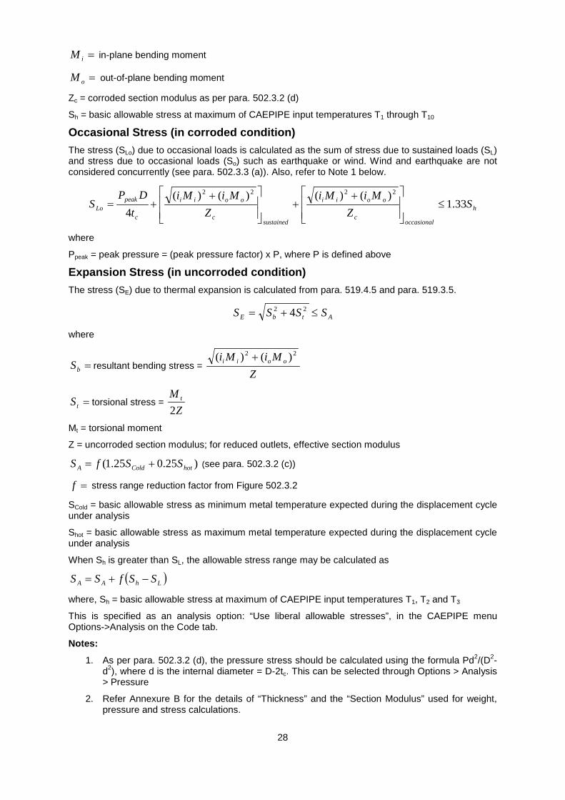
Occasional Stress (in corroded condition) The stress (SLo) due to occasional loads is calculated as the sum of stress due to sustained loads (SL) and stress due to occasional loads (So) such as earthquake or wind. Wind and earthquake are not considered concurrently (see para. 502.3.3 (a)). Also, refer to Note 1 below.
h
occasionalc
ooii
sustainedc
ooii
c
peakLo S
ZMiMi
ZMiMi
tDP
S 33.1)()()()(
4
2222
≤
++
++=
where
Ppeak = peak pressure = (peak pressure factor) x P, where P is defined above
Expansion Stress (in uncorroded condition) The stress (SE) due to thermal expansion is calculated from para. 519.4.5 and para. 519.3.5.
AtbE SSSS ≤+= 22 4
where
=bS resultant bending stress = Z
MiMi ooii22 )()( +
=tS torsional stress = Z
M t
2
Mt = torsional moment
Z = uncorroded section modulus; for reduced outlets, effective section modulus
)25.025.1( hotColdA SSfS += (see para. 502.3.2 (c))
=f stress range reduction factor from Figure 502.3.2
SCold = basic allowable stress as minimum metal temperature expected during the displacement cycle under analysis
Shot = basic allowable stress as maximum metal temperature expected during the displacement cycle under analysis
When Sh is greater than SL, the allowable stress range may be calculated as
( )LhAA SSfSS −+=
where, Sh = basic allowable stress at maximum of CAEPIPE input temperatures T1, T2 and T3
This is specified as an analysis option: “Use liberal allowable stresses”, in the CAEPIPE menu Options->Analysis on the Code tab.
Notes:
1. As per para. 502.3.2 (d), the pressure stress should be calculated using the formula Pd2/(D2-d2), where d is the internal diameter = D-2tc. This can be selected through Options > Analysis > Pressure
2. Refer Annexure B for the details of “Thickness” and the “Section Modulus” used for weight, pressure and stress calculations.

29

30

31

32
Gas Transmission and Distribution Piping Systems ASME B31.8 (2012)
Allowable Pressure For straight pipes and bends (including closely spaced and widely spaced miter bends), the allowable pressure is calculated from para. 841.1.1.
DFTSEtP n2
=
where
P = allowable pressure
S = specified minimum yield strength from para. 817.1.3 (h) and para. 841.1.4 (a)
E = longitudinal joint factor (input as material property), obtained from Table 841.1.7-1 and para. 817.1.3 (d)
tn = nominal pipe thickness
D = nominal outside diameter
F = construction type design factor, obtained from Table 841.1.6-1
T = temperature derating factor, obtained from Table 841.1.8-1 and para. 841.1.8
Stress due to Sustained and Occasional Loads (Unrestrained Piping) The sum of longitudinal pressure stress and the bending stress due to external loads, such as weight of the pipe and contents, seismic or wind, etc. is calculated according to paras. 833.6 (a) and 833.6 (b) along with paras. 805.2.3, 833.2 (b), 833.2 (d), 833.2 (e) and 833.2 (f).
Please note, the “include axial force in stress calculations” option is turned ON by default for ANSI B31.8.
Sustained Stress SL (required to compute Expansion Stress Allowable SA): For Pipes and Long Radius Bends
Sustained
ooii
SustainednL Z
MiMiAR
tPDS
+++=
22 )()(4
For other Fittings or Components.
Sustained
tooii
SustainednfcL Z
MMiMiAR
tPDS
++++=
222
)(
)()75.0()75.0(4
Sustained + Occasional Stress SLO: For Pipes and Long Radius Bends
STZ
MiMiAR
tDPP
SSoccasional
ooii
occasionaln
peakLLo 75.0
)()(4
)( 22
≤
+++
−+=
For Fittings or Components
STZ
MMiMiAR
tDPP
SSoccasional
tooii
Occasionaln
peakfcLLo 75.0
)()75.0()75.0(4
)( 222
)( ≤
++++
−+=
where

33
P = maximum operating pressure = max (P1 through P10)
Ppeak = Peak pressure factor x P
D = nominal outside diameter
tn = nominal thickness
=ii in-plane stress intensification factor; the product ii75.0 shall not be less than 1.0
=oi out-of-plane stress intensification factor; the product oi75.0 shall not be less than 1.0
=iM in-plane bending moment
=oM out-of-plane bending moment
Mt = torsional moment
Z = uncorroded section modulus; for reduced outlets, effective section modulus
R = axial force component for external loads (other than thermal expansion and pressure)
A = corroded cross-section area (i.e., after deducting for corrosion)
S = specified minimum yield strength from para. 841.1.1(a)
T = temperature derating factor, obtained from para. 841.1.8 and Table 841.1.8-1
Note:
Young’s modulus of elasticity corresponding to the lowest operating temperature [=min (T1 through T10, Tref)] is used to form the stiffness matrix for Sustained and Occasional load calculations.
Expansion Stress (Unrestrained Piping) The stress (SE) due to thermal expansion is calculated from para.833.8.
AtbE SSSS ≤+= 22 4
where
=bS resultant bending stress = Z
MiMi ooii22 )()( +
=tS torsional stress = Z
M t
2
Mt = torsional moment
Z = uncorroded section modulus; for reduced outlets, effective section modulus
Please note, “Liberal allowable” option is always turned ON for ANSI B31.8.
])(25.1[ LhCA SSSfS −+=
=f stress range reduction factor = 6/N0.2, where N = number of equivalent full range cycles
where f <= 1.0 (from para. 833.8 (b)).
Sc = 0.33SuT at the minimum installed or operating temperature
Sh = 0.33SuT at the maximum installed or operating temperature
where
Su = specified minimum ultimate tensile strength = 1.5 Sy (assumed), and
Sy = specified minimum yield strength as per para. 841.1.1(a)
T = temperature derating factor, obtained from para. 841.1.8 and Table 841.1.8-1

34
Note:
Young’s modulus of elasticity corresponding to the lowest operating temperature [=min(T1 through T10,Tref)] is used to form the stiffness matrix for Expansion load calculations.
Stress due to Sustained, Thermal and Occasional Loads (Restrained Piping) The Net longitudinal stress (SL) due to sustained, thermal expansion and occasional loads for restrained piping is calculated from paras. 833.3 (a), 833.3 (b) along with paras. 805.2.3, 833.2 (a), 833.2 (c), 833.2 (d), 833.2 (e) and 833.2 (f)
STSS
SSSSSS
SSSSSSS
coldestTwarmestT
OccasionalBxpBxp
sustainedBxpBxpL
9.0),max(
),max(
),max(
≤
+−+++
+−+++=
where
Internal pressure stress = n
p tPDS2
3.0=
Stress due to axial loading (other than thermal expansion and pressure) = ARS X = , and may be positive
or negative Nominal bending stress SB from Weight and / or other External loads for
For Pipes and Long Radius Bends
ZMiMi
S ooiiB
22 )()( +=
For other Fittings or Components.
ZMMiMi
S tooiiB
222 )()75.0()75.0( ++=
Thermal expansion stress = )( oiT TTES −= α , and may be positive or negative
Where
P = maximum operating pressure = max(P1 through P10)
D = nominal outside diameter
tn = nominal thickness
=ii in-plane stress intensification factor; the product ii75.0 shall not be less than 1.0
=oi out-of-plane stress intensification factor; the product oi75.0 shall not be less than 1.0
=iM in-plane bending moment
=oM out-of-plane bending moment
Mt = torsional moment
R = axial force component for external loads (other than thermal expansion and pressure)
A = corroded cross-sectional area (i.e., after deducting for corrosion)
Z = uncorroded section modulus; for reduced outlets, effective section modulus
S = Specified Minimum Yield Strength (SMYS) from para. 841.1.1 (a)
T = Temperature derating factor from para. 841.1.8 and Table 841.1.8-1
E = Young’s modulus at ambient (reference) temperature
35
Ti = installation temperature = Tref in CAEPIPE
To = warmest or coldest operating temperature
=α coefficient of thermal expansion at To defined above
36

37

38
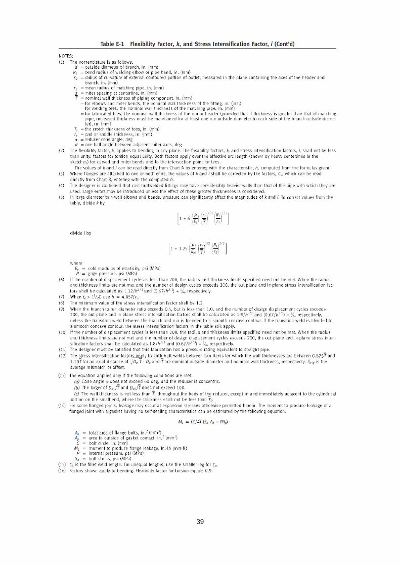
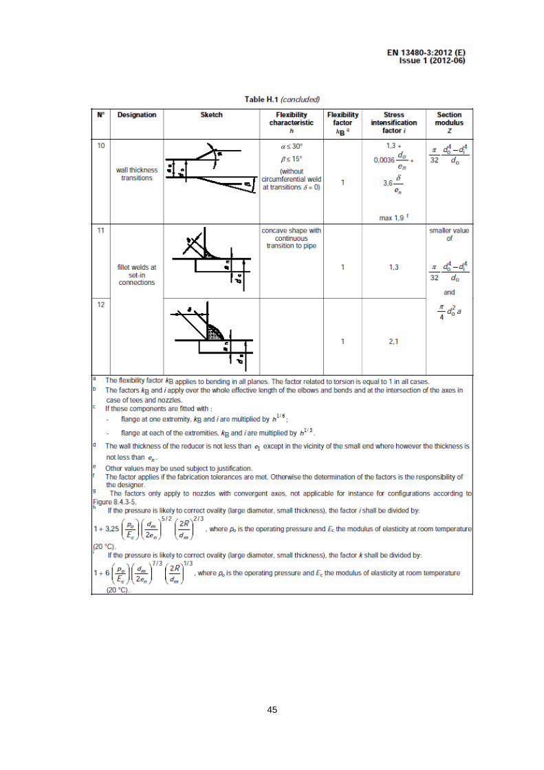
39

40
EN 13480 (2012) Allowable Pressure The allowable pressure for straight pipes is calculated from equation 6.1-1 or 6.1-3 depending on the ratio between inner and outer diameter.
For 7.1/ ≤io DD
eDfzeP
o −=
2
For 7.1/ >io DD
)1()1(
2
2
aafzP
+−
=
where
P = allowable pressure
f = allowable stress
z = joint factor (input as material property in CAEPIPE)
e = nominal pipe thickness x [1 - mill tolerance %/100] - corrosion allowance “c”
(Any additional thickness required for threading, grooving, erosion, corrosion, etc. should be included in corrosion allowance in CAEPIPE)
Do = outside diameter
Di = inside diameter
oDea 21−=
For pipe bends the maximum allowable pressure is calculated using the equivalent pipe wall thickness eequi.
fequi t
ee =
Where
)50.0/()25.0/(
−−
=DRDRt f
R = radius of bend
For closely spaced miter bends, the allowable pressure is calculated from equations 6.3.4-1 and 6.3.4-2.
−−
+=
)2/()(,
)tan643.0(min
2
rRrrRfze
reerfzeP
s
s
θ with θ ≤ 22.5
For widely spaced miter bends, the allowable pressure is calculated from equations 6.3.4-1, 6.3.4-2 and 6.3.5-1
−−
+=
)2/()(,
)tan643.0(min
2
rRrrRfze
reerfzeP
s
s
θ with θ ≤ 22.5

41
)tan25.1(
2
reerfzeP
θ+= with θ > 22.5
Where
r = mean radius of pipe = (D - t)/2
Rs = effective bend radius of the miter
θ = miter half angle
Sustained Stress The stress ( 1σ ) due to sustained loads (pressure, weight and other sustained mechanical loads) is calculated from equation (12.3.2-1)
fA
n
o fZiM
ePD
≤+=75.0
41σ
where
P = maximum of CAEPIPE input pressures P1, P2 and P3
Do = outside diameter
en = nominal pipe thickness
=i stress intensification factor; the product of 0.75i shall not be less than 1.0
=AM resulting bending moment due to sustained loads
Z = uncorroded section modulus; for reduced outlets / branch connections, effective section modulus
ff = design (allowable) stress for flexibility analysis at the operating temperature under consideration (i.e., at Ti where i = 1 to 10)
Sustained plus Occasional Stress The stress ( 2σ ) due to sustained and occasional loads is calculated from equation (12.3.3-1) as the sum of stress due to sustained loads such as due to pressure, weight and other sustained mechanical loads and stress due to occasional loads such as earthquake or wind. Wind and earthquake are not considered concurrently.
fBA
n
o kfZiM
ZiM
ePD
≤++=75.075.0
42σ
MB=resultant bending moment due to occasional load
k = 1.2 if the occasional load is acting less than 1% in any 24 hour operating period. In CAEPIPE k = 1.2 is used for occasional loading by default.
User can modify this value through CAEPIPE menu Options > Analysis > Code > Occasional load factor.
Expansion Stress The stress ( 3σ ) due to thermal expansion is calculated from equation (12.3.4-1)
aC f
ZiM
≤=3σ
where
MC = resultant moment due to thermal expansion and alternating loads
Z = uncorroded section modulus; for reduced outlets / branch connections, effective section modulus

42
c
hhCa E
EffUf )25.025.1( +=
=U cyclic stress range reduction factor taken from table 12.1.3-1
fC = basic allowable stress at minimum metal temperature consistent with the loading under consideration
fh = basic allowable stress at maximum metal temperature consistent with the loading under consideration
Ec = modulus of elasticity at the minimum metal temperature consistent with the loading under consideration
Eh = modulus of elasticity at the maximum metal temperature consistent with the loading under consideration
If the above condition in equation (12.3.4-1) is not met, equation (12.3.4-2) may be used.
afCA
n
o ffZ
iMZiM
ePD
+≤++=75.0
44σ
Additional Conditions for the Creep Range For piping operating within the creep range, the stress, 5σ , due to sustained, thermal and alternating loadings shall satisfy the equation (12.3.5-1) below.
crCAo f
ZiM
ZiM
ePD
≤++=3
75.075.045σ
where
crf = allowable creep stress value

43

44
45

46

47

48

49
ANSI/API Standard 610 Tenth Edition, October 2004 ISO 13709: 2003, (Identical) Centrifugal pumps for petroleum, petrochemical and natural gas industries

50
API Standard 610 / ISO 13709
API 610 (Tenth Edition, 2004) / ISO 13709 for Pumps The allowable nozzle forces and moments for pumps are taken from Table 4 of the tenth edition of API Standard 610 / ISO 13709.

51
API Standard 610 / ISO 13709
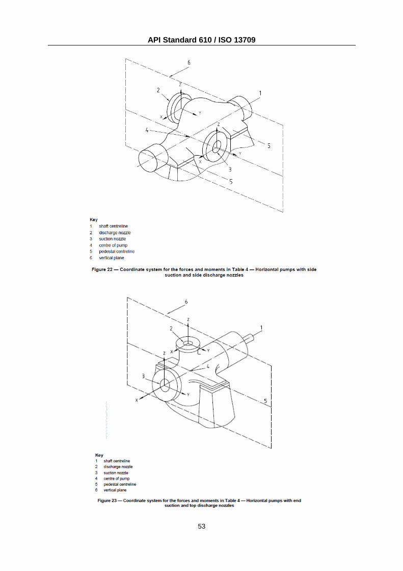
The coordinate systems and nozzle orientations for various pump configurations are shown next.

52
API Standard 610 / ISO 13709
53
API Standard 610 / ISO 13709

54
API Standard 610 / ISO 13709

55
API Standard 610 / ISO 13709
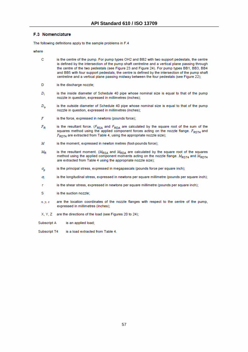
Criteria for Piping Design The criteria for piping design are taken from Appendix F of the API 610.

56
API Standard 610 / ISO 13709
57
API Standard 610 / ISO 13709
58
Annexure B
Weld Strength Reduction Factors built into CAEPIPE (as given in Table 102.4.7 of ASME B31.1 – 2012)

59
Weld Strength Reduction Factors applied for calculating the Allowable Design Pressure of components (extracted from Table 102.4.7 of ASME B31.1-2012).
Sl. No. Steel Group
Weld Strength Reduction Factor for Temperature, Deg F (Deg C)
700 750 800 850 900 950 1000 1050 1100 1150 1200
(371) (399) (427) (454) (482) (510) (538) (566) (593) (621) (649)
1 Carbon Steel (CS) with Max. Temp in CAEPIPE is <= 800 [see note 1 below]
1.00 0.95 0.91 NP NP NP NP NP NP NP NP
2 Carbon Steel (CS) with Max. Temp in CAEPIPE > 800
- - 1.00 0.95 0.91 0.86 0.82 0.77 0.73 0.68 0.64
3 Ferritic Steels (FS)
1.00 1.00 1.00 1.00 1.00 1.00 0.95 0.91 0.86 0.82 0.77
4 Austenitic Steel (AS) [contd. in note 2 below]
1.00 1.00 1.00 1.00 1.00 1.00 0.95 0.91 0.86 0.82 0.77
5 Materials other than those stated from Sl. Nos. 1 to 4
1.00 1.00 1.00 1.00 1.00 1.00 1.00 1.00 1.00 1.00 1.00
Notes:
1. NP = Not permitted
2. For Austenitic Steels (including 800H and 800 HT) the values upto 1500 deg F are as follows:
Temperature, deg F Temperature, deg C Weld Strength Reduction Factor
1250 677 0.73
1300 704 0.68
1350 732 0.64
1400 760 0.59
1450 788 0.55
1500 816 0.50

60
Annexure C
Thickness and Section Modulus used in Weight, Pressure and Stress Calculations for ASME B31.x Codes

61
Particulars Allowable Pressure Pipe Weight Sustained Stress Expansion Stress Occasional Stress B31.1 (2012) Pipe Thickness used
Nominal Thk. x (1-mill tolerance/100) – Corrosion allowance
Nominal Thickness Nominal Thickness - Nominal Thickness
Section Modulus used - -
Uncorroded Section Modulus; For Branch, effective section modulus
Uncorroded Section Modulus; For Branch, effective section modulus
Uncorroded Section Modulus; For Branch, effective section modulus
B31.3 (2012) Pipe Thickness used
Nominal Thk. x (1-mill tolerance/100) – Corrosion allowance
Nominal Thickness Nominal Thickness - Corrosion allowance - Nominal Thickness –
Corrosion allowance
Section Modulus used - -
Corroded Section Modulus; For Branch, effective section modulus
Uncorroded Section Modulus; For Branch, effective section modulus
Corroded Section Modulus; For Branch, effective section modulus
B31.4 (2012) Pipe Thickness used
Nominal Thk. x (1-mill tolerance/100) – Corrosion allowance
Nominal Thickness Nominal Thickness - Nominal Thickness
Section Modulus used - -
Uncorroded Section Modulus; For Branch, effective section modulus
Uncorroded Section Modulus; For Branch, effective section modulus
Uncorroded Section Modulus; For Branch effective section modulus
B31.5 (2013)
Pipe Thickness used
Nominal Thk. x (1-mill tolerance/100) – Corrosion allowance
Nominal Thickness Nominal Thickness – Corrosion allowance - Nominal Thickness –
Corrosion allowance
Section Modulus used - -
Corroded Section Modulus; For Branch, effective section modulus
Uncorroded Section Modulus; For Branch, effective section modulus
Corroded Section Modulus; For Branch, effective section modulus

62
Particulars Allowable Pressure Pipe Weight Sustained Stress Expansion Stress Occasional Stress B31.8 (2012) Pipe Thickness used
Nominal Thk. Nominal Thickness Nominal Thickness - Nominal Thickness
Section Modulus used - -
Uncorroded Section Modulus; For Branch, effective section modulus
Uncorroded Section Modulus; For Branch, effective section modulus
Uncorroded Section Modulus; For Branch, effective section modulus
B31.9 (2008) Pipe Thickness used
Nominal Thk. x (1-mill tolerance/100) – Corrosion allowance
Nominal Thickness Nominal Thickness - Nominal Thickness
Section Modulus used - -
Uncorroded Section Modulus; For Branch, effective section modulus
Uncorroded Section Modulus; For Branch, effective section modulus
Uncorroded Section Modulus; For Branch, effective section modulus
Note: 1. Corrosion allowance includes thickness required for threading, grooving, erosion, corrosion etc. 2. Uncorroded section modulus = section modulus calculated using the nominal thickness. 3. Corroded section modulus = section modulus calculated using the “corroded thickness” corroded thickness = nominal thickness – corrosion allowance 4. Effective section modulus = section modulus calculated using effective branch thickness, which is lesser of iitb or th where, tb = branch nominal thickness, th = header nominal thickness, ii = in-plane SIF at branch