reading, understanding, and using construction plans€¦ · reading, understanding, and using...
TRANSCRIPT
Reading, Understanding, and Using Construction Plans
Delaware T2/LTAP Center

Delaware T2 Center
• T2 Centers or LTAPs located in all 50 states
• Funded by FHWA and state DOTs
• Mission – promote training, tech transfer, research implementation at local level
• Delaware T2 hosted by University of Delaware, part of Delaware Center for Transportation
• Delaware T2 funded by FHWA and DelDOT

• Delaware Center for Transportation– T2/LTAP Center
– Based at University of Delaware
– Dr. Christopher Meehan – Director, DCT
– Dr. Earl “Rusty” Lee – T2/LTAP Program Coordinator
• Matheu J. Carter, P.E.– T2 Engineer
– Municipal Engineering Circuit Rider
Municipal Circuit Rider Program

The Preliminaries
Today’s Instructor:
• Matheu J. Carter, P.E. – Municipal Engineering Circuit Rider
Restrooms, smoking, parking, etc.
Standard Reminders:
• Cell phones, pagers, beepers, walkie-talkies
• Sidebar conversations

More Preliminaries
• Questions – any time
• We’re a small crowd – let’s keep it interactive and informal
• Sharing of thoughts or examples – any time
• These slides will be posted on our website – see link on your notes

• Click here to take our 1 minute questionnaire and be sure– https://delaware.ca1.qualtrics.com/jfe/form/SV_3fyvj
3k8Z4IIzZj
• Ensures you get our:– Newsletters– Urgent technical briefs– Upcoming training workshop notifications
• Don’t risk it! Do it today.
Are you on our mailing list?

Construction Plans
• Public versus private project
– Public
• Probably just one of several sets of documents known collectively as the Contract Documents
– Private
• Can sometimes be a standalone document
• Small versus large project
– Smaller projects may have substantially fewer and more basic Contract Documents

Contract Documents
• Collectively, these tell the Contractor
– What it must construct
– What it can and cannot use
– Methods it can, must, or cannot use
– Time limits, how it gets paid, etc.
• Collectively, these tell the Owner
– What its authority is
– How and when it can intervene

Contract Documents
Typical DOT Standard Specification language• Each individual Contract Document is an essential part of the
Contract and a requirement occurring in one is binding as though occurring in all. All of the Contract Documents are intended to be complementary and to describe and provide for a complete Contract.
• [BUT,] In the case of a discrepancy between the Contract Documents the governing ranking will be:– A. General Description– B. General Notices– C. Plans– D. Special Provisions– E. Standard Construction Details– F. Standard Specifications
Source: DelDOT, “Standard Specifications for Road and Bridge Construction,” 105.06, August 2016
This is the so-called “hierarchy of documents”

Documents During Construction
Many other documents generated during construction
• Shop drawings (working drawings)
• Testing results (QA/QC)
• RFIs (Requests for Information)
• Change orders
• Schedules
• Correspondence
• Reports (geotechnical, environmental, etc.)

“Typical” Organization
• Lots of styles, arrangements, formats
• A “typical” arrangement from DelDOT– Title, Index, Legend, Notes, and Earthwork
– Typical Sections
– Horizontal and Vertical Control
– Construction Plans
– Profiles
– Grades and Geometrics
– Pavement Joint Plans

“Typical” Organization
• A “typical” arrangement from DelDOT (cont’d)
– Borrow Site Grading Plans, Laydown Area, and Borrow Site Notes
– Construction Details
– Bridge Plans and Details
– Retaining Wall Plans and Details
– Maintenance of Stream Flow
– Stormwater Management

“Typical” Organization
• A “typical” arrangement from DelDOT (cont’d)
– Environmental Compliance
– Traffic Control Notes & Phasing, MOT & E&S
– Detour Plans
– Lighting
– Signing, Striping, Conduit & Signal Plans
– Right-Of-Way Plans
• We’ll look at some of these

“Typical” Organization
• As we look at some of these drawings…
• …think about what role you might be in and which drawings would be of most use to you
• Inspector
• Testing Technician
• Surveyor
• Shop Drawing Reviewer
• Public Relations
• ROW Specialist
• Bridge Forman
• Pipe Forman
• Bidder
• Precaster

Title Sheet

Plan Sheet Index

Legend Sheet

General Notes

General Notes

Some More Interesting Notes
33. THE LOCATION FOR ITEM 759506 - FIELD OFFICE, TYPE II.22 SPECIAL COMPLEX SHALL BE ON THE DELDOT OWNED PARCEL EAST OFUS 13 AT APPROXIMATE SR 1 STATION 1832+00. SEE DRAWING GR-02.

Earthwork Quantities
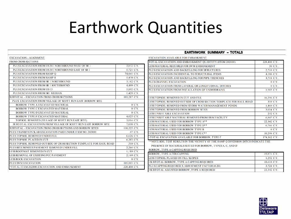
Earthwork Quantities

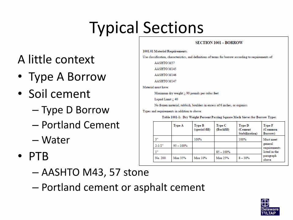
Typical Sections

Typical Sections
Typical Sections
A little context
• Type A Borrow
• Soil cement– Type D Borrow
– Portland Cement
– Water
• PTB– AASHTO M43, 57 stone
– Portland cement or asphalt cement

Typical Sections
AASHTO M43, 57 stone

Horizontal and Vertical Control

Horizontal and Vertical Control

Horizontal and Vertical Control

Construction Plans

Construction Plans

Construction Plans

Construction Plans

Construction Plans
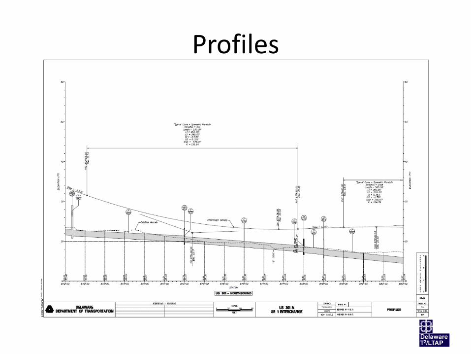
Profiles

Grades and Geometrics

Construction Details

Bridge PlansBridge 1-433
Pier 1The first of
two “straddle bents”
Nominal weight: 8’-7” x 9’-6” x 116’-6” = 9,499.6 CF x 150 #/CF = 1.4 million pounds = 712 ton

Bridge PlansBridge 1-433
Pier 2A
conventional pier

Bridge PlansBridge 1-433
Pier 3The second
“straddle bent”

Stormwater Plans

Stormwater Plans
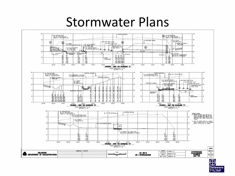
Stormwater Plans

Stormwater PlansThis is SW 401
from the profile sheet
we just saw…but I don’t see it labeled as
such

Traffic Control Plans
• Very detailed plans
• Lots and lots of notes
• Signs and pavement markings shown overtop of construction plans
• Traffic phasing

Detour Plan

Signing, Striping, … Plans

Right of Way

Right of Way

Right of Way

Right of Way
How We Use the Plans
• We’ll use a box culvert example to illustrate how we use various parts of the Contract Drawings and the Working Drawings (shop drawings).

Box Culvert Example
Box Culvert
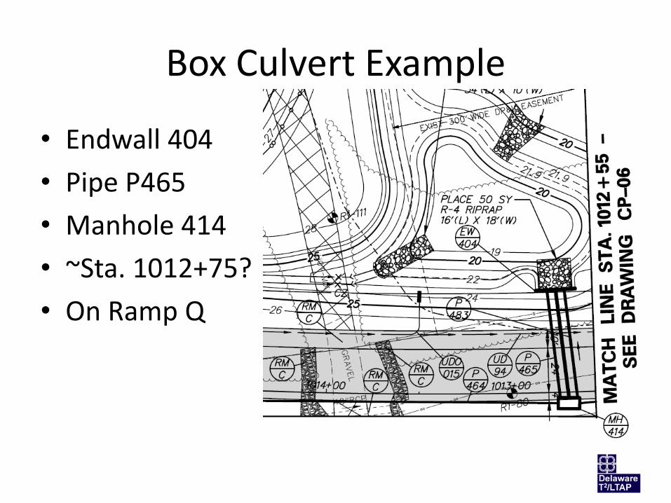
Box Culvert Example
• Endwall 404
• Pipe P465
• Manhole 414
• ~Sta. 1012+75?
• On Ramp Q

Box Culvert Example
• Endwall 404
• Pipe P465
• Manhole 414
• What’s this?
– Special Detail?
– Sheet DT-14?
– That’s on the Construction Details

Box Culvert Example
Box Culvert

Box Culvert Example
• More like Sta. 1012+40?
• Existing and proposed grades
• Soil boring close by – Sta. 1012+36.48

Box Culvert Example
DT-14
Endwall 404…We’ve been looking for you

Box Culvert Example
• 3’-2” x 22’ footer
– 1’-3” thick/deep
• Twin boxes
– 2’ H x 4’ W
– Skewed 87º58’19”

Box Culvert Example
• 12” GAB
• Some rebar detail

Box Culvert Example
DT-16
MH 414…There you are
Box Culvert Example
• Let’s compare the Contract Drawings to the Shop Drawings
– Shared culpability? Gillespie Precast submits to Tutor Perini submits to WRA submits to RK&K
• Who sealed it?
– Level of detail in shop drawing versus plans

Box Culvert Example
• Think of shop drawings like this
– Contractor (subcontractor, precaster, vendor)
• We looked at your plans and specifications and this is what we plan to deliver to you; we assert that it is compliant with your requirements
– Owner (Owner’s representative)
• Agreed
• Once this exchange is complete, the shop drawing becomes the standard for acceptance
Questions?
Matheu J. Carter, P.E.
Delaware Center for Transportation
Delaware T2/LTAP Center
355 DuPont Hall
University of Delaware