read instructions carefully: read and follow all instructions
TRANSCRIPT

WARNING: Improper installation, adjustment, alteration, service or maintenance can cause property damage, injury, or death. Read the installation, operating and maintenance instructions thoroughly before installing or servicing this equipment.
— WHATTODOIFYOUSMELLGAS
• OpenWindows • DO NOTtrytolightanyappliance. • DO NOTuseelectricalswitches. • DO NOTtouchanyelectricalswitch;donotuseanyphoneinyourbuilding.
• Immediatelycallyourlocalgassupplier;followthegassupplier’sinstructions. (Installationandservicemustbeperformedbyaqualifiedinstaller,serviceagencyorthegassupplier.) • Ifyoucannotreachyourgassupplier,calltheFireDepartment.
FOR YOUR SAFETY: -This heater is intended to be used as a gas fired radiant heater for the heating of poultry and swine confinement buildings. If you are considering using this product for any application other than its intended use, then please contact Heatstar, Inc
- Donotstoreorusegasolineorotherflammablevaporsandliquidsinthevicinityofthisoranyotherappliance.
WARNING: Iftheinformationintheseinstructionsisnotfollowedexactly,afireorexplosionmayresultcausingpropertydamage,personalinjuryorlossoflife.
18683Heatstar,IncGroup,Inc.,4560W.160THST.,CLEVELAND,OHIO44135•866-447-2194
OPERATING INSTRUCTIONS AND OWNER’S MANUAL
R E A D I N S T R U C T I O N S C A R E F U L L Y : Re a d a n d f o l l ow a l l i n s t r u c t i o n s .P l ac e i n s t r u c t i o n s i n a s a fe p l ac e fo r f u t u re re fe ren c e . Do not a l l ow any -one who has not read these instructions to assemble, light, adjust or operate the heater.
Model#
by ENERCO
LANGUAGES INCLUDEDJET SERIESPoultry & Swine Confinement Buildings Agricultural Buildings
•ENGLISH•SPANISH
JET20JET25
2Enerco | Heatstar AG Series Heater Operating Instructions and Owner’s Manual
WARNING: FIRE,BURN,INHALATION,ANDEXPLOSIONHAZARD.KEEPSOLIDCOMBUSTIBLESSUCHASBUILDINGMATERIALS,PAPERORCARDBOARDASAFEDISTANCEAWAYFROMTHEHEATERASRECOMMENDEDBYTHEINSTRUCTIONS.NEVERUSETHEHEATERINSPACESWHICHDOORMAYCONTAINVOLATILEORAIRBORNECOMBUSTIBLES,ORPRODUCTSSUCHASGASOLINE,SOLVENTS,PAINTTHINNER,DUSTPARTICLESORUNKNOWNCHEMICALS.
GENERAL HAZARD WARNING:FAILURETOCOMPLYWITHTHEPRECAUTIONSANDINSTRUCTIONSPROVIDEDWITHTHISHEATERCANRESULTINDEATH,SERIOUSBODILYINJURYANDPROPERTYLOSSORDAMAGEFROMHAZARDSOFFIRE,EXPLOSION,BURN,ASPHYXIATION,CARBONMONOXIDEPOISONING,AND/ORELECTRICALSHOCK.ONLYPERSONSWHOCANUNDERSTANDANDFOLLOWTHEINSTRUCTIONSSHOULDUSEORSERVICETHISHEATER.IFYOUNEEDASSISTANCEORHEATERINFORMATIONSUCHASANINSTRUCTIONSMANUAL,LABELS,ETC.,CONTACTTHEMANUFACTURER.
WARNING:YOURSAFETYISIMPORTANTTOYOUANDTOOTHERS,SOPLEASEREADTHESEINSTRUCTIONSBEFOREYOUOPERATETHISHEATER.
CONTENTS
SECTION1INTRODUCTION...................................2
SECTION2PLANNING...........................................3
SECTION3INSTALLATION&ASSEMBLY.................5
SECTION4ENGINEERINGSPECIFICATIONS............9
SECTION5AIRINTAKE/VENTING........................9
SECTION6GASPIPING........................................ 11
SECTION7WIRING.............................................. 11
SECTION8OPERATIONMAINTENANCE............... 13
SECTION9TROUBLESHOOTING........................... 13
ACCESSORYPARTS.............................................. 14
SECTION10REPLACEMENTPARTS....................... 15
WARRANTYINFORMATION.................................20
WARNING: THIS PRODUCT CAN EXPOSE YOU TO CHEMICALS
INCLUDING LEAD AND LEAD COMPOUNDS, WHICH ARE KNOWN TO THE STATE OF CALIFORNIA TO CAUSE CANCER AND BIRTH DEFECTS OR OTHER
REPRODUCTIVE HARM. FOR MORE INFORMATION VISIT WWW.P65WARNINGS.CA.GOV
SECTION 1:Introduction JETmodelsarelow-cost,fieldassembledinfraredheatersthatareeasytoinstallandrequireonlyminimalmaintenance.Theyaredesignedtoprovideyearsofeconomicaloperationandtrouble-freeservice.
Checking ShipmentChecktheshipmentagainsttheBillofLadingforshortages.Also,checkforexternaldamagetocartons.Noteanyshortages,and/orexternaldamagetocartonsontheBillofLadinginthepresenceofthedeliverytrucker.Thedeliverytruckershouldacknowledgeanyshortagesordamagebyinitializingthis“noted”BillofLading.Immediatelyreportanyclaimsfordamagedmaterial,orshortagesthatwerenotevidentatthetimeofshipment,tothecarrierandyourHeatstar,IncFactoryRepresentative.
Installer ResponsibilityAllheatersandassociatedgaspipingshouldbeinstalledinaccordancewithapplicablespecificationsandthisinstallationmadeonlybyfirms(orindividuals)wellqualifiedinthistypeofwork.Consultlocalbuildinginspectors,FireMarshalsoryourlocalHeatstar,IncFactoryRepresentativeforguidance.
JETheatersareinstalledonthebasisofinformationgiveninalayoutdrawing,whichtogetherwiththecitedcodesandregulations,comprisethebasicinformationneededtocompletetheinstallation.Theinstallermustfurnishallneededmaterialthatisnotfurnishedasstandardequipment,anditishisresponsibilitytoseethatsuchmaterials,aswellastheinstallationmethodsheusesresultinajobthatisworkmanlikeandincompliancewithallapplicablecodes.
Heatstar,IncFactoryRepresentativeshavehadtrainingandexperienceintheapplicationofthisequipmentandcanbecalledonforsuggestionsaboutinstallationwhichcansavematerialandcost.

3 Operating Instructions and Owner’s ManualEnerco | Heatstar AG Series Heater
SECTION 2: PlanningThefollowingcodesandinstructionsshouldbefollowedwhenplanningtheinstallationofthisJETheater.Inadditiontotheseinstructions,thewarningsmustbecarefullyadheredtosinceimproperinstallationmayleadtopropertydamage,injury,ordeath.
National Standards and Applicable Codes
Gas Codes:
•Thetypeofgasappearingonthenameplatemustbethetypeofgasused.Installationmustcomplywithlocalcodesandrecommendationsofthelocalgascompany,andtheNationalFuelGasCode,ANSIZ223.1–latestrevision,(sameasNFPABulletin54)(theNaturalGasandPropaneInstallationCode,CSAB149.1)Canadaonly.
•Clearancebetweentheheateranditsventandadjacentcombustiblematerial(whichispartofthebuildingoritscontents)shallbemaintainedtoconformwiththeStandardforInstallationofGasAppliancesandGasPiping,NFPA-54/ANSIZ223.1–latestrevision,NationalFuelGasCode(theNaturalGasandPropaneInstallationCode,CSAB149.1)Canadaonly.
Hazardous Locations:Wherethereisthepossibilityofexposuretocombustibleairbornematerialorvapor,consultthelocalFireMarshal,thefireinsurancecarrierorotherauthoritiesforapprovaloftheproposedinstallation.
Critical Considerations
ThisJETmodelisasuspendedheater.Therefore,itsstability,flexibility,andsafetyareveryimportant.Beforestartinginstallation,besurethesystemcanmeetthefollowingrequirements.
•Maintainspecifiedclearancestocombustibles,andsafedistancefromtheheat-sensitivematerial,equipmentandworkstations.
•Thestatedclearancestocombustiblesrepresentasurfacetemperatureof90°F(30°C)aboveroomtemperature.Buildingmaterialswithlowheattolerance(suchasplastic,vinylsiding,canvas,etc.)maybesubjecttodegradationatlowertemperatures.Itistheinstallersresponsibilitytoassurethatadjacentmaterialsareprotectedfromdegradation.
•Provideaccesstoburnersforservicing,preferableonbothsides,aboveandbehindtheburnerforremoval.
•Alwaysobserveminimumclearancestocombustibleslocatedonpage4.
•Planlocationsupports(seeFigure2A-Bstartingonpage6).
•Theinstallationmustconformwithlocalbuildingcodesorintheabsenceoflocalcodes,withtheNationalFuelGasCode,ANSIZ223.1/NFPA54(theNaturalGasandPropaneInstallationCode,CSAB149.1)Canadaonly.
•Ifanexternalelectricalsourceisutilized,theheater,wheninstalled,mustbeelectricallygroundedinaccordancewiththeNationalElectricalCode,ANSI/NFPA70orcurrentCanadianElectricalCode,CSAC22.1.
Installation ProcedureTakemaximumadvantageofthebuildingupperstructure,beams,joists,purlins,etc.,fromwhichtosuspendtheheater.Thereisnouniquesequenceforinstallationofthetubing.On-siteobservationwillusuallyrevealalogicalsequence.Begintheinstallationatthemostcriticaldimension.Reflectorsandtubingcanbeinstalledasyoumovealong.Carefullyadjustsystempitchateachpositiontoleveltheheater.Pitchdownone-halfinchin20feet(awayfromburner).
DON’TPressuretestthegaslineusinghighpressure(greaterthan½PSIG)withoutclosingthehigh-pressureshutoffcocks.Failuretodosowillresultindamagetotheburners.
DO Familiarizeyourselfwithlocalandnationalcodes.
Developaplannedprocedurewhichwillconservematerialandlaboronthejob.
Checktoseethatallmaterialandequipmentisonthejobbeforestartinginstallation.
Allowforthermalexpansionofthetubes.
Installthegasconnectoronlyasshownininstructions(seeFigure14&15onpage11).
Useselftappingscrewswherereflectorsoverlaptoassurethattheydon'tcomeapart.
Attachreflectorretentionwiretoburnerboxorchainsuspendingburnerbox.Thewirecomesattachedtooneofthereflectors.Seeintructionsintubesetfordetails.
Provide1sq.inchoffreeairopeningtoeach1,000BTU/hr.ofheaterinput(butnotlessthan100sq.inches)inenclosedspaces.Oneopeningshouldbewithin12inchesofthetopandonewithin12inchesofthebottomoftheenclosure.
4Enerco | Heatstar AG Series Heater Operating Instructions and Owner’s Manual
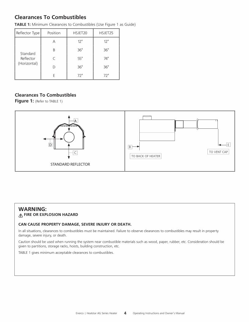
Clearances To CombustiblesFigure 1: (RefertoTABLE1)
STANDARD REFLECTOR
D
A
C
EB
TO VENT CAPTO BACK OF HEATER
WARNING: FIRE OR EXPLOSION HAZARD
CAN CAUSE PROPERTY DAMAGE, SEVERE INJURY OR DEATH.
Inallsituations,clearancestocombustiblesmustbemaintained.Failuretoobserveclearancestocombustiblesmayresultinpropertydamage,severeinjury,ordeath.
Cautionshouldbeusedwhenrunningthesystemnearcombustiblematerialssuchaswood,paper,rubber,etc.Considerationshouldbegiventopartitions,storageracks,hoists,buildingconstruction,etc.
TABLE1givesminimumacceptableclearancestocombustibles.
Clearances To CombustiblesTABLE 1:MinimumClearancestoCombustibles(UseFigure1asGuide)
ReflectorType Position HSJET20 HSJET25
StandardReflector
(Horizontal)
A 12" 12"
B 36" 36"
C 55" 74"
D 36" 36"
E 72" 72"

5 Operating Instructions and Owner’s ManualEnerco | Heatstar AG Series Heater
SECTION 3: Installation & Assembly
TUBECOUPLING(14612)*USEDONJET25*
KEYFORTUBECOUPLING(14616)*USEDONJET25*
TUBEHANGER-3"Tube=14572-3.5"Tube=14573-4"Tube=14585P
JET20•10'-3"ODAluminized(06454)•10'-3.5ODSteel(06457)
JET20-TURBULATORBAFFLE7'(03444)JET25-TURBULATORBAFFLE10'(03445)
REFLECTOR-5'=00417A*JET25ONLY* -10'=00418A-10'w/Wire=00422
BURNERBOX
JET25
•10'-3.5"ODAluminized(06455)
•10'-4"ODSteel(06456)
•5'-4"ODSteel(06453)*NOFLANGE*
HEATEXCHANGERTUBE
VENTCAP(19041)VENTADAPTER(14582)
6Enerco | Heatstar AG Series Heater Operating Instructions and Owner’s Manual
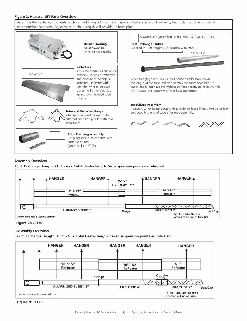
Assembly Overview
20 ft. Exchanger length. 21 ft. - 4 in. Total Heater length. Six suspension points as indicated.
HANGER HANGER HANGER HANGER
10’ 2-1/2”Reflector
HRS TUBE 3.5”
2-1/2” OVERLAY TYP
(1) 7’ Turbulator SectionLocated at the End of Tube Set
ALUMINIZED TUBE 3” Vent CapFlange
10’ 2-1/2”Reflector
Arrow Indicates Suspension Point
Assembly Overview
25 ft. Exchanger length. 26 ft. - 4 in. Total Heater length. Seven suspension points as indicated
10’ 2-1/2”Reflector
(1) 10’ Turbulator SectionLocated at End of Tube
HANGER HANGER HANGER HANGER
ALUMINIZED TUBE 3.5” HRS TUBE 4”
Flange
HRS TUBE 4”
HANGER
Vent Cap
Coupler
10’ 2-1/2”Reflector
5’ 2”Reflector
Arrow Indicates Suspension Point
Burner HousingMustalwaysbeinstalledhorizontally.
Turbulator AssemblyHeatstarAGJetheatersshipwithturbulatorslooseinbox.Turbulatoristobeplacedintoendoftubeaftertubeassembly.
ReflectorsAlternateoverlapasshownonoverview.Lengthofreflectorandamountofoverlapisindicated.Reflectorwithretentionwiretobeusedclosesttoburnerbox.Seeinstructionsincludedwithtubeset
10'2-1/2"
Tube Coupling AssemblyCouplingshouldbeorientedwithslidebarontop.(OnlyusedonJET25)
AssembletheheatercomponentsasshowninFigures2A,2B.Installappropriatedsuspensionhardware,beamclamps,chainorrodatpredeterminedlocations.Adjustmentofchainlengthwillprovideuniformpitch.
Tube and Reflector Hanger2hangersrequiredforeachtube,differentsizedhangersfordifferentsizedtubes.
ALUMINIZED(ONLYfirst10ft.)andHOTROLLEDSTEEL
Heat Exchanger TubesSuppliedin10ft.lengths(5'includedwithJet25)
Whenhangingthetubesyouwillnoticeaweldseamdownthelengthofthetube.Whenassemblythetubestogetherisisimportanttonothavethisweldseamfacedirectlyupordown,thiswillincreasethelongevityofyourheatexchangers.
Figure 2: Heatstar JET Parts Overview
*JET25ONLY*
Figure 2A JET20
Figure 2B JET25
7 Operating Instructions and Owner’s ManualEnerco | Heatstar AG Series Heater
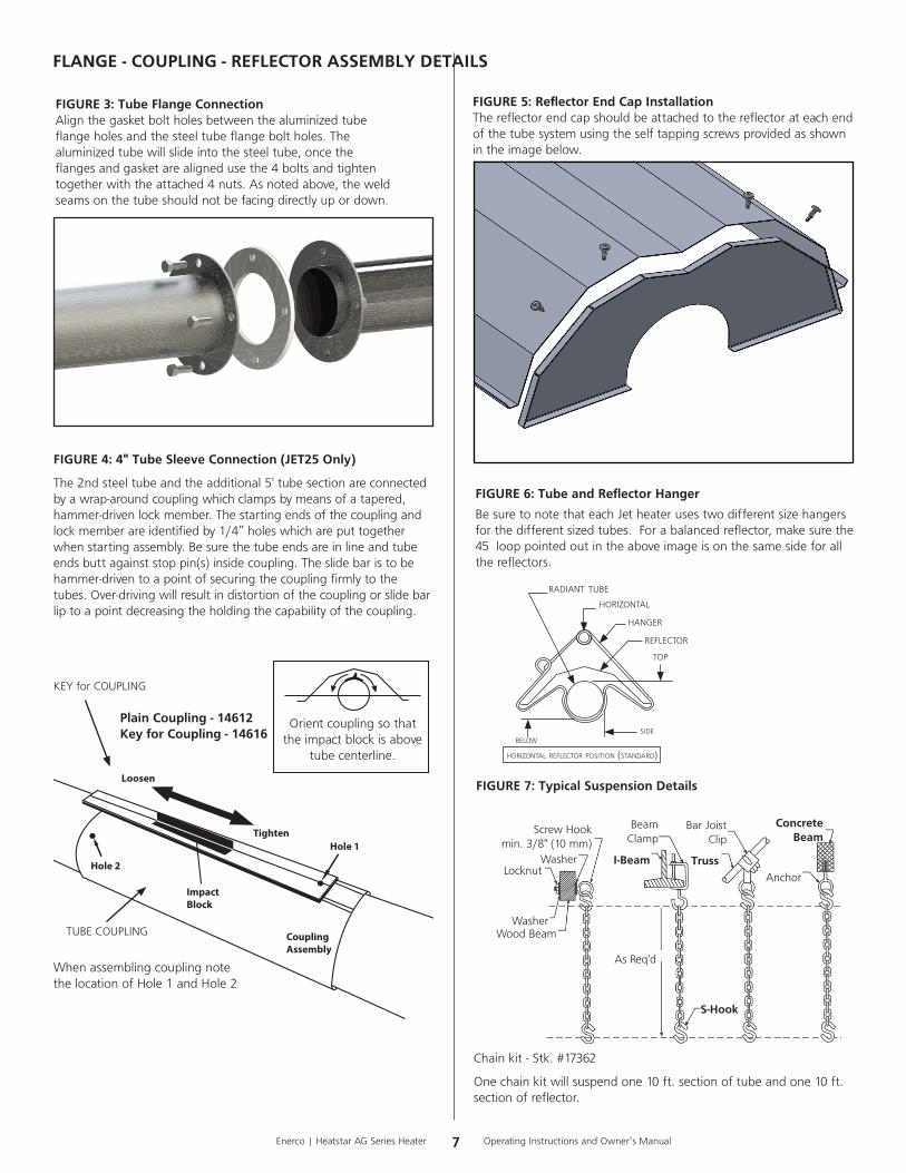
FIGURE 4: 4" Tube Sleeve Connection (JET25 Only)
The2ndsteeltubeandtheadditional5'tubesectionareconnectedbyawrap-aroundcouplingwhichclampsbymeansofatapered,hammer-drivenlockmember.Thestartingendsofthecouplingandlockmemberareidentifiedby1/4”holeswhichareputtogetherwhenstartingassembly.Besurethetubeendsareinlineandtubeendsbuttagainststoppin(s)insidecoupling.Theslidebaristobehammer-driventoapointofsecuringthecouplingfirmlytothetubes.Over-drivingwillresultindistortionofthecouplingorslidebarliptoapointdecreasingtheholdingthecapabilityofthecoupling.
FLANGE - COUPLING - REFLECTOR ASSEMBLY DETAILS
Plain Coupling - 14612Key for Coupling - 14616
Tighten
Loosen
Hole 1
CouplingAssembly
ImpactBlock
Hole 2
WhenassemblingcouplingnotethelocationofHole1andHole2
Orientcouplingsothattheimpactblockisabove
tubecenterline.
TUBECOUPLING
KEYforCOUPLING
FIGURE 3: Tube Flange ConnectionAlignthegasketboltholesbetweenthealuminizedtubeflangeholesandthesteeltubeflangeboltholes.Thealuminizedtubewillslideintothesteeltube,oncetheflangesandgasketarealignedusethe4boltsandtightentogetherwiththeattached4nuts.Asnotedabove,theweldseamsonthetubeshouldnotbefacingdirectlyupordown.
Chainkit-Stk.#17362
Onechainkitwillsuspendone10ft.sectionoftubeandone10ft.sectionofreflector.
FIGURE 7: Typical Suspension Details
Locknut
WasherWoodBeam
Washer
ScrewHookmin.3/8"(10mm)
I-Beam
BeamClamp
AsReq'd
S-Hook
BarJoistClip
Truss
Concrete Beam
Anchor
horizontal reflector position (standard)
radiant tube
horizontal hanger
reflector
top
sidebelow
FIGURE 6: Tube and Reflector Hanger
BesuretonotethateachJetheaterusestwodifferentsizehangersforthedifferentsizedtubes.Forabalancedreflector,makesurethe45°looppointedoutintheaboveimageisonthesamesideforallthereflectors.
FIGURE 5: Reflector End Cap InstallationThereflectorendcapshouldbeattachedtothereflectorateachendofthetubesystemusingtheselftappingscrewsprovidedasshownintheimagebelow.

8Enerco | Heatstar AG Series Heater Operating Instructions and Owner’s Manual
VENTCAPREDUCERTUBE EXHAUSTCLAMP
VENT CAP & TUBE CLAMP INSTALLATION
FIGURE 9
CLAMP ASSEMBLY(ShowninFIGURE10)
1.Makesuretohaveallhardwarepartsforassembly: (1Base,2SupportBracket,2Bolts(9/16")and2nuts)
2.NOTE:ThecurvedsideoftheBaseshouldbefacingupandflatsideisonthebottom.
3.AligntheSupportBracketsothecurvedsideisfacinginwardstowardtheclampwiththeholeopeningthenslidethe(9/16")BoltthroughtoattachtheotherSupportBracket,usethenuttotighten.Repeatforotherboltandnut.
ATTACH TUBE TO BURNER BOX(ShowninFIGURE11)
1.SlideTubeoveruntilflushwithburnerboxflange.NOTEassembledclampshouldbelooselyfittingonburnerboxflange.
2.AligntheClampsoeachboltandnutareoneithersideoftheseaminwhichthetubeandburnerboxflangemeet.
3.TightentheClampusinga9/16"wrench.
FIGURE 10
FIGURE 11
BASESUPPORTBRACKET
9/16BOLTS
CLAMP
SUPPORTBRACKET
NUTS
CLAMPTUBE
JET20 Vent Cap Installation(ShowninFIGURE9)1.Ventcapreducerslidesover3.5"tube.
2.Exhaustclampusedtocoverhalfoftubeandhalfofventreducer.
3.Exhaustclampfastenedtightwith9/16"wrench.
JET25 Vent Cap Installation1.Ventcapbuttsupagainst4"tube.
2.Ventadapterusedtocoverhalfoftubeandhalfof4"ventcap.
3.VentadapterfastenedwithPhillipsscrewdriver.

9 Operating Instructions and Owner’s ManualEnerco | Heatstar AG Series Heater
SECTION 4
Engineering SpecificationsA. Burner & Burner Controls1.Burnersshallbecapableoffiringwithoneofthefueloptionsasspecifiedontheratingtag:NaturalGasorLP.
2.Burnersshallbesuppliedtofireatanyoneoftheinputratesasspecified.
JET20 80,000BTU/Hr.JET25 100,000BTU/Hr.
3.Burnershallbeequippedwithadirectsparkignitioncontrolsystemwith100%shut-offignitiondevice.Powersuppliedtoeachheatershallbe120V,60Hz,singlephase.Burnersshallberatedfor1.0Amp(run)and5.0Amp(start.)
4.Burnershallbeequippedwiththermaloverloadmotorprotectionandacombustionairprovingsafetypressureswitch.
5.Whenspecified,incontaminatedenvironments,theburnershallbecapableofsupplyingoutsideairtoeachburnerforthesupportofcombustion.
6.Allburnersshallbepre-wiredwithagroundedelectricalcordandplug.
7.Atcustomer’schoice,burnersmaybecontrolledwitheitheranoptionallinevoltagethermostatorbyoptionallowvoltagethermostatswithanappropriatelowvoltagetransformerrelay.
8.Gassupplytotheburnersshallconformtothefollowing:
Gas pressure at MANIFOLD:
Natural Gas: 3.5” W.C.
LP Gas: 10.5” W.C.
1/2”NPTGasConnectorSize
Gas INLET pressure:
Natural Gas: 4.6” W.C. Min
14.0” W.C. Max
LP Gas: 11.0” W.C. Min
14.0” W.C. Max
1/2”NPTGasConnectorSize
B. Heat Exchanger1.Radianttubingshallbe: -JET20shippedwith3"diameteraluminizedsteeltubeand3.5”
diameterhotrolledsteeltube. -JET25shippedwith3.5"diameteraluminizedsteeltubeand4”
diameterhotrolledsteeltube.
2.Reflectortobeofaluminummaterialanddesignedtodirectallradiantoutputbelowhorizontalcenterlineofradianttube.
Electrical Rating:(AllModels)
120V-60Hz
1.0AMP(Run)5.0AMP(Start)
Dimensions:
Flue Connection Size…………………3.5"(JET20) or 4”(JET25)
Outside Air Connection Size………4”
SECTION 5
AIR INTAKE / VENTING
WARNINGFailuretoprovideafreshairinletinpoultryfarmscanleadto:-Sootingcausingdamage-Highcarbonmonoxidelevels,causingseriousinjuryordeathtolivestockandhumans-Highertemperaturedifferencesoverthelengthofthetubes,causingproblemsintemperaturecontrolandbirdperformance.
Outside Combustion Air Supply
TheHeatstarAGheaterisapprovedforinstallationwithanoutsideairsupplysystemthatrequiresfreshairatnormalatmosphericpressure.Somecompoundssuchashalogenatedhydrocarbonsorothercorrosivechemicalsintheaircanbedrawnintotheequipmentandcauseanacceleratedrateofcorrosionofsomeoftheheatercomponents.Theuseofsuchchemicalcompoundsneartheenclosureshouldbeavoided.
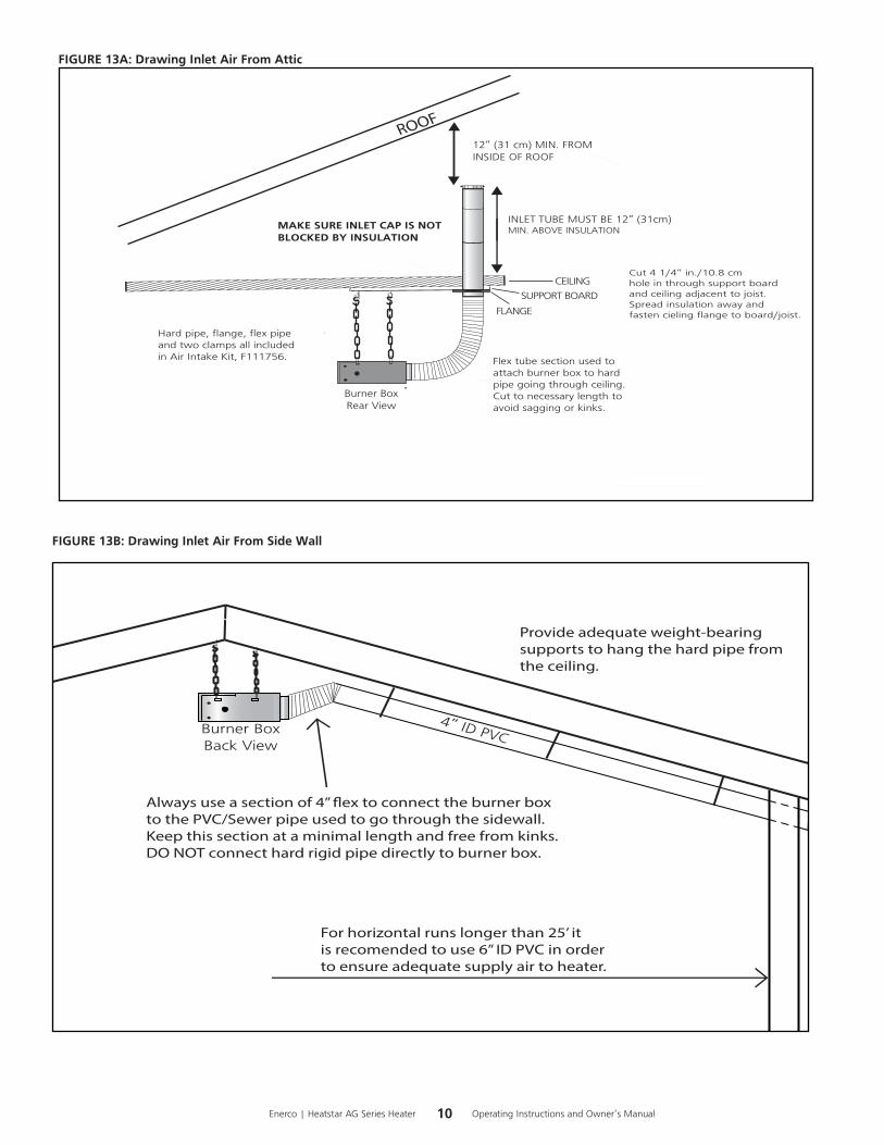
Itisrecommendedthatinletairbedrawninfromtheatticbutyoumayalsodrawinletairfromthesidewallforhouseswithoutanattic(Seefigures13Aand13B). Airinletterminationsshallnotbeaffectedbybuildingventilationfans.Airintakekit,F111756,isavailableforpurchasetocompletetheinstallationwhendrawingairthroughtheattic.Whendrawingairthroughthesidewallsupplieswillhavetobeobtainedthroughanoutsidesource.
IMPORTANT:
•DO NOT draw inlet air from inside the poultry confinement area.
•If the attic has a slight negative pressure or contaminants are present in the air, an outside combustion air supply to the heaters is strongly recommended.
•The pressure switch will not close causing the heater not to operate if the intake is blocked by insulation in the attic. We recommend double checking that the intake isn't blocked after initial installation as well as in betweeen flocks when it is known that the attic has blown in and loose insulation.
•Always attach your air inlet system to the burner box with a flexible section. This piece should be free of kinks and as straight as possible, no more than one 90° bend.
Ventilation
Ventilationequalto4CFMper1,000BTU/HRfiringratemustbeprovidedinunventedheaterinstallations.
10Enerco | Heatstar AG Series Heater Operating Instructions and Owner’s Manual
CEILING
Burner BoxRear View
12” (31 cm) MIN. FROM INSIDE OF ROOF
INLET TUBE MUST BE 12” (31cm)MIN. ABOVE INSULATION
Cut 4 1/4” in./10.8 cmhole in through support boardand ceiling adjacent to joist. Spread insulation away and fasten cieling flange to board/joist.
ROOF
MAKE SURE INLET CAP IS NOTBLOCKED BY INSULATION
Flex tube section used to attach burner box to hard pipe going through ceiling.Cut to necessary length toavoid sagging or kinks.
Hard pipe, flange, flex pipeand two clamps all includedin Air Intake Kit, F111756.
SUPPORT BOARD
FLANGE
FIGURE 13A: Drawing Inlet Air From Attic
FIGURE 13B: Drawing Inlet Air From Side Wall
Burner BoxBack View
4” ID PVC
Always use a section of 4” �ex to connect the burner boxto the PVC/Sewer pipe used to go through the sidewall.Keep this section at a minimal length and free from kinks. DO NOT connect hard rigid pipe directly to burner box.
For horizontal runs longer than 25’ it is recomended to use 6” ID PVC in orderto ensure adequate supply air to heater.
Provide adequate weight-bearing supports to hang the hard pipe from the ceiling.

11 Operating Instructions and Owner’s ManualEnerco | Heatstar AG Series Heater
FIGURE 15: Gas Line Connection with Stainless Steel Flex Gas Connector
Nipple
Shuto� Valve
Nipple
Tee
Nipple
Cap
Burner Box
Stainless Steel Flex Gas Connector
Nipple
2”12”
Included in Install Kit
SECTION 7 - WIRING
Heatersarenormallycontrolledbythermostats.Linevoltagethermostatsarewireddirectly(seeFigure16),24Vthermostatsarewireddirectlyusingtheterminalsonburnerbox(seeFigure18).HeatersmustbegroundedinaccordancewiththeNationalElectricCodeANSI/NFPA-70orcurrentCanadianElectricalCode,CSAC22.1.Heatersmayalsobecontrolledwithamanuallinevoltageswitchortimerswitchinplaceofthethermostat.
T
H
N
120v – 60 Hz
White
White
Green
Green
Supply Circuit
120v – 60 Hz
Supply Circuit
Burners(Maximum – 2 per Thermostat)
Burners(Maximum – 1 per Thermostat)
Black
Black
H
N
T
T
H
N
120v – 60 Hz
White
White
Green
Green
Supply Circuit
120v – 60 Hz
Supply Circuit
Burners(Maximum – 2 per Thermostat)
Burners(Maximum – 1 per Thermostat)
Black
Black
H
N
T
FIGURE 16: Line Voltage Thermostat Wiring FIGURE 17: Low Voltage Thermostat Wiring
SECTION 6 - GAS PIPINGReadapplicablewarningsonpage1&2beforeproceedingwithGasPipeinstallation.Improperinstallationmayresultinpropertydamage,severeinjury,ordeath.
Meterandservicemustbelargeenoughtohandlealltheburnersbeinginstalledplusanyotherconnectedload.Thegaslinewhichfeedsthesystemmustbelargeenoughtosupplytherequiredgaswithamaximumpressuredropof1/2”watercolumn.Localgassupplierwillusuallyhelpinplanningthecorrectgaspipingsize.
A1/2”pipeateachburnerlocationmustbelocatedandorientedasshownin(Figure14).Tochecksystempressure,putaplugged1/8”NPTtapinthegaslineattheconnectiontotheburnerfarthestfromthesupply.Beforeconnectingtheburnerstothesupplysystem,verifythatallhighpressuretestingofthegaspipinghasbeencompleted.Donothighpressuretestthegaspipingwiththeburnersconnected.
Followtheseinstructionstoensureaprofessionalgassupplyinstallation:
• Supportallgaspipingwithsuitablepipehangingmaterials.
• Usewroughtironorwroughtsteelpipeandmalleableironfitting.Allpipefittingsshouldbenewandfreefromdefects.
• UseL.P.gas-resistantjointcompoundonallpipethreads.
• Checkthepipeandtubingendsforleaksbeforeplacingheatingequipmentintoservice.Whencheckingforgasleaks,usesoapandwatersolution:NEVER USE AN OPEN FLAME.
Installtheflexgasconnectorasshown.Theflexgasconnectoraccommodatesexpansionoftheheatingsystemandallowsforeasyinstallationandserviceoftheburner.Theshut-offvalvemustbeparalleltoburnergasinlet.The2"displacementshownisforthecoldcondition.Thisdisplacementmayreducewhenthesystemisfired.
Heater Movement
Heater MovementHeater Movement
Heater Movement
FIGURE 14: Incorrect Gas Line Connection with Stainless Steel Flex Gas Connector
• NOTE: Jet heaters come with the thermostat connection jumped out with a piggyback connector inside the burner box to pro-vide a constant call for heat. If the themostat junction needs utilized, you will need to open up the box and attach these wires to the bushing on the back of the burner box.
12Enerco | Heatstar AG Series Heater Operating Instructions and Owner’s Manual
LADDER DIAGRAM
SECONDARY - 24V
T1PRIMARY - 120V
L1 N
PCB
PCB
L1
IND M
120VLED
PCB IGNIGNITER/FLAME SENSOR
BURNER
PCBPSWPCB TH
T'STAT (Optional)
JUMPER (Optional)
24 VAC PCB
PRESSURE SWITCH
GV PCBPCB V1 V2 GND
Earth &Chassis Ground
24VLED
V2GND24 VAC
L1
IND
NC
V1
PSW
TH
IGN FC-
FC+
LED
L1
T1
Prim
ary
Sec
ond
ary
120VLED
M
24VLED
GAS VALVE
N
Earth Ground
Pressure Switch
To Thermostat(Optional)
W24V
BURNER
IGNITER / FLAME SENSOR
CONTROL BOARD
Chassis Wiring Is 18 AWG / 105 Degrees C / @ 600 VoltsIgniter Wire Is 16 AWG / 25 KVDC / 10 KVDCCrimp Caps Are # CE5 / 105 Degrees CReplace Any Wiring With Same RatingsAll Quick Connects Are Fully Insulated (Except Igniter)
WHITE WHITE
WHITE
WHITE
GREEN
GREEN
GREEN
GREEN
GREEN
GREEN
BLACK
BLACK BLACK
BLACK
YELLOW
RED
BLUE
BLACK
GREEN
RED
BLACK
YELLOW
YELL
OW
ORANGE
RED
RED
CONNECTION DIAGRAM
Earth &Chassis Ground
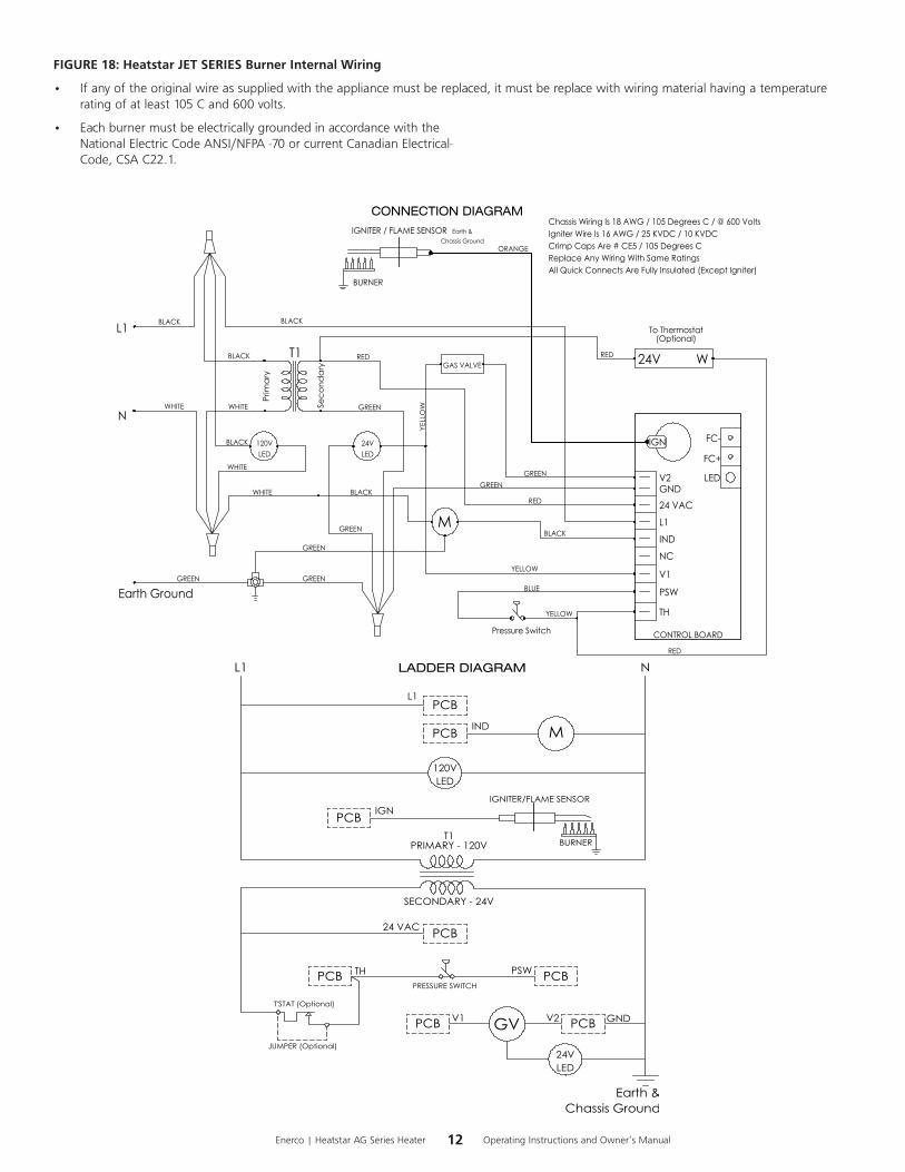
FIGURE 18: Heatstar JET SERIES Burner Internal Wiring
• Ifanyoftheoriginalwireassuppliedwiththeappliancemustbereplaced,itmustbereplacewithwiringmaterialhavingatemperatureratingofatleast105°Cand600volts.
• EachburnermustbeelectricallygroundedinaccordancewiththeNationalElectricCodeANSI/NFPA-70orcurrentCanadianElectrical-Code,CSAC22.1.
13 Operating Instructions and Owner’s ManualEnerco | Heatstar AG Series Heater
WHAT TO DO IF:
Blower Motor 1.Isthethermostatcallingforheat?Isthere Fails to Run: 120Vatthemotorterminals?
2.Checkblowerforobstructions.Replaceblowerifnecessary.
1.Checkigniterfordamageorexcesscarbon.Replaceifnecessary.
2.Checkforobstructionstotheairinletandoutlet.
3.Checkwiringandhoseconnectionstotheairswitch.Replaceifnecessary.
4.Checkvoltagesattransformerprimaryandsecondary.Replacetransformerormoduleifnecessary.
Valve Does Not Gaspressuredownstreamofgascontrolcan Open: bemeasuredbyusingamanometerand
connectingtopressuretaponvalve.
1.ChecktoseeifgasvalveswitchheaterisON.
2.Supplygaspressurecanbecheckedat1/8”NPTpressuretaponheaterexternalmanualvalve.
3.Checktoseeifgascontrolisopening:nomanifoldpressureindicatesvalveisclosed.
Ifthevalveisclosed,eitherthegasvalveortheignitionmoduleisfaulty.
WARNING:Donotdisconnectgroundleadsinsideheater.Donotinterchangegroundedandungroundedleadsontransformerorignitionmodule.
SECTION 8
Operation & MaintenanceSequence of Operation
1. Turnthethermostatup.Whenthethermostatcallsforheat,blowermotorwillenergize.
2. WhenthemotorapproachesnominalrunningRPM,theairprovingswitchclosesandactivatestheignitionmodule.
3. Oncetheignitersparks,thegasvalveisenergized.
4. Ifaflameisdetected,thegasvalveremainsopen.Whenthecallforheatissatisfied,andthesystemcontrolmechanismde-energizestheburnerlinevoltagesupply,thegasvalvesareturnedoff.
5. Ifnoflameisdetected,thegasvalveisclosed,andapurgeperiodbegins.Afterthepurge,themoduleactstopowertheigniterforasecondwarm-upperiod,andasecondtrialforignitionperiod.Ifflameisstillnotestablished,athirdandfinalpurge,warm-up,andtrialcyclebegins.Afterthreetrials,themodulewilllockoutuntilreset.Resetisaccomplishedbyremovingpowerfromthemoduleforatleastfive(5)seconds(thermostatcyclerequired.)
6. Ifflameisestablishedandlostonthefirstorsecondtrial,thegasvalveisturnedoff,apurge,warm-up,andtrialforignitionwilloccuronathree-trialmodule,onlythreetrialsforignitionareallowedperthermostatcycle.
Maintenance
Forbestperformance,thefollowingmaintenanceproceduresshouldbeperformedbeforeeachheatingseason:
1. Besuregasandelectricalsupplytoheaterareoffbeforeperforminganyserviceormaintenance.
2. Checkconditionofblowerscrollandmotor.Dirtanddustmaybeblownoutwithcompressedair,oravacuumcleanermaybeused.Whenusingcompressedairdonotexceed30psi.
3. Checkconditionofburner.Carefullyremoveanydustordebrisfrominsidetheburnerboxandthefaceoftheburnerventuri.
4. Inspecttheigniter.Replaceigniterifthereisexcessivecarbonresidue,erosion,breakageorotherdefects.
5. Checktheinsideofthefiringtubewithaflashlight.Ifcarbonorscalearepresent,scrapeoutthedepositswithawirebrushorrod,ormetalplateattachedtoawoodenpole.
•Tubesandreflectorscanbepowerwashedbut*DO NOT*powerwashtheburnerbox.
6. Checktheventcapforsootordirt.Aftercleaningasnecessary,re-attachtheflapperorventcaptotheheater.
7. Checktheairintakesystem,besurethatthetopisnotblockedintheattic.Also,emptycontentsofairintakesystemwhetheryour'reusingtraporflexpipetotheattic.
8. Checktomakesurethe4boltsconnectingthetubestoeachotheraretight,re-tightenifneeded.
9. Checkthatthefirstreflectorstillhasthesteelretentionwireconnectedtotheburnerbox.
10. Checkventcapandfreshairinlettoseethattheyhavenotbeenblockedduringthenon-heatingseason.Ifeitherpipeisrestricted,theairswitchwon’tclose,resultinginano-heatsituation.
Aqualifiedserviceagencyshouldbecontactedforserviceotherthanroutinemaintenance.
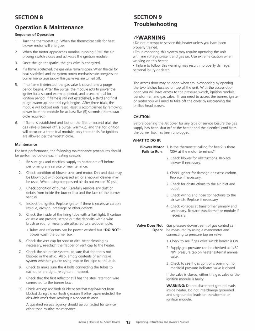
SECTION 9Troubleshooting
WARNING•Donotattempttoservicethisheaterunlessyouhavebeenproperlytrained.•Troubleshootingthissystemmayrequireoperatingtheunitwithlinevoltagepresentandgason.Useextremecautionwhenworkingonthisheater.•Failuretofollowthiswarningmayresultinpropertydamage,personalinjuryordeath.
Theaccessdoormaybeopenwhentroubleshootingbyopeningthetwolatcheslocatedontopoftheunit.Withtheaccessdooropenyouwillhaveaccesstothepressureswitch,ignitionmodule,transformer,andgasvalve.Ifyouneedtoaccesstheburner,igniter,ormotoryouwillneedtotakeoffthecoverbyunscrewingthephillipsheadscrews.
CAUTION:
BeforeopeningtheJetcoverforanytypeofservicebesurethegassupplyhasbeenshutoffattheheaterandtheelectricalcordfromtheburnerboxhasbeenunplugged.
14Enerco | Heatstar AG Series Heater Operating Instructions and Owner’s Manual
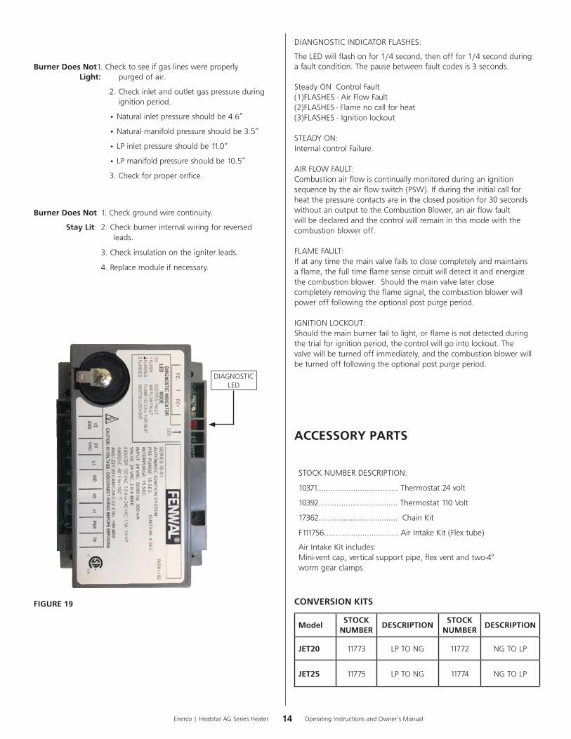
DIAGNOSTICLED
DIANGNOSTICINDICATORFLASHES:
TheLEDwillflashonfor1/4second,thenofffor1/4secondduringafaultcondition.Thepausebetweenfaultcodesis3seconds.
SteadyON ControlFault(1)FLASHES-AirFlowFault(2)FLASHES-Flamenocallforheat(3)FLASHES-Ignitionlockout
STEADYON:InternalcontrolFailure.
AIRFLOWFAULT:Combustionairflowiscontinuallymonitoredduringanignitionsequencebytheairflowswitch(PSW).Ifduringtheinitialcallforheatthepressurecontactsareintheclosedpositionfor30secondswithoutanoutputtotheCombustionBlower,anairflowfaultwillbedeclaredandthecontrolwillremaininthismodewiththecombustionbloweroff.
FLAMEFAULT:Ifatanytimethemainvalvefailstoclosecompletelyandmaintainsaflame,thefulltimeflamesensecircuitwilldetectitandenergizethecombustionblower.Shouldthemainvalvelaterclosecompletelyremovingtheflamesignal,thecombustionblowerwillpowerofffollowingtheoptionalpostpurgeperiod.
IGNITIONLOCKOUT:Shouldthemainburnerfailtolight,orflameisnotdetectedduringthetrialforignitionperiod,thecontrolwillgointolockout.Thevalvewillbeturnedoffimmediately,andthecombustionblowerwillbeturnedofffollowingtheoptionalpostpurgeperiod.
ACCESSORY PARTS
STOCKNUMBERDESCRIPTION:
10371....................................Thermostat24volt
10392...................................Thermostat110Volt
17362...................................ChainKit
F111756……………………………AirIntakeKit(Flextube)
AirIntakeKitincludes:Mini-ventcap,verticalsupportpipe,flexventandtwo-4"wormgearclamps
CONVERSION KITS
ModelSTOCK
NUMBERDESCRIPTION
STOCK NUMBER
DESCRIPTION
JET20 11773 LPTONG 11772 NGTOLP
JET25 11775 LPTONG 11774 NGTOLP
FIGURE 19
Burner Does Not1.Checktoseeifgaslineswereproperly Light: purgedofair.
2.Checkinletandoutletgaspressureduringignitionperiod.
•Naturalinletpressureshouldbe4.6”
•Naturalmanifoldpressureshouldbe3.5”
•LPinletpressureshouldbe11.0”
•LPmanifoldpressureshouldbe10.5”
3.Checkforproperorifice.
Burner Does Not 1.Checkgroundwirecontinuity.
Stay Lit: 2.Checkburnerinternalwiringforreversedleads.
3.Checkinsulationontheigniterleads.
4.Replacemoduleifnecessary.

15 Operating Instructions and Owner’s ManualEnerco | Heatstar AG Series Heater
Parts List for JET Tube Heaters
Item Stock # Description QTY
1 F102090 JET25BurnerBox-NG 1
F102095 JET25BurnerBox-LP
2 02976 3.5"TubeCoupler 1
3 06455 3.5"AluminizedTubew/Flange 1
4 12396 TubeFlangeGasket 1
5 98014 3/8"-16Bolts 4
6 06456 4"HRSTubew/Flange 1
7 14612 4"TubeConnectionCoupler 1
8 14616 4"TubeCouplerKey 1
9 06453 5'Long4"HRSTube 1
Item Stock # Description QTY
1 F102080 JET20BurnerBox-NG 1
F102085 JET20BurnerBox-LP
2 02975 3"TubeCoupler 1
3 06454 3"AluminizedTube 1
4 12394 TubeFlangeGasket 1
5 98014 3/8"-16Bolts 4
6 06457 3.5"HotRolledSteelTube 1
7 02976 3.5"TubeCoupler 1
8 14582 3.5"-4."VentCapReducer 1
Item Stock # Description QTY
10 19021 4"VentAdapter 1
11 19041 4"VentCap 1
12 00419 ReflectorEndCaps 2
13 00422 10'ReflectorwithSteelWire 1
14 00418A Standard10'Reflector 1
15 00417A Standard5'Reflector 1
16 14585P 4"TubeHanger 3
17 14573 3.5"TubeHanger 2
18 19012 SteelReflectorRetentionWire(Includedwithitem13)
1
19 03345 10'Turbulator(Insideendoftube)
1
JET25
JET20
Item Stock # Description QTY
9 19041 4"VentCap 1
10 00422 10'ReflectorwithSteelWire 1
11 00418A Standard10'Reflector 1
12 00419 ReflectorEndCaps 2
13 19012 SteelReflectorRetentionWire(Includedwithitem10)
1
14 14572 3"TubeHangers 2
15 14573 3.5"TubeHangers 2
16 03444 7'Turbulator(Insideendoftube)
1
1
3
6
4
5
2
78
9
10
11
12
13
14
1512
16
1
2
3
4
56
7
8
910
11
12
13
14
1512
16
17
18
18

16Enerco | Heatstar AG Series Heater Operating Instructions and Owner’s Manual
ITEM# EGI# DESCRIPTION QTY
1 02999 ENCLOSURE,AG,TUBE,BOXBURNER 1
2 02963 COVER,AG,TUBE,BOXBURNER 1
3 00055 GASVALVENG 1
4 00056 GASVALVELP 1
5 07376 MOTOR 1
6 02968 VENTADAPTER 1
7 02964 POWERCORD 1
8 60889 POWERCORDSTRAINRELIEF 1
9 02721 THERMOSTATBUSHING 1
10 08364A TRANSFORMER 1
11 02970 IGNITIONMODULE 1
12 02973 BURNERASSEMBLY 1
13 60729 IGNITER/FLAMESENSORELECTRODE 1
14A 02969 JET25PRESSURESWITCH1
14B 02979 JET20PRESSURESWITCH
15 12397 TUBEFLANGEGASKET 1
ITEM# EGI# DESCRIPTION QTY
16A 02967 JET253.5"TUBEFLANGE1
16B 02966 JET203"TUBEFLANGE
17 02720 ORIFICEHOLDERFITTING 1
18A 05712 JET25NGORIFICE
118B 05718 JET20NGORIFICE
19A 05733 JET25LPORIFICE
19B 05737 JET20LPORIFICE
20 98012 BOLT5/16"-18x1" 4
21 98902 SCREW#8-32x3/8" 10
22 98907 SCREW#8-32x1" 2
23 98901 SCREW#8-32x1/4" 4
24 98692 NUT#8-32 9
NS 60845 120V"POWERON"LEDLIGHT 1
NS 60846 24V"GASVALVEON"LEDLIGHT 1
NS 02987 PRESSURESWITCHTUBE-LONG10" 1
NS 02933 PRESSURESWITCHTUBE-SHORT5" 1
JET 20/25 PARTS LIST

17 Operating Instructions and Owner’s ManualEnerco | Heatstar AG Series Heater
WARNING:USEONLYMANUFACTURER’SREPLACEMENTPARTS.USEOFANYOTHERPARTSCOULDCAUSEINJURYORDEATH.REPLACEMENTPARTSAREONLYAVAILABLEDIRECTFROMTHEFACTORYANDMUSTBEINSTALLEDBYAQUALIFIEDSERVICEAGENCY.
FOR INFORMATION REGARDING SERVICE OR PARTS:
Contactyourlocalheatingservicetechnicianordealer.
FOR ADDITIONAL INFORMATION:
PleasecallToll-Free866-447-2194—www.heatstarbyenerco.comOurofficehoursare8:00AM—5:00PM,EST,MondaythroughFriday.Pleasehavethemodelnumber,serialnumberanddateofpurchaseready.
LIMITED WARRANTY
Thecompanywarrantsthisproducttobefreefromimperfectionsinmaterialorworkmanship,undernormalandproperuseinaccordancewithinstructionsofTheCompany,foraperiodof1yearontheboxand2yearsonthetubesfromthedateofdeliverytothebuyers.
TheCompany,atitsoption,willrepairorreplaceproductsreturnedbythebuyertothefactory,transportationprepaidwithinsaidwarrantyperiodandfoundbytheCompanytohaveimperfectionsinmaterialorworkmanship.
Ifapartisdamagedormissing,callourCustomerServiceDepartmentat866-447-2194.
AddressanyWarrantyClaimstotheCustomerServiceDepartment,Heatstar,Inc,4560W.160THST.,CLEVELAND,OHIO44135.Includeyourname,addressandtelephonenumberandincludedetailsconcerningtheclaim.Also,supplyuswiththepurchasedateandthenameandaddressofthedealerfromwhomyoupurchasedourproduct.
TheforegoingisthefullextentoftheresponsibilityoftheCompany.Therearenootherwarranties,expressorimplied.Specificallythereisnowarrantyoffitnessforaparticularpurposeandthereisnowarrantyofmerchantability.InnoeventshalltheCompanybeliablefordelaycausedbyimperfections,forconsequentialdamages,orforanychargesoftheexpenseofanynatureincurredwithoutitswrittenconsent.Thecostofrepairorreplacementshallbetheexclusiveremedyforanybreachofwarranty.Thereisnowarrantyagainstinfringementofthelikeandnoimpliedwarrantyarisingfromcourseofdealingorusageoftrade.Thiswarrantywillnotapplytoanyproductwhichhasbeenrepairedoralteredoutsideofthefactoryinanyrespectwhichinourjudgmentaffectsitsconditionoroperation.
Somestatesdonotallowtheexclusionorlimitationofincidentalorconsequentialdamages,sotheabovelimitationorexclusionmaynotapplytoyou.ThisWarrantygivesyouspecificlegalrights,andyoumayhaveotherrightswhichvaryfromstatetostate.
Heatstar,Inc,4560W.160THST.,CLEVELAND,OHIO44135•866-447-2194©2019,Heatstar,IncAllrightsreserved
Heatstar,Increservestherighttomakechangesatanytime,withoutnoticeorobligation,incolors,specifications,accessories,materialsandmodels.
OPERATING INSTRUCTIONS AND OWNER’S MANUAL
120VM
ODELS
by ENERCO
JET20JET25
18Enerco | Heatstar AG Series Heater Operating Instructions and Owner’s Manual
ADVERTENCIA: La instalación, ajuste, alteración, reparación o mantenimiento inadecuados puede causar daños materiales, lesiones o la muerte. Lea completamente las instrucciones de instalación, operación y mantenimiento antes de instalar o reparar este equipo.
— QUÉHACERSIDETECTAOLORAGAS
• Abralasventanas. • NOintenteencenderningúnartefacto. • NOuseinterruptoreseléctricos. • NOtoqueningúninterruptoreléctrico;nouseningúnteléfonoeneledificio.
• Llameinmediatamentealacompañíalocaldegasysigalasinstruccionesquerecibadeella. (Lainstalaciónylareparacióndebenserrealizadasporuninstaladorcalificado,agenciadereparacionesola compañíadegas). • Sinosepuedecomunicarconlacompañíadegas,llamealosbomberos.
POR SU SEGURIDAD: -Este calefactor está diseñado como un calefactor radiante de gas para el calentamiento de edificios de confinamiento de aves y cerdos. Si está considerando usar este producto para cualquier aplicación distinta a su uso previsto, comuníquese con Heatstar, Inc.-Noalmaceneniutilicegasolinaniningúnotrovapornilíquidoinflamablecercadeestenideningúnotroartefacto.
ADVERTENCIA: Sinosesiguenestasinstruccionesalpiedelaletra,podríaproducirseunincendioounaexplosiónqueprovocaríadañosmateriales,lesionespersonalesomuertes.
18683Heatstar,IncGroup,Inc.,4560W.160THST.,CLEVELAND,OHIO44135•866-447-2194
INSTRUCCIONES DE OPERACIÓN Y MANUAL DEL USUARIO
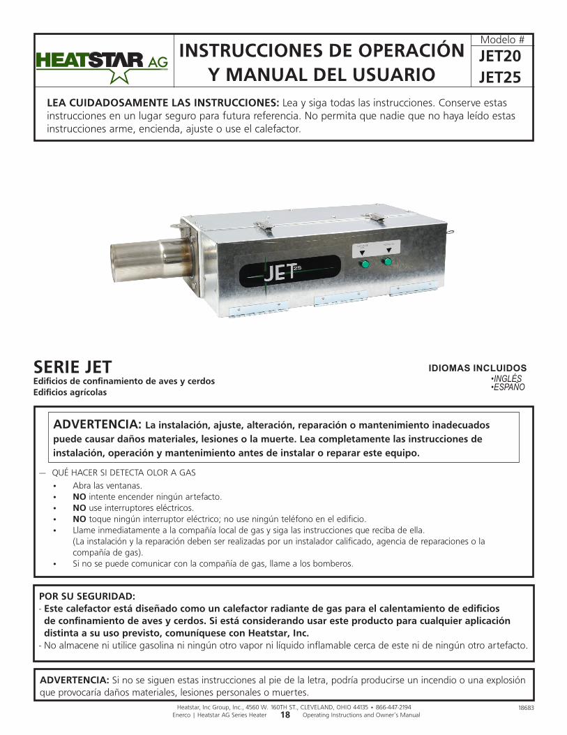
LEA CUIDADOSAMENTE LAS INSTRUCCIONES:Leaysigatodaslasinstrucciones.Conserveestasinstruccionesenunlugarseguroparafuturareferencia.Nopermitaquenadiequenohayaleídoestasinstruccionesarme,encienda,ajusteouseelcalefactor.
Modelo#
by ENERCO
IDIOMAS INCLUIDOSSERIE JETEdificios de confinamiento de aves y cerdos Edificios agrícolas
•INGLÉS•ESPAÑO
JET20JET25

19 Operating Instructions and Owner’s ManualEnerco | Heatstar AG Series Heater
ADVERTENCIA: PELIGRODEINCENDIO,QUEMADURAS,INHALACIÓNYEXPLOSIÓN.MANTENGALOSCOMBUSTIBLESSÓLIDOSCOMOMATERIALESDECONSTRUCCIÓN,PAPELOCARTÓNAUNADISTANCIASEGURADELCALEFACTORTALCOMOLORECOMIENDANLASINSTRUCCIONES.NUNCAUSEELCALEFACTORENESPACIOSQUECONTIENENOPODRÍANCONTENERCOMBUSTIBLESVOLÁTILESOPRODUCTOSCOMOGASOLINA,SOLVENTES,DILUYENTEDEPINTURAOPRODUCTOSQUÍMICOSDESCONOCIDOS.
ADVERTENCIA GENERAL DE PELIGRO:ELNOCUMPLIRCONLASPRECAUCIONESEINSTRUCCIONESQUEVIENENCONESTECALEFACTORPUEDECAUSARLAMUERTE,LESIONESGRAVESYPÉRDIDASYDAÑOSMATERIALESDERIVADOSDELPELIGRODEINCENDIO,EXPLOSIÓN,QUEMADURAS,ASFIXIA,ENVENENAMIENTOCONMONÓXIDODECARBONO,Y/ODESCARGASELÉCTRICAS.SOLOLASPERSONASQUEENTIENDANYPUEDANSEGUIRLASINSTRUCCIONESDEBENUSAROMANTENERESTECALEFACTOR.SINECESITAAYUDAOINFORMACIÓNACERCADELCALENTADOR,COMOUNMANUALDEINSTRUCCIONES,ETIQUETAS,ETC.,PÓNGASEENCONTACTOCONELFABRICANTE.
ADVERTENCIA:SUSEGURIDADESIMPORTANTEPARAUSTEDYPARALOSDEMÁS,ASÍQUEPORFAVORLEAESTASINSTRUCCIONESANTESDEUTILIZARELCALEFACTOR.
CONTENIDO
SECCIÓN1INTRODUCCIÓN...................................2
SECCIÓN2PLANIFICACIÓN...................................3
SECCIÓN3INSTALACIÓNYARMADO...................5
SECCIÓN4ESPECIFICACIONESDEINGENIERÍA......9
SECCIÓN5TOMADEAIRE/VENTILACIÓN.............9
SECCIÓN6TUBERÍADEGAS............................... 11
SECCIÓN7CABLEADO........................................ 11
SECCIÓN8OPERACIÓNYMANTENIMIENTO...... 13
SECCIÓN9RESOLUCIÓNDEPROBLEMAS........... 13
PARTESACCESORIAS........................................... 14
SECCIÓN10PARTESDEREPUESTO..................... 15
INFORMACIÓNDELAGARANTÍA........................20
ADVERTENCIA: ESTE PRODUCTO PUEDE EXPONERLO A PRODUCTOS QUÍMICOS, INCLUYENDO PLOMO Y COMPUESTOS DE PLOMO, QUE DE ACUERDO CON EL ESTADO DE CALIFORNIA PRODUCEN CÁNCER Y DEFECTOS DE NACIMIENTO U OTROS DAÑOS REPRODUCTIVOS.
POR MAYOR INFORMACIÓN, VISITE WWW.P65WARNINGS.CA.GOV
SECCIÓN 1: Introducción LosmodelosJETsoncalefactoresinfrarrojoseconómicos,dearmadoenellugar,quesonfácilesdeinstalaryquerequierenmuypocomantenimiento.Estándiseñadosparabrindarañosdefuncionamientoeconómicosinproblemas.
Verificación del envíoCompareelenvíocontralalistadeenvíoparaverificarquenolefaltenada.Además,reviselascajasparaverificarquenotengandañosexternos.Anotecualquiercosaquefaltey/olosdañosexternosalascajasenlalistadeenvíoantelapresenciadelcamioneroquerealizalaentrega.Elcamionerodeberáreconocercualquierfaltanteodañocolocandosusinicialesenlalistadeenvíoconloscomentarios.Realiceinmediatamenteelreclamopormaterialesdañadosofaltantesquenohayanotadoalmomentoderecibirlos,alaempresadetransporteyalrepresentantedelafábricaHeatstar,Inc.
Responsabilidad del instaladorTodosloscalefactoresylastuberíasdegasasociadasdebenserinstaladasdeacuerdoconlasespecificacionescorrespondientesylainstalacióndebeserrealizadaúnicamenteporempresas(opersonas)correctamentecalificadasparaestetipodetrabajo.Consulteconinspectoreslocalesdeedificios,losbomberososurepresentantelocaldelafábricaHeatstarporrecomendaciones.
LainstalacióndeloscalefactoresJETsebasaenlainformaciónsuministradaenundiagramadedistribución,quejuntoconlasnormasyreglamentacionesmencionadasanteriormenteconstituyenlainformaciónbásicanecesariaparacompletarlainstalación.Elinstaladordeberáproporcionartodoelmaterialnecesarioquenoseincluyecomoequipoestándar,yessuresponsabilidadverificarquedichomaterialylosmétodosdeinstalaciónqueutiliceconstituyanuntrabajodecalidadprofesionalydeacuerdocontodaslasnormascorrespondientes.
LosrepresentantesdelafábricaHeatstar,Inc.cuentanconentrenamientoyexperienciaenesteequipoylospuedellamarporsugerenciasacercadelainstalación,loquepuedeahorrarlematerialycostos.

20Enerco | Heatstar AG Series Heater Operating Instructions and Owner’s Manual
SECCIÓN 2: PlanificaciónDebenrespetarselassiguientesnormaseinstruccionesalplanificarlainstalacióndeestecalefactorJET.Ademásdeestasinstrucciones,hayquerespetarcuidadosamentelasadvertencias,yaqueunainstalacióninadecuadapodríacausardañosmateriales,lesionesolamuerte.
Normas nacionales y reglamentaciones correspondientes
Normas de gas:
• Sedebeutilizareltipodegasqueseindicaenlaplacadeidentificación.Lainstalacióndebecumplirconlasnormaslocales,conlasrecomendacionesdelacompañíalocaldegasyconelCódigonacionaldelgascombustible,ANSIZ223.1–últimaversión,(igualqueconelBoletínNFPA54)(Códigodeinstalacióndegasnaturalypropano,CSAB149.1)paraCanadáúnicamente.
•Debemantenerselaseparaciónentreelcalefactorysuventilaciónyelmaterialcombustibleadyacente(yaseapartedeledificioosucontenido)paracumplirconlanormadeinstalacióndeartefactosagasytuberíasdegas,NFPA-54/ANSIZ223.1–últimaversión,elCódigonacionaldelgascombustible(Códigodeinstalacióndegasnaturalypropano,CSAB149.1)paraCanadáúnicamente.
Lugares peligrosos:
Cuandoexistalaposibilidaddeexposiciónamaterialcombustiblesuspendidoenelaireoenformadevapor,consulteconlosbomberoslocales,lacompañíadeseguroscontraincendiouotrasautoridadesparaqueapruebenlainstalaciónpropuesta.
Consideraciones críticasEstemodeloJETesuncalefactorsuspendido.Porlotanto,suestabilidad,flexibilidadyseguridadsonmuyimportantes.Antesdecomenzarconlainstalación,verifiquequeelsistemapuedacumplirconlossiguientesrequisitos.•Mantenerlasdistanciasespecificadasacombustiblesyunadistanciaseguraamateriales,equiposyestacionesdetrabajosensiblesalcalor.
•Lasdistanciasacombustiblesindicadasrepresentanunatemperaturasuperficialde90°F(30°C)porencimadelatemperaturaambiente.Losmaterialesdeconstrucciónconbajatoleranciaalatemperatura(comoelplástico,revestimientovinílico,lona,etc.)podríandegradarseatemperaturasmenores.Esresponsabilidaddelinstaladorelasegurarsedequelosmaterialesadyacentesesténprotegidoscontraladegradación.
•Brindaraccesoalosquemadoresparareparaciones,preferentementedeamboslados,porencimaypordebajodelquemadorparapoderremoverlo.
•Respetarsiemprelasdistanciasmínimasamaterialescombustiblesindicadasenlapágina4.
•Planificarlossoportesparaellugar(verlaFigura2A-Bcomenzandoenlapágina6).
• Lainstalacióndebecumplirconlasnormaslocalesdeconstrucción,ysinoexistennormaslocales,conelCódigonacionaldelgascombustible,ANSIZ223.1/NFPA54(Códigodeinstalacióndegasnaturalypropano,CSAB149.1)paraCanadáúnicamente.
•Siseutilizaunafuentedeenergíaeléctricaexterna,elcalefactor,alinstalarlo,deberáestarconectadoeléctricamenteatierradeacuerdoconlaNormaeléctricanacional,ANSI/NFPA70oconlaNormadeElectricidadCanadiense,CSAC22.1.
Procedimiento de instalaciónAprovechealmáximolaestructurasuperiordeledificio,vigas,viguetas,largueros,etc.dedondepuedacolgarelcalefactor.Noexisteunaúnicasecuenciadeinstalaciónparalatubería.Laobservacióndellugarusualmentelerevelaráunasecuencialógica.Comiencelainstalaciónenellugarcondimensionesmáscríticas.Losdeflectoresylastuberíassepuedenirinstalandoamedidaquevaavanzando.Ajustecuidadosamentelainclinacióndelsistemaencadaposiciónparanivelarelcalefactor.Useunainclinaciónhaciaabajodemediapulgadaporcada20pies(alejándosedelquemador).
LO QUE NO DEBE HACER
Probarlatuberíadegasconaltapresión(másde1/2PSIG)sincerrarlallavedecortedealtapresión.Elnohacerlodañaríalosquemadores.
LO QUE DEBE HACER
Familiaríceseconlasnormaslocalesynacionales.
Desarrolleunprocedimientoplanificado,paraahorrarmaterialytrabajodurantelainstalación.
Verifiquequetengatodoelmaterialylosequiposenellugarantesdecomenzarconlainstalación.
Permitalaexpansióntérmicadelastuberías.
Instaleelconectordegassolamentecomosemuestraenlasinstrucciones(verlaFigura14y15delapágina11).
Usetornillosautorroscantesdondelosreflectoressesuperponganparaasegurarsedequenoseseparen.
Fijeelcablederetencióndelreflectoralacajadelquemadoroalacadenaquesuspendelacajadelquemador.Elcablevieneunidoaunodelosreflectores.Consultelasinstruccionesenconjuntodetubopormásdetalles.
Brindeunaaberturade1pulgada2deairelibreporcada1.000BTU/hdeentradadelcalefactor(peronomenosde100pulgadas2)enespacioscerrados.Unaaberturadebeestardentrodelas12"deltechoylaotradentrodelas12"delpisodelrecinto.

21 Operating Instructions and Owner’s ManualEnerco | Heatstar AG Series Heater
Distancia a combustiblesFigura 1: (ConsultelaTABLA1)
ADVERTENCIA: PELIGRO DE INCENDIO Y EXPLOSIÓN
PUEDE CAUSAR DAÑOS MATERIALES, LESIONES GRAVES O LA MUERTE.
Sedebenmantenerlasdistanciasmínimasamaterialescombustiblesentodaslassituaciones.Elnorespetarlasdistanciasmínimasamaterialescombustiblespuedecausardañosmateriales,lesionesgravesolamuerte.
Hayquetenercuidadoalhacerfuncionarelsistemacercadematerialescombustiblescomomadera,papel,goma,etc.Hayquetenerencuentalasparticiones,estantesdealmacenamiento,elevadores,laconstruccióndeledificio,etc.
LaTABLA1indicalasdistanciasmínimasaceptablesamaterialescombustibles.
Distancia a combustiblesTABLA 1:Distanciasmínimasamaterialescombustibles(uselaFigura1comoguía)
Tipodereflector
Posición HSJET20 HSJET25
Reflectorestándar
(horizontal)
A 12" 12"
B 36" 36"
C 55" 74"
D 36" 36"
E 72" 72"

22Enerco | Heatstar AG Series Heater Operating Instructions and Owner’s Manual
SECCIÓN 3: Instalación y armado
ACOPLEDETUBERÍA(14612)*USADOENJET25*
ENCASTREPARAELACOPLEDETUBERÍA(14616)*USADOENJET25*
GANCHOPARACOLGARLATUBERÍA-Tubode3”=14572-Tubode3,5”=14573-Tubode4”=14585P
JET20•10'-3"DEAluminizado(06454)•10'-3,5"DEAcero(06457)
JET20-DEFLECTORDETURBULENCIASDE7'(03444)JET25-DEFLECTORDETURBULENCIASDE10'(03445)
REFLECTOR-5'=00417A*SOLAMENTEJET25* -10'=00418A-10'concable=00422
CAJADELQUEMADOR
JET25•10'-3,5"DEAluminizado(06455)•10'-4"DEAcero(06456)•5'-4"DEAcero(06453)*SINREBORDE*
TUBERÍADELINTERCAMBIADORDECALOR
TAPADEVENTEO(19041)ADAPTADORDEVENTEO(14582)

23 Operating Instructions and Owner’s ManualEnerco | Heatstar AG Series Heater
ALUMINIZADO(SOLOlosprimeros10pies)yACEROLAMINADOENCALIENTE
Tubería del intercambiador de calorSesuministraenlongitudesde10pies(5piesincluidosconelJet25)
Alcolgarlostubosnotaráunacosturadesoldaduraalolargodeltubo.Alconectarlostubosesimportantenodejarestacosturadesoldaduramirandodirectamentehaciaarribaohaciaabajo,loqueaumentarálalongevidaddesusintercambiadoresdecalor.
Generalidades de armado
Intercambiador de 20 pies de largo. Largo total del calefactor es 21 pies 4 pulgadas. 6 puntos de suspensión como se indica.
Generalidades de armado
Intercambiador de 25 pies de largo. Largo total del calefactor es 26 pies 4 pulgadas. 7 puntos de suspensión como se indica.
Deflector de turbulenciasLoscalefactoresHeatstarAGJetvienencondeflectoresdeturbulenciassueltosenlacaja.Eldeflectordeturbulenciasdebecolocarseenelextremodeltubo,despuésdearmarlo.
ReflectoresAlternelassuperposicionescomosemuestraenladescripcióngeneral.Seindicalalongituddelreflectorylacantidaddesuperposición.Reflectorconcablederetenciónparausarmáscercadelacajadelquemador.Vealasinstruccionesincluidasconeljuegodetuberías.
10'2-1/2"
Mecanismo de acople de tuberíasElacoplamientodebeestarorientadoconunabarradeslizanteenlapartesuperior.(SeusasolamenteenJET25)
ArmeloscomponentesdelcalefactorcomosemuestraenlasFiguras2A,2B.Instalelosaccesoriosnecesariosdesuspensión,ganchosparavigas,cadenasovarillasenloslugarespredeterminados.Ajusteellargodelascadenasparalograrunapendienteuniforme.
Gancho para colgar tubos y reflectoresSerequieren2ganchosparacadatubo,ganchosdediferentestamañosparatubosdediferentestamaños.
Figura 2: Descripción de piezas del Heatstar JET
*JET25SOLAMENTE*
Figura 2A JET20
Figura 2B JET25
Armazón del quemadorDebeinstalarsesiemprehorizontalmente.

24Enerco | Heatstar AG Series Heater Operating Instructions and Owner’s Manual
FIGURA 4: Conexión de la funda del tubo de 4” (solamente JET25)
Elsegundotubodeaceroylaseccióndetuboadicionalde5’seconectanmedianteunacoplamientoenvolventequeseenganchaconunatrabacónica,ajustadaagolpes.Losextremosdeiniciodelmiembrodeacopleytrabaestánidentificadosmedianteorificiosde1/4"quesejuntanalcomenzaraarmarlo.Verifiquequelosextremosdeltuboesténalineadosyquetoquenlosretenesqueestándentrodelacople.Hayquemartillarlabarradeslizadorahastaqueelacoplequedebienajustadoalrededordelostubos.Elajustarlodemasiadocausaráunadistorsiónenelacopleoenelbordedeldeslizador,locualdisminuirálacapacidaddesujecióndelmismo.
DETALLES DE ARMADO DE REBORDE ACOPLAMIENTO - REFLECTOR
FIGURA 3: Conexión del reborde del tuboAlineelosorificiosparalospernosdelajunta,enelrebordedeltuboaluminizadoconlosorificiosparalospernosdelrebordedeltubodeacero.Eltuboaluminizadosedeslizarádentrodeltubodeacero,unavezquelosrebordesylajuntaesténalineados,uselos4pernosyrealiceelacopleconlas4tuercasadjuntas.Comoseindicóanteriormente,lascosturasdesoldaduraeneltubonodebenquedarmirandodirectamentehaciaarribaohaciaabajo.
Juegodecadena-Parte#17362
Unjuegodecadenasoportaunaseccióndetuberíade10'yunaseccióndereflectorde10'.
FIGURA 7: Detalles de suspensión típica
Tuercadefijación
ArandelaVigademadera
Arandela
Ganchoarosca3/8"(10mm)mínimo
Viga I
Ganchoparaviga
Comoserequiera
Gancho “S”
Ganchoparavigueta
Cercha
Viga de concreto
Anclaje
POSICIÓNDELREFLECTORHORIZONTAL(ESTÁNDAR)
tubo radiante
HORIZONTAL
GANCHO
REFLECTOR
PARTESUPERIOR
COSTADOPARTEINFERIOR
FIGURA 6: Gancho para colgar tubos y reflectoresAsegúresedetenerencuentaquecadacalefactorJetutilizadosganchosdediferentestamañosparalostubosdediferentestamaños.Paraunreflectorequilibrado,asegúresedequeelbuclede45°señaladoenlaimagendearribaquededelmismoladoparatodoslosreflectores.
FIGURA 5: Instalación de la tapa del extremo del reflectorLatapadelextremodelreflectorsedebecolocarencadaextremodelsistemadetubosutilizandolostornillosautorroscantesqueseproporcionan,comosemuestraenlasiguienteimagen.
Acople básico - 14612Encastre para el acople - 14616
ACOPLEDETUBERÍA
ENCASTREPARAELACOPLE
Ajustar
Aflojar
Orificio 1
Orificio 2
Acople
Bloque de impacto
Alarmarelacople,tengaencuentalasubicacionesdelosorificios1y2.
Orienteelacopleparaqueelbloquedeimpactoquedeporencimadelcentrodeltubo.

25 Operating Instructions and Owner’s ManualEnerco | Heatstar AG Series Heater
REDUCTORPARATAPADEVENTILACIÓN
TUBO ABRAZADERADELESCAPE
INSTALACIÓN DE TAPAS DE VENTILACIÓN Y ABRAZADERAS PARA TUBOS
FIGURA 9
MECANISMO DE ABRAZADERA(semuestraenlaFIGURA10)
1.Asegúresedetenertodaslaspiezasparaelmontaje: (1base,2soportes,2pernos(9/16")y2tuercas)
2.NOTA:ElladocurvodelaBasedebequedarhaciaarribayelladoplanoenlaparteinferior.
3.Alineeelsoportedemaneraqueelladocurvoquedehaciaadentro,hacialaabrazaderaydesliceeltornillo(9/16")atravésdelmismoparafijarelotrosoporte.Utilicelatuercaparaapretarlos.Repitaestoparaelotrotornilloylatuerca.
FIJE EL TUBO A LA CAJA DEL QUEMADOR(semuestraenlaFIGURA11)
1.Desliceeltubohastaquequedealrasconelrebordedelacajadelquemador.NOTA:laabrazaderamontadadebequedarholgadaenelrebordedelacajadelquemador.
2.Alineelaabrazaderademodoquecadatornilloytuercaquedenacadaladodelacosturaenlaqueseencuentraneltuboyelrebordedelacajadelquemador.
3.Aprietelaabrazaderaconunallavede9/16".
FIGURA 10
FIGURA 11
BASESOPORTEDEMONTAJE
PERNOS9/16
ABRAZADERA
SOPORTEDEMONTAJE
TUERCAS
ABRAZADERATUBO
Instalación de la tapa de ventilación de JET20(semuestraenlaFIGURA9)
1.Elreductorparatapadeventilaciónsedeslizasobreeltubode3,5".
2.Laabrazaderadeescapeseutilizaparacubrirlamitaddeltuboylamitaddelreductordeventilación.
3.Laabrazaderadeescapequedabienajustadaconunallavede9/16".
Instalación de la tapa de ventilación del JET251.Latapadeventilaciónhacetopecontraeltubode4".
2.Eladaptadordeventilaciónseutilizaparacubrirlamitaddeltuboylamitaddelatapadeventilaciónde4”.
3.EladaptadordeventilaciónsefijaconundestornilladorPhillips.
26Enerco | Heatstar AG Series Heater Operating Instructions and Owner’s Manual
Sección 4
Especificaciones de ingenieríaA. Quemador y controles del quemador1.Losquemadoresdebensercapacesdeencenderconunadelasopcionesdecombustibleespecificadasenlaetiquetadeclasificación:GasnaturaloPL.
2.Losquemadoresdebensuministrarseparatrabajaracualquieradelosnivelesdeentradaespecificados.
JET20 80.000BTU/H.JET25 100.000BTU/H.
3.Elquemadordebecontarconunsistemadecontroldeignicióndechispadirecta,conundispositivodeapagadodeigniciónal100%.Laalimentaciónsuministradaacadacalefactordebesermonofásicade120V,60Hz.Losquemadoresdebentenerunaespecificaciónde1,0A(funcionamiento)y5,0A(arranque).
4.Elquemadordebeestarequipadoconunaproteccióntérmicacontrasobrecargasdelmotoryconuninterruptordepresióndeseguridadparalapresióndelairedecombustión.
5.Cuandoseespecifique,enambientescontaminados,elquemadordebesercapazdesuministraraireexterioracadaquemadorparamantenerlacombustión.
6.Todoslosquemadoresdebenconectarsepreviamenteconuncabledealimentaciónyenchufeconconexiónatierra.
7.Aeleccióndelcliente,losquemadorespuedencontrolarseconuntermostatodevoltajedelíneaopcionalocontermostatosdebajovoltajeopcionalesconuntransformadordebajovoltajeapropiado.
8.Elsuministrodegasparalosquemadoresdeberácumplirconlosiguiente:
Presión de gas en el MÚLTIPLE:
Gas Natural: 3,5” C.A.Gas PL: 10,5” C.A.
ConectordegasNPTde1/2"
Presión en la ENTRADA de gas
Gas Natural: 4,6” C.A. Mín. 14,0” C.A. Máx.Gas PL: 11,0” C.A. Mín. 14,0” C.A. Máx.
ConectordegasNPTde1/2"
B. Intercambiador de calor1.Latuberíaradianteserá: -ElJET20vieneconuntubodeaceroaluminizadode3”de
diámetroyuntubodeacerolaminadoencalientede3.5"dediámetro.
-ElJET25vieneconuntubodeaceroaluminizadode3,5”dediámetroyuntubodeacerolaminadoencalientede4"dediámetro.
2.Elreflectordebeserdealuminioydebeestardiseñadoparadirigirtodoelcalorradiantehaciaabajodelalíneacentralhorizontaldeltuboradiante.
Alimentación:(Todoslosmodelos)
120V,60Hz.
1,0A(marcha)5,0A(arranque)
Dimensiones:Tamaño de la conexión de la chimenea ………………… 3,5” (JET20) o 4" (JET25)
Tamaño de conexión de aire exterior ............... 4"
Sección 5
ENTRADA DE AIRE / VENTILACIÓN
ADVERTENCIAElnoproporcionarunaentradadeairefrescoenlasgranjasavícolaspuedeproducir:-Hollínquecausedaños.-Altosnivelesdemonóxidodecarbono,quecausanlesionesgravesolamuertealganadoyalossereshumanos-Mayoresdiferenciasdetemperaturaalolargodelostubos,causandoproblemasenelcontroldelatemperaturayelrendimientodelasaves.
Suministro de aire exterior para combustión
ElcalefactorHeatstarAGestáaprobadoparasuinstalaciónconunsistemadesuministrodeaireexteriorquerequiereairefrescoalapresiónatmosféricanormal.Algunoscompuestoscomoloshidrocarburoshalogenadosyotrosquímicoscorrosivosdelairepuedeningresaralequipoycausarlacorrosiónprematuradealgunosdeloscomponentesdelcalefactor.Hayqueevitarelusodedichoscompuestosquímicoscercadellugar.
Serecomiendaqueelairedeentradasetomedelático,perotambiénpuedetomarelairedeentradadeunaparedlateral,paralascasassinático(consultelasfiguras13Ay13B).Lasterminacionesdeentradadeairenodebenverseafectadasporventiladoresdeledificio.Puedecomprareljuegodeadmisióndeaire(F111756)paracompletarlainstalacióncuandosetomaaireatravésdelático.Cuandosetomaaireatravésdelaparedlateral,deberácomprarlossuministrosdeunproveedorexterno.
IMPORTANTE:
• NO tome aire de entrada desde el interior del área de confinamiento de aves de corral.
• Si el ático tiene una presión levemente negativa o existen contaminantes en el aire, le recomendamos seriamente instalar un suministro de aire exterior de combustión para los calefactores.
• El interruptor de presión no se cerrará y el calefactor no funcionará si la entrada de aire está bloqueada por aislamiento en el ático. Recomendamos volver a verificar que la admisión no esté bloqueada después de la instalación inicial, así como entre bandadas, cuando se sepa que el ático se haya abierto y se haya desprendido el aislamiento.
• Siempre conecte su sistema de entrada de aire a la caja del quemador con una sección flexible. Esta pieza no debe estar retorcida y debe ser lo más recta posible, no debe tener más de una curva de 90°.
Ventilación
Hayquesuministrarunaventilaciónde4CFMporcada1.000BTU/heninstalacionesdecalefactorsinventeo.

27 Operating Instructions and Owner’s ManualEnerco | Heatstar AG Series Heater
FIGURA 13A: Toma de aire de entrada desde el ático
FIGURA 13B: Toma de aire de entrada desde la pared lateral
28Enerco | Heatstar AG Series Heater Operating Instructions and Owner’s Manual
FIGURA 15: Conexión de línea de gas con conector de acero flexible para gas
Sección 7: CABLEADO
Loscalefactoressecontrolannormalmentecontermostatos.Lostermostatosdevoltajedelíneaestáncableadosdirectamente(verlaFigura16),lostermostatosde24Vsecableandirectamenteusandolosterminalesenlacajadelquemador(verlaFigura18).LoscalefactoresdeberánestarconectadoseléctricamenteatierradeacuerdoconlaNormaeléctricanacional,ANSI/NFPA-70oconlaNormadeElectricidadCanadiense,CSAC22.1.Loscalefactorestambiénpuedencontrolarseconuninterruptordevoltajedelíneamanualoconuntemporizadorenlugardeltermostato.
FIGURA 16: Cableado para termostato de voltaje de línea FIGURA 17: Cableado para termostato de bajo voltaje
SECCIÓN 6: TUBERÍA DE GASLealasadvertenciasquecorrespondanenlaspáginas1y2antesdecomenzarconlainstalacióndelatuberíadegas.Unainstalacióninadecuadapuedecausardañosmateriales,lesionesgravesolamuerte.
Elmedidorylatuberíadebenserlosuficientementegrandescomoparamanejartodoslosquemadoresqueseesténinstalandomáscualquierotracargaconectada.Lalíneadegasquealimentaalsistemadebeserlosuficientementegrandecomoparasuministrarelgasnecesarioconunacaídadepresiónmáximade1/2"decolumnadeagua.Elproveedorlocaldegasgeneralmenteayudaráenlaplanificacióndeltamañocorrectodelatuberíadegas.
Hayquecolocarunatuberíade1/2"enlaubicacióndecadaquemador,orientadacomosemuestraenlaFigura14.Paraprobarlapresióndelsistema,enchufeunaderivaciónNPTde1/8"enlalíneadegasenlaconexióndelquemadorqueestémáslejosdelaentradadesuministro.Antesdeconectarlosquemadoresalsistemadesuministro,verifiquequesehayancompletadotodaslaspruebasdealtapresióndelatuberíadegas.Norealicelapruebadealtapresióndelatuberíadegasconlosquemadoresconectados.
Sigaestasinstruccionesparaasegurarunainstalaciónprofesionaldelsuministrodegas:
•Sostengatodalatuberíadegasconmaterialesadecuadosparacolgartuberías.
•Usetuberíadehierroforjadooaceroforjadoyacoplesdehierromaleable.Todoslosacoplesdebensernuevosynotenerdefectos.
•UsecompuestoresistentealgasPLentodaslasroscasdeloscaños.
•Verifiquequeningunodelosextremosdeloscañosytuberíastengafugasantesdeponerenmarchaelequipodecalefacción.Useunasolucióndeaguayjabónparaverificarquenoexistanfugasdegas:NUNCA USE UNA LLAMA.
Instaleelconectorflexibleparagascomosemuestra.Elconectorflexibleparagaspermitelaexpansióndelsistemadecalefacciónyfacilitalainstalaciónyreparacióndelquemador.Lallavedepasodebequedarparalelaalaentradadegasdelquemador.Eldesplazamientode2"indicadoesparalacondicióndefrío.Estedesplazamientosepuedereduciralencenderelsistema.
FIGURA 14: Conexión incorrecta de línea de gas con conector de acero flexible para gas
• NOTA: Los calefactores Jet vienen con la conexión del termostato puenteada con un conector dentro de la caja del quemador para mantener encendida la calefacción. Si necesita usar un termostato, deberá abrir la caja y conectar estos cables a los terminales de la parte posterior de la caja del quemador.
INCORRECTO INCORRECTO
INCORRECTO INCORRECTO
Movimientodelcalefactor
Movimientodelcalefactor
Movimientodelcalefactor
Movimientodelcalefactor

29 Operating Instructions and Owner’s ManualEnerco | Heatstar AG Series Heater
FIGURA 18: Cableado interno del quemador para el Heatstar SERIE JET
•Sihayquereemplazarcualquieradeloscablesoriginalesquevienenconelartefacto,debereemplazarseporuncableaptoparaunatemperaturadeporlomenos105°Cyquesoporte600V.
•CadaquemadordeberáestarconectadoeléctricamenteatierradeacuerdoconlaNormaeléctricanacional,ANSI/NFPA-70oconlaNormadeElectricidadCanadiense,CSAC22.1.

30Enerco | Heatstar AG Series Heater Operating Instructions and Owner’s Manual
Qué hacer cuando:
El motor del 1.¿Eltermostatoestápidiendocalefacción?soplador no ¿Hay120Venlosterminalesdelmotor?funciona: 2.Revisarqueelsopladornoestéobstruido.
Reemplazarelsopladorsiesnecesario.
1.Reviseelencendedorpordañosoexcesodecarbón.Reemplazarlosiesnecesario.
2.Revisarquelaentradaysalidadeairenotenganobstrucciones.
3.Revisarelcableadoylaconexióndelamangueraalinterruptordepresióndeaire.Reemplazarlosiesnecesario.
4.Revisarelvoltajedelprimarioydelsecundariodeltransformador.Reemplazareltransformadoroelmódulosiesnecesario.
La válvula no Lapresióndegasdespuésdelcontroldegasse abre: sepuedemedirconunmanómetroconectado
alatomadepresióndelaválvula.
1.Verificarquelaválvulamanualdelcalefactor estéABIERTA.
2.SepuedemedirlapresióndelgasdealimentaciónenelpuertoNPTde1/8"delaválvulaexternadelcalefactor.
3.Verificarqueseabraelcontroldelgas:sinohaypresiónenelmúltiplelaválvulaestácerrada.
Silaválvulaestácerrada,laválvuladegasoelmódulodeigniciónestándefectuosos.
ADVERTENCIA:Nodesconectelosterminalesdetierradentrodelcalefactor.Noinviertalosterminalescontierraysintierradeltransformadorodelmódulodeignición.
SECCIÓN 8Operación y mantenimientoSecuencia de operación
1. Subireltermostato.Cuandoeltermostatopidacalorseencenderáelmotorsoplador.
2. Cuandoelmotorlleguealavelocidadnominaldefuncionamiento,elinterruptordepresióndeairesecerraráyactivaráelmódulodeignición.
3. Cuandoelencendedorhacechispas,seactivalaválvuladegas.
4. Sisedetectallama,laválvuladegaspermaneceabierta.Cuandolanecesidaddecalorquedasatisfechayelmecanismodelsistemadecontroldesactivalaalimentacióneléctricadelquemador,secierralaválvuladegas.
5. Sinosedetectallama,secierralaválvuladegasyseiniciaunperíododepurgado.Luegodelpurgado,elmóduloseencargadeactivarlaigniciónduranteunsegundoperíododeprecalentamientoyunsegundointentodeignición.Sitodavíanosepuedeestablecerlallama,comienzaunterceryúltimopurgado,precalentamientoeintentodeencendido.Luegodeintentarlotresveces,elmódulosebloqueahastaqueseareiniciado.Elreinicioselograapagandolaalimentacióndelmódulodurantecinco(5)segundoscomomínimo(requiereunciclodeltermostato).
6. Siseestablecelallamaperoseapagaenelprimerosegundointento,secierralaválvuladegasyserealizanhastatresintentosdepurgado,precalentamientoeignición.Solosepermitentresintentosdeencendidoporciclodeltermostato.
Mantenimiento
Paraobtenerelmejorrendimiento,hayquerealizarlossiguientesprocedimientosdemantenimientoantesdecadatemporadadecalefacción:
1. Verificarquelaalimentacióndegasyeléctricadelcalefactoresténapagadasantesderealizarcualquierreparaciónomantenimiento.
2. Verificarlacondicióndelasaspasydelmotordelsoplador.Removerlasuciedadyelpolvoconairecomprimidooconunaaspiradora.Cuandouseairecomprimido,noexcedalos30psi.
3. Verificarlacondicióndelquemador.RemovercuidadosamentetodoelpolvoodesechosquehayadentrodelacajadelquemadorydelfrentedelVenturi.
4. Inspeccionarlaignición.Reemplazarlaigniciónsitieneunaexcesivacantidadderesiduosdecarbón,erosión,siestárotoopresentacualquierotrodefecto.
5. Revisarelinteriordeltubodeencendidoconunalinterna.Sisiguehabiendocarbónosedimentos,despréndalosconuncepilloovarilladealambre,oconunaplacademetalcolocadaenunpalodemadera.
•Lostubosylosreflectoressepuedenlavarapresión,pero*NO*laveapresiónlacajadelquemador.
6. Reviselatapadeventilaciónparaverificarquenotengahollínosuciedad.Luegodelimpiarlasifueranecesario,vuelvaacolocarlaenelcalefactor.
7. Reviseelsistemadeadmisióndeaire,asegúresedequelapartesuperiornoestébloqueadaenelático.Además,vacíeelcontenidodelsistemadeadmisióndeaire,yaseaqueestéutilizandounatrampaounatuberíaflexiblehaciaelático.
8. Asegúresedequelos4pernosqueconectanlostubosesténapretados,vuelvaaapretarlossifueranecesario.
9. Compruebequeelprimerreflectoraúntengaelcablederetencióndeaceroconectadoalacajadelquemador.
10. Reviselatapadeventilaciónylaentradadeairefrescoparaasegurarsedequenohayansidobloqueadasdurantelatemporadaenquenoseutilizólacalefacción.Sicualquieradeestastuberíasestárestringida,nosecerraráelinterruptordepresióndeaireynofuncionarálacalefacción.
Hayquellamaraunaagenciadeserviciocalificadaporcualquierotroproblemamásalládelmantenimientoderutina.
SECCIÓN 9Localización y solución de problemas
ADVERTENCIA•Nointenterepararestecalefactoramenosquehayarecibidolacapacitaciónadecuada.
•Lasolucióndeproblemasenestesistemapuederequeriroperarlaunidadconvoltajedelíneapresenteyelgasencendido.Tengamuchocuidadoaltrabajarenestecalefactor.
•Elnoseguirestasinstruccionespodríacausardañosmateriales,heridaspersonaleseinclusolamuerte.
Puedeabrirlapuertadeaccesodurantelaresolucióndeproblemasabriendolosdospestillosubicadosenlapartesuperiordelaunidad.Conlapuertadeaccesoabierta,tendráaccesoalinterruptordepresión,almódulodeencendido,altransformadoryalaválvuladegas.Sinecesitaaccederalquemador,alencendedoroalmotor,tendráqueremoverlacubiertadesatornillandolostornillosPhillips.
CUIDADO:
AntesdeabrirlapuertadelJetpararealizarcualquiertipodeservicio,verifiquequesehayacerradolaentradadegasyquesehayadesenchufadoelcabledealimentacióneléctrica.
El encendedor no produce chispas:

31 Operating Instructions and Owner’s ManualEnerco | Heatstar AG Series Heater
LEDDEDIAGNÓSTICO
PARPADEOSDELINDICADORDEDIAGNÓSTICOS:
ElLEDseencenderádurante1/4desegundo,luegoseapagarádurante1/4desegundoduranteunacondicióndefalla.Lapausaentreloscódigosdeerroresde3segundos.
Encendido Falladelcontrolador(1)DESTELLO-Falladeflujodeaire(2)DESTELLOS-Nohaypedidodecalefacción(3)DESTELLOS-Igniciónbloqueada
CONSTANTEMENTEENCENDIDO:Fallainternadelcontrolador
FALLADEFLUJODEAIRE:Elflujodeairedecombustiónsecontrolacontinuamentedurantelasecuenciadeencendido,medianteelinterruptordeflujodeaire(PSW).Sidurantelasolicitudinicialdecalefacción,loscontactosdepresiónestánenlaposicióncerradadurante30segundossinsalidaalsopladordecombustión,sedeclararáunafalladeflujodeaireyelcontroladorpermaneceráenesemodo,conelsopladordecombustiónapagado.
FALLADELLAMA:Siencualquiermomento,laválvulaprincipalnosecierracompletamenteymantieneunallamaencendida,elcircuitodedetecciónpermanentedellamalodetectaráyenergizaráelsopladordecombustión.Silaválvulaprincipalsecierramástardeyseeliminacompletamentelaseñaldellama,elsopladordecombustiónseapagarádespuésdelperíododepurgadoposterioropcional.
IGNICIÓNBLOQUEADA:Sielquemadorprincipalnoseenciende,osinosedetectaunallamaduranteelperíododepruebadeignición,elcontrolentraráenbloqueo.Laválvulaseapagarádeinmediatoyelsopladordecombustiónseapagarádespuésdelperíododepurgadoposterioropcional.
PARTES ACCESORIAS
DESCRIPCIÓNDELOSNÚMEROSDEINVENTARIO
10371...........................Termostatode24voltios
10392..........................Termostatode110voltios
17362..........................Juegodecadena
F111756…………………..Juegodeadmisióndeaire(tuboflexible)
Eljuegodeadmisióndeaireincluye:Minitapadeventilación,tubodesoportevertical,ventilaciónflexibleydosabrazaderascontornillosinfín.
JUEGOS DE CONVERSIÓN
Modelo PARTE DESCRIPCIÓN PARTE DESCRIPCIÓN
JET20 11773 PLAGN 11772 GNAPL
JET25 11775 PLAGN 11774 GNAPL
FIGURA 19
El quemador 1.Verificarquesehayapurgadocorrectamenteno enciende: elairedelaslíneasdegas.
2.Verificarlapresióndegasdeentradaydesalidaduranteelperíododeignición.
•Lapresióndeentradadegasnaturaldebeserde4,6".
•Lapresióndeentradaalmúltipledebeserde3,5".
•LapresióndeentradadePLdebeserde11,0".
•LapresióndeentradadelmúltipledePLdebeserde10,5".
3.Verifiquequeelorificioseaelcorrecto.
El quemador no 1.Verificarlacontinuidaddelcabledetierra.se mantiene 2.Revisarelcableadointernodelquemadorencendido: porterminalesinvertidos.
3.Verificarlaaislacióndeloscablesde ignición.
4.Reemplazarelmódulosiesnecesario.
32Enerco | Heatstar AG Series Heater Operating Instructions and Owner’s Manual
1
2
3
4
56
7
8
910
11
12
13
14
1512
16
17
18
18
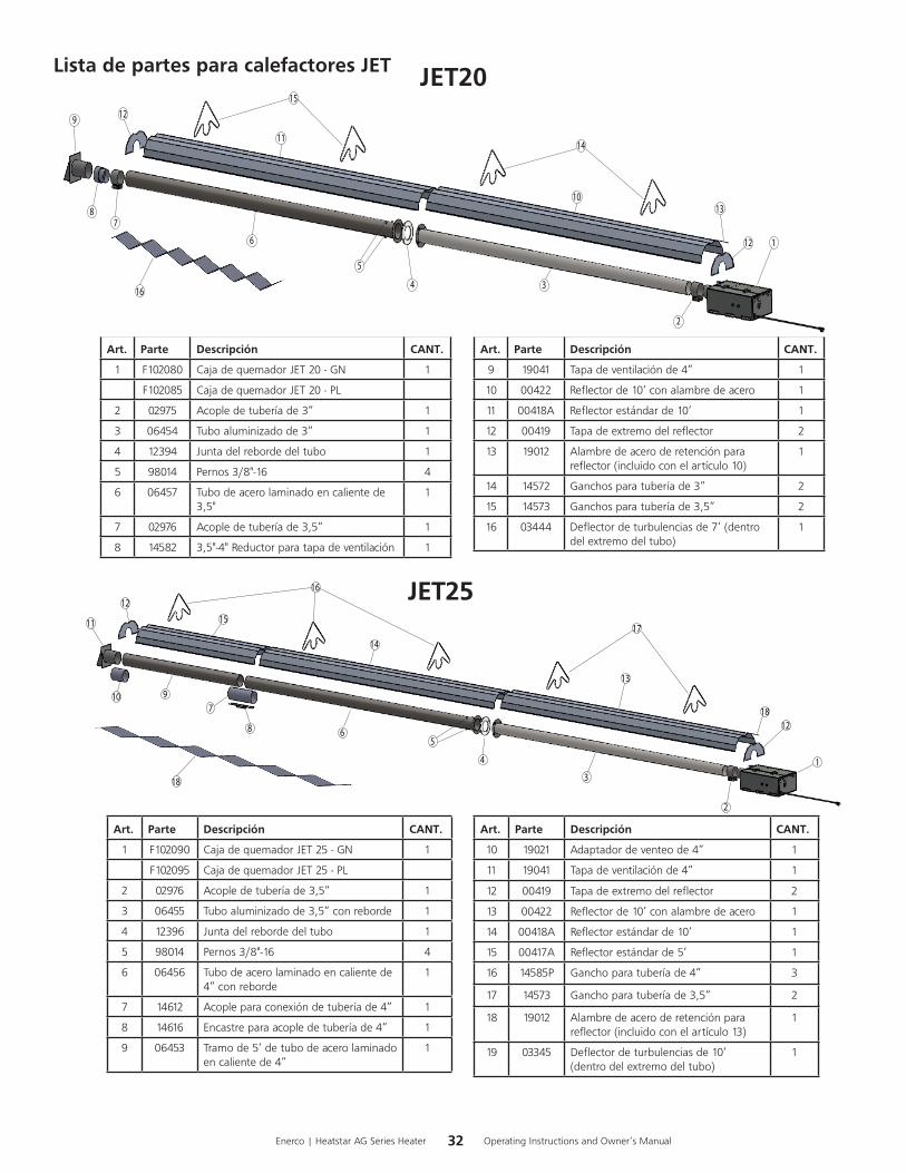
Lista de partes para calefactores JET
Art. Parte Descripción CANT.
1 F102090 CajadequemadorJET25-GN 1
F102095 CajadequemadorJET25-PL
2 02976 Acopledetuberíade3,5” 1
3 06455 Tuboaluminizadode3,5”conreborde 1
4 12396 Juntadelrebordedeltubo 1
5 98014 Pernos3/8"-16 4
6 06456 Tubodeacerolaminadoencalientede4”conreborde
1
7 14612 Acopleparaconexióndetuberíade4” 1
8 14616 Encastreparaacopledetuberíade4” 1
9 06453 Tramode5’detubodeacerolaminadoencalientede4”
1
Art. Parte Descripción CANT.
1 F102080 CajadequemadorJET20-GN 1
F102085 CajadequemadorJET20-PL
2 02975 Acopledetuberíade3” 1
3 06454 Tuboaluminizadode3” 1
4 12394 Juntadelrebordedeltubo 1
5 98014 Pernos3/8"-16 4
6 06457 Tubodeacerolaminadoencalientede3,5"
1
7 02976 Acopledetuberíade3,5” 1
8 14582 3,5"-4"Reductorparatapadeventilación 1
Art. Parte Descripción CANT.
10 19021 Adaptadordeventeode4” 1
11 19041 Tapadeventilaciónde4” 1
12 00419 Tapadeextremodelreflector 2
13 00422 Reflectorde10’conalambredeacero 1
14 00418A Reflectorestándarde10’ 1
15 00417A Reflectorestándarde5’ 1
16 14585P Ganchoparatuberíade4” 3
17 14573 Ganchoparatuberíade3,5” 2
18 19012 Alambredeaceroderetenciónparareflector(incluidoconelartículo13)
1
19 03345 Deflectordeturbulenciasde10’(dentrodelextremodeltubo)
1
JET20
Art. Parte Descripción CANT.
9 19041 Tapadeventilaciónde4” 1
10 00422 Reflectorde10’conalambredeacero 1
11 00418A Reflectorestándarde10’ 1
12 00419 Tapadeextremodelreflector 2
13 19012 Alambredeaceroderetenciónparareflector(incluidoconelartículo10)
1
14 14572 Ganchosparatuberíade3” 2
15 14573 Ganchosparatuberíade3,5” 2
16 03444 Deflectordeturbulenciasde7’(dentrodelextremodeltubo)
1
1
3
6
4
5
2
78
9
10
11
12
13
14
1512
16
JET25
33 Operating Instructions and Owner’s ManualEnerco | Heatstar AG Series Heater
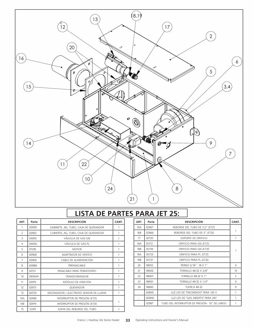
ART. Parte DESCRIPCIÓN CANT.
1 02999 GABINETE,AG,TUBO,CAJADEQUEMADOR 1
2 02963 CUBIERTA,AG,TUBO,CAJADEQUEMADOR 1
3 00055 VÁLVULADEGASGN 1
4 00056 VÁLVULADEGASPL 1
5 07376 MOTOR 1
6 02968 ADAPTADORDEVENTEO 1
7 02964 CABLEDEALIMENTACIÓN 1
8 60889 PRENSACABLE 1
9 02721 PASACABLEPARATERMOSTATO 1
10 08364A TRANSFORMADOR 1
11 02970 MÓDULODEIGNICIÓN 1
12 02973 QUEMADOR 1
13 60729 ENCENDEDOR/ELECTRODOSENSORDELLAMA 1
14A 02969 INTERRUPTORDEPRESIÓNJET251
14B 02979 INTERRUPTORDEPRESIÓNJET20
15 12397 JUNTADELREBORDEDELTUBO 1
ART. Parte DESCRIPCIÓN CANT.
16A 02967 REBORDEDELTUBODE3,5“JET251
16B 02966 REBORDEDELTUBODE3“JET20
17 02720 SOPORTEDEORIFICIO 1
18A 05712 ORIFICIOPARAGNJET25
118B 05718 ORIFICIOPARAGNJET20
19A 05733 ORIFICIOPARAPLJET25
19B 05737 ORIFICIOPARAPLJET20
20 98012 PERNO5/16"-18X1" 4
21 98902 TORNILLO#8-32X3/8” 10
22 98907 TORNILLO#8-32X1” 2
23 98901 TORNILLO#8-32X1/4” 4
24 98692 TUERCA#8-32 9
- 60845 LUZLEDDE"ENCENDIDO"PARA120V 1
- 60846 LUZLEDDE"GASABIERTO"PARA24V 1
- 02987 TUBODELINTERRUPTORDEPRESIÓN-10”DELARGO 1
LISTA DE PARTES PARA JET 25:
1
2
3,4
5
6
7
9
8
10
11
1213
14
16
15
17
18,19
20
24
21
22
C

34Enerco | Heatstar AG Series Heater Operating Instructions and Owner’s Manual
ADVERTENCIA:USESOLAMENTEPARTESDEREPUESTODELFABRICANTE.ELUSODECUALQUIEROTRAPARTEPODRÍACAUSARHERIDASOLAMUERTE.LASPARTESDEREPUESTOES-TÁNDISPONIBLESÚNICAMENTEENLAFÁBRICAYDEBENSERINSTALADASPORUNAAGENCIADESERVICIOCALIFICADA.
POR INFORMACIÓN ACERCA DE REPARACIONES O PARTES:
Llameasutécnicolocaldecalefacciónodistribuidor:
POR INFORMACIÓN ADICIONAL:
Porfavorllamesincargoal866-447-2194•www.heatstarbyenerco.comNuestrohorariodetrabajoesde08:00a.m.AMa5:00PM,delunesaviernes,horadeleste.Tengaamanosunúmerodemodelo,númerodeserieyfechadecompra.
GARANTÍA LIMITADA
Lacompañíagarantizaqueesteproductoestarálibredeimperfeccionesmaterialesydefabricación,bajocondicionesdeusonormalesyadecuadasdeacuerdoconlasinstruccionesdelaCompañía,porunperíodode1añoparalacajayde2añosparaparalastuberías,apartirdelafechadeentregaalcomprador.
LaCompañía,segúndecida,repararáoreemplazarálosproductosqueelcompradordevuelvaalafábrica,conlosgastosdeenvíopreviamentepagadosdentrodelmencionadoperíododegarantía,yquelaCompañíadeterminequepresentanimperfeccionesmaterialesodefabricación.
Sialgunadelaspartesestádañadaosilefaltaalguna,llameanuestroDepartamentodeasistenciaalclienteal866-447-2194.
DirijatodoslosreclamosdegarantíaalDepartamentodeasistenciaalcliente,Heatstar,Inc.,4560W.160THST.,CLEVELAND,OHIO44135.Incluyasunombre,direcciónynúmerotelefónicoensucomunicacióneincluyalosdetallesrelacionadosconelreclamo.Además,infórmenoslafechadelacomprayelnombreydireccióndelproveedordequienadquiriónuestroproducto.
LoanteriordescribelasresponsabilidadesdelaCompañíaentodasuextensión.Nohayotrasgarantías,niexplícitasniimplícitas.Específicamente,nohaygarantíasacercadelaadecuaciónparaunpropósitoparticularynohaygarantíasdecomerciabilidad.EnningúncasolaCompañíaseráresponsablepordemorascausadasporimperfecciones,pordañosconsecuentes,niporningúnotrocargodegastosdeningunanaturalezarealizadosinsuconsentimientoescrito.Elcostodereparaciónoreemplazoserálaúnicacompensaciónporcualquierincumplimientodelagarantía.Nohaygarantíanisederivarágarantíaimplícitaalgunadelprocesodecomercializaciónnidelasprácticascomercialescomunes.Estagarantíanoseráválidaparaproductosquehayansidoreparadosoalteradosfueradelafábricaencualquiersentidoqueanuestrocriterioafectesuestadoofuncionamiento.
Algunosestadosnopermitenlaexclusiónolimitacióndedañosincidentalesniconsecuentes,asíquelalimitaciónoexclusiónanteriorpuedenotenervalidezensucaso.EstaGarantíaleotorgaderechoslegalesespecíficos,yustedpuedetenerotrosderechosquevaríandeunestadoaotro.
Heatstar,Inc.,4560W.160THST.,CLEVELAND,OHIO44135•866-447-2194©2019,Heatstar,Inc.Todoslosderechosreservados
Heatstar,Inc.sereservaelderechodehacercambiosencualquiermomento,sinprevioaviso,enloscolores,especificaciones,accesorios,materialesymodelos.
INSTRUCCIONES DE USO Y MANUAL DEL USUARIO
MODELO
SDE120V
by ENERCO
JET20JET25