read first! - gsimfab
TRANSCRIPT
1

2
READ FIRST!
PLEASE READ THROUGH ALL OF THE INSTRUCTIONS AND ENSURE THAT YOU UNDERSTAND THEM. BE SURE THAT YOU HAVE ALL THE REQUIRED GSI COMPONENTS, BASIC TOOLS, AND SKILLS.
ALL DIMENSIONS ARE IN INCHES!
THIS KIT IS USE AT YOUR OWN RISK!
GENERAL MOTORS publishes a Chassis Best Practices Manual for their GM Upfitter program, openly available on their website. By no means are the modifications covered by this manual endorsed by GM in any way, nor was the latest revision written with a ’63-’72 frame shortening in mind. However, we
attempted to follow their “Chassis -Best Practices-2015: Extending wheelbase/moving axle” Rev 2/08/2015 as best as possible in attempt to provide the safest product possible.
CUTTING
THIS KIT REQUIRES SIGNIFICANT CUTTING TO THE EXISTING FRAME. AIR HAMMERS, ABRASIVE CUT-OFF WHEELS, AND RECIPROCATING POWER SAWS (SAWZALL) ARE RECOMMENDED TOOLS. THERE SHOULD BE NO NEED FOR ANY MODIFICATION TO THE GSI SUPPLIED PARTS. ****SEE PROTOTYPE NOTICE***
WELDING
THIS KIT REQUIRES WELDING TO THE FRAME. MIG (GMAW) WELDING PROCESS WITH A SUITABLE MIX GAS AND ER70S2 WIRE IS RECOMMENDED. DETAILED INSTRUCTIONS REGARDING HOW THE FRAME IS TO BE WELDED IS BASED ON GM UPFITTER RECOMMENDED PRACTICES.
NOTICE OF PROTOTYPE
This kit is a prototype. The suspension is identical to that of our other kits and should function. The method of welding the frame is UNTESTED and all other
secondary brackets, mounts, crossmembers have not been designed yet.

3
1. You will want to remove the cab at the least before starting. The frame is going to be cut in a location forward of
the rear body mount.
2. Where to cut:
The hole identified in the above picture is located 4 inches behind the rear body mount. The
hole was originally a frame gauge hole, used by GM and repair shops to position the frame. As far as we know
this hole exists on all frames. There is also another hole 19 inches in front of the rear body mount (all
dimensions are from hole center). Use the holes about the rear body mount to position the cut as shown in
figure 2. The idea is the body mount will be in the same place.
Figure 1 FRAME GAGE HOLES (PASSENGER SIDE SHOWN)
Figure 2 CUT LOCATION SHOWN BY “-B- CUT LINE” WITH MULTIPLE REFERENCE DIMENSIONS. (DRIVER SIDE SHOWN)

4
Figure 4 HOW TO WELD THE FRAME
3. It is critical that the cuts are made vertical (perpendicular) with respect to the frame. If these are cut is at an
angle your truck frame will look bent! Both Driver and Passenger side frame rails will need to be cut in the same
location!
4. Clean the frame near the cut to BARE METAL at the least for welding. We suggest a wire wheel. The cleaner the
rest of the frame is the better chance you will have of making sure everything is lined up straight.
5. Once clean physically scribe/draw the cut line on the frame and DOUBLE CHECK that it is correct. Repeat this
step at least twice.
6. Support both sides of the frame to be cut and make the cut. Remove the back of the old frame.
7. Grind and cut the edges of the frame for the best possible fit with the GSI Backhalf. Both the forward portion of
the frame and the GSI Backhalf will need to have a 30° degree, ½ the thickness (.1875/2=.093=3/32) bevel put
into both parts for welding.
8. Position the forward frame and back half as best as possible. Fixture and clamp the GSI Backhalf to insure
correct alignment. Check for square and level.
9. Once proper alignment is confirmed, tack runoff blocks as shown below to help ensure position and prevent
weld burnout on the edge.
10. Butt weld the outside of the joint with a single pass-vertical up first. Then but weld inside surface of the frame
should also be done with a single pass.
Figure 3 BUTT WELD EDGE PREP

5
11. Remove runoff blocks and grind the outside of the joint smooth. The outside surface of the frame weldment
must be as smooth as the rest of the frame to allow flush fit for reinforcement attachment. Make sure that grind
marks are parallel to the length of the frame.
12. Secure the L-shaped reinforcement with clamps to the outside of the frame rail. There should be no visible gaps
between the frame rail and the reinforcement other than at the bend.
13. Fillet weld the reinforcement to the frame rail, using a stitch weld technique. Weld as shown in figure below.
Leave corners, bends and radii free to flex. Welding in these locations creates stress risers that can often lead to
cracks in the weld.
NOTE
GM RECOMMENDS DO NOT WELD ON THE LOWER FLANGE OF THE FRAME, EITHER ON THE FLANGE OR AT THE EDGE
Figure 6: 8 WELDS PER SIDE AS SHOWN
Figure 5 FRAME REINFORCEMENT. ONE PER RAIL
6
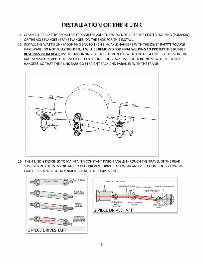
14. CLEAN ALL BRACKETRY FROM THE 3” DIAMETER AXLE TUBES. DO NOT ALTER THE CENTER HOUSING (PUMPKIN),
OR THE AXLE FLANGES (BRAKE FLANGES) ON THE ENDS FOR THIS INSTALL.
15. INSTALL THE WATT’S LINK MOUNTING BAR TO THE 4 LINK AXLE HANGERS WITH THE Ø5/8” WATT’S TO AXLE
HARDWARE. DO NOT FULLY TIGHTEN, IT WILL BE REMOVED FOR FINAL WELDING TO PROTECT THE RUBBER
BUSHINGS FROM HEAT. USE THE MOUNTING BAR TO POSITION THE WIDTH OF THE 4 LINK BRACKETS ON THE
AXLE SYMMETRIC ABOUT THE VEHICLES CENTERLINE. THE BRACKETS SHOULD BE INLINE WITH THE 4 LINK
HANGERS, SO THAT THE 4 LINK BARS GO STRAIGHT BACK AND PARALLEL WITH THE FRAME.
16. THE 4 LINK IS DESIGNED TO MAINTAIN A CONSTANT PINION ANGLE THROUGH THE TRAVEL OF THE REAR
SUSPENSION. THIS IS IMPORTANT TO HELP PREVENT DRIVESHAFT WEAR AND VIBRATION. THE FOLLOWING
GRAPHICS SHOW IDEAL ALIGNMENT OF ALL THE COMPONENTS.
1 PIECE DRIVESHAFT
driDREIDRIVESHAFT
2 PIECE DRIVESHAFT
DRIVESHAFT

7
IT IS OFTEN RECOMMENDED THAT THE “REAR WORKING ANGLE” OR “PINION ANGLE” IS PARALLEL TO THE
TRANSMISSION TAIL SHAFT (OR FRONT DRIVE SHAFT FOR 2 PIECE SHAFTS). THIS IS OFTEN 3° TO 4° (DEGREES).
WITH THE AXLE SET AT THE PROPER ANGLE, PLACE A LEVEL ON THE LOWER AIRBAG MOUNT PLATE AND MAKE
IT PARALLEL TO THE GROUND.
17. WHEN YOU ARE SURE OF POSITION AND PINION ANGLE, BE SURE TO CLEAN THE AREA ON THE AXLE TO BE
WELDED TO BARE METAL AND TACK WELD THE AXLE BRACKETS ON IN POSITION.
NOTES
DO NOT FULLY WELD AXLE MOUNTS. TACK FIRST, AND CONTINUE MOCKING UP 4 LINK BARS, SHOCKS, ETC. FULLY WELD ONLY WHEN SURE EVERYTHING WORKS! GRINDING OFF FULLY WELDED AXLE BRACKETS IS NOT FUN.
REMOVE WATT’S LINK MOUNT SO THAT ITS URETHANE BUSHINGS DO NOT MELT DURING FINAL WELDING.
AGAIN ALLOW TO COMPLETELY AIR COOL.

8
18. BOLT THE SHOCKS TO THE UPPER SHOCK BUNGS USING Ø1/2” SHOCK HARDWARE, USE A SPLIT LOCK WASHER!
19. ADJUST YOUR 4 LINK BARS WITH ROD ENDS INSTALLED AS FOLLOWS:
a. UPPER 4 LINK BAR SHOULD MEASURE 23.4” INCHES BETWEEN CENTER OF THE ROD ENDS
b. LOWER 4 LINK BAR SHOULD MEASURE 26.1” INCHES BETWEEN CENTER OF THE ROD ENDS
NOTE:
DEVIATION FROM THE NUMBERS IN a AND b IS OKAY AS LONG AS IT WORKS. EVERY TRUCK INSTALL WILL BE DIFFERENT. THESE ARE THE “DESIGN” LENGTHS. TRY TO BE AS CLOSE TO THESE NUMBERS AS POSSIBLE.
20. INSTALL Ø5/8 4 LINK HARDWARE INTO ALL OF THE ROD ENDS, FOR THE 4 LINK HANGERS AND THE AXLE
BRACKETS. NOTE THE BOLT CLOSEST TO THE SHOCK HAS ITS HEAD TOWARD THE SHOCK FOR CLEARANCE.
21. THE LOWER AXLE BRACKETS USE THE GSI SUPER SHOCK BOLT HARDWARE KIT. IT IS A CUSTOM
MANUFACTURED GRADE 8 EQUIVALENT DOUBLE ENDED BOLT. THE Ø5/8 PORTION IS DESIGNED TO HOLD THE
LOWER 4 LINK BAR ROD ENDS TO THE AXLE, WHILE THE OPPOSITE Ø1/2” PORTION IS DESIGNED TO SECURE THE
LOWER EYE OF THE SHOCK. USE THE SUPPLIED WASHERS AND NYLOCK NUTS JUST AS YOU WOULD WITH ANY
BOLT.

9
22. REINSTALL THE WATT’S LINK MOUNTING BAR TO THE AXLE BRACKETS ONCE COOL.
23. CHECK THAT THE TWO LINKS THAT GO FROM THE CENTER LINK TO THE NOTCHES ARE 12-5/16” BETWEEN
CENTER OF THE FK ROD ENDS. LIKE THE NOTE IN STEP 18, THESE ARE THE “DESIGN” LENGTHS. TRY TO BE AS
CLOSE TO THESE NUMBERS AS POSSIBLE.
24. INSTALL THE WATT’S LINK COMPONENTS PER THE DIAGRAM BELOW, USING THE WATT’S LINK HARDWARE.
HIGH MISALIGNMENT SPACERS ARE USED ON THE FRAME CLEVIS ENDS.
25. WATT’S LINK CLEVIS DETAIL SHOWING HIGH MISALIGNMENT SPACERS INSTALLED.
WATT’S LINK CENTER DETAIL. NO HIGH MISALIGNMENT SPACERS ON THE CENTER FK ROD ENDS. NOTE THAT ON BOTH
SIDES OF THE PRESSED IN BEARINGS THERE ARE THIN STAINLESS WASHERS THAT MUST BE BETWEEN THE BOLT HEAD
AND THE BEARING, AND BETWEEN THE BEARING AND THE WATT’S LINK MOUNT.
CENTER LINK MOVEMENT!
WITHOUT THE TWO STAINLESS WASHERS THE BEARINGS WILL NOT WORK! IF THE CENTER Ø5/8 BOLT IS TIGHTENED TOO MUCH IT WILL “FREEZE” THE BEARINGS. DO NOT OVERTIGHTEN.
THE CENTER LINK SHOULD BE ABLE TO FREELY MOVE ON THE BEARINGS.
NOTE:
CYCLE SUSPENSION TO ENSURE ALL LINKAGE WORKS PROPERLY TOGETHER AND FULLY WELD REMAINING TACKED PARTS.

10
26. INSTALL AIRBAGS USING Ø3/8 AIRBAG HARDWARE USE THE SPLIT LOCK WASHERS. 2 ON TOP AND 1 ON
BOTTOM. YOU WILL NEED TO INSTALL AIR FITTINGS AS NEEDED FOR YOUR AIR SYSTEM.
27. FINAL CHECK:
a. DOUBLE CHECK THAT ALL FASTENERS ARE TIGHT.
b. ENSURE THE REAR SUSPENSION FREELY MOVES THROUGH ITS ENTIRE TRAVEL.
28. FIRST DRIVE:
a. USE EXTREME CAUTION THE FIRST TIME YOU DRIVE.
b. PLAN THE DRIVE. STAY AWAY FROM BUSY ROADS AND PLACES WHERE IT IS NOT EASY TO PULL OVER
AND PERFORM MAINTENANCE. DO NOT GO ALONE. HAVE A CHASE CAR. STAY CLOSE.
c. LISTEN FOR ANY UNUSUAL SOUNDS.
d. PERIODICALLY STOP AND INSPECT THAT ALL HARDWARE IS STILL TIGHT.
ENJOY!