reactor models - marmara Üniversitesi bilişim merkezimimoza.marmara.edu.tr/~zehra.can/chem209/04....
TRANSCRIPT
1
Reactor Models

REACTOR
A reactor is the place where the desired reaction takes place that is, the removal of a selected contaminant.
Containers, vessels or tanks in which chemical or biological reactions are carried out.
2
Source: Fundamentals of Water Treatment: Unit Processes
Physical, Chemical, and Biological

3
MATHEMATICS OF REACTORS
Reactor mathematics is based upon two principles:
(1) Materials balance and
(2) reaction kinetics.
Materials Balance: Concept The basic idea of a reactor model is quite simple and is embodied in the following equation.

(mass balance )
Materials Balance
4
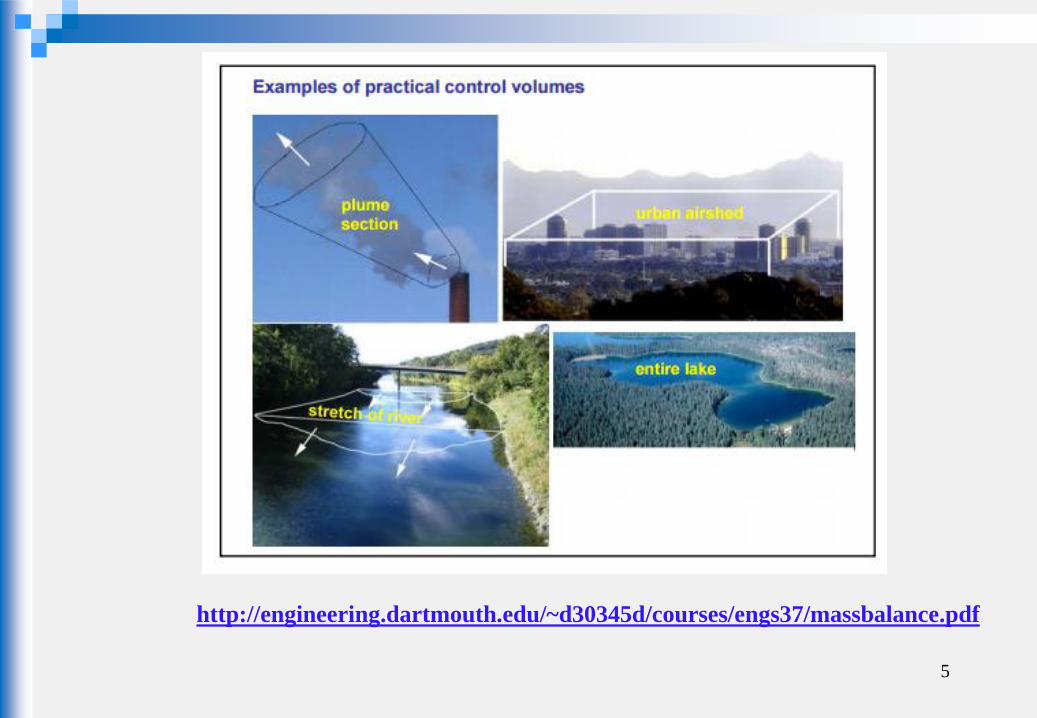
The first step involved in preparing a mass balance is to define
the system boundary so that all the flows of mass into and out
of the system boundary can be identified.
Source: Fundamentals of Water Treatment: Unit Processes
Physical, Chemical, and Biological
5
http://engineering.dartmouth.edu/~d30345d/courses/engs37/massbalance.pdf

Materials Balance quantitative description of all materials
(mass balance ) that enter, leave and accumulate in a system with defined boundaries.
based on the law of conservation of mass (mass is neither created nor destroyed)
is developed on a chosen control volume.
Materials Balance
6
7
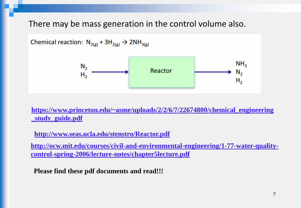
https://www.princeton.edu/~asme/uploads/2/2/6/7/22674800/chemical_engineering
_study_guide.pdf
There may be mass generation in the control volume also.
http://www.seas.ucla.edu/stenstro/Reactor.pdf
http://ocw.mit.edu/courses/civil-and-environmental-engineering/1-77-water-quality-
control-spring-2006/lecture-notes/chapter5lecture.pdf
Please find these pdf documents and read!!!
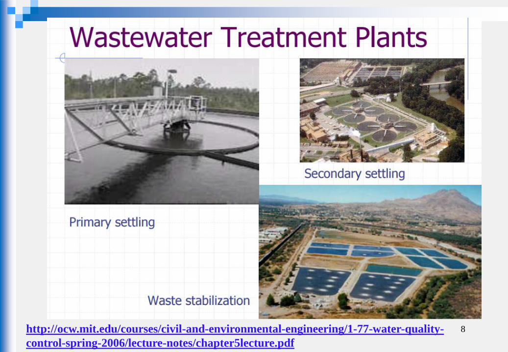
8 http://ocw.mit.edu/courses/civil-and-environmental-engineering/1-77-water-quality-
control-spring-2006/lecture-notes/chapter5lecture.pdf
9
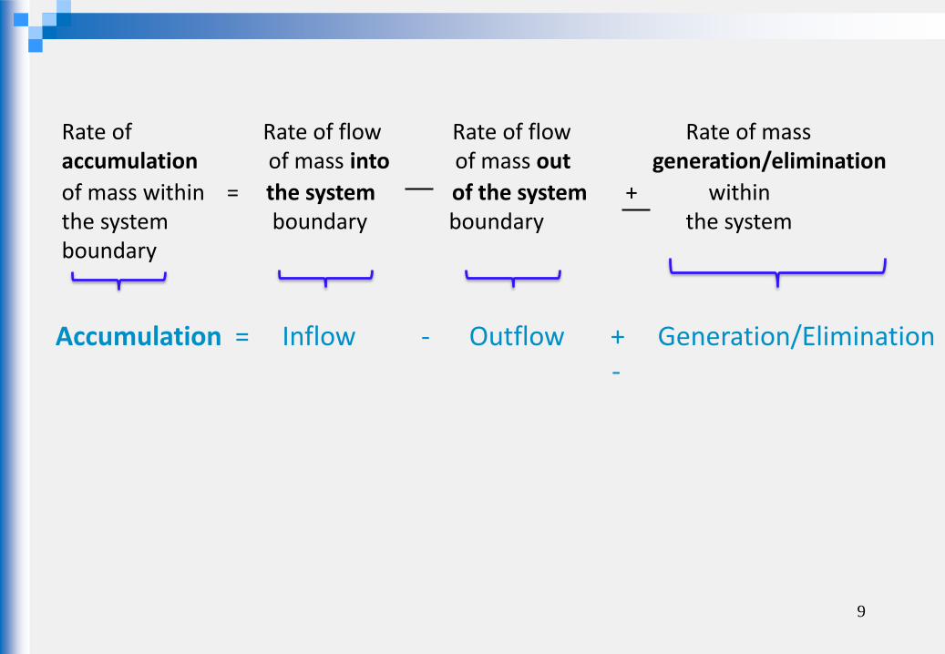
Rate of Rate of flow Rate of flow Rate of mass accumulation of mass into of mass out generation/elimination
of mass within = the system of the system + within the system boundary boundary the system boundary
Accumulation = Inflow - Outflow + Generation/Elimination -

dt
dC
Symbolic Representation:
rate of change of reactant concentration within the reactor (g / m3 sec)
volume of the reactor, m3
Q = flow into and out of the reactor ( m3 /sec)
C0=concentration of reactant in the reactor and effluent (g/ m3 )
r = rate of generation (g/ m3 sec)
Accumulation = Inflow - Outflow + Generation/Elimination
Generation/Elimination term. can be “+” or “-“ [Most of the materials of interest disappear and therefore generation term is “-“ in most cases.]
Accumulation = Inflow - Outflow + Generation/Elimination
10
∀-(∀ rQC)QCdt
dCo
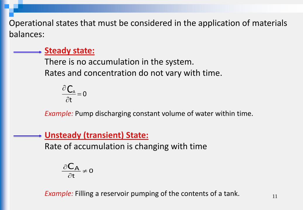
Operational states that must be considered in the application of materials balances:
Steady state: There is no accumulation in the system. Rates and concentration do not vary with time.
0t
CA
Example: Pump discharging constant volume of water within time.
Unsteady (transient) State: Rate of accumulation is changing with time
0tAC
Example: Filling a reservoir pumping of the contents of a tank. 11

12
Types of reactors

REACTOR MODELS
13
Source: MWH’s Principles of Water Treatment , Third Edition, Ch4 Kerry J. Howe, David W. Hand, John C. Crittenden, R. Rhodes Trussel and George Tchobanoglous, 2012 John Wiley & Sons, Inc.
Common reactor configurations include (a) completely mixed batch reactors, (b) completely mixed flow reactors (CMFRs), and (3) plug flow reactors (PFRs).
REACTOR MODELS
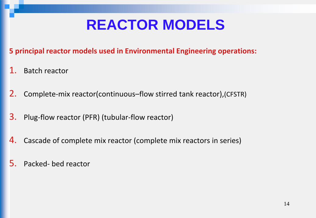
5 principal reactor models used in Environmental Engineering operations:
1. Batch reactor
2. Complete-mix reactor(continuous–flow stirred tank reactor),(CFSTR)
3. Plug-flow reactor (PFR) (tubular-flow reactor)
4. Cascade of complete mix reactor (complete mix reactors in series)
5. Packed- bed reactor
14
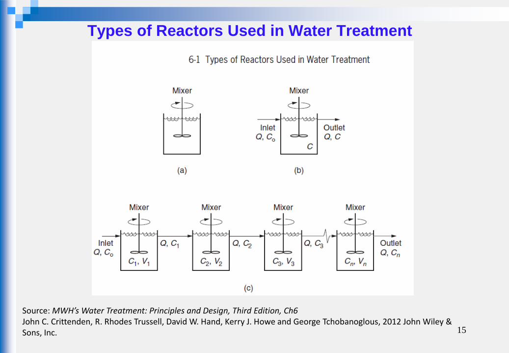
Types of Reactors Used in Water Treatment
15
Source: MWH’s Water Treatment: Principles and Design, Third Edition, Ch6 John C. Crittenden, R. Rhodes Trussell, David W. Hand, Kerry J. Howe and George Tchobanoglous, 2012 John Wiley & Sons, Inc.

16
Source: MWH’s Water Treatment: Principles and Design, Third Edition , Ch6 John C. Crittenden, R. Rhodes Trussell, David W. Hand, Kerry J. Howe and George Tchobanoglous, 2012 John Wiley & Sons, Inc.

Applications:
Is a non-continuous and perfectly mixed closed vessel where a reaction takes place.
A common use of batch reactors in laboratories is to determine the reaction
equation and rate constant for a chemical reaction.
The kinetic information determined in a batch reactor can be used to design other types of reactors and full-scale treatment facilities.
17
BATCH REACTORS
The simplest reactor type Flow is neither entering nor leaving the reactor The liquid contents are mixed completely and uniformly
Ref: http://www.water-msc.org/e-learning/file.php/40/moddata/scorm/203/Lesson%204_04.htm

18
Batch reactors have no inputs or outputs.
19
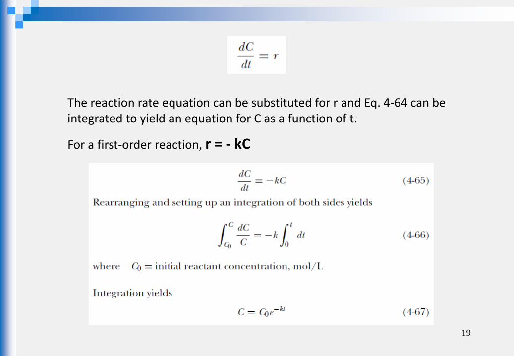
The reaction rate equation can be substituted for r and Eq. 4-64 can be integrated to yield an equation for C as a function of t.
For a first-order reaction, r = - kC

20
For a second-order reaction, r = - kC2
rVQCQCdt
dCo
oC,Q
C.
C,Q
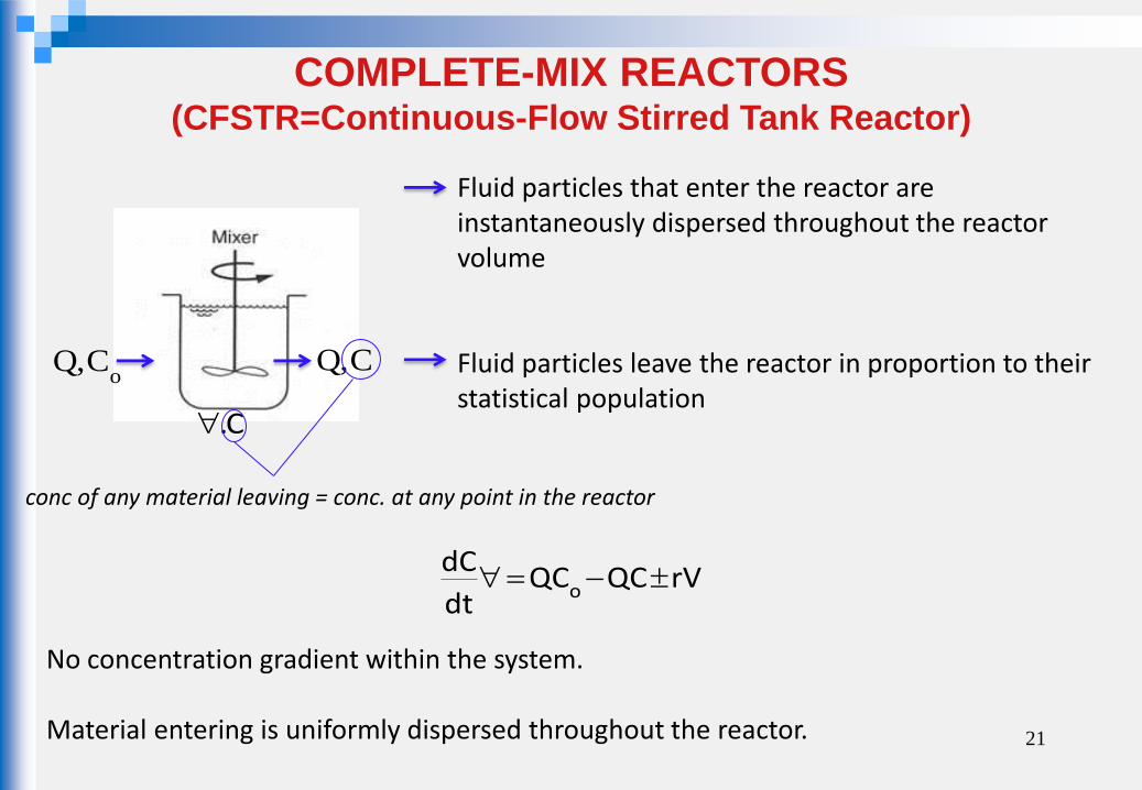
conc of any material leaving = conc. at any point in the reactor
21
Fluid particles that enter the reactor are instantaneously dispersed throughout the reactor volume Fluid particles leave the reactor in proportion to their statistical population
COMPLETE-MIX REACTORS (CFSTR=Continuous-Flow Stirred Tank Reactor)
No concentration gradient within the system. Material entering is uniformly dispersed throughout the reactor.
22
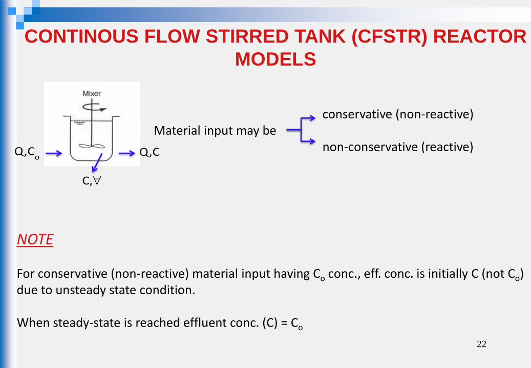
CONTINOUS FLOW STIRRED TANK (CFSTR) REACTOR
MODELS
NOTE For conservative (non-reactive) material input having Co conc., eff. conc. is initially C (not Co) due to unsteady state condition. When steady-state is reached effluent conc. (C) = Co
conservative (non-reactive) Material input may be non-conservative (reactive)
oC,Q
,C
C,Q

23
Some reactor analyses are conducted with conservative (or nonreactive) constituents.
It may seem that conservative chemicals would be of little interest in reactor analysis.
However, they provide a mechanism for understanding the hydraulic characteristics of a reactor.
Since conservative constituents do not react, they flow with the water and stay in a reactor as long as the water stays in the reactor.
Thus, a curve of effluent concentration of a conservative constituent reveals the residence time distribution of the water in the reactor.
Conservative constituents are commonly called tracers, and tests to determine the residence time distribution of a reactor are called tracer tests.
Conservative (non-reactive) = Tracer tests
Source: MWH’s Principles of Water Treatment , Third Edition, Ch4 Kerry J. Howe, David W. Hand, John C. Crittenden, R. Rhodes Trussel and George Tchobanoglous, 2012 John Wiley & Sons, Inc.

24
→ Tracers (dyes, electrolytes, radioactive isotopes) are used to characterize the degree of mixing.
→ must be conservative
does not participate in any reaction it is not adsorbed or absorbed by reactor or its contents → are assumed to be moved about in the same manner as the water molecules their flow pattern will mimic liquid flow pattern.
Tracers
25
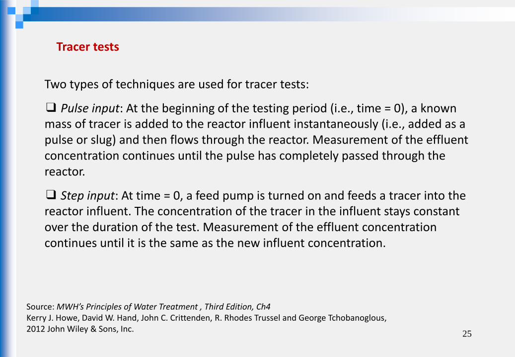
Two types of techniques are used for tracer tests:
❑ Pulse input: At the beginning of the testing period (i.e., time = 0), a known mass of tracer is added to the reactor influent instantaneously (i.e., added as a pulse or slug) and then flows through the reactor. Measurement of the effluent concentration continues until the pulse has completely passed through the reactor.
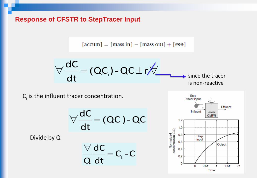
❑ Step input: At time = 0, a feed pump is turned on and feeds a tracer into the reactor influent. The concentration of the tracer in the influent stays constant over the duration of the test. Measurement of the effluent concentration continues until it is the same as the new influent concentration.
Tracer tests
Source: MWH’s Principles of Water Treatment , Third Edition, Ch4 Kerry J. Howe, David W. Hand, John C. Crittenden, R. Rhodes Trussel and George Tchobanoglous, 2012 John Wiley & Sons, Inc.

26
Tracer tests
Source: MWH’s Principles of Water Treatment , Third Edition, Ch4 Kerry J. Howe, David W. Hand, John C. Crittenden, R. Rhodes Trussel and George Tchobanoglous, 2012 John Wiley & Sons, Inc.

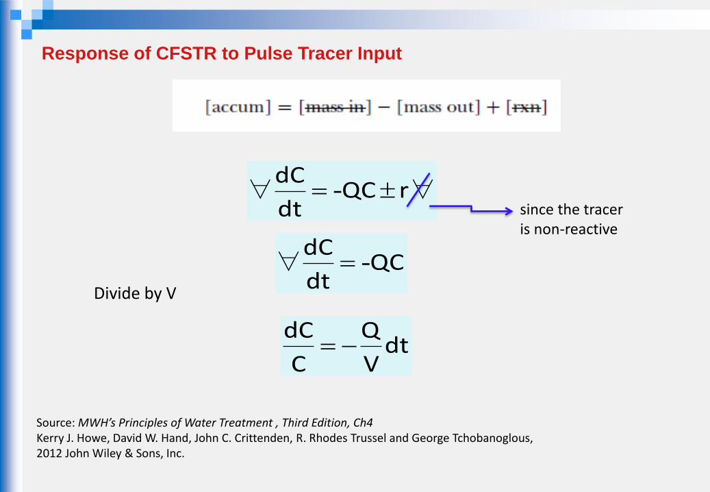
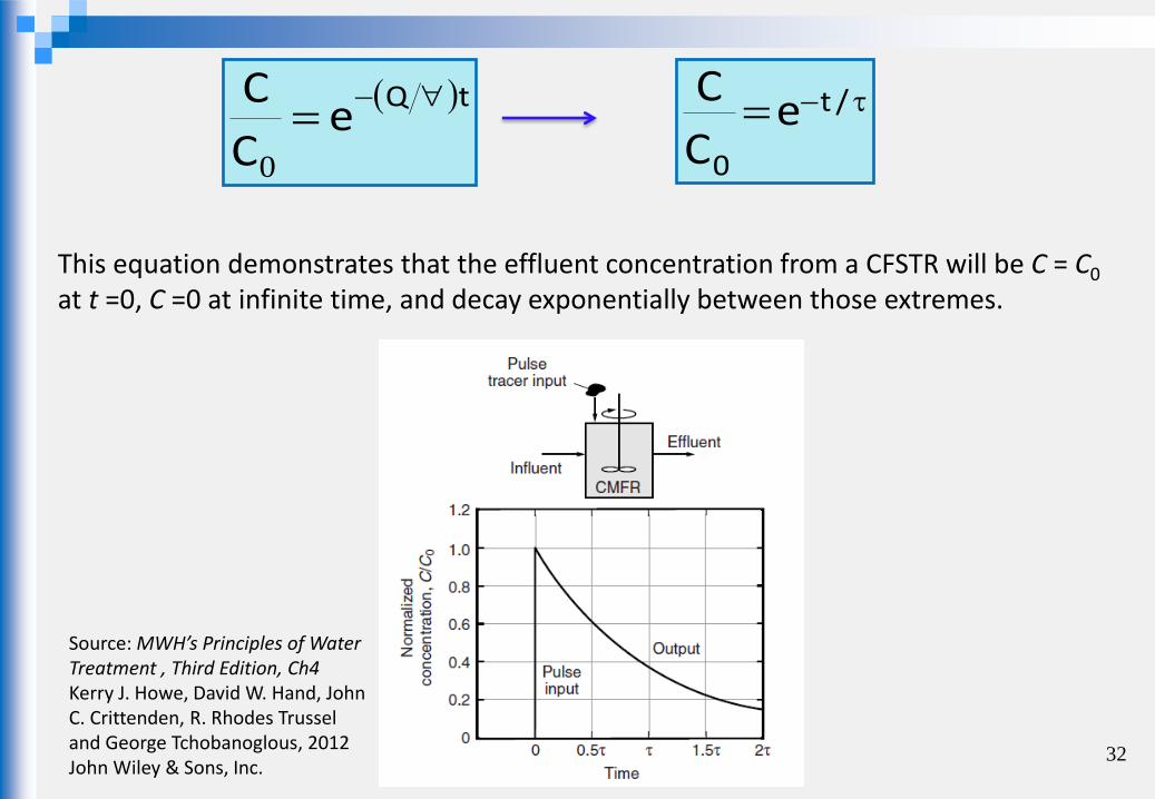
Response of CFSTR to Pulse Tracer Input
When a pulse input is introduced into a CFSTR, the effluent tracer concentration instantly reaches a maximum as the tracer is uniformly distributed throughout the reactor.
As clean water (containing no tracer) continues to enter the reactor after time = 0, the tracer gradually dissipates in an exponential manner as the tracer material leaves the effluent.
The exponential shape of the tracer curve can be demonstrated using a mass balance analysis of a CMFR.
∀-∀ rQCdt
dC
QCdt
dC-∀
Divide by V
dtV
Q
C
dC
since the tracer is non-reactive
Response of CFSTR to Pulse Tracer Input
Source: MWH’s Principles of Water Treatment , Third Edition, Ch4 Kerry J. Howe, David W. Hand, John C. Crittenden, R. Rhodes Trussel and George Tchobanoglous, 2012 John Wiley & Sons, Inc.
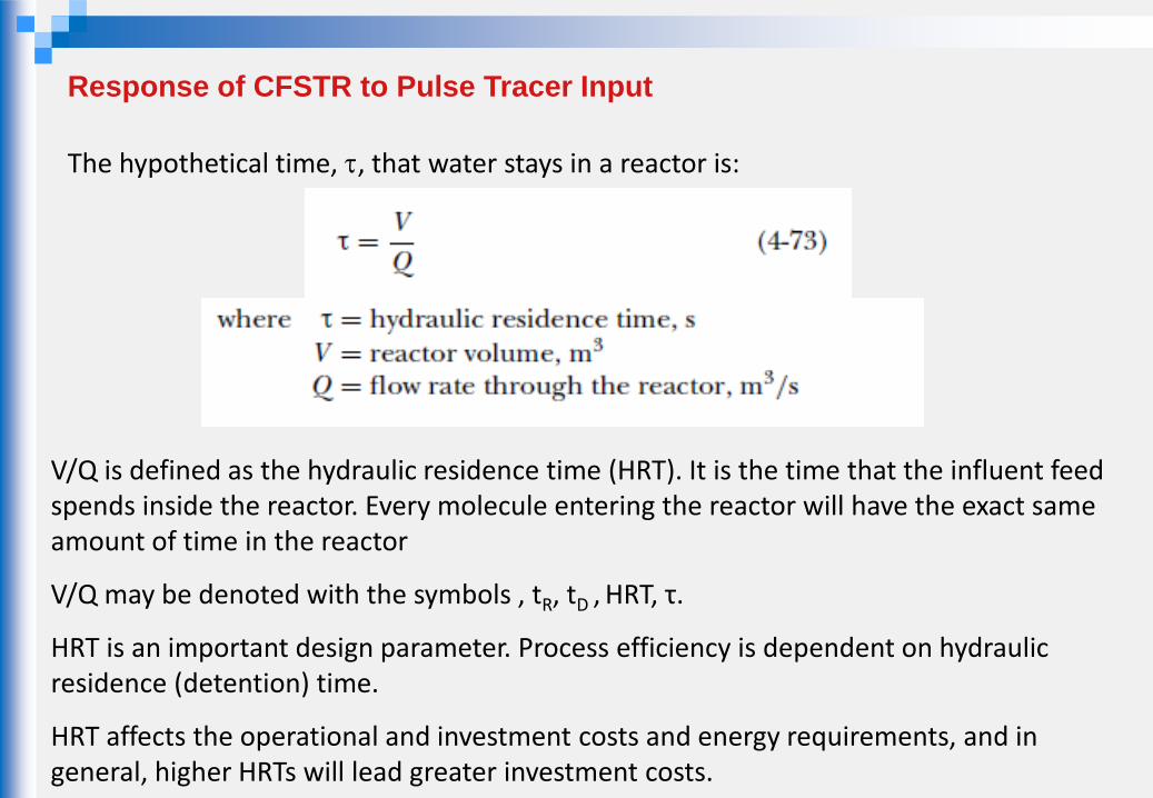
Response of CFSTR to Pulse Tracer Input
The hypothetical time, , that water stays in a reactor is:
V/Q is defined as the hydraulic residence time (HRT). It is the time that the influent feed spends inside the reactor. Every molecule entering the reactor will have the exact same amount of time in the reactor
V/Q may be denoted with the symbols , tR, tD , HRT, τ.
HRT is an important design parameter. Process efficiency is dependent on hydraulic residence (detention) time.
HRT affects the operational and investment costs and energy requirements, and in general, higher HRTs will lead greater investment costs.
30
t
t
dtV
QC
C C
dC
o 0
dtV
Q
C
dC
tV
QLnCLnC
0
tV
Q
C
CLn
o
tV
Q
C
CLn
o
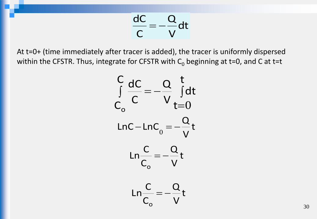
At t=0+ (time immediately after tracer is added), the tracer is uniformly dispersed within the CFSTR. Thus, integrate for CFSTR with C0 beginning at t=0, and C at t=t
tQe
C
C
0
31
/t
0
eC
C
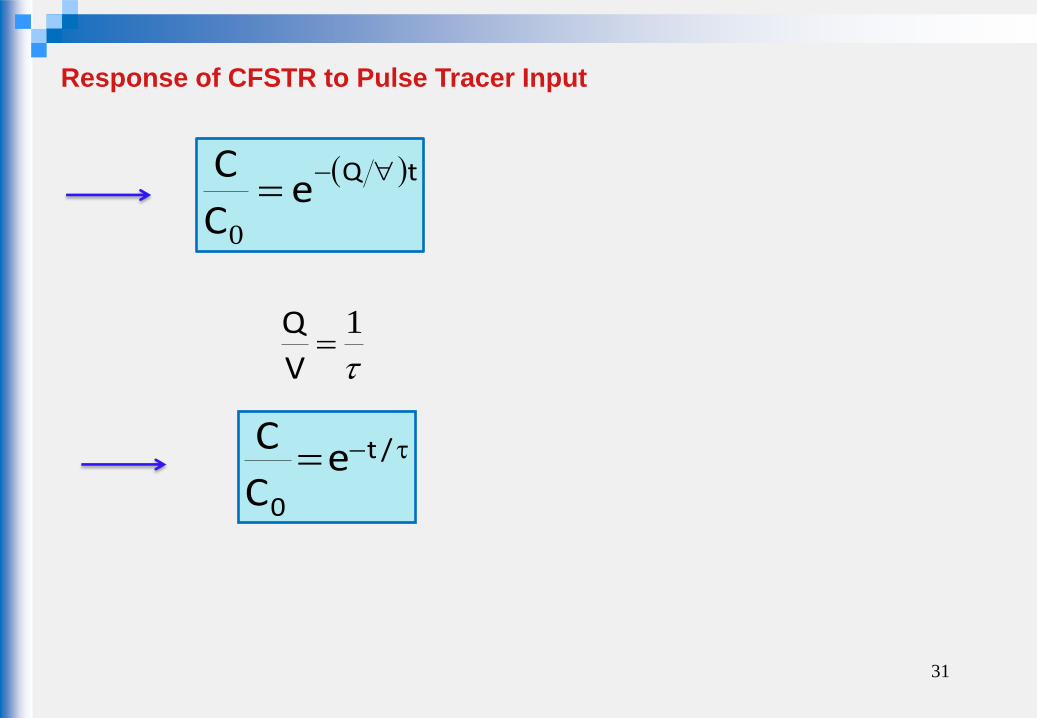
Response of CFSTR to Pulse Tracer Input
1
V
Q
32
This equation demonstrates that the effluent concentration from a CFSTR will be C = C0 at t =0, C =0 at infinite time, and decay exponentially between those extremes.
tQe
C
C
0
/t
0
eC
C
Source: MWH’s Principles of Water Treatment , Third Edition, Ch4 Kerry J. Howe, David W. Hand, John C. Crittenden, R. Rhodes Trussel and George Tchobanoglous, 2012 John Wiley & Sons, Inc.
∀-(∀ rQC)QCdt
dCi
QC)QCdt
dCi
-(∀
Divide by Q
CCdt
dC
Qi-
∀
since the tracer is non-reactive
Response of CFSTR to StepTracer Input
Ci is the influent tracer concentration.
34
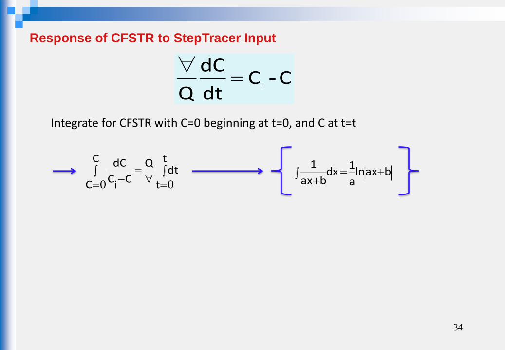
Integrate for CFSTR with C=0 beginning at t=0, and C at t=t
t
t
dtQC
C CiC
dC
00baxln
a
1dx
bax
1
CCdt
dC
Qi-
∀
Response of CFSTR to StepTracer Input

tQ
CCLn CCi
0
1
1
tQ
LnCCCLnii
tQ
CLnCCLn ii
0
tQ
LnCCCLnii
t.Q
Ci
CCLn i
tQ
iieCCC
∀--
tQ
i
eC
C 1
(Divide both sides by Ci)
35
tQ-
i
eC
C- ∀1
/t
i
eC
C 1

36
http://ceae.colorado.edu/~silverst/cven5534/IDEAL%20REACTORS.pdf
Response of CFSTR to StepTracer Input
R3
3
t
1
sec
1
m
sec/mQ
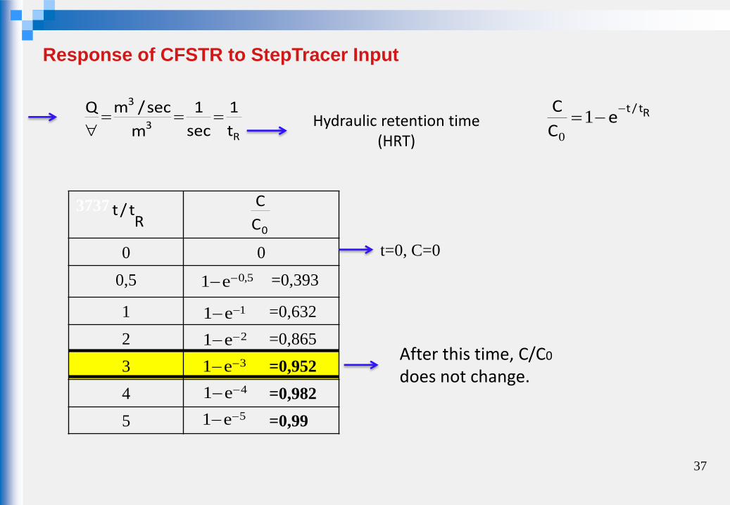
Hydraulic retention time
(HRT)
3737
0 0
0,5 =0,393
1 =0,632
2 =0,865
3 =0,952
4 =0,982
5 =0,99
Rt/t
0C
C
5,0e1
1e1
2e1
3e1
4e1
5e1
t=0, C=0
After this time, C/C0
does not change.
37
Rt/te
C
C 1
0
Response of CFSTR to StepTracer Input

After this time, C/C0
does not change
0
0,2
0,4
0,6
0,8
1
1,2
0 1 2 3 4 5 6
C/Co
t/tR
Response of CFSTR to StepTracer Input

39 http://ceae.colorado.edu/~silverst/cven5534/IDEAL%20REACTORS.pdf
Rt/te
C
C 1
0

40 http://ceae.colorado.edu/~silverst/cven5534/IDEAL%20REACTORS.pdf

41
Response of CFSTR to Non-Conservative (Reactant) Input
Unsteady State
Unsteady State Analysis
Reactors of concern in water treatment engineering typically operate at steady-state conditions.
∀-(∀ rQC)QCdt
dCo
Accumulation = Inflow - Outflow + Generation/Elimination
At steady state the accumulation term is zero. Therefore, there is no change in concentration within the reactor with time.

42
Response of CFSTR to Non-Conservative (Reactant) Input
Unsteady State
Unsteady State Analysis
However, sometimes the reactors operate at unsteady-state conditions
₋ When a reactor is first brought online,
₋ After maintanance or inoperation,
₋ When the inlet concentration, Co, changes.
Unsteady state: concentrations vary with time & accumulation is non-zero
The goal of unsteady state analysis is to determine the time necessary to reach steady-state operation.
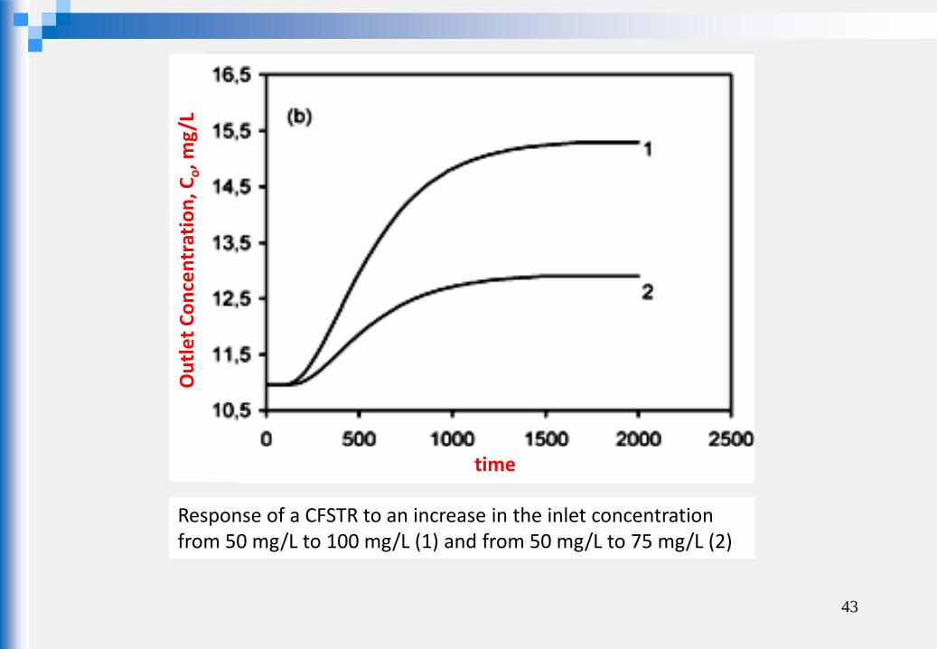
43
Ou
tle
t C
on
cen
trat
ion
, Co, m
g/L
time
Response of a CFSTR to an increase in the inlet concentration from 50 mg/L to 100 mg/L (1) and from 50 mg/L to 75 mg/L (2)

A reaction A B , known to be first order, is to be carried out in a CFSTR.
Water is run through the reactor at a flow rate Q (m3/sec ) and at t=0 the reactant A is added to the input stream on a continuous basis.
Determine the output concentration of A as a function of time and plot reactor-output response curves for reactant A.
44
Response of CFSTR to Non-Conservative (Reactant) Input
Unsteady State
oC,Q
,C
C,Q

inationlimeQCQCdt
dC0
.C.kQCQCdt
dC0 (Divide both sides by )
First-order rxn r=-kC elimination term =r = -kC ∴
45
Response of CFSTR to Non-Conservative (Reactant) Input
Unsteady State
oC,Q
,C
C,Q
Materials balance for the system:
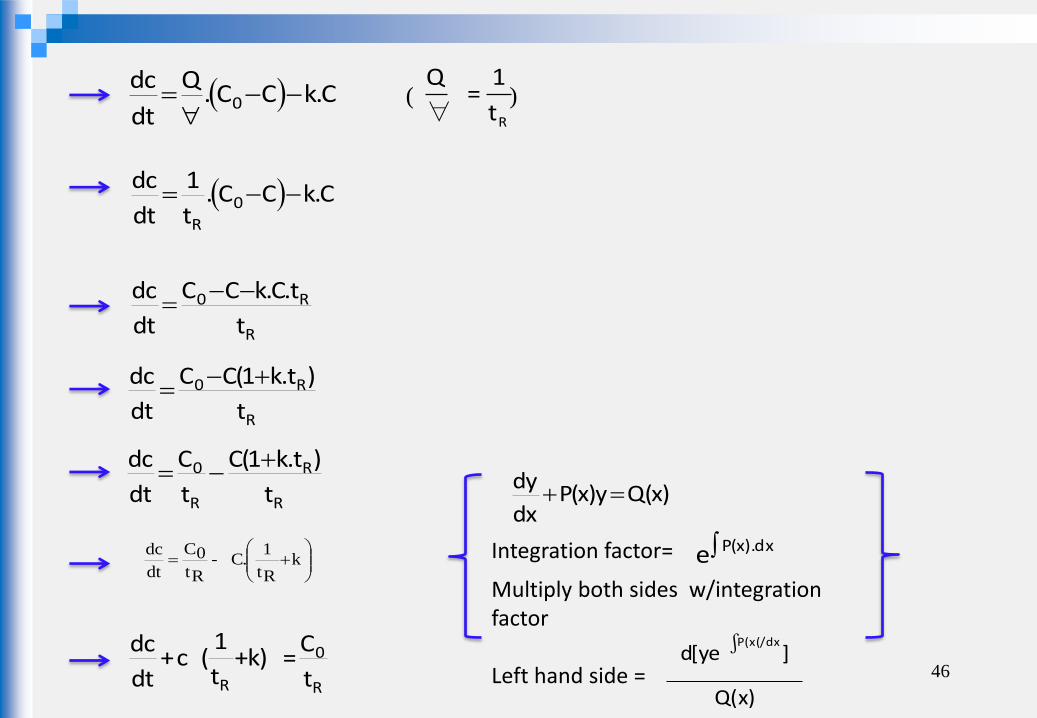
The unsteady-state analysis begins with a mass balance equation, which is written for a first-order reaction assuming constant volume and using detention time, τ = V /Q, as follows:
C.kCC.Q
dt
dc0
C.kCC.t
1
dt
dc0
R
R
R0
t
t.C.kCC
dt
dc
R
R0
t
)t.k1(CC
dt
dc
R
R
R
0
t
)t.k1(C
t
C
dt
dc
k
Rt
1.C-
Rt
0C
dt
dc
)x(Qy)x(Pdx
dy
Integration factor= dx).x(Pe
Multiply both sides w/integration factor Left hand side = 46
Rt
1=
Q
∀
Q(x)
]ye[d(/dxx(P ∫
( )
R
0
R t
C=)k+
t
1(c+
dt
dc

kt
1
R
t.dt. ee
Multiply both sides with integration factor.
t.o
R
tt. e.C.t
1.C.e
dt
dc.e
t.o
R
t
e.C.t
1
dt
e.Cd
dt.e.C.t
0tt
1C
C
e.Cd t0
R
t
0
t
axe
a
1dxaxe
t
0t
te.1
.0C.Rt
1tC
0C
t.e.C
47
R
0
R t
C=)k+
t
1(c+
dt
dc

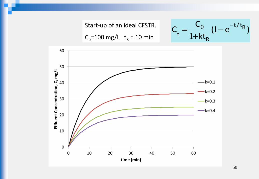
)e(kt
CC Rt/t
Rt
1
10
48
CFSTR, UNSTEADY-STATE FOR NON-CONSERVATIVE REACTANT HAVING 1ST ORDER REACTION RATE

49
0,00
0,10
0,20
0,30
0,40
0,50
0,60
0 10 20 30 40 50 60
C/C
o
time (min)
k=0.1
k=0.2
k=0.3
k=0.4
Start-up of an ideal CFSTR.
Co=100 mg/L tR = 10 min )e(
kt
CC Rt/t
Rt
1
10
50
Start-up of an ideal CFSTR.
Co=100 mg/L tR = 10 min )e(
kt
CC Rt/t
Rt
1
10
0
10
20
30
40
50
60
0 10 20 30 40 50 60
Effl
ue
nt
Co
nce
ntr
atio
n, C
, mg/
L
time (min)
k=0.1
k=0.2
k=0.3
k=0.4
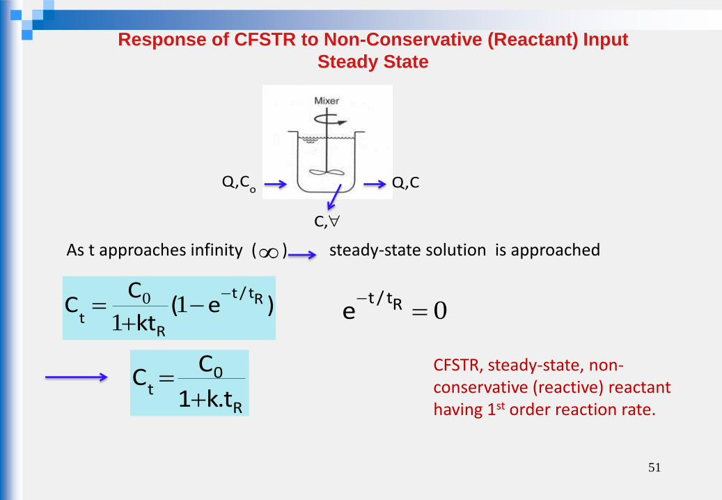
As t approaches infinity ( ) steady-state solution is approached
R
0t t.k1
CC
CFSTR, steady-state, non-conservative (reactive) reactant having 1st order reaction rate.
51
oC,Q
,C
C,Q
0 Rt/t
e
Response of CFSTR to Non-Conservative (Reactant) Input
Steady State
)e(kt
CC Rt/t
Rt
1
10
At steady-state 0dt
dc
( )CCt
1=kC 0
R
-
( )CC=kCt 0R-
0RC=C+kCt
R
0
t.k1
CC
52
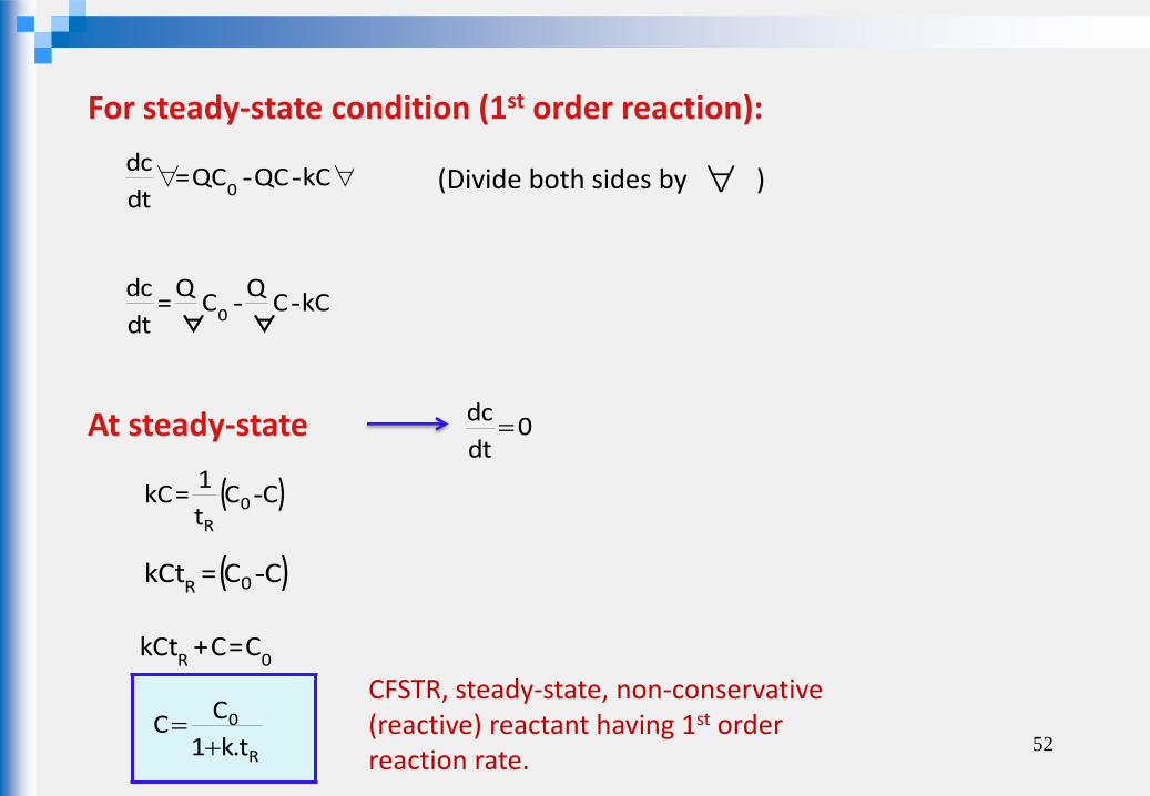
For steady-state condition (1st order reaction):
∀--∀ kCQCQC=dt
dc0
kCC ∀
QC ∀
Q=
dt
dc0
--
(Divide both sides by )
CFSTR, steady-state, non-conservative (reactive) reactant having 1st order reaction rate.
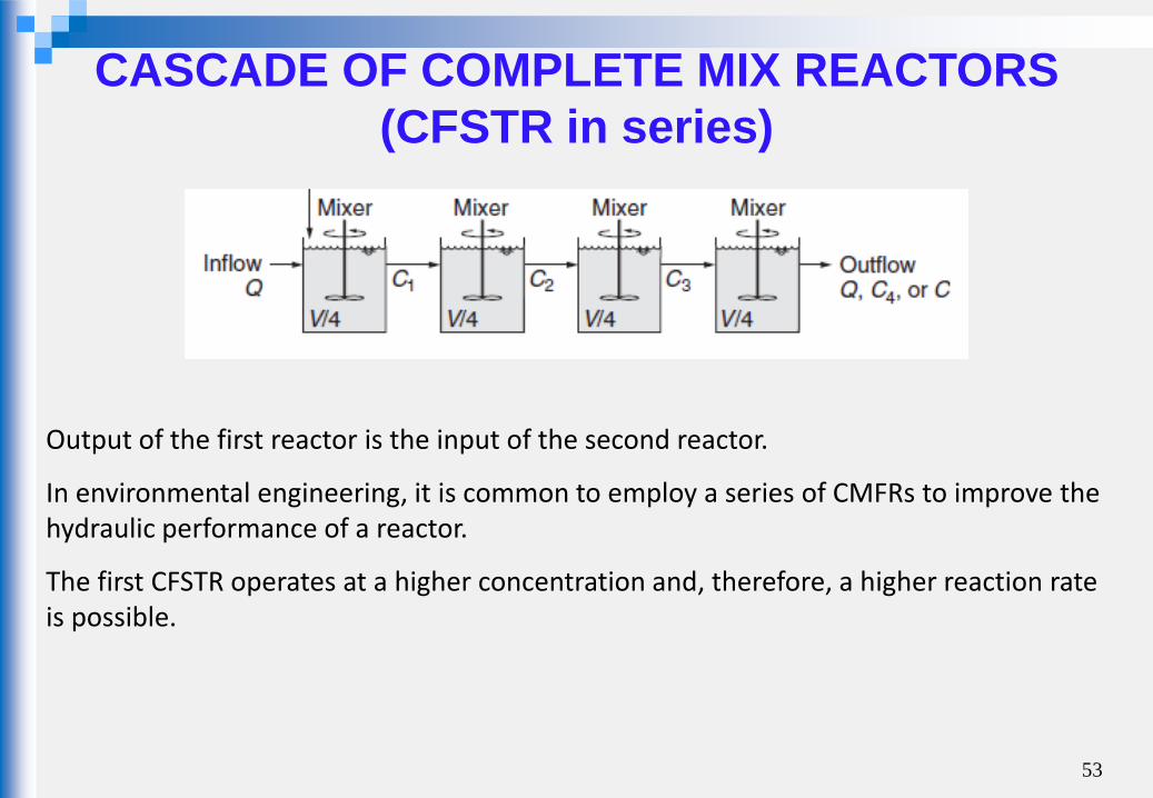
CASCADE OF COMPLETE MIX REACTORS
(CFSTR in series)
53
Output of the first reactor is the input of the second reactor.
In environmental engineering, it is common to employ a series of CMFRs to improve the hydraulic performance of a reactor.
The first CFSTR operates at a higher concentration and, therefore, a higher reaction rate is possible.

CASCADE OF COMPLETE MIX REACTORS
(CFSTR in series)
At steady-state: 1st reactor
1101r+QCQC=
dt
dc∀-∀
r+CQ
CQ
=dt
dc1
10
1 ∀-
∀
r+Ct
1C
t
1=0
11R
01R
-1 2 n
. . . .
For 1st order reaction: 11
10
1
1-
10 kCC
tC
t RR
)k+t
1(CC
t
1=0
1R10
1R
-
t
kt+1CC
t
1=0
1R
1R10
1R
-1R
01 kt1
CC
54

2nd reactor 2212
r+QCQC=dt
dc∀-∀
r+CQ
CQ
=dt
dc2
21
2 ∀-
∀
r+Ct
1C
t
1=0
22R
12R
-
For 1st order reaction: 22
21
2
1-
10 kCC
tC
t RR
)k+t
1(CC
t
1=0
2R21
2R
-
t
kt+1CC
t
1=0
2R
2R21
2R
-
55
1 2 n
. . . .
2R
12 kt1
CC
1R
01 kt+1
C=C
2R1R
02 kt1.kt1
CC
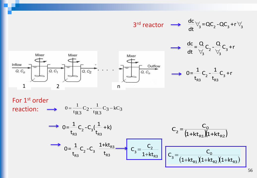
3rd reactor 3323r+QCQC=
dt
dc∀-∀
r+CQ
CQ
=dt
dc3
32
3 ∀-
∀
r+Ct
1C
t
1=0
33R
23R
-
For 1st order reaction: 3kC3C
3Rt
1-2C
3Rt
10
)k+t
1(CC
t
1=0
3R32
3R
-
t
kt+1CC
t
1=0
3R
3R32
3R
-
56
1 2 n
. . . .
3R
23 kt1
CC
( )( )2R1R
02 kt+1kt+1
C=C
3R2R1R
03 kt1kt1kt1
CC
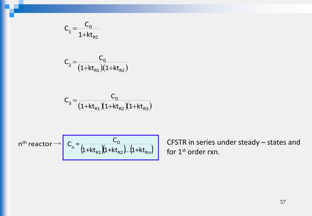
( )( ) ( )Rn2R1R
0n
th
kt+1...kt+1kt+1
C=C reactor n →
57
CFSTR in series under steady – states and for 1st order rxn.
1R
01 kt1
CC
2R1R
02 kt1.kt1
CC
3R2R1R
03 kt1kt1kt1
CC

is used to model the flow regime that exists between the hydraulic flow patterns
corresponding to the complete and plug flow reactors.
If the series is composed of one reactor complete mix regime prevails If the series consists of an infinite number plug-low regime prevails of reactors in series
Application: In modeling rivers within small increments (segments) 58
CASCADE of COMPLETE MIX REACTORS (Complete Mix Reactor in Series)
n-1 n n+1

EXAMPLE 1: The river reach shown has been divided into 5 segments based on measured velocities and depths. An industrial facility is planned just upstream of the 1st segment and it is necessary to estimate effect of ww discharge. A series of dye experiments have been run and each of the segments was found to behave as an approximate CFSTR. The pollutant is expected to disappear according to 1st order reaction. For the data given determine the steady-state pollutant conentration in each segment.
30
1
3river
m/g30C
day2,0k
sec/m5Q
59
Ref: Tchobanoglous and Scroeder, 1985, Addison-Wesley Publishing Company
V1=8.68 x 10 ^5 m3
V2=25.9x 10 ^5 m3
V3=17.28 x 10 ^5 m3
v4=8.64 x 10 ^5 m3
V5=25.92x 10 ^5 m3
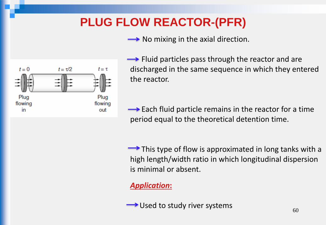
No mixing in the axial direction. Fluid particles pass through the reactor and are discharged in the same sequence in which they entered the reactor. Each fluid particle remains in the reactor for a time period equal to the theoretical detention time. This type of flow is approximated in long tanks with a high length/width ratio in which longitudinal dispersion is minimal or absent.
Application: Used to study river systems
60
PLUG FLOW REACTOR-(PFR)

61 http://ceae.colorado.edu/~silverst/cven5534/IDEAL%20PLUG%20FLOW%20REACTOR.pdf
62
PLUG FLOW REACTOR-(PFR)
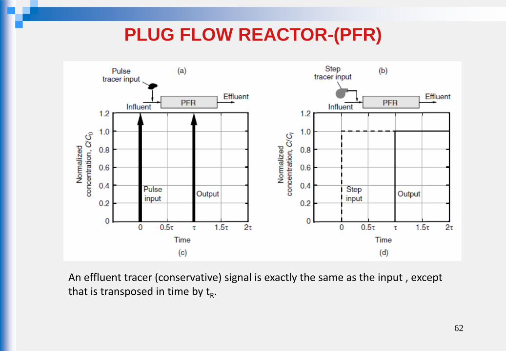
An effluent tracer (conservative) signal is exactly the same as the input , except that is transposed in time by tR.
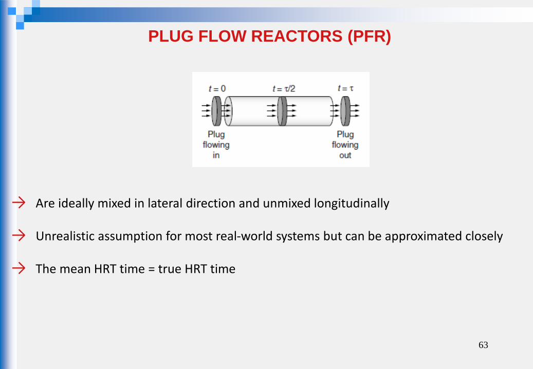
PLUG FLOW REACTORS (PFR)
→ Are ideally mixed in lateral direction and unmixed longitudinally
→ Unrealistic assumption for most real-world systems but can be approximated closely
→ The mean HRT time = true HRT time
63

→ PF conditions are achieved by designing long and narrow reactors or placing baffles in a reactor.
64
Ref: Tchobanoglous and Scroeder, 1985, Addison-Wesley Publishing Company
( ) r+CCxΔA
Q=
t
cxΔ+xx -
∂
∂
Materials Balance:
∀rxxQC-x0QC∀t∂
c∂
( ) r+CCΔ
Q=
t
cxΔ+xx -
∀∂
∂
(Divide both sides to )
65
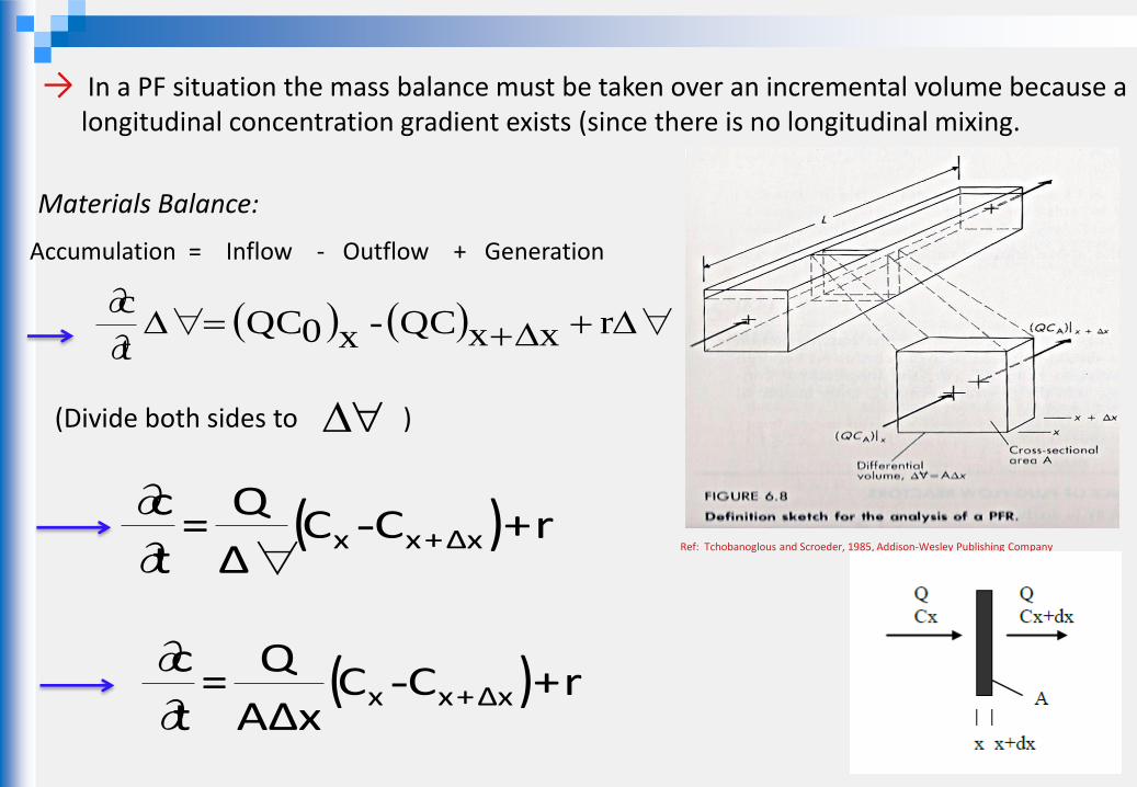
→ In a PF situation the mass balance must be taken over an incremental volume because a
longitudinal concentration gradient exists (since there is no longitudinal mixing.
Accumulation = Inflow - Outflow + Generation
Ref: Tchobanoglous and Scroeder, 1985, Addison-Wesley Publishing Company
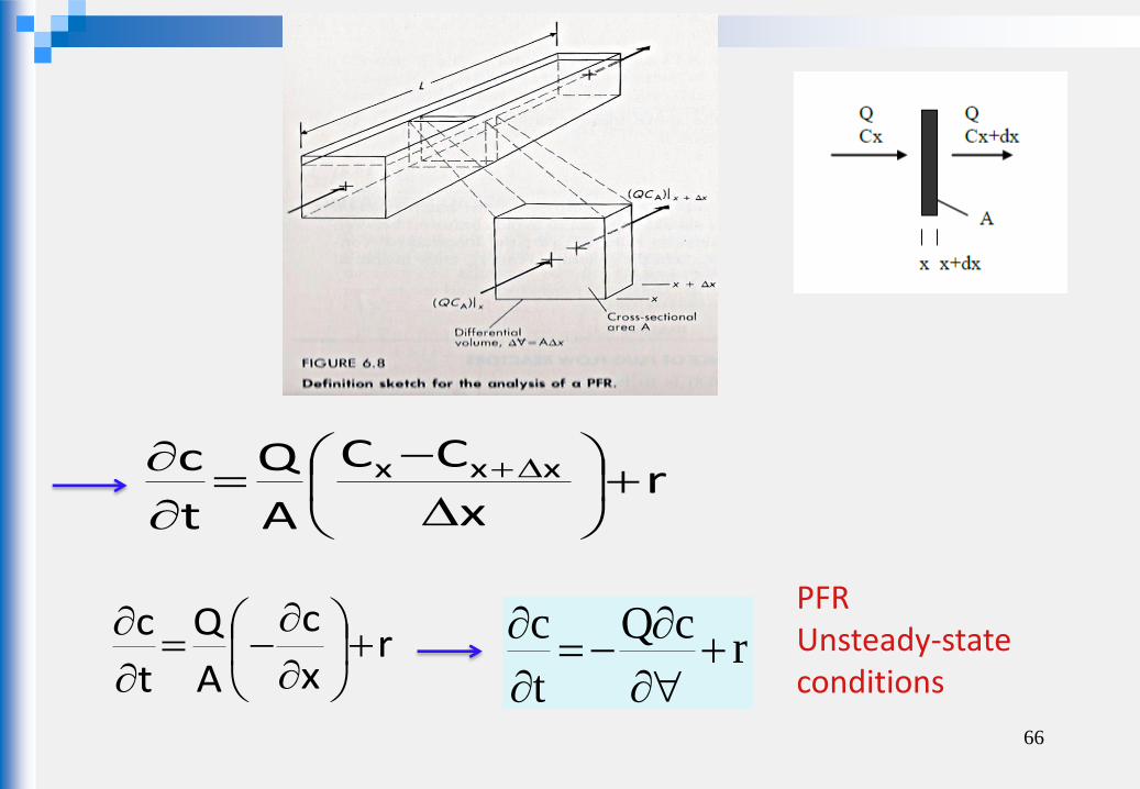
66
rx
c
A
Q
t
c
r
cQ
t
c
PFR Unsteady-state conditions
rx
CC
A
Q
t
c xxx
@ steady-state conditions
0t
c
Rt
ccQr
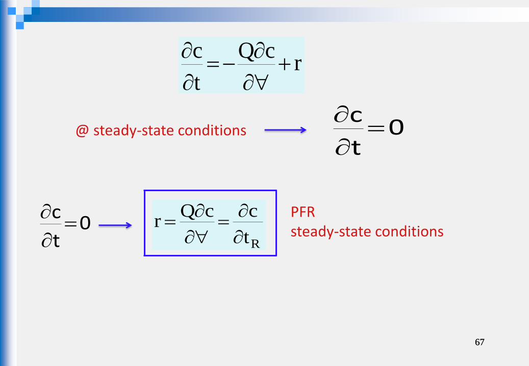
67
0t
c
rcQ
t
c
PFR steady-state conditions
67

EXAMPLE 2: A plug flow reactor (PFR) is to be used to carry out the reaction
A B The reaction is first order and the rate is characterized as ra=-kCA
Determine the steady-state effluent concentration as a function of tR .
68

69
http://ceae.colorado.edu/~silverst/cven5534/IDEAL%20PLUG%20FLOW%20REACTOR.pdf
Solution for Example 2 (Derivation of Effluent Cocnentration Equation)

70
http://ceae.colorado.edu/~silverst/cven5534/IDEAL%20PLUG%20FLOW%20REACTOR.pdf

71
EXAMPLE 4: Determine the volumes of two identical CFSTR reactors in series to provide the same degree of treatment for the conditions given in Example 1.
EXAMPLE 5: Determine the volume of a PFR to provide the same degree of treatment for the conditions given Example 1.
EXAMPLE 3: Determine the volume of a CFSTR required to give a treatment efficiency of 95% for a substance that decay according to half – order kinetics with a rate constant of 0.05 (mg/L)1/2 . The flow rate is steady at 300L/hr and the influent concentration is 150mg/L.
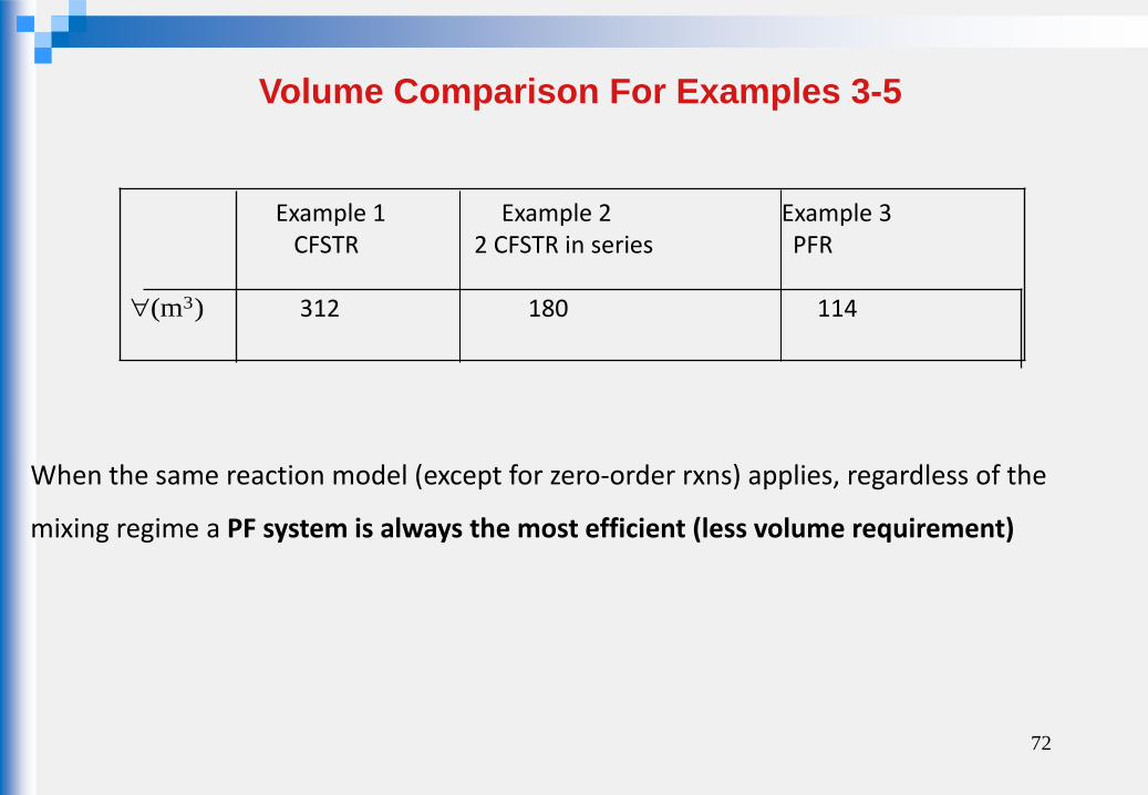
Volume Comparison For Examples 3-5
)m( 3
Example 1 Example 2 Example 3 CFSTR 2 CFSTR in series PFR 312 180 114
When the same reaction model (except for zero-order rxns) applies, regardless of the
mixing regime a PF system is always the most efficient (less volume requirement)
72
73
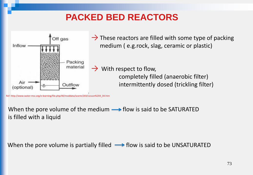
PACKED BED REACTORS
→ These reactors are filled with some type of packing medium ( e.g.rock, slag, ceramic or plastic)
→ With respect to flow, completely filled (anaerobic filter) intermittently dosed (trickling filter)
When the pore volume of the medium flow is said to be SATURATED is filled with a liquid
When the pore volume is partially filled flow is said to be UNSATURATED
Ref: http://www.water-msc.org/e-learning/file.php/40/moddata/scorm/203/Lesson%204_04.htm
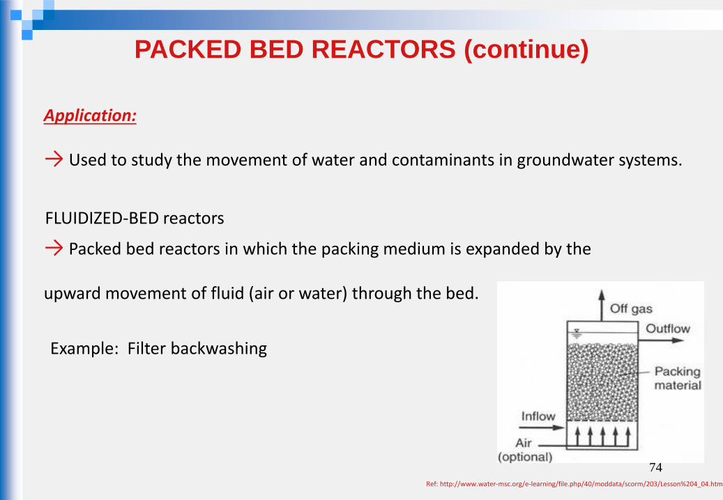
Application:
→ Used to study the movement of water and contaminants in groundwater systems.
→ Packed bed reactors in which the packing medium is expanded by the
upward movement of fluid (air or water) through the bed.
FLUIDIZED-BED reactors
Example: Filter backwashing
74
PACKED BED REACTORS (continue)
Ref: http://www.water-msc.org/e-learning/file.php/40/moddata/scorm/203/Lesson%204_04.htm