reactive power management products - shrimanshrimanelectrical.com/lnt/rpm catalogue.pdf ·...
TRANSCRIPT
Reactive Power ManagementProducts
About us
Larsen & Toubro is a technology-driven USD 8.5 billion company that infuses engineering with imagination. The Company offers a wide range of advanced solutions in the field of Engineering, Construction, Electrical & Automation, Machinery and Information Technology.
L&T Switchgear, which forms part of the Electrical & Automation business, is India's largest manufacturer of low voltage switchgear, with the scale, sophistication and range to meet global benchmarks. With over four decades of experience in this field, the Company today enjoys a leadership position in the Indian market with growing presence in international markets.
It offers a complete range of products including controlgear, powergear, motor starters, energy meters, wires and host of other accessories. Most of our product lines conform to international standards, carry CE marking and are certified.
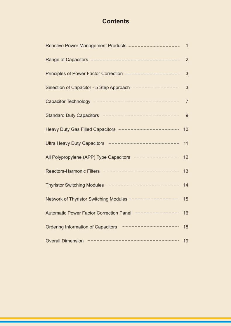
Contents
Reactive Power Management Products
Range of Capacitors
Principles of Power Factor Correction
Selection of Capacitor - 5 Step Approach
Capacitor Technology
Standard Duty Capacitors
Heavy Duty Gas Filled Capacitors
Ultra Heavy Duty Capacitors
Reactors-Harmonic Filters
Switching Modules
Network of Thyristor Switching Modules
Automatic Power Factor Correction Panel
Ordering Information of Capacitors
Overall Dimension
All Polypropylene (APP) Type Capacitors
Thyristor
1
2
3
3
7
9
10
11
12
13
14
15
16
18
19

Reactive Power Management Products
1
APFC PanelsReactors
Wires
MCCBs
MCBs
Power Capacitors
Thyristor Switching Modules
Indicating Devices
Quasar Meters
Capacitor Duty Contactors
2
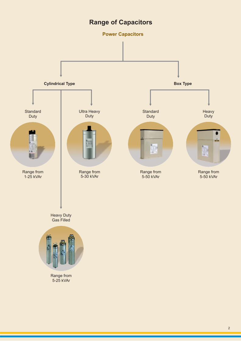
Range of Capacitors
Range from5-25 kVAr
Heavy Duty Gas Filled
Cylindrical Type
Range from1-25 kVAr
Standard Duty
Ultra HeavyDuty
Range from5-30 kVAr
Standard Duty
Range from5-50 kVAr
Range from5-50 kVAr
Box Type
HeavyDuty
Power Capacitors

Principles of Power Factor Correction
3
A vast majority of electrical loads in low voltage industrial installations are inductive in nature. Typical examples are motors, transformers, drives & fluorescent lighting. Such loads consume both active and reactive power. The active power is used by the load to meet its real output requirements whereas reactive power is used by the load to meet its
0 magnetic field requirements. The reactive power (inductive) is always 90 lagging with respect to active power as shown in figure1. Figure 2 & 3 show the flow of kW, kVAr and kVA in a network.
Power Factor Correction Capacitors have been used for many years as the most cost effective solution for PF improvement. Modern electrical networks are continuously evolving into more complex installations due to the increasing usage of non-linear loads, sophisticated control & automation, UPS systems, energy efficiency improvement devices etc.This evolution is also accompanied by increased dependency on captive power generation as well as growing concerns about incoming supply power quality.In this background, it is necessary to involve the Power Factor Correction solution to a higher level so as to ensure sustainable achievement of high PF & acceptable harmonic distortion levels.
also
The selection of the correct type of PFC Capacitors & Filter reactors thus needs better understanding of the various issues involved.
This publication outlines a “5 Step” technology based approach, simplified for easier understanding to enable the correct selection of PFC Capacitors & Filter Reactors.
Selection of Capacitor - 5 Step Approach
Flow of active and reactive power always takes place in electrical installations. This means that the supply system has to be capable of supplying both active and reactive power. The supply of reactive power from the system results in reduced installation efficiency due to:
Increased current flow for a given loadHigher voltage drops in the systemIncrease in losses of transformers, switchgear and cablesHigher kVA demand from supply system as given in figure 2Higher electricity cost due to levy of penalties/loss of incentives
It is therefore necessary to reduce & manage the flow of reactive power to achieve higher efficiency of the electrical system and reduction in cost of electricity consumed. The most cost effective method of reducing and managing reactive power is by power factor improvement through Power Capacitors. The concept of reduction in kVA demand from the system is shown in figure 3.
l
l
l
l
l
Figure 1: Phase relationship between Active and Reactive power
Figure 2: Network without Capacitor
Figure 3: Network with Capacitor
Supply Bus Supply Bus
Reactive Power
Active power
kVA
kW kVAr
LOAD LOAD
kVA
kW
kVAr
Capacitor

4
Step 1: Calculation of kVAr required for Industries & Distribution Networks
In electrical installations, the operating load kW and its average power factor (PF) can be ascertained from the electricity bill. Alternatively, it can also be easily evaluated by the formula: Average PF = kW/kVA
Operating load kW = kVA Demand x Average PF
The Average PF is considered as the initial PF and the final PF can be suitably assumed as target PF. In such cases required capacitor kVAr can be calculated as sited in below table.
Example to calculate the required kVAr compensation for a 500 kW installation to improve the PF from 0.75 to 0.96
kVAr = kW x multiplying factor from table = 500 x 0.590 = 295 kVAr
Note: Table is based on the following formula: kVAr required = kW (tanØ - tanØ ) 1 2-1 -1 where Ø = cos (PF ) and Ø = cos (PF ).1 1 2 2
0.99
2.149
2.018
1.898
1.788
1.685
1.590
1.500
1.416
1.337
1.262
1.191
1.123
1.058
0.996
0.936
0.878
0.821
0.766
0.739
0.713
0.660
0.608
0.556
0.503
0.477
0.451
0.424
0.397
0.370
0.342
0.313
0.284
0.253
0.220
0.186
0.97
2.041
1.910
1.790
1.680
1.577
1.481
1.392
1.308
1.229
1.154
1.083
1.015
0.950
0.888
0.828
0.770
0.713
0.658
0.631
0.605
0.552
0.499
0.447
0.395
0.369
0.343
0.316
0.289
0.262
0.234
0.253
0.175
0.145
0.112
0.078
0.98
2.088
1.958
1.838
1.727
1.625
1.529
1.440
1.356
1.276
1.201
1.130
1.062
0.998
0.935
0.875
0.817
0.761
0.706
0.679
0.652
0.699
0.547
0.495
0.443
0.417
0.390
0.364
0.337
0.309
0.281
0.313
0.223
0.192
0.160
0.126
0.96
2.000
1.869
1.749
1.639
1.536
1.440
1.351
1.267
1.188
1.113
1.042
0.974
0.909
0.847
0.787
0.729
0.672
0.617
0.590
0.563
0.511
0.458
0.406
0.354
0.328
0.302
0.275
0.248
0.221
0.193
0.205
0.134
0.104
0.071
0.037
0.9
1.807
1.676
1.557
1.446
1.343
1.248
1.158
1.074
0.995
0.920
0.849
0.781
0.716
0.654
0.594
0.536
0.480
0.425
0.38
0.371
0.318
0.266
0.214
0.162
0.135
0.109
0.082
0.055
0.028
0.91
1.836
1.705
1.585
1.475
1.372
1.276
1.187
1.103
1.024
0.949
0.878
0.810
0.745
0.683
0.623
0.565
0.508
0.453
0.426
0.400
0.347
0.294
0.242
0.190
0.164
0.138
0.111
0.084
0.057
0.029
0.030
0.92
1.865
1.735
1.615
1.504
1.402
1.306
1.217
1.133
1.053
0.979
0.907
0.839
0.775
0.712
0.652
0.594
0.538
0.483
0.456
0.429
0.376
0.324
0.272
0.220
0.194
0.167
0.141
0.114
0.086
0.058
0.060
0.94
1.928
1.798
1.678
1.567
1.465
1.369
1.280
1.196
1.116
1.042
0.970
0.903
0.838
0.775
0.715
0.657
0.061
0.546
0.519
0.492
0.439
0.387
0.335
0.283
0.257
0.230
0.204
0.177
0.149
0.121
0.127
0.063
0.032
0.95
1.963
1.832
1.712
1.602
1.499
1.403
1.314
1.230
1.151
1.076
1.005
0.937
0.872
0.810
0.750
0.692
0.635
0.580
0.553
0.526
0.474
0.421
0.369
0.317
0.291
0.265
0.238
0.211
0.184
0.156
0.164
0.097
0.067
0.034
0.93
1.896
1.766
1.646
1.535
1.432
1.337
1.247
1.163
1.084
1.009
0.938
0.870
0.805
0.743
0.683
0.625
0.569
0.514
0.487
0.460
0.407
0.355
0.303
0.251
0.225
0.198
0.172
0.145
0.117
0.089
0.093
0.031
Initial PF
0.4
0.42
0.44
0.46
0.48
0.5
0.52
0.54
0.56
0.58
0.6
0.62
0.64
0.66
0.68
0.7
0.72
0.74
0.75
0.76
0.78
0.8
0.82
0.84
0.85
0.86
0.87
0.88
0.89
0.9
0.91
0.92
0.93
0.94
0.95
Target PF
5
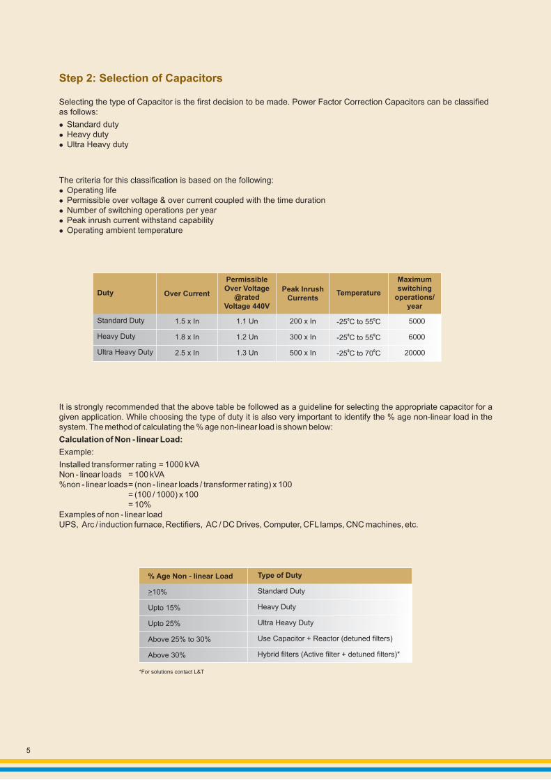
It is strongly recommended that the above table be followed as a guideline for selecting the appropriate capacitor for a given application. While choosing the type of duty it is also very important to identify the % age non-linear load in the system. The method of calculating the % age non-linear load is shown below:
Calculation of Non - linear Load:
Example:
Installed transformer rating = 1000 kVANon - linear loads = 100 kVA%non - linear loads= (non - linear loads / transformer rating) x 100
= (100 / 1000) x 100= 10%
Examples of non - linear loadUPS, Arc / induction furnace, Rectifiers, AC / DC Drives, Computer, CFL lamps, CNC machines, etc.
Selecting the type of Capacitor is the first decision to be made. Power Factor Correction Capacitors can be classified as follows:
lStandard dutylHeavy dutylUltra Heavy duty
The criteria for this classification is based on the following:lOperating lifelPermissible over voltage & over current coupled with the time durationlNumber of switching operations per yearlPeak inrush current withstand capabilitylOperating ambient temperature
Standard Duty
Heavy Duty
Ultra Heavy Duty
1.5 x In
1.8 x In
2.5 x In
1.1 Un
1.2 Un
1.3 Un
200 x In
300 x In
500 x In
0 0-25 C to 55 C
0 0-25 C to 55 C
0 0-25 C to 70 C
5000
6000
20000
Duty Over Current
PermissibleOver Voltage
@ratedVoltage 440V
Peak InrushCurrents
Temperature
Maximumswitching
operations/ year
*For solutions contact L&T
% Age Non - linear Load
>10%
Upto 15%
Upto 25%
Above 25% to 30%
Above 30%
Type of Duty
Standard Duty
Heavy Duty
Ultra Heavy Duty
Use Capacitor + Reactor (detuned filters)
Hybrid filters (Active filter + detuned filters)*
Step 2: Selection of Capacitors
6
Capacitors are manufactured in three different types such as Standard duty, Heavy duty and Ultra Heavy duty. The Standard duty capacitors are manufactured using standard thickness of dielectric material with heavy edge metallization.Heavy duty capacitors are manufactured using thicker material and in lower width which increases current handling capacity as well as reduces temperature rise. Ultra Heavy duty capacitors are manufactured using thicker material, in lower width and have greater ability to handle in-rush current.
To estimate whether fixed compensation or automatic compensation is to be used. In order to achieve high power factor i.e., close to unity PF, the following guideline may be adopted to make a decision.If the total kVAr required by the installation is less than 15% of the rating of the incoming supply transformers, then the use of fixed capacitors may be adopted at various points in the installation. If the kVAr required by the installation is more than 15% of the rating of the incoming supply transformers, then automatic power factor correction solution needs to be adopted.APFC panels with suitable kVAr outputs may be distributed and connected across various points within the installation.
Note: As in the case of selection of capacitors De-tuned filter APFC panels must be selected if non-linear loads exceed as per previous table.
To make a choice between the use of Capacitors or Capacitors + Filter reactors. This is important, because it is necessary to avoid the risk of “Resonance” as the phenomena of “Resonance” can lead to current and harmonic amplification which can cause wide spread damage to all Electrical & Electronic equipment in the installation including Capacitors. This can be avoided by installing capacitor + filter reactor.
Caution: It is safer to select a combination of “Capacitor + Filter reactor” so as to ensure that PF improvement is achieved in a reliable manner and the risk of resonance is avoided.
To decide whether transient free PF correction is required. This is due to the fact that conventional switching techniques of capacitors involving electro-mechanical contactors will give rise to transient phenomena. This transient phenomena can interact with impedances present in the installation to create “Surges”. This occurrence of surges can cause serious damage to sensitive electronics and automation resulting in either their malfunction or permanent damage. The transient phenomenon is a sudden rise in voltage or current at the point of switching.In this background, it is important to ensure that all the capacitors installed are switched in a transient free manner so as to ensure reliable performance of the installation. In such a situation, it is necessary to specify the use of Thyristor switches for transient free switching of Capacitors.
Note: Thyristor switching can also be used for dynamic compensation which is needed if the fluctuation of loads is very high; such as lifts, welding load is very high; fast presses etc.
Step 3: To Avoid Risk of Resonance
Capacitor Technology & Construction Details
Step 4: To Achieve Target PF
Step 5: To Achieve Transient Free Unity PF

Capacitor Technology
7
For a self-healing dielectric, impregnation is basically not required. However, our LT-type capacitors are impregnated to eliminate environmental influences and to guarantee reliable, long-term operation. Vacuum impregnation eliminates air and moisture, improves “self-healing” and reduces thermal resistance.
Capacitors are used in many diverse applications, and many different capacitor technologies are available. In low voltage applications, LT cylindrical capacitors which are made in accordance with metallized polypropylene technology have proved to be most appropriate and also the most cost effective. Dependent on the nominal voltage of the capacitor, the thickness of the polypropylene film will differ.
At the end of service life, or due to inadmissible electrical or thermal overload, an insulation breakdown may occur. A breakdown causes a small arc which evaporates the metal layer around the point of breakdown and re-establishes the insulation at the place of perforation. After electric breakdown, the capacitor can still be used. The decrease of Capacitance caused by a self-healing process is less than 100 pF. The self-healing process lasts for a few microseconds only and the energy necessary for healing can be measured only by means of sensitive instruments.
Electrodes (metallized)
1
Polypropylene Film
Electric Contact (schooping)
Non-metallized Edge
3 4 2 4 3
Design of LT Capacitor
Self - Healing Breakdown
Non-conductive Insulating Area
Electrodes (metallized)
Point of Breakdown
43
Top View
Polypropylene Film 2 1
Self - Healing
Self - Healing Breakdown

8
At the end of service life, due to inadmissible electrical or thermal overload, an overpressure builds up and causes an expansion of the cover. Expansion over a certain limit causes the tear-off of the internal fuses. The active capacitor elements are thus cut-off from the source of supply. The pressure within the casing separates the breaking point so rapidly that no harmful arc can occur.
Technologically similar to cylindrical capacitors, box type capacitors consist of a number of three phase cylindrical capacitor cells. The individual cells are wired together and mounted on a steel frame. The steel frame together with the cells is housed in a common sheet steel casing. The enclosure is powder coated and is designed to protect the capacitor cells from dust and moisture. Ease of mounting is ensured by 4 drillings at the bottom of the container.
This design ensures highest safety by:
Self healing technology
Over pressure tear - off fuse
Robust steel container
Massive connection studs
l
l
l
l
Box Type Capacitors
Operating Condition
Torn - off Condition
Over pressure Tear - off Fuse
9
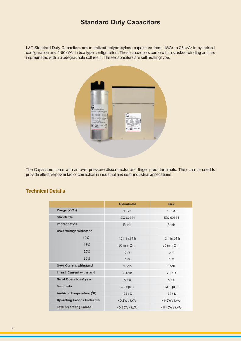
Standard Duty Capacitors
L&T Standard Duty Capacitors are metalized polypropylene capacitors from 1kVAr to 25kVAr in cylindrical configuration and 5-50kVAr in box type configuration. These capacitors come with a stacked winding and are impregnated with a biodegradable soft resin. These capacitors are self healing type.
The Capacitors come with an over pressure disconnector and finger proof terminals. They can be used to provide effective power factor correction in industrial and semi industrial applications.
Cylindrical
1 - 25
IEC 60831
Resin
12 h in 24 h
30 m in 24 h
5 m
1 m
1.5*In
200*In
5000
Clamptite
-25 / D
<0.2W / kVAr
<0.45W / kVAr
Box
5 - 100
IEC 60831
Resin
12 h in 24 h
30 m in 24 h
5 m
1 m
1.5*In
200*In
5000
Clamptite
-25 / D
<0.2W / kVAr
<0.45W / kVAr
Range (kVAr)
Standards
Impregnation
Over Voltage withstand
10%
15%
20%
30%
Over Current withstand
Inrush Current withstand
No of Operations/ year
Terminals
0Ambient Temperature ( C)
Operating Losses Dielectric
Total Operating losses
Technical Details

10
Heavy Duty Capacitors
L&T Heavy Duty Capacitors are available from 1-30kVAr in cylindrical and box type construction. These capacitors have an inrush current withstand of 300 In and an overload withstand capacity of 1.8 In. These capacitors have all features of standard capacitors however; these are dry type capacitors.
The Capacitors are subjected to an extended period of drying after which the casing is filled with an inert gas to prevent corrosion of the winding elements and inner electrical contacts. Compact design ensures space saving. Heavy Duty capacitors have a long life of 130000 hours.
Cylindrical
30
IEC 60831
Resin
12 h in 24 h
30 m in 24 h
5 m
1 m
1.8*In
250*In
8000
Faston / Screw
-25 / D
<0.2W / kVAr
<0.35W / kVAr
Cylindrical
30
IEC 60831
Inert Gas
12 h in 24 h
30 m in 24 h
5 m
1 m
1.8*In
250*In
8000
Faston / Screw
-40 / D
<0.2W / kVAr
<0.35W / kVAr
Box
5 - 50
IEC 60831
Resin
12 h in 24 h
30 m in 24 h
5 m
1 m
1.8*In
300*In
8000
Faston / Screw
-25 / D
<0.2W / kVAr
<0.35W / kVAr
Range (kVAr)
Standards
Impregnation
Over Voltage withstand
10%
15%
20%
30%
Over Current withstand
Inrush current withstand
No. of Operations / year
Terminals
0Ambient Temperature ( C)
Operating Losses Dielectric
Total Operating Losses
Gas Filled Capacitors
Technical Details

11
Ultra Heavy Duty Capacitors
The winding element of Ultra Heavy Duty Capacitors consists of a dielectric polypropylene film and an electrode of double sided metalized paper. The winding construction achieves low losses and high pulse current withstand capability. Oil is used for impregnation of the capacitor. Oil impregnation enables good heat dissipation from the winding element to the aluminum can's surface, thus preventing hot spots in the winding element. The capacitor is designed to operate under ambient temperatures upto 70 degrees.
Range (kVAr)
Standards
Impregnation
Over Voltage withstand
10%
15%
20%
30%
Over Current withstand
Inrush Current withstand
No. of Operations/ year
Life (hrs)
Terminals
Ambient Temperature
Operating Losses Dielectric
Operating Losses
0( C)
Total
Cylindrical
5 - 30
IEC 60831
Oil
12 h in 24 h
30 m in 24 h
5 m
1 m
3*In
500*In
20000
300000
Clamtite
-40 to 70
<0.2W / kVAr
<0.35W / kVAr
Technical Details
12
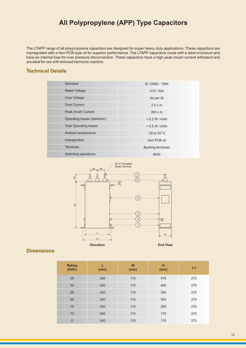
All Polypropylene (APP) Type Capacitors
The LTAPP range of all polypropylene capacitors are designed for super heavy duty applications. These capacitors are impregnated with a Non PCB type oil for superior performance. The LTAPP capacitors come with a steel enclosure and have an internal fuse for over pressure disconnection. These capacitors have a high peak inrush current withstand and are ideal for use with detuned harmonic reactors.
Rating (kVAr)
L (mm)
W (mm)
H (mm) L1
35
30
25
20
15
10
5
240
240
240
240
240
240
240
115
115
115
115
115
115
115
475
400
350
300
225
175
115
270
270
270
270
270
270
270
60 60
70
7
5
4
10
3
2
1
L
L1
Elevation End View
w
M-10 ThreadedBrass Terminal
Technical Details
Dimensions
Standard
Rated Voltage
Over Voltage
Over Current
Peak inrush Current
Operating losses (dielectric)
Total Operating losses
Ambient temperature
Impregnation
Terminals
Switching operations
IS 13585 - 1994
415 / 440
As per IS
2.0 x In
350 x In
< 0.2 W / kVAr
< 0.5 W / kVAr
0-25 to 55 C
Non PCB oil
Bushing terminals
8000
13
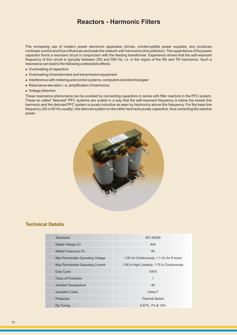
Reactors - Harmonic Filters
The increasing use of modern power electronic apparatus (drives, uninterruptible power supplies, etc) produces nonlinear current and thus influences and loads the network with harmonics (line pollution). The capacitance of the power capacitor forms a resonant circuit in conjunction with the feeding transformer. Experience shows that the self-resonant frequency of this circuit is typically between 250 and 500 Hz, i.e. in the region of the 5th and 7th harmonics. Such a resonance can lead to the following undesirable effects:
Overloading of capacitors
Overloading of transformers and transmission equipment
Interference with metering and control systems, computers and electrical gear
Resonance elevation, i.e. amplification of harmonics
Voltage distortion
These resonance phenomena can be avoided by connecting capacitors in series with filter reactors in the PFC system. These so called “detuned” PFC systems are scaled in a way that the self-resonant frequency is below the lowest line harmonic and the detuned PFC system is purely inductive as seen by harmonics above this frequency. For the base line frequency (50 or 60 Hz usually), the detuned system on the other hand acts purely capacitive, thus correcting the reactive power.
l
l
l
l
l
Technical Details
Standards
Rated Voltage (V)
Rated Frequency (F)
Max Permissible Operating Voltage
Max Permissible Operating Current
Duty Cycle
Class of Protection
Ambient Temperature
Insulation Class
Protection
De-Tuning
IEC 60289
440
50
1.05 Un Continuously, 1.1 Un for 8 hours
1.06 In High Linearity, 1.75 In Continuously
100%
I
40
Class F
Thermal Switch
5.67%, 7% & 14%

14
Thyristor Switching Modules
The usage of new technologies in modern industry has negative impacts on electric power quality of the main supply networks, e.g. frequent high load fluctuations and harmonic oscillation. Excessive currents, increased losses and flickering will not only influence the supply capacity but will also have a significant impact on the operation of sensitive electronic devices.
The solution is dynamic power factor correction system. With the thyristor module we provide the main component-“The Electronic Switch”- for dynamic power factor correction. The LT-TSM module series offers fast electronically controlled, self-observing thyristor switches for capacitive loads up to 200 kVAr, that are capable to switch PFC capacitors within a few milliseconds nearly without a limitation to the number of switchings during the capacitor lifetime. These switching modules are easy to install, have a fast reaction time of 5 msec and come with a built in display of operations, faults and activation.
Rated Voltage (V)
Frequency (Hz)
Rating (kVAr)
Losses PD (W)
LED Display per Phase
0Ambient Temperature ( C)
Aux. Supply Voltage Required
Reaction Time (msec)
440V
50 / 60
25
75
2
-10 to 55
5
50
150
2
12.5
35
2
No
Technical Details
LT TSM12
LT TSM 25
LT TSM50

15
Network of Thyristor Switching Modules
Note: Automatic Power Factor Correction Panels retain current data
supplyvoltage
Vb
meas. voltage
Vm
meas. currentIm (5A/1A)
k
L2 (S)
L3 (T)
L1
N
PE
T2
A
T2
A
power factor controller
BR6000-T12 L N L N K I
U Um lmInterference
messagerelay
a b P1 1 2 3 4 5 6
+24V-
Fuse superfast125 A at 50 kVAr 63 A at 25 kVAr
Fuse superfast Fuse superfast
1st Capacitor branch
2nd Capacitor branch
3nd Capacitor branch
Filter
Discharge Resistor EW-22
PowerCapacitor
Input(controller signal)
L3 fault /”On”operation
L1 fault /”On”operation
+ -Signal10-24VDC
electronic thyristor-modulefor capacitor switching
C1 L1 L3 C3
L3 fault /”On”operation
L1 fault /”On”operation
+ -Signal10-24VDC
electronic thyristor-modulefor capacitor switching
C1 L1 L3 C3
L3 fault /”On”operation
L1 fault /”On”operation
+ -Signal10-24VDC
electronic thyristor-modulefor capacitor switching
C1 L1 L3 C3
LT TSM LT TSM LT TSM
L3 fault /”On”operation
L1 fault /”On”operation
+ -Signal10-24VDC
electronic thyristor-modulefor capacitor switching
C1 L1 L3 C3
LT TSM
Input Controller signal
Capacitorbranch
L1
L2 (S)
L3 (T)
N
PE
Fuse superfast125A at 50 kVAr63A at 25 kVAr
Filter
DischargeResistor EW-22
PowerCapacitor
Dynamic PFC Network: Single stage
Dynamic PFC Network: Multiple stages

Automatic Power Factor Correction Panel
Modern power networks cater to a wide variety of electrical and power electronics loads, which create a varying powerdemand on the supply system. In case of such varying loads, the power factor also varies as a function of the loadrequirements. It therefore becomes practically difficult to maintain consistent power factor by the use of fixedcompensation i.e. fixed capacitors which shall need to be manually switched to suit the variations of the load. Thiswill lead to situations where the installation can have a low power factor leading to higher demand charges and levy ofpower factor penalties.
In addition to not being able to achieve the desired power factor it is also possible that the use of fixed compensation can also result in leading power factor under certain load conditions. This is also unhealthy for the installation as it can result in over voltages, saturation of transformers, maloperation of diesel generating sets, penalties by electricity supply authorities etc.
Consequently the use of fixed compensation has limitations in this context. It is therefore necessary to automatically vary, without manual intervention, the compensation to suit the load requirements.
This is achieved by using on Automatic Power Factor Correction (APFC) system which can ensure consistentlyhigh power factor without any manual intervention. In addition, the occurrence of leading power factor will be prevented.
APFC products are fully automatic in operation and can be used to achieve:
Consistently high power factor under fluctuating load conditions
Reduced kVA demand chargesLower energy consumption in the installation by reducing lossesPreventive leading power factor in an installation
l
l
l
l
l
Elimination of low power factor penalty levied by electrical supply authorities
The basic operation is as follows:
control relay)To automatically switch ON and OFF relevant capacitor steps on to ensure consistent power factorTo ensure easy user interface for enabling reliable understanding of system operations carried outs etc.To protect against any electrical faults in a manner that will ensure safe isolation of the power factor correction equipment
l
l
l
l
To continuously sense and monitor the load condition by the use of external CT (whose output is fed to the
Salient Features:
Modular design which allows easy handling by the user and also capable of being extended/upgraded. The incoming switchgear provided has 9 kA, for 5 to 25 kVAr & 25 kA, for 25 < 50 kVAr fault interrupting capability. Copper busbar system suitable for withstanding 50 kA fault current. Minimal joints in all the connections to ensure better reliability and lower losses.
16
17
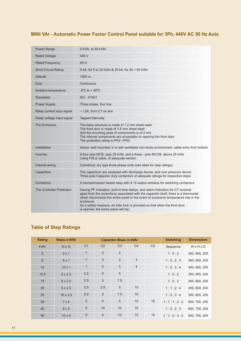
5 kVAr, to 50 kVAr
440 V
50 H
9 kA, for 5 to 25 kVAr & 25 kA, for 25 < 50 kVAr
1000 m
Continuous
-5 C to + 40 C
IEC - 61921
Three phase, four line
-- / 5A, from CT on line
Tapped internally
The basic structure is made of 1.2 mm sheet steel The front door is made of 1.6 mm sheet steel And the mounting plate of components is of 2 mm The internal components are accessible on opening the front door The protection rating is IP42 / IP52
Indoor, wall mounted, in a well ventilated non-dusty environment, cable entry from bottom
A four pole MCB, upto 25 kVAr, and a three - pole MCCB, above 25 kVArUsing FRLS cable, of adequate section
Cylindrical, dry type three phase units (see table for step ratings)
The capacitors are equipped with discharge device, and over pressure deviceThree pole Capacitor duty contactors of adequate ratings for respective steps
A microprocessor based relay with 4 / 6 output contacts for switching contactors
Having PF indication, built in time delays, and alarm indication for CT reversalapart from the protections associated with the capacitor itself, there is a thermostat which disconnects the entire panel in the event of excessive temperature rise in theenclosure. As a safety measure, an inter lock is provided so that when the front door is opened, the entire panel will trip.
0 0
Power Range
Rated Voltage
Rated Frequency
Short Circuit Rating
Altitude
Duty
Ambient temperature
Standards
Power Supply
Relay current input signal
Relay voltage input signal
The Enclosure
Installation
Incomer
Internal wiring
Capacitors
Contactors
The Controller Protection
Capacitor Steps in kVArRating
kVAr
5
8
10
12.5
15
20
25
35
40
50
Steps x kVAr
N x Q
5 x 1
8 x 1
10 x 1
5 x 2.5
6 x 2.5
8 x 2.5
10 x 2.5
7 x 5
8 x 5
10 x 5
C1
1
1
1
2.5
2.5
2.5
2.5
5
5
5
C2
2
2
2
5
5
2.5
5
5
10
5
C3
2
2
3
5
7.5
5
7.5
5
10
10
C4
3
4
10
10
10
15
15
C5
10
15
Switching
Sequence
1 : 2 : 2
1 : 2 : 2 : 3
1 : 2 : 3 : 4
1 : 2 : 2
1 : 2 : 3
1 : 1 : 2 : 4
1 : 2 : 3 : 4
1 : 1 : 1 : 2 : 2
1 : 2 : 2 : 3
1 : 1 : 2 : 3 : 3
Dimensions
W x H x D
300, 600, 200
300, 600, 200
300, 600, 200
300, 600, 200
300, 600, 200
300, 600, 200
300, 600, 200
500, 700, 200
500, 700, 200
500, 700, 200
MINI VAr - Automatic Power Factor Control Panel suitable for 3Ph, 440V AC 50 Hz Auto
Table of Step Ratings
18
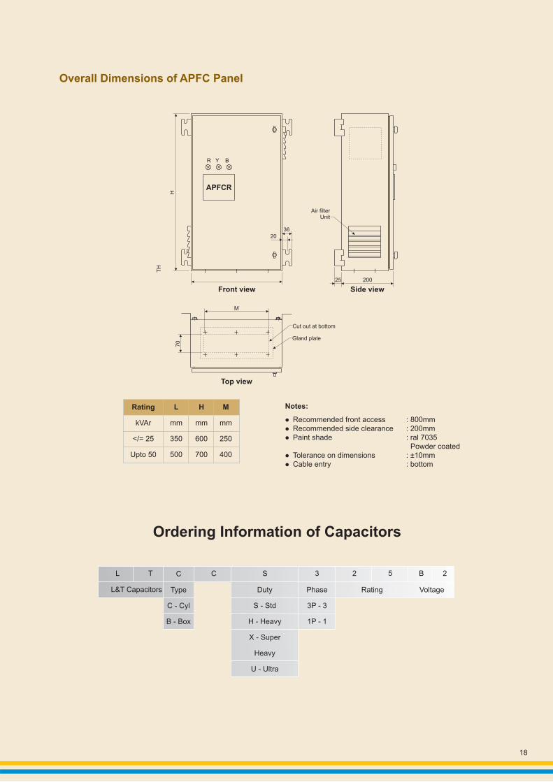
Ordering Information of Capacitors
L T C C S 3 2 5 B 2
L&T Capacitors Rating VoltageDuty
S - Std
H - Heavy
X - Super
Heavy
U - Ultra
Type
C - Cyl
B - Box
Phase
3P - 3
1P - 1
R Y B
APFCR
H
TH
3620
Front view
Air filterUnit
25 200
Side view
M
Cut out at bottom
Gland plate
70
Top view
Notes:
lRecommended front access : 800mmlRecommended side clearance : 200mmlPaint shade : ral 7035
Powder coatedlTolerance on dimensions : ±10mmlCable entry : bottom
Overall Dimensions of APFC Panel
Rating
kVAr
</= 25
Upto 50
L
mm
350
500
H
mm
600
700
M
mm
250
400

19
Overall Dimension
M12
16h
2±
FAST-ONTerminal 6.35 x 0.8
Discharge resistor assembly
d
Marking
Exp
an
sio
n to
h2
+a
±11
80
.5±
19
.6
16.7
h3
±
h3
+a
(e
xpa
nsi
on
)±
h3
+1
±
d 1±
(1)
d 1+4±
Label
Resistor Box Assembly
+1
16 M12 Toothed Locked
Washer DIN 6797-JB
Hexagon nut DIN 439-BM12Tightening torque
=12NM
Standard Duty
Cylindrical CapacitorsType
Ultra Heavy Duty
2
3
4
5
440
440
440
440
12
15
20
25
16
18
24
30
LTCCU312B2
LTCCU315B2
LTCCU320B2
LTCCU325B2
3.66.3
3.82.9
3.110.5
3.137
19
23.8
31.7
39.4
15.9
19.8
26.5
32.8
116.2
116.2
116.2
116.2
248
248
325
325
Sr.No
Power (Qn) (kVAr)
Voltage(Vn)
Capacitance(µf)
Rated current(A)
Dimensionin (mm)
Cat. Nos.
50Hz 60 Hz 50Hz 60 Hz D H
d = 2 ... 6 mm (depending on the capacitor type;
for details please refer to the data sheet)
Creepage distance 12.7 mm min.
Clearance 9.6 mm min.
1
TorqueT = 10 NmM12
Impregnating hole
TorqueT = 1.2 Nm
Marking
19
.60
.5±
d+
d1
16.8 0.5±
d
16
+1
h+
40
h
5±0
.5
d
1
2
3
4
5
6
7
8
9
10
11
440
440
440
440
440
440
440
440
440
440
440
1.0
2.0
3.0
4.0
5.0
7.5
10.0
12.5
15.0
20.0
25.0
1.2
2.4
3.6
5.0
6.0
9.0
12.0
15.0
18.0
25.0
30.0
LTCCS301B2
LTCCS302B2
LTCCS303B2
LTCCS304B2
LTCCS305B2
LTCCS307B2
LTCCS310B2
LTCCS3121B2
LTCCS315B2
LTCCS320B2
LTCCS325B2
5.5
11.0
16.5
22.2
27.5
41.0
55.0
68.5
82.2
110
137
1.31
2.62
3.94
5.25
6.56
9.8
13.1
16.4
19.7
26.2
32.2
1.57
3.15
4.72
6.30
7.87
11.8
15.7
19.7
23.6
31.5
39.4
53 x 117
53 x 117
63.5 x 130
63.5 x 130
63.5 x 154
75 x 162
75 x 198
75 x 270
75 x 270
90 x 270
90 x 270
Sr.No
Power (Q) kVArVoltage(V)
Capacitance(µf)
Rated current(A)
Dimension2
in (mm )Cat. Nos.
50Hz 60 Hz 50Hz 60 Hz D x H

20
1
2
3
4
5
6
7
440
440
440
440
440
440
440
7.5
8.0
10.0
12.5
15.0
20.0
25.0
9.0
9.60
12.0
15.0
18.0
24.0
30.0
LTBCS307B2
LTBCS308B2
LTBCS310B2
LTBCS312B2
LTBCS315B2
LTBCS320B2
LTBCS325B2
41.5
44.0
55.0
69.0
83.0
110.0
138.0
11.8
15.7
19.7
23.6
31.5
39.4
9.84
10.50
13.12
16.40
19.68
26.24
32.80
283
283
283
283
283
283
283
263
263
263
263
263
263
263
80
80
80
80
80
80
80
Sr.No
Voltage( Vn )
Capacitance(µf)
Rated current(A)
Dimensionsin (mm)
Cat. Nos.
50Hz 60 Hz 50Hz 60 Hz DH W
1
2
3
4
5
440
440
440
440
440
10
12.5
15
20
25
12
15
18
25
30
LTBCH310B2
LTBCH312B2
LTBCH315B2
LTBCH320B2
LTBCH325B2
55
68.5
82.5
110
137
15.7
19.7
23.6
31.5
39.4
13.1
16.4
19.7
26.2
32.8
325
325
325
325
375
263
263
263
263
263
80
80
160
160
160
Sr.No
Voltage(Vn)
Capacitance(µf)
Rated current(A)
Dimensionsin (mm)
Cat. Nos.
50Hz 60 Hz 50Hz 60 Hz DH W
Label
W
2 Slots 7 x 14
W1
90
D
H
Rubber Grommet Ø19mm for Cable Entry
Standard Duty
Heavy Duty
Box Type Capacitors
Power (Qn) (kVAr)
Power (Qn) (kVAr)
Heavy Duty
1
2
3
440
440
440
15
20
25
18
24
30
LTCCH315B2
LTCCH320B2
LTCCH325B2
83
110
138
23.6
31.5
39.4
19.68
26.24
32.8
280
280
280
Sr.No
Voltage(Vn)
Capacitance(µf)
Rated current(A)
Dimensionin (mm)
Cat. Nos.
50Hz 60 Hz 50Hz 60 Hz D H
100
116
116
Power (Qn) (kVAr)

Product improvement is a continuous process. For the latest information and special applications, please contact any of our offices listed here.
220210 SP 50481 R1
REGISTERED OFFICE ANDHEAD OFFICEL&T House, Ballard EstateP. O. Box 278Mumbai 400 001Tel: 022-6752 5656Fax: 022-6752 5858Website: www.Larsentoubro.com
ELECTRICAL STANDARD PRODUCTS (ESP)501, Sakar Complex IOpp. Gandhigram Rly. StationAshram RoadAhmedabad 380 009Tel: 079-66304007-11Fax: 079-26580491 / 66304025e-mail: [email protected]
38, Cubbon Road, Post Box 5098Bangalore 560 001Tel: 080-25020100, 25593613Fax: 080-25580525e-mail: [email protected]
131/1, Zone IIMaharana Pratap NagarBhopal 462 011Tel: 0755-4098706 / 7 / 8 / 9Fax: 0755-2769264e-mail: [email protected]
Plot No. 559, Annapurna ComplexLewis RoadBhubaneswar 751 014Tel: 0674-6451342, 2436696Fax: 0674-2537309e-mail: [email protected]
SCO 32, Sector 26-DMadhya Marg, P. O. Box 14Chandigarh 160 026Tel: 0172-4646841 to 7Fax: 0172-4646802e-mail: [email protected]
10, Club House RoadChennai 600 002Tel: 044-28462072 / 4 / 5 / 2109Fax: 044-28462102 / 3e-mail: [email protected]
67, Appuswamy RoadPost Bag 7156Opp. Nirmala CollegeCoimbatore 641 045Tel: 0422-2588120 / 1 / 5Fax: 0422-2588148e-mail: [email protected]
Electrical Standard Products (ESP) Branch Offices:
L&T House, Group MIG - 5PadmanabhpurDurg 491 001Tel: 0788-2213833 / 14 / 28 / 29Fax: 0788-2213820
A1/11, Astronauts AvenueBidhan NagarDurgapur 713 212Tel: 0343-2536891 / 8952 / 7844Fax: 0343-2536493e-mail: [email protected]
Milanpur Road, Bamuni MaidanGuwahati 781 021Tel: 0361-2651297Fax: 0361-2551308e-mail: [email protected]
II Floor, Vasantha Chambers5-10- 173, Fateh Maidan RoadHyderabad 500004Tel: 040-66720250Fax: 040-23296468e-mail: [email protected]
D-24, Prithvi Raj Road, C-SchemeJaipur 302 001Tel: 0141-2385916 / 8Fax: 0141-2373280e-mail: [email protected]
Akashdeep Plaza, 2nd FloorP. O. GolmuriJamshedpur 831 003JharkhandTel: 0657-2340864 / 387Fax: 0657-2341250e-mail: [email protected]
Skybright Bldg. M. G. RoadRavipuram Junction, ErnakulamKochi 682 016Tel: 0484-4409420 / 4 / 5 / 7Fax: 0484-4409426e-mail: [email protected]
3-B, Shakespeare SaraniKolkata 700 071Tel: 033-44002572 / 3 / 4Fax: 033-22822589e-mail: [email protected]
A28,Indira Nagar, Faizabad RoadUttar Pradesh,Lucknow 226 016Tel: 0522-2312904 / 5 / 6Fax: 0522-2311671e-mail: [email protected]
Plot No. 5184th Main RoadK. K. NagarMadurai 625 020Tel: 0452-2537404, 2521068Fax: 0452-2537552e-mail: [email protected]
EBG North Wing Office - 2Powai CampusMumbai 400 072Tel: 022-67052874 / 2737 / 1156Fax: 022-67051112e-mail: [email protected]
#12, Shivaji NagarNorth Ambazari RoadNagpur 440 010Tel: 0712- 2260012 / 3Fax: 0712- 2260020 / 30e-mail: [email protected]
32, Shivaji MargP. O. Box 6223New Delhi 110 015Tel: 011-41419514 / 5 / 6Fax: 011-41419600e-mail: [email protected]
L&T HouseP. O. Box 119191/1, Dhole Patil RoadPune 411 001Tel: 020-26135048Fax: 020-26124910, 26135048e-mail: [email protected]
3rd FloorVishwakarma ChambersMajura Gate, Ring RoadSurat 395 002Tel: 0261-2473726Fax: 0261-2477078e-mail: [email protected]
Radhadaya ComplexOld Padra RoadNear Charotar SocietyVadodara 390 015Tel: 0265- 2311744 / 6613610 / 1 / 2Fax: 0265-2336184e-mail: [email protected]
48-8-16, DwarakanagarVisakhapatnam 530 016Tel: 0891-6620411-2 / 3Fax: 0891-6620416e-mail: [email protected]
Electrical Standard ProductsLarsen & Toubro LimitedPowai Campus, Mumbai 400 072Customer Interaction Center (CIC)BSNL / MTNL (toll free) : 1800 233 5858Reliance (toll free) : 1800 200 5858Tel : 022 6774 5858Fax : 022 6774 5859E-mail : [email protected]: www.LNTEBG.com