reactive navigation of autonomous mobile robot using neuro-fuzzy system
TRANSCRIPT

M. M. Joshi & M. A. Zaveri
International Journal of Robotics and Automation (IJRA), Volume (2) : Issue (3), 2011 128
Reactive Navigation of Autonomous Mobile Robot Using Neuro-Fuzzy System
Maulin M. Joshi [email protected] Department of Electronics & Communications, Sarvajanik College of Engineering and Technology Surat,395001, India
Mukesh A Zaveri [email protected] Department of Computer Engineering Sardar vallabhbhai National Institute of Technology Surat, 395007, India
Abstract
Neuro-fuzzy systems have been used for robot navigation applications because of their ability to exert human like expertise and to utilize acquired knowledge to develop autonomous navigation strategies. In this paper, neuro-fuzzy based system is proposed for reactive navigation of a mobile robot using behavior based control. The proposed algorithm uses discrete sampling based optimal training of neural network. With a view to ascertain the efficacy of proposed system; the proposed neuro-fuzzy system’s performance is compared to that of neural and fuzzy based approaches. Simulation results along with detailed behavior analysis show effectiveness of our algorithm in all kind of obstacle environments. Keywords: Reactive Navigation, Mobile Robot, Neural Network, Behavior Analysis, Discrete Sampling
1. INTRODUCTION
Autonomous robot navigation means the ability of a robot to move purposefully and without human intervention in environments that have not been specifically engineered for it [1]. Autonomous navigation requires a number of heterogeneous capabilities like ability to reach a given location in real time to unexpected events, to determine the robot's position; and to adapt to the changes in the environment. For a mobile robot to navigate automatically and rapidly, an important factor is to identify and classify mobile robots' currently perceptual environment [1]. The general theory for mobile robotics navigation is based on a following idea: robot must Sense the known world, be able to Plan its operations and then Act based on the model. In spite of impressive advances in the field of autonomous robotics in recent years, it is still the area of an active research because of uncertainties involved due to unknown environments in real world scenarios. These uncertainties are due to following reasons [1]: no information or less information about a prior knowledge of an environment, lack of perceptually acquired information, limited range, adverse observation conditions, complex and unpredictable dynamics. It is also required that the behavior of the robot must be reactive to dynamic aspects of the unknown environments and must be able to generate robust behavior in the face of uncertain sensors, unpredictable environments and changing scenario. Many approaches have been proposed to solve the above mentioned challenges for autonomous robot navigation. Some of the approaches focus on path planning methods [2], few approaches use potential field [3] in which the robot-motion reaction is determined by the resultant virtual force. Several other methods have been used like statistical methods, Partially Observable Markov Decision Process (POMDP) [4] and reinforcement learning schemes [5]. In last few years, research in the domain is more focused with neural and fuzzy based artificial intelligence based approaches because of their ability to mimic human expertise.

M. M. Joshi & M. A. Zaveri
International Journal of Robotics and Automation (IJRA), Volume (2) : Issue (3), 2011 129
Humans have a remarkable capability to learn and perform a wide variety of physical and mental tasks via generalization of perceived knowledge. Neural network based approaches are used in robot navigation applications because neural network learns the humanoid expertise and then tries to mimic them by implementing in environment which may be similar or even different than used in its training (i.e. generalization). The attractive potential force attracts the robot toward the target configuration, while repulsive potential forces push it away from obstacles. The mobile robot is considered moving under the influence of resultant artificial potential field. The advantage of neural based approach lies in the learning capacity of the neural network. Performance of neural based system depends upon the effective training of its adjustable parameters (synaptic weights and bias parameters). Dahm et al. [6] have introduced a neural field based approach on robot ARNOLD. The approach was described by non linear competitive dynamical system. However, kinematics constraints were not considered for activation of set of artificial neurons. Zalama et. al. [7] have proposed reactive behavioral navigation of mobile robot using competitive neural network. The authors described various interconnected modules to generate wheel velocity using neural network. However, in such mechanisms many times learning convergence is very slow and generalization is not always satisfactory. A neural dynamics based architecture proposed by Yang and Meng [8]-[ 9] have discussed to reduce the computational complexity by avoiding learning procedures and also stability has been proven by lyapunov function and qualitative analysis. However, biologically inspired this neural method did not considered sensor information fusion and behavior combination. Some of earlier models are not found practical as they assumed that the whole workspace is definitely known considering only static environment. Humans’ capability to perform various tasks without any explicit measurements or computations is mimicked by fuzzy logic by providing formal methodology for representing and implementing the human expert's heuristic knowledge and perception based actions. Fuzzy logic based many approaches have been investigated in past years for controlling a mobile robot because of its capability to make inferences under uncertainty [10]. Artificial potential field approach has been proposed by Khatib[11] that discussed behavior based control. Saffoitti[12] has proposed fuzzy based methods for mobile robot navigation. Ismail and Nordin [13] have proposed reactive navigation by considering two separate fuzzy controllers for velocities and steering angle. In all these approaches, the purpose was restricted for fundamental and simple control actions. Fuzzy velocity control of mobile robot has been discussed by Mester [14]. However, only 10 heuristic fuzzy rules were used in their experiments. These approaches have inherent drawback that much efforts are needed to adjust tuning parameters and firing in advance. Intelligent navigation systems for omni directional mobile robots were described by Zavalang et.al.[15], which was influenced by potential field approach. Ishikawa [16] and Wei li et al.[17] have proposed behavior fusion for robot navigation in uncertainty using fuzzy logic. Both these approaches need improvements to handle complex environment. A system integrating techniques like dead–reckoning, self localization and environment are reported by Lee and Wu in [18]. In their approach membership functions and fuzzy rules were designed based on genetic algorithm. However, Genetic algorithm may not the best method for generation of rule base with 25 rules and priority based selection of heading directions does not take into account the behavior coordination and this algorithm focuses on direction control without considering velocity control. An obstacle avoidance approach using fuzzy logic has been proposed by Li and Yang [19]. A collision-avoidance approach using fuzzy logic is introduced by Lin and Wang [20] where, different modules e.g. Static-obstacle avoiding module, avoiding moving obstacle module and directing-toward-target module are created for the robot navigation. However, these modules are separately inferred and are not as coordinated as human reasoning. In mobile robots reactive navigation, key problem of local minima is addressed by Zhu and Yang [21] with state memory strategy; Wang and Liu [22] with minimum risk approach and by Xu and Tso [23] by considering π radian target switching. O.R.E. Motlagh et.al.[24] proposed virtual target switching strategy to resolve multiple dead end to improve the performance of earlier methods by considering three target states and six obstacle states resulting into 18 rules. However, with the limited number of rules such improvement not always guaranteed in dynamically changing environment with change in dead end shapes.

M. M. Joshi & M. A. Zaveri
International Journal of Robotics and Automation (IJRA), Volume (2) : Issue (3), 2011 130
To improve the performance, some neuro fuzzy methods have been proposed. Song and sheen [25] have considered heuristic fuzzy- neuro network to reactive navigation of mobile robot. In their approach, resulted velocity command enabled robot to move in an unknown environment using Fuzzy Kohonen Clustering Network (FKCN). However, their heuristic approach considered nine typical obstacle classes to formulate total 16 rules. Wei li et. al.[26] have proposed two level neuro-fuzzy architecture for behavior based mobile. In that approach, neural training has been done by four layer standard back propagation network and used only few selected examples to train neural network. However, in both above approaches; generalization of neural network for complete input space with limited training examples can not be guaranteed. Marichal et al. [27] have suggested an-other neuro fuzzy strategy by considering a three-layer neural network with a competitive learning algorithm for a mobile robot. The approach has been able to extract the information for fuzzy rules and the membership functions from human guided set of trajectories. For complex situations, it is difficult to optimally set required trajectories and hence resulted rules may not work well for generalization. Zhu and yang [28] have proposed five layer neuro-fuzzy controller considering neural networks to improve the performance of fuzzy network. The approach includes an algorithm to surpass redundant rules by observing the response of fuzzy network and removing rules with hamming distance lesser than specified threshold. However, this obviously requires training to mobile robot in given environment. However, for some critical operations like mining and under water operations, such training in given environment is never possible. Approaches without proper generalization will fail to take best decision when mobile robot needs to take immediate actions without any prior scanning of the given environment. Heuristic based approaches do not guarantee satisfactory performance for in general, difficult unknown environment space. In this paper, we propose two level neuro fuzzy based algorithm that overcomes the shortcoming of current approaches [25-28] in terms of learning mechanism used. In the proposed system, environment sense is done by neural network and behavioral control is executed by fuzzy system. Inputs to the neural network are outputs from multi sensors groups and heading angle. Output of neural network is reference heading angle that in connection with sensors data serves as input to fuzzy system. We propose discrete sampling based approach, in which optimal neural training is achieved by providing effective heterogeneity in training pairs while; retaining homogeneity in terms of providing different training pairs to the neural network. In our approach, we have generalized many parameters for robot navigation task like; number of sensors required for environmental sensing, arrangement of sensors, sensors grouping and quantization and heading angle inference. These make our approach unique and more generalized compared to approaches found in literature. Generalization of fuzzy based parameters enables us to select, to tune parameters as per requirements of given environmental conditions. Behavior based fuzzy systems used for mobile robot navigation demonstrate reasonably good performance; while navigating in cluttered and unknown environment The rest of this paper is organized as follows: the proposed algorithm for neuro-fuzzy based mobile robot navigation is discussed in Section 2, including range computation from given obstacles, sensors arrangement, grouping quantization and inference of heading angle. Section 3 descries neuro-fuzzy system for reactive navigation. Section 4 illustrates simulation results and detailed behavior analysis of neuro-fuzzy based mobile robot navigation. Finally concluding remarks are given in Section 5.
2. PROPOSED ALGORITHM In this section, we propose an algorithm for reactive navigation for a mobile robot using neuro-fuzzy based sys-tem. First, we describe the problem formulation for the motion planning problem. Let A be the single robot moving in a Euclidian space W, called workspace, represented as R
N,
with N= 2 or 3. Let B1, B2…Bq be the rigid objects distributed in W. The Bi’s are called obstacles. With assumptions that no kinematics constraints limit the motion of A in W, generate a path T specifying a sequence of positions and orientations of A avoiding contact with Bi’s, i.e. starting at the initial position and orientation and terminating at the goal position and orientation.

M. M. Joshi & M. A. Zaveri
International Journal of Robotics and Automation (IJRA), Volume (2) : Issue (3), 2011 131
2.1 Mobile Robot Configuration We consider two dimensional workspace (N=2) for mobile robot as shown in Figure.1. Mobile robot is having initial and target position coordinates denoted as (xo, yo) and (xt, yt) respectively. Mobile robot’s current position (calculated and updated at each step) can be denoted as (xcurr ,ycurr). Angle between target and positive y axis is θtr. Robot’s pose (head) with respect to positive y axis is considered as θhr and θhead is the heading angle between target and robot current position. Span (S) is the distance between left and right wheel. Vl and Vr are mobile robots left wheel and right wheel velocities, respectively.
FIGURE 1: Mobile Robot Configuration
The mobile robot has two independently driven co-axial wheels. We consider a mobile robot with differential drive wheels. Final target positions are known to the robot at all the time. At each step, current location and orientation are computed. No history of past sensor readings are retained and thus robot is having pure reactive navigation. Obstacles may be stationary or may be mobile. 2.2 Range Calculation of Mobile Robot From Given Obstacles Acquisition of precise range information of a mobile robot from each nearby obstacle is one of the most important tasks for robot navigation. Mobile robot needs to effectively sense surrounding environment. We have proposed an algorithm to find range information for robot navigation in presence of moving obstacles in our earlier work [29]. The important point is that because of presence of moving obstacles, prior geometry information may not help. But, our model acquires geometry information from sensed signals computed with the help of sensors mounted on robot. This makes our approach very general and can be used for any scenario. Following steps explains our algorithm to find out range of obstacle from robot A to Obstacle B:
Target
X-Axis
θhead
Robot
Y-Axis
Robot head
θtr
θhr
M. M. Joshi & M. A. Zaveri
International Journal of Robotics and Automation (IJRA), Volume (2) : Issue (3), 2011 132
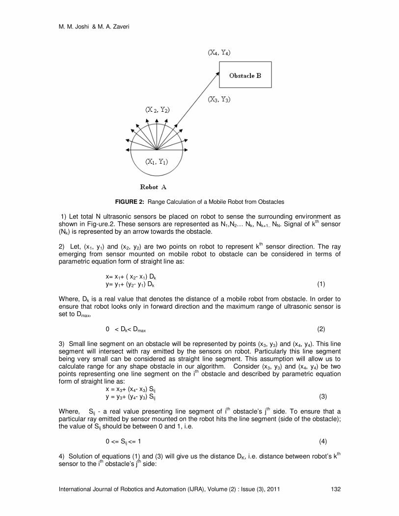
FIGURE 2: Range Calculation of a Mobile Robot from Obstacles
1) Let total N ultrasonic sensors be placed on robot to sense the surrounding environment as shown in Fig-ure.2. These sensors are represented as N1,N2… Nk, Nk+1.. NN. Signal of k
th sensor
(Nk) is represented by an arrow towards the obstacle. 2) Let, (x1, y1) and (x2, y2) are two points on robot to represent k
th sensor direction. The ray
emerging from sensor mounted on mobile robot to obstacle can be considered in terms of parametric equation form of straight line as: x= x1+ ( x2- x1) Dk y= y1+ (y2- y1) Dk (1) Where, Dk is a real value that denotes the distance of a mobile robot from obstacle. In order to ensure that robot looks only in forward direction and the maximum range of ultrasonic sensor is set to Dmax, 0 < Dk< Dmax (2) 3) Small line segment on an obstacle will be represented by points (x3, y3) and (x4, y4). This line segment will intersect with ray emitted by the sensors on robot. Particularly this line segment being very small can be considered as straight line segment. This assumption will allow us to calculate range for any shape obstacle in our algorithm. Consider (x3, y3) and (x4, y4) be two points representing one line segment on the i
th obstacle and described by parametric equation
form of straight line as: x = x3+ (x4- x3) Sij y = y3+ (y4- y3) Sij (3) Where, Sij - a real value presenting line segment of i
th obstacle’s j
th side. To ensure that a
particular ray emitted by sensor mounted on the robot hits the line segment (side of the obstacle); the value of Sij should be between 0 and 1, i.e. 0 <= Sij <= 1 (4) 4) Solution of equations (1) and (3) will give us the distance DK, i.e. distance between robot’s k
th
sensor to the ith obstacle’s j
th side:

M. M. Joshi & M. A. Zaveri
International Journal of Robotics and Automation (IJRA), Volume (2) : Issue (3), 2011 133
((y -y )*(x -x )-(y -y )*(x -x )) 4 3 1 3 1 3 4 3
((y - y )*(x -x )-(y -y )*(x -x ))2 1 4 3 4 3 2 1
DK
= (5)
5) Computation of the value of DK is to be carried out for each of total N sensors. For example, rectangle shaped n obstacles will have 4*n edges. For total N sensors, there will N* (4* n) size matrix computed at each step.
Sensors Grouping In our algorithm, we consider robot fitted with N ultrasonic sensors in the front. If the front (head) of the robot is at 0 degrees (w.r.t. +y axis), then the sensors are located between -90 to +90 degrees each being separated by θs =180/N degrees as shown in figure. 3(a).
FIGURE 3(a): Arrangement of ultrasonic sensors FIGURE 3(b): grouping of sensors
Sensors are grouped and final values are quantized before sending into the intelligent network. A sensor grouping will result into reduction of computational cost. In our algorithm, we sense unknown environment with N Sensors to extract more information about surroundings. At the same time, we resize sensors into M groups (M< N) before giving as input to intelligent system to reduce computational complexities still retaining the essence of more information. As the final value for each of M group, minimum value among the corresponding sensors readings are taken and then fed to intelligent system module. For figure.3 (b) Considering d(i)–ultrasonic data for ith sensor; distances to the obstacles may defined as below:
Left_obs = min{d (i)} where, i= 1,2…x. Front_obs = min{d (i)} where, i= x+1,x+2 …y. Right_obs = min{d (i)} where, i= y+1, y+2,.. N (6)
2.3 Quantization of Sensors Values In our approach, we perform quantization to provide discrete samples for neural training. Quantization formula for groups (Xi) where, i=1, 2...M (M<=N) is as follows: Xi = 1 for 0< di <=D1, 2 for D1 < di <=D2, 3 for D2 < di <=D3, ……………. . . Z for di >DZ. (7)

M. M. Joshi & M. A. Zaveri
International Journal of Robotics and Automation (IJRA), Volume (2) : Issue (3), 2011 134
Where, di is the minimum sensor value of the ith group and D1, D2 … DZ are threshold values for quantization.
2.4 Defining Heading Angle
We define heading angle (θhead) as follows:
• If θhead < p then θhead = α,
• If p <= θhead <= q then θhead =β,
• If θhead > q then θhead =γ (8)
Once surrounding environment sensing is completed; set of information is available for planning. Next step is to train intelligent system with these set of information. As stated earlier, neuro-fuzzy systems have abilities to learn and then perform intelligent task based on learning. Next subsection describes neuro-fuzzy based system.
3. NEURO-FUZZY SYSTEM FOR REACTIVE NAVIGATION Neural and Fuzzy based hybrid systems have been used in many applications in order to take advantage of individual systems. This motivates us to use combined neuro-fuzzy system for reactive navigation of a mobile robot in the presence of obstacles. We propose two stage, hybrid neuro-fuzzy system in which information from an environment (Sense) is obtained by neural networks while; more correct decisions (Act) are performed using a fuzzy system. As far as environment understanding (Sense) is concerned; neural network will be more effective candidate; as it gives computationally cost effective solutions than fuzzy system [30]. On the other had, we require tight control to exert final wheel velocity where fuzzy system would be better choice because of its functional mapping ability [31]. Our proposed framework provides an optimum learning of neural networks via discrete sampling that overcomes the problems faced by existing neuro fuzzy approaches based on experimental and heuristic bases training [25-28]. We consider two stages neuro-fuzzy based hybrid architecture as shown in Figure.4. In our proposed neuro-fussy system, the inputs from the sensors are fed to neural network which forms first stage of the proposed sys-tem and it is cascaded with a fuzzy system to generate final control action. First stage neural network has four inputs. Out of four inputs, three inputs are the distance information from the left, front and right obstacles pre-sent in robot’s perceptual environment. The fourth input is the heading angle. As an output, neural network generates Reference Heading Angle (RHA); an inferred angle than original head angle. During this process , as heading angle inference is already been processed by neural network and bettered with the support of local sensory data, resulted reference heading angle imparts better information to the subsequent fuzzy system than an actual heading angle. Heading angle is one of critical parameters and should be inferred correctly for reactive robot navigation. The neural network does this task and provides a reference heading angle as an output. In the second stage, fuzzy logic processes this information and drives the output wheels of mobile robot. Outputs of the system are left and right wheel velocities. Input sensory information’s cardinality for the neural and fuzzy networks can be shared or can be set to higher value for neural network to take maximum advantage of its learning capabilities.

M. M. Joshi & M. A. Zaveri
International Journal of Robotics and Automation (IJRA), Volume (2) : Issue (3), 2011 135
FIGURE 4: Two stage Neuro-Fuzzy System
3.5 Training Using Neural Network In our framework, neural network has M inputs (one per each of sensor group) derived from grouping of N sensors and giving the distance information about robot’s perceptual environment. One more input given to the neural network is the heading angle. Neural network processes these inputs and generates a reference heading angle. Neural networks have got remarkable generalization capabilities, once trained properly. Training of intelligent system is crucial for successful navigation of mobile vehicle. Generally, it is difficult to train such system as the input space may contain infinitely many possibilities and mobile robot needs to learn effectively for successful navigation. Many times mobile robot needs to execute operations in hazardous environments like fire or space missions where, online training is not feasible. Off line training is only possibility in such cases. Mobile robot needs to sense environment in real time and also to make precise decision based on learning. Various training approaches reported in literature are of following categories: a) generating training sequences by experimental set up as in [17] and b) heuristic approach based on expert rules [25]. In the first approach, the system learns by setting the different environmental set ups. i.e. different start, end (target) positions, different obstacles positions etc. In this case, the number of training patterns resulted for different input conditions may not be evenly distributed. Some of the input patterns may appear more number of times, while some may appear lesser or even may not appear. Training may not be considered optimum as; for some inputs patterns are not learnt while some are over learnt. In case of second alternative (training by expert rules [8]), training is per-formed using fewer number of input patterns. This type of training may save training time, may give good performance in some cases but, they may not perform well in all kind of environmental conditions. This is because of the fact that selection of training pairs is for a particular task and they do not represent entire space uniformly. In this paper, we propose mobile robot’s training based on discrete uniform sampling that overcomes the problems with above mentioned methods. The proposed algorithm not only takes samples from the entire sample space (to provide heterogeneity), also takes equal number of sample data from all possible input space (to pro-vide homogeneity). In the proposed algorithm,
M. M. Joshi & M. A. Zaveri
International Journal of Robotics and Automation (IJRA), Volume (2) : Issue (3), 2011 136
actual sensor readings are considered to be quantized in to n linguistic values. Uniform sampling of these quantized values will enable us a) to consider entire space of input region and; b) will enable us to generate optimum number of training pairs required for training. In the proposed approach, we train the network as follows:
1. Let input cardinality (number of inputs i.e sensors plus heading angle ) of the neural networks equal to M+1 and each input takes Z linguistic values (e.g. near, medium, far- as discussed in earlier section). Then we can generate total Z
M+1 training patterns.
2. Output values of each of these input patterns are decided based on experimentation or by expert rules.
3. Neural network is trained accordingly to training pairs generated and the performance of the network can be verified using a proper evaluating function e.g. MSE (mean square error).
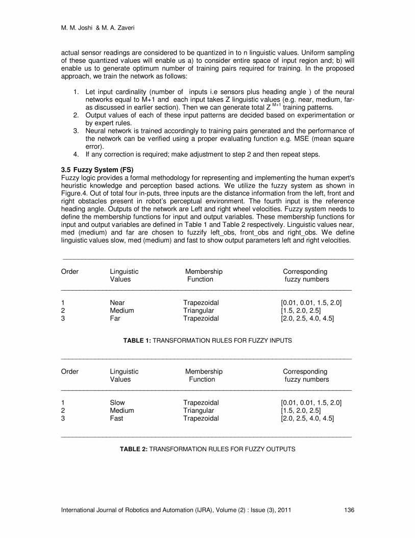
4. If any correction is required; make adjustment to step 2 and then repeat steps. 3.5 Fuzzy System (FS) Fuzzy logic provides a formal methodology for representing and implementing the human expert's heuristic knowledge and perception based actions. We utilize the fuzzy system as shown in Figure.4. Out of total four in-puts, three inputs are the distance information from the left, front and right obstacles present in robot’s perceptual environment. The fourth input is the reference heading angle. Outputs of the network are Left and right wheel velocities. Fuzzy system needs to define the membership functions for input and output variables. These membership functions for input and output variables are defined in Table 1 and Table 2 respectively. Linguistic values near, med (medium) and far are chosen to fuzzify left_obs, front_obs and right_obs. We define linguistic values slow, med (medium) and fast to show output parameters left and right velocities. _____________________________________________________________________________ Order Linguistic Membership Corresponding Values Function fuzzy numbers _____________________________________________________________________________ 1 Near Trapezoidal [0.01, 0.01, 1.5, 2.0] 2 Medium Triangular [1.5, 2.0, 2.5] 3 Far Trapezoidal [2.0, 2.5, 4.0, 4.5]
TABLE 1: TRANSFORMATION RULES FOR FUZZY INPUTS
_____________________________________________________________________________ Order Linguistic Membership Corresponding Values Function fuzzy numbers _____________________________________________________________________________ 1 Slow Trapezoidal [0.01, 0.01, 1.5, 2.0] 2 Medium Triangular [1.5, 2.0, 2.5] 3 Fast Trapezoidal [2.0, 2.5, 4.0, 4.5] _____________________________________________________________________________
TABLE 2: TRANSFORMATION RULES FOR FUZZY OUTPUTS

M. M. Joshi & M. A. Zaveri
International Journal of Robotics and Automation (IJRA), Volume (2) : Issue (3), 2011 137
3.5 Behaviors Fusion based on Fuzzy Reasoning Mobile robot moves in a given environment from start position to the end position. In order to avoid obstacles in its path, reactive navigation is performed in response to the sensor data perception. In order to coordinate different type of behaviors, various methods are available: i) priorities based data fusion ii) inhibiting strategy and iii) behavior based fuzzy reasoning. In priority based fusion, certain rules are always given priorities compared to others which may not be true always. In second case, when multiple rules are fired simultaneously, few rules are dominating and hence other rules are inhibited at the particular stage. In both the cases, enough attention may not be given to some rules which in turn may become critical after some period. In our work, we have used behavior based fuzzy reasoning in which all fired rules are given due weight age according to their firing level. For our proposed method, the following behaviors are realized: Target Steer, Obstacle Avoidance and Edge following. It is very difficult to acquire precise information about dynamic environments through ultrasonic sensors. A set of fuzzy logic rules to describe various behaviors are defined for the proposed system. Table 3 gives few samples of our defined fuzzy rules. These fuzzy rules show that the robot mainly adjusts its motion direction and quickly moves to the target if there are no obstacles around the robot. When the acquired information from the ultrasonic sensors shows that there are no obstacles to the left, front or right of robot, its main reactive behavior is target steer. When the acquired information from the ultrasonic sensors shows that there exist obstacles nearby robot; it must try to change its path in order to avoid those obstacles (i.e. Obstacle Avoidance behavior). When the robot is moving to a specified target inside a room or escaping from a U-shaped obstacle, it must reflect Edge Following behavior. If input then output
Rule no..
Fuzzy Behaviour
Left Obs.
Front Obs
Right Obs.
Head ang
Left Vel Right Vel
1 Target Steer Far Far Far Negative Low Fast
2 Target Steer Far Far Far Zero Fast Fast 3 Target Steer Far Far Far Positive Fast Low 4 Obstacle
Avoidance Near Near Far Negative
Fast Low
5 Edge Following
Far Far Near Positive
Med Med
TABLE 3: Fuzzy If-then rules
4. SIMULATION RESULTS In this section, we demonstrate the effectiveness, robustness and comparison of various systems for robot navigation using single stage neural network, single stage fuzzy system and our proposed hybrid neuro-fuzzy system. We have considered mobile robot having differential drive mechanism with span of mobile robot 50 cm. Total 9 ultrasonic sensors (N) are used for the study after comparing the results for 5, 9 and 15 no. of sensors and their effectiveness. These sensors are equally separated by θs = π/8 and detect the distance of obstacle along the radial direction up to 300 cm. The wheels can have a maximum velocity up to 30 cm/s. Input dimensions to the neural, fuzzy and neuro-fuzzy system are set to four. Dmin is set to 100 cm and Dmed is set to 200cm. In order to define heading angle (θhead), we have set the values of p, q, α, β, γ to -π/8, +π/8, 1, 2, and 3 respectively. For our simulation we use two layers feed forward back propagation network (FF- BPN) for mapping the input quantized values to the output. Batch mode of training is used for neural network. For neuro-fuzzy system, we have trained first stage neural network by considering 4 inputs as described earlier and each input takes 3 linguistic values (near (1), medium (2), far (3)). Hence,
M. M. Joshi & M. A. Zaveri
International Journal of Robotics and Automation (IJRA), Volume (2) : Issue (3), 2011 138
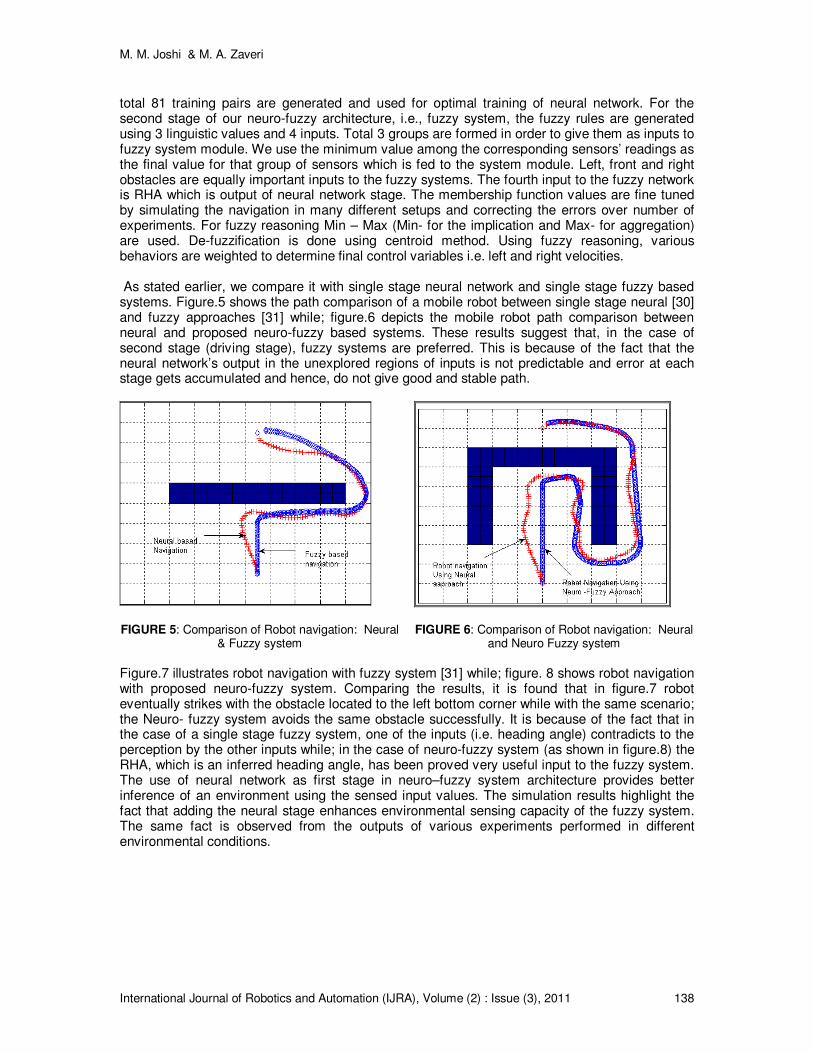
total 81 training pairs are generated and used for optimal training of neural network. For the second stage of our neuro-fuzzy architecture, i.e., fuzzy system, the fuzzy rules are generated using 3 linguistic values and 4 inputs. Total 3 groups are formed in order to give them as inputs to fuzzy system module. We use the minimum value among the corresponding sensors’ readings as the final value for that group of sensors which is fed to the system module. Left, front and right obstacles are equally important inputs to the fuzzy systems. The fourth input to the fuzzy network is RHA which is output of neural network stage. The membership function values are fine tuned by simulating the navigation in many different setups and correcting the errors over number of experiments. For fuzzy reasoning Min – Max (Min- for the implication and Max- for aggregation) are used. De-fuzzification is done using centroid method. Using fuzzy reasoning, various behaviors are weighted to determine final control variables i.e. left and right velocities. As stated earlier, we compare it with single stage neural network and single stage fuzzy based systems. Figure.5 shows the path comparison of a mobile robot between single stage neural [30] and fuzzy approaches [31] while; figure.6 depicts the mobile robot path comparison between neural and proposed neuro-fuzzy based systems. These results suggest that, in the case of second stage (driving stage), fuzzy systems are preferred. This is because of the fact that the neural network’s output in the unexplored regions of inputs is not predictable and error at each stage gets accumulated and hence, do not give good and stable path.
FIGURE 5: Comparison of Robot navigation: Neural & Fuzzy system
FIGURE 6: Comparison of Robot navigation: Neural
and Neuro Fuzzy system
Figure.7 illustrates robot navigation with fuzzy system [31] while; figure. 8 shows robot navigation with proposed neuro-fuzzy system. Comparing the results, it is found that in figure.7 robot eventually strikes with the obstacle located to the left bottom corner while with the same scenario; the Neuro- fuzzy system avoids the same obstacle successfully. It is because of the fact that in the case of a single stage fuzzy system, one of the inputs (i.e. heading angle) contradicts to the perception by the other inputs while; in the case of neuro-fuzzy system (as shown in figure.8) the RHA, which is an inferred heading angle, has been proved very useful input to the fuzzy system. The use of neural network as first stage in neuro–fuzzy system architecture provides better inference of an environment using the sensed input values. The simulation results highlight the fact that adding the neural stage enhances environmental sensing capacity of the fuzzy system. The same fact is observed from the outputs of various experiments performed in different environmental conditions.

M. M. Joshi & M. A. Zaveri
International Journal of Robotics and Automation (IJRA), Volume (2) : Issue (3), 2011 139
FIGURE 7: Robot navigation with single stage fuzzy system
FIGURE 8: Robot navigation with two stage Neuro-
Fuzzy system
FIGURE 9: Neuro-fuzzy based mobile robot navigation
Next subsection presents the detailed behavior analysis of proposed neuro-fuzzy based systems that highlights the effectiveness of our proposed system in given environment. A Various Fuzzy Based Behaviors and Heading Angle Consider mobile robot navigation for the case shown in figure.9. Mobile robot starts its journey from position “START” to the final position “F”. For a given scenario, mobile robot follows path from START-> A -> B -> C -> E -> F as shown in figure.9. Figure.10 shows mobile robot’s heading angle during its journey. Head-ing angle is the difference between target and head of the

M. M. Joshi & M. A. Zaveri
International Journal of Robotics and Automation (IJRA), Volume (2) : Issue (3), 2011 140
mobile robot and provides information about current head orientation. Initially, robot performs “Target steer” behavior and reaches to position “A” with “ZERO” heading angle, where it takes right turn which is a result of “avoid obstacle” behavior; and heading angle changes quickly to -90. There after, the robot follows the wall, i.e., the wall following behavior, and it reaches to “B”. At the same time, heading angle slightly varies from -90 to -100 degrees. At this point “B”, it takes right turn again (head angle (equal to α) changed to -180) and following the wall and reaches to “C” by decreasing heading angle (equal to β) further to -200 degrees. Mobile robot finds the end of the wall and perceives potential attraction by the target and takes left turn by avoiding contact with obstacle and reaches to “D”. During the same, the heading angle (equal to γ) starts increasing to -45 degrees. From position “D” to “E” it continues its quest to reach target following wall (heading angle (decreases slightly from -45 to -50 degree (δ)), finds opening at “E”. Finally mobile robot reaches from “E” to “F” with “target steer” behavior (first reducing head angle to near zero and then with almost zero head reaches target “F”).
FIGURE 10: Mobile robot’s heading angle
FIGURE 11: Left and right velocity control over time for mobile robot navigation
Speed Control of Mobile Robot In mobile robot navigation, speed control analysis gives information about and robot’s left and right velocities over the time. Figure.11 shows left and right wheel speed control. In differential drive mechanism, to take right turn; robot increases its left velocity and decreases right velocity and vice versa. As shown in figure11, from “START” position to point “A”, left and right velocities

M. M. Joshi & M. A. Zaveri
International Journal of Robotics and Automation (IJRA), Volume (2) : Issue (3), 2011 141
are found same. From “A” to “B” position (first, mobile robot takes right turn and then follows straight line). Hence, initially left velocity is higher than right velocity and then both almost being same till “B”. At “B” robot has left velocity higher again (avoid obstacle- right turn) and then with almost same left and right velocities (wall following) reaches “C”. Journey from “C” to “D” is with right velocity values higher than left velocity values (avoid obstacle /attraction potential - left turn). Mo-bile robot moves straight with same left and right velocity values (wall following) from point “D” to “E”. At last, at point “E”, right velocity values are more than left velocity values (right turn) and finally, it settles to point “F”. Target Distance and Distance Traveled Figure.12 shows mobile robot’s target distances and distance traveled over the time period for a case discussed in figure. 9. Start and target (F) coordinates for mobile robots are (10, 2) and (10, 18) respectively. For mobile robot From “START” to “A”, target distance is linearly decreased (START->A). When mobile robot finds an obstacle in between and trying to move out of the same, target distance is gradually increased again till “D” (A->B->C->D). Then onwards, target distance is again linearly decreased on path from D -> E -> F. Second graph in figure.12 shows the total distance traveled a curve with a linear rise from start to finish point. For the given situation, in presence of given obstacle scenario; mobile robot travels total 39.65 meters compared to 16 meters if it had traveled without any obstacles from START to F position (i.e. distance between (10, 2) and (10, 18) ) as shown in figure.9.
FIGURE 12: mobile robot’s target distance and distance traveled
M. M. Joshi & M. A. Zaveri
International Journal of Robotics and Automation (IJRA), Volume (2) : Issue (3), 2011 142
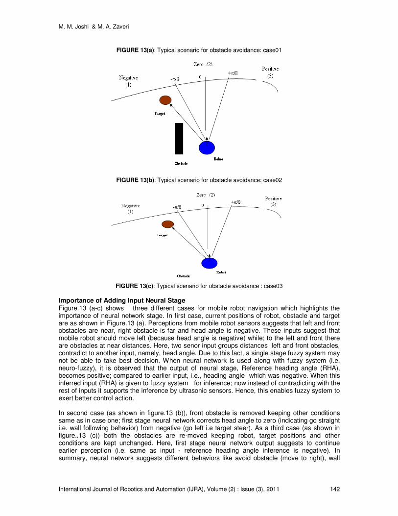
FIGURE 13(a): Typical scenario for obstacle avoidance: case01
FIGURE 13(b): Typical scenario for obstacle avoidance: case02
FIGURE 13(c): Typical scenario for obstacle avoidance : case03
Importance of Adding Input Neural Stage Figure.13 (a-c) shows three different cases for mobile robot navigation which highlights the importance of neural network stage. In first case, current positions of robot, obstacle and target are as shown in Figure.13 (a). Perceptions from mobile robot sensors suggests that left and front obstacles are near, right obstacle is far and head angle is negative. These inputs suggest that mobile robot should move left (because head angle is negative) while; to the left and front there are obstacles at near distances. Here, two senor input groups distances left and front obstacles, contradict to another input, namely, head angle. Due to this fact, a single stage fuzzy system may not be able to take best decision. When neural network is used along with fuzzy system (i.e. neuro-fuzzy), it is observed that the output of neural stage, Reference heading angle (RHA), becomes positive; compared to earlier input, i.e., heading angle which was negative. When this inferred input (RHA) is given to fuzzy system for inference; now instead of contradicting with the rest of inputs it supports the inference by ultrasonic sensors. Hence, this enables fuzzy system to exert better control action. In second case (as shown in figure.13 (b)), front obstacle is removed keeping other conditions same as in case one; first stage neural network corrects head angle to zero (indicating go straight i.e. wall following behavior) from negative (go left i.e target steer). As a third case (as shown in figure..13 (c)) both the obstacles are re-moved keeping robot, target positions and other conditions are kept unchanged. Here, first stage neural network output suggests to continue earlier perception (i.e. same as input - reference heading angle inference is negative). In summary, neural network suggests different behaviors like avoid obstacle (move to right), wall

M. M. Joshi & M. A. Zaveri
International Journal of Robotics and Automation (IJRA), Volume (2) : Issue (3), 2011 143
following (go straight) and target steer (continue left) in all three cases respectively. Inferences made by the neural stage, when in turn given as input to the subsequent fuzzy system, it strengthens fuzzy system’s local perception provided by the local sensors. Resulted neuro-fuzzy system performs better than single stage neural or single stage fuzzy systems. These results highlight the importance of adding a neural stage before the fuzzy control stage in the proposed system.
5. CONCLUSIONS In this paper, an approach for robot navigation using neuro-fuzzy based system is discussed. The mobile robot performs reactive navigation which is very useful for real time, dynamic environment rather than looking for an optimal path as performed by path planning techniques. Fuzzy system architecture for behavior based control of robot navigation gives better performance compared to neural based systems. Neural network’s output in the case of unexplored regions of inputs is not predictable and error at each stage is accumulated. As a result it does not lead to good and stable navigation path. The performance of mobile robot navigation system is improved by cascading the neural network and fuzzy system. The simulation results show that RHA provides better inference compared to original heading angle. The behavior based analysis of mobile robot navigation using the proposed neuro-fuzzy system demonstrates the excellent performance in complex and unknown environments. Simulation results for dynamic, complex and cluttered environment of mobile robot navigation space with neuro-fuzzy based architecture demonstrate good performance compared to most recent comparable approaches. This is because of our generalization of most of the parameters likes number of sensors, threshold values to measure distances and heading angles, optimum training using discrete sampling based approach for neural system training.
6. REFERENCES [1]G. Dudek and M. Jenkin. Computational Principles of Mobile Robotics, Cambridge university
press, 2000, pp. 01-40. [2]C.M. Clark & S. M. Rock. “Motion Planning for Multiple Mobile Robots using Dynamic
Networks”, Proc. of IEEE international Conference on Robotics and Automation, 2003, pp.4222-4227.
[3]A. Haddad, M. Khatib, S. Lacroix and R. Chatila. “Reactive Navigation in Outdoor Environment
using Potential Fields”, in proc. of IEEE international Conference on Robotics and Automation, 1998, pp. 1232-1237.
[4]G.Theocharous and S. Mahadevan. “Approximate planning with hierarchical partially
observable Markov decision process models for robot navigation”, IEEE International Conference on Robotics and Automation, 2002. Proceedings. ICRA'02. pp 1347– 1352.
[5]S.M.Chun, D.Y. Huang, C.H. Chou and C.C. Hsieh. “A reinforcement-learning approach to
robot navigation”, IEEE International Conference on Networking, Sensing and Control, 2004, pp. 665 – 669.
[6]P. Dahm, C. Bruckhoff and F. Joublin. "A neural field approach for robot motion control," IEEE
International Conference on Systems, Man, and Cybernetics, 1998, pp.3460-3465 [7]E. Zalama, J. Gomez, M.Paul and J.R. Peran. "Adaptive behavior navigation of a mobile
robot," IEEE Transactions on Systems, Man and Cybernetics, Part A: Systems and Humans, vol.32, pp.160-169, Jan 2002.
[8]S.X. Yang and M. Meng. "Neural network approaches to dynamic collision-free trajectory
generation," IEEE Transactions on Systems, Man, and Cybernetics, Part B: Cybernetics, vol. 31(3), pp.302-318, Jun 2001.
M. M. Joshi & M. A. Zaveri
International Journal of Robotics and Automation (IJRA), Volume (2) : Issue (3), 2011 144
[9]S.X. Yang and M. Meng. "Real-time collision-free motion planning of a mobile robot using a
Neural Dynamics-based approach," IEEE Transactions on Neural Networks, vol.14 (6), pp. 1541- 1552, Nov. 2003.
[10]J.C. Latombe. Robot Motion Planning, kluwer academic publishers- 1991. [11]M. Khatib, "Real-time obstacle avoidance for manipulators and automobile robots", Int. J. of
Robotics Research, vol.05 (1), 1986. [12]Saffiotti. ”The uses of fuzzy logic in autonomous robot navigation”, International journal on
Soft Computing”, vol. 1, pp. 180-197, 1997.
[13]I.I.Ismail and M.F. Nordin. "Reactive navigation of autonomous guided vehicle using fuzzy logic," Student Conference on Research and Development, 2002, pp. 153- 156.
[14]G. Mester, “Obstacle Avoidance and Velocity Control of Mobile Robots”, proceedings of 6th international symposium on intelligent Systems and Interpretation, Sep. 2008, pp.1-5.
[15]P.G. Zavlanga, S.G.Tzafestas , K. Althoefer , “Fuzzy Obstacle Avoidance and Navigation for Omni directional Mobile Robots”, ESIT, 2000.
[16]S. Ishikawa. "A method of indoor mobile robot navigation by using fuzzy control," Proceedings of Intelligent Robots and Systems IROS '91. vol.2, 3-5, 1991, pp.1013-1018.
[17]W. Li. “Fuzzy Logic based Perception-Action Behavior Control of a Mobile Robot in Uncertain Environments,” IEEE International Conference on AI, 1994, pp. 231-235.
[18]T. Lee and C. Wu. "Fuzzy Motion Planning of Mobile Robots in Unknown Environments,” presented at Journal of Intelligent and Robotic Systems, pp.177-191, 2003.
[19]H. Li and S. X. Yang. “A behavior-based mobile robot with a visual landmark recognition system,” IEEE Trans. Mechatronics, vol. 8, no. 3, pp. 390–400, Sep. 2003.1.
[20]C.H. Lin and L.L. Wang. “Intelligent collision avoidance by fuzzy logic control,” Robotics and Autonomous Systems, Volume 20, pp 61-83, 1997.
[21]A. Zhu and S.X. Yang. "A fuzzy logic approach to reactive navigation of behavior-based mobile robots," IEEE International Conference on Robotics and Automation, 2004. vol.5, no., pp. 5045- 5050.
[22]M.Wang and J.N.K.Liu. “Fuzzy logic based robot path planning in unknown environments”, in Proceeding of International Conference on Machine Learning and Cybernetics, Vol.2,2005,pp.813–818. 1.
[23]W.L. Xu, S.K.Tso and Y.H. Fung. "Sensor-based reactive navigation of a mobile robot
through local target switching," Proceedings of 8th International Conference on Advanced Robotics, ICAR '97, 1997, pp.361-366.
[24]E.O.Motlagh, T.S.Hong and N.Ismail. “Development of a new minimum avoidance system for
a behavior-based mobile robot,” Proceedings of international journal on Fuzzy Sets and Systems, Vol. 160,issue 13,pp.19129-1946,July 2009.
[25]K.T. Song. and L.H. Sheen. “Heuristic Fuzzy–neuro network and its application to reactive
navigation of a mobile robot,” International journal on Fuzzy Sets and systems Vol. 110, pp. 331-340, 2000.
M. M. Joshi & M. A. Zaveri
International Journal of Robotics and Automation (IJRA), Volume (2) : Issue (3), 2011 145
[26]W. Li, M Chenya and F.M. Wahl. “A Neuro- Fuzzy system architecture for the behavior based control of a mobile in unknown environment,” International journal on Fuzzy Sets and systems, Vol. 87, pp.133-140, 1997.
[27] G. N. Marichal, L. Acosta, L. Moreno, J. A. M´endez, J. J. Rodrigo and M. Sigut. “Obstacle
avoidance for a mobile robot: A neuro-fuzzy approach,” International journal on Fuzzy Sets and Systems, vol. 124, no. 2, pp. 171–179, Dec. 2001.
[28] Zhu and S.X. Yang. "Neuro fuzzy-Based Approach to Mobile Robot Navigation in Unknown
Environments," IEEE Transactions on Systems, Man, and Cybernetics, Part C: Applications and Reviews, vol.37, no.4, pp.610-621, July 2007.
[29] M.M.Joshi and M.A. Zaveri. “Neuro-Fuzzy Based Autonomous Mobile Robot Navigation”,
IEEE 11th International Conference on Control, Automation, Robotics and Vision, ICARCV 2010 , Singapore, Dec 2010.
[30] M.M.Joshi and M.A. Zaveri. “Optimally learnt, neural network based autonomous mobile
robot navigation system”, International Conference on Advances in Electrical & Electronics , AEE 2010 , 20-23 December 2010.
[31] M.M.Joshi and M.A. Zaveri. “Fuzzy Based Autonomous Mobile Robot Navigation”, IEEE
India Conference INDICON2009, Dec. 2009.