reactive mixing of silica and rubber for tyres and engine mounts
TRANSCRIPT

Adhesion of RFL-treated cords to rubber
New insights into interfacial phenomena
The studies described in this thesis are part of the Research Pogramme of the Dutch Polymer Institute, P.O. Box 902, 5600 AX Eindhoven, The Netherlands, project nr. #459 Adhesion of RFL-treated cords to rubber: new insights into interfacial phenomena By W.B. Wennekes Ph.D. thesis, University of Twente, Enschede, the Netherlands, 2008 With references – With summary in English and Dutch Copyright © W.B. Wennekes, 2008 All rights reserved Cover design by W.B. Wennekes Part of the research described in this thesis was performed at the facilities of Teijin Aramid B.V. in Arnhem, the Netherlands. Printed by Print Partners Ipskamp, P.O. Box 333, 7500 AH, Enschede, the Netherlands ISBN 978 90 365 2588 6

ADHESION OF RFL-TREATED CORDS TO RUBBER
NEW INSIGHTS INTO INTERFACIAL PHENOMENA
PROEFSCHRIFT
ter verkrijging van de graad van doctor aan de Universiteit Twente,
op gezag van de rector magnificus, prof. dr. W.H.M. Zijm,
volgens het besluit van het College voor Promoties in het openbaar te verdedigen
op vrijdag 18 januari 2008 om 15.00 uur
door
Wilco Bernardus Wennekes
geboren op 25 april 1979 te Doetinchem

Dit proefschrift is goedgekeurd door: Promotor : prof. dr. ir. J.W.M. Noordermeer Assistent promotor : dr. R.N. Datta

Voor mijn vader en moeder


Table of contents
Chapter 1 Introduction: cord-rubber composites 1 Chapter 2 Literature survey: adhesion of fibre materials to rubber
compounds 7
Chapter 3 Influence of the rubber curatives on rubber properties and
adhesion to RFL-treated aramid cord 31
Chapter 4 Curative migration from rubber into the RFL-dip film 53 Chapter 5 Investigations into the migration pattern of curatives, in relation to
the adhesion between RFL-treated cords and rubber compounds 73
Chapter 6 Influence of vinylpyridine monomer content of the RFL latex on
mutual adhesion between treated cords and rubber compounds 95
Chapter 7 Interaction between RFL and rubber: a model compound
vulcanisation study 113
Chapter 8 Mechanism of curative migration from rubber to RFL-dip 129 Chapter 9 Summary and evaluation of the results 149 Samenvatting 155 Symbols and abbreviations 161 Bibliography 163 Curriculum vitae 167 Dankwoord 169

Chapter 1
Introduction: cord-rubber composites
A brief introduction is given about the importance of cord-rubber composites. The example of a car-tyre shows that the cords carry all the loads that a tyre is subjected to; this is illustrated by a comparison between bias and radial tyres. The adhesion between cords and rubber is very important with regard to safety as well as durability of tyres. In this chapter, the objective of the project is defined and a description of the setup of the thesis is outlined.

Chapter 1
1.1 INTRODUCTION
Cord-rubber composites can be found in every day life. Examples of
applications are car- and bicycle tyres, high-pressure hoses and conveyor belts. Some essential under-the-hood applications are made of cord-rubber composites as well: timing belts, V-belts and radiator hoses are examples. By far the largest of all these examples is the car tyre. The application of cords in tyres is essential because the cords prevent large deformations of the rubber material when excessive forces are applied. These forces are caused by the air pressure of the tyre, and by accelerating, breaking and cornering of the car. The network of cords that provides the tyre with its strength and its shape is called the carcass. There are two types of carcass constructions in use, thereby dividing virtually all tyres in two categories: radial and bias tyres, Figure 1.1.1
A
B
Figure 1.1 Schematic representation of the two tyre constructions: bias (A) and
radial (B)1 1.1.1 Bias tyre construction
The oldest tyre construction is called bias or cross ply: Figure 1.1A. A bias tyre has a casing which is made of stacked reinforcing layers of cords, called plies, crossing over each other at an angle of 30° to 40° to the centre line of the tyre. These stacked plies reinforce both the tread and the sidewall and must therefore resist the forces caused by cornering, accelerating and breaking, but also maintain the shape of the tyre. Because of the required flexibility of the tyre sidewall, the all-sided reinforcement causes the tread to deform as well when driving over obstacles. This causes rapid wear, lower traction and higher fuel consumption compared to more recent radial tyres. 1.1.2 Radial tyre construction
The first commercial tyre with radial belt construction was produced by Michelin in 1948: the ‘Michelin X’. A schematic reproduction of a radial tyre carcass is shown in Figure 1.1B. Textile cords are placed at 90° to the direction of travel from bead to bead, designed to hold the air pressure and carry the load of the car. These cords are flexible and large deflections are allowed to absorb obstacles on the road for comfort. However, positioning the reinforcing
2

Introduction
cords in this direction, there is insufficient stabilisation of the circumference of the tyre, and the control and steering properties would be completely unacceptable. Therefore, additional plies of high modulus cords, usually steel, are placed at an angle of 16° to 25° underneath the tread. These plies are designed to carry the load caused by accelerating, breaking and cornering. The radial tyre separates the functions of the tread and the sidewall, where the bias tyre compromises the two. 1.1.3 Safety issues regarding tyres
A proper reinforcement of a tyre is essential, not only for comfort and handling, but the tyre is also an important part of the car regarding safety. Even under extreme conditions, low tyre pressure, hot weather or during an emergency break, the tyres must remain intact since it represents the connection between the car and the road. Actually, with modern porous asphalt (Dutch: “ZOAB”) road coverage, the real contact surface between tyre and road is of the size of a large postal stamp.2 This clearly illustrates the sensitivity of this technology for safety.
In 2001, certain types of Firestone tyres installed on Ford Explorer SUV’s, separated causing the vehicles to tumble. In the USA, this caused 174 deaths, more than 700 injuries and around 6000 complaints of tyre blow-outs at highway speeds.3 Most of the accidents happened in the warm southern states.4 For both Ford and Firestone the financial damage was enormous, because of the lawsuits involved5 and the need to recall nearly 20 million tyres and more than 100.000 cars6, 7: see the newspaper article in Figure 1.2. Firestone blamed Ford for advising a too low tyre pressure and Ford blamed Firestone for using dried-out rubber, resulting in insufficient adhesion between the tyre tread and the rest of the tyre.3 The Ford/Firestone incident illustrates the importance of tyres regarding vehicle safety and thereby the importance of good adhesion between all the tyre parts. Because the reinforcing cords carry all the loads where the tyres are subjected to, sufficient adhesion between rubber and cords is therefore indispensable to transfer the loads from rubber to cord effectively; not only for the new tyre, but throughout its whole life, which may last more than 10 years under often adverse conditions.
3

Chapter 1
Figure 1.2 Article in the New York Times from May 21st 2001
1.2 AIM OF THE RESEARCH IN THIS THESIS
Textile cords used in rubber applications are commonly treated with a so-called Resorcinol Formaldehyde Latex (RFL) dip. Despite the relevance of good adhesion between cords and rubber, and although this system dates back as far as 19388 and is still commonly used for rubber reinforcement till today, the mechanism by which the adhesion is obtained has remained unclear. The level of knowledge of adhesion between RFL-treated cords and rubber today is empirical rather than scientific. With new and stronger fibre materials introduced in recent years, in particular aramid fibres, it was considered appropriate to revisit the fibre-rubber adhesion technology to obtain more fundamental knowledge of the physical and chemical processes involved in the adhesion between RFL-treated cords and rubber. 1.3 STRUCTURE OF THIS THESIS
A literature survey on cord-rubber composites is presented in Chapter 2. The focus is on research published on the standard RFL treatment and the double dip treatment used for aramid and polyester cords to enhance the adhesion with rubber compounds.
In Chapter 3, a study is described regarding the influence of rubber curatives in the rubber compound on vulcanisates properties, as well as on the
4

Introduction
adhesion to RFL-treated aramid cords. The amounts of the rubber curatives are varied using an experimental setup obtained by Design of Experiments.
A Scanning Electron Microscope coupled to an Energy Dispersive X-ray spectrometer (SEM-EDX) is used to analyse the interfaces between rubber compound and RFL-dip, as reported in Chapter 4. The technique SEM-EDX is a local elemental analysis and, because the amount of rubber curatives is varied in the rubber, the distribution of the atoms sulphur and zinc through this interface is of particular interest.
Several attempts to change the atomic sulphur distribution in the RFL-rubber interface and to measure the effect on the adhesion are described in Chapter 5.
The influence of the type of latex used in the RFL formulation, on the adhesion to several rubber compounds, is the subject of Chapter 6. The influence of vinylpyridine as co-monomer in the latex is studied.
Chapter 7 deals with a model compound vulcanisation study with squalene as a model. The physical interaction between model compounds and ground RFL powder at different stages of vulcanisation is determined.
The exact migrating species, as well as the moment the formation of these species takes place during vulcanisation of real rubber systems are described in Chapter 8 because these species turn out to be the crucial players in adhesion development.
In Chapter 9 this thesis is completed by summarising and evaluating the results.
1.4 REFERENCES 1. T. French, "Tyre Technology". 1988, New York: Adam Hilger. 2. Private communication Continental Tyres, Hannover, Germany. 3. J. Hadley, Safety remains an issue with tyres, in "Seattle Post-
Intelligencer". 2001, June 4. 4. Website available from: http://nhsta.dot.gov. 5. J. Vertuno, Firestone to pay $6.5 million to woman's family, in "Seattle
Post-Intelligencer". 2001, August 20. 6. K.N. Gilpin, Firestone to recall 3.5 million more SUV tires, in "The New
York Times". 2001, October 1. 7. K. Bradsher, After a century, Firestone halts tire sales to Ford, in "The
New York Times". 2001, May 21. 8. W.H. Charch, N.Y. Buffalo, and D.B. Maney, (US2128635) DuPont,
1938.
5

Chapter 1
6

Chapter 2
Literature survey: adhesion of fibre materials to rubber compounds
the RFL-treatment are escribed: fibre surface roughening, adhesion promoter additives to the rubber ompound, impregnated fibres and plasma treatment.
The present chapter provides an overview of literature published on fibre/rubber composites. A brief history of fibres used in rubber applications is given, but the emphasis is on the adhesion between fibre materials and rubber compounds. Extra attention is given to the standard RFL-treatment and the double dip treatment used for aramid and polyester fibres to enhance the adhesion with rubber compounds. Some alternatives todc

Chapter 2
2.1 INTRODUCTION
Fibre reinforced rubber compounds play a crucial role in (high-pressure)
hoses, transmission belts, conveyor belts and tyres. Until about 1890, only natural fibres were available. Just before the end of the 19th century the first synthetic fibres based on cellulose were developed. Cellulose is an insoluble substance and in order to make this soluble, several derivations were tried. The first attempt was nitration, but cellulose nitrate proved to be more useful as guncotton than as a fibre. Cooper rayon and viscose rayon followed1; the latter became the first large-volume synthetic fibre material. These cellulose yarns are considered to be half-synthetic, because the raw material is still a natural polymer: cellulose. DuPont developed the first fully synthetic fibre Nylon® 66 or Polyamide 66; it was commercially introduced in 1936 (Carothers). A few years later, Polyamide 6 (Schlack, 1941) and Polyester (Whinfield & Dickson, 1942) were introduced. The development of “advanced fibres” took place around 1970. Most of these fibres were produced from fully aromatic polymers with high temperature stability. Eventually, this led to the discovery of the liquid-crystalline behaviour of PPTA (paraphenylene terephthalamide), the first super-strong fibre. The companies DuPont and Akzo Nobel started a patent conflict in 1979. The patents of DuPont2-5 as well as the patent of Akzo Nobel6 were necessary to produce this fibre. In 1988, the two companies reached a compromise. Nowadays, the PPTA fibre of DuPont is called Kevlar®. Akzo sold its fibre division and the PPTA fibre is now owned by Teijin; the brand name is Twaron®. The second super-strong fibre was gelspun polyethylene (Dyneema® of DSM, 1979).
The types of fibres used for reinforcing rubber are listed in Table 2.1, together with the year the fibre was invented and the year it was introduced in tyre reinforcement. Table 2.1 Types of fibres produced throughout history for tyre reinforcement
Type of fibre Year of invention Introduction in tyre reinforcement7
Cotton app. 7000 years ago 1900 Viscose rayon 8 1885 1938 Polyamide 669 1935 1947 Polyamide 610 1938 1947 Polyethylene terephthalate11 1941 1962 Aromatic polyamide2-6 1969 1974 Gelspun polyethylene12 1979 -
8

Literature survey
Table 2.2 Type of fibres used in tyres13
Tyre type Tyre part
Standard High performance
Ultra high performance (>300 km/h)
Racing Run flat Ultra light
Carcass PET Rayon
PET Rayon
Rayon Aramid
PEN
Rayon Aramid
Rayon Rayon & steel
PET
Rayon Aramid
Belt Steel Steel Aramid
Steel PEN Aramid Steel Aramid
Capply no Polyamide Aramid
Polyamide Aramid
Polyamide Aramid
Polyamide Aramid
Polyamide Aramid
Chafer no Polyamide Aramid
Polyamide Aramid Aramid Polyamide Aramid
Bead Steel Steel Steel Steel Aramid Steel Steel
Aramid
Figure 2.1 Cross section of a tyre, indicating the areas important for fibre
reinforcement
In Table 2.2, the types of fibres used in various parts of tyres are listed. In Figure 2.1, a cross section of a tyre is shown with the description of the various tyre parts. The types of fibres used in tyres are limited to polyamide, rayon, polyester, aramid and steel, because these materials are sufficiently temperature-resistant to survive the vulcanisation step in tyre manufacturing without weakening or complete disintegration. There is a large variety between these fibres in price and performance, hence the change in type of reinforcement with increasing demands. The main properties of the fibres are listed in Table 3.3.
9

Chapter 2
Table 3.3 Properties and performance of several types of fibres
Rayon Polyamide 6 Polyamide 66 Polyester Aramid Density (kg/m3) 1520 1140 1140 1380 1440 Moisture content* (%) 12-14 4 4 0.4 1.2-7 Decomp. temp (°C) 210 - - - 500 Melting temp. (°C) - 255 255 285 - Glass transition temperature (°C) - 50 57 69 >300
E-mod (cN/tex) 600-800 300 500 850 4000 Tensile strength (MPa) 685-850 850 850 1100 2750 * measured at 65% relative humidity at 20°C
The properties of Rayon were significantly improved between the 1930’s and the 1970’s. This was realised by making the Rayon denser and more uniform in structure. A major disadvantage of Rayon is its sensitivity to moisture. In moist conditions, its loss in strength is significant.
Polyamide 6 is mostly used in automobile tyres in India and South America; polyamide 66 is used on a larger scale. For rubber reinforcement, polyamide 6 and polyamide 66 have the disadvantage of a low melting point and a low modulus. Therefore, they cannot be used in the carcass but only as a capply, above or around the steel belt.
Polyester fibres have a high modulus and a high tensile strength and are the single most important reinforcing material for tyres. However, there are two problems involved in using polyester for reinforcing rubber. The first problem is that polyester is chemically rather inert and it is therefore more difficult to obtain a sufficient level of adhesion to rubber compared to rayon and polyamide. The second problem is the thermal shrinkage. Various grades of polyester are available with varying shrinkage/modulus ratios.
Aramid fibres have a very high modulus and tensile strength. However, this is coupled to a very low value of elongation at break. The major disadvantage of this low elongation occurs when aramid is used in several layers. When flat, each layer contributes its own share of strength, but upon bending the outer layer causes a compression deformation of the inner layers: aramid performs poorly under compression. The elongation at break of an aramid fibre can be improved by applying a large twist factor. Next to this, there is the problem of poor adhesion, similar to polyester. 2.2 STANDARD ADHESIVE TREATMENTS OF FIBRES
When using fibres in combination with rubber, good adhesion is essential especially for high safety products such as tyres. The adhesion between untreated fibres and rubber is always low, because there is a significant difference in modulus and polarity between the reinforcing fibres and the rubber matrix. The type of adhesive treatment is dependent on the type of fibre used. In the case of cotton, one of the first fibres used in rubber, the only
10

Literature survey
adhesive treatment necessary is drying the fibre. Cotton fibres are not smooth; filaments are sticking out of the surface of the fibre. These filaments are anchored in the rubber matrix. The frictional forces that need to be overcome to pull or strip the fibre out of the rubber result in a significant adhesion.
The (semi) man-made fibres such as regenerated cellulose and polyamide have a smooth surface; therefore, there is no interlocking of filaments. Furthermore, the mechanical properties of these fibres are higher compared to cotton and therefore a higher strength of the adhesion is required. This resulted in the Resorcinol Formaldehyde Latex treatment invented by W.H. Charch and D.B. Maney.14 For polyester fibres, the RFL-treatment alone is not sufficient due to the lack of polar and hydrogen bonding groups in its chemical structure. In case of aramid fibres, the bulky aromatic groups sterically hinder the amide functionalities. Therefore, both polyester and aramid fibres are treated with a predip before being treated with a standard RFL-dip. An outline of the RFL-treatment is schematically depicted in Figure 2.2. In the following part this RFL-scheme will be elaborated in more detail.
ResorcinolFormaldehyde
NaOHWater
Maturation
Resin solution
Further maturation
RFL
FiberDipping
RFL Cure
Rubber compound Vulcanization
Predip
Predipcure
LatexWater
DippingFiber
RayonPolyamide
PolyesterAramid
Figure 2.2 Schematic representation of the various fibre treatments, including
RFL-treatment and the adhesion to rubber compounds 2.2.1 RFL composition
The RFL-dip is an emulsion of a rubber latex in a solution of resorcinol and formaldehyde in water. If latex alone would be applied to the cords, it would provide an interaction with the rubber matrix of the compound but not with the fibre itself; furthermore, the latex layer would have weak mechanical properties.
11

Chapter 2
By adding resorcinol and formaldehyde, the dip layer increases in polarity and mechanical properties.
The preparation of a RFL-dip takes place in two stages. First, an aqueous solution of resorcinol and formaldehyde is matured for several hours at room temperature. By adding sodium hydroxide, this mixture becomes basic. During the maturation process, some degree of condensation takes place. Second, the resin solution is added to a mixture of latex and water. The amount and ratio of latex and water can be varied to achieve the desired RFL-dip. A typical RFL formulation is given in Table 2.4; a RFL-dip has a typical solid content of around 20 wt% and a pH of around 10. Table 2.4 typical RFL formulation
Dry parts/100 parts of dry latex Resin solution Resorcinol 11.2 Formaldehyde 6.3 Sodium hydroxide 0.7 Total 18.2 Final RFL-dip VP-latex 100 Resin solution 18.2 total 118.2
Instead of formaldehyde and resorcinol, often penacolite is used. Penacolite is the linear polymer of the two monomers; it is acid polymerised with a molecular weight of around 300 g/mol. When the dip is prepared, extra formaldehyde and sodium hydroxide or ammonium hydroxide are added to obtain the required pH and formaldehyde/resorcinol ratio for the three-dimensional resin network formation. The major advantage of using penacolite is that the maturation of the resin solution is no longer required.
Several studies have shown that the structure of the cured RFL consists of a continuous resin phase and dispersed latex particles.15, 16 A visualisation of the morphology is shown in Figure 2.3.
12

Literature survey
OH
OHCH2
CH2
OH
CH2
OHOH
CH2
OH
CH2
OH
CH2
CH2
OHOH
OHCH2
OH
OHCH2
CH2 OH
OH
CH2
OH
OH
CH2
CH2
OH
OHCH2
OH
OH
OH
OHOH
CH2
OH
OHOHCH2
OH
OH
OH
CH2OH
OH
OHCH2
CH2OH
OH
OHCH2
OHCH2
OH
OH
Latex Latex
Latex
Figure 2.3 Proposed RFL morphology
2.2.2 The dipping parameters
A general scheme for a dipping process unit is given in Figure 2.4. In this picture, the cord is moving from the right to the left. When a feed roll is empty, the entry accumulator is used to gain time to attach a new feed roll. Before entering the impregnator bathes and after the ovens, series of rolls are present. These rolls have a relative velocity between each other, allowing application of a certain stress on the cord during dipping and drying. After the cord has passed an impregnator bath, the amount of dip on the cord (dip pickup) is regulated by the so-called pickup control system. This is mostly a squeeze roll unit, but can also be a vacuum unit or a beater. The second dipping unit functions similar to the first one. The exit accumulator works the opposite way as the entry accumulator, as a buffer for the rebatch unit. Parameters that are adjusted during the dipping process are: cure temperature of the predip, cure temperature of the RFL-dip, tensile forces on the cord when passing the ovens and residence times in the ovens. The residence times in the ovens can be adjusted either by changing the speed of the cord or by adjusting the number of loops which the cord makes through the ovens.
All these parameters need optimisation for every type of reinforcing fibre, the type of RFL and the type of rubber to adhere to. It is therefore not surprising that the knowledge of cord to rubber adhesion to date is very pragmatic rather than scientific.
13

Chapter 2
Figure 2.4 General layout of a fabric treatment unit for a two dip system17
Many RFL variables such as formaldehyde to resin ratio, resin to latex
ratio, dip pickup, acidity of the dip, cure time and temperature of the dip and environmental aspects such as UV and ozone attack were investigated and their influence on the adhesion reported in a variety of papers.18-28 The references reported here only represent a selection of the most useful articles. Formaldehyde to resorcinol ratio: - Formaldehyde and resorcinol react in a similar manner as in the formation of Bakelite.29 The reactions take place in a basic environment. The reaction scheme is depicted in Scheme 2.1.
OH
OHNaOH
O
OH
Na+
OH2
O
OH
C
O
OH
C
O
OHCH2
OO
OH
HCH2
O
O
OH
CH2
OH
O
OH
CH2
O
OH
CH2
O
OH
O
OH
CH2
O
OH
+ +
+
+
OH
OHNaOH
O
OH
Na+
OH2
O
OH
C
O
OH
C
O
OHCH2
OO
OH
HCH2
O
O
OH
CH2
OH
O
OH
CH2
O
OH
CH2
O
OH
O
OH
CH2
O
OH
+ +
+
+
Scheme 2.1 Reaction of formaldehyde and resorcinol in a basic environment
14

Literature survey
Increasing the amount of formaldehyde increases the rate and amount of methylol formation. Due to this methylol functionality, reaction can take place with another resorcinol molecule according to the scheme. Increasing the formaldehyde to resorcinol ratio increases both the degree of condensation and the degree of branching. The concentration, the maturation time and temperature of the resin solution, as well as the curing time and temperature of the RFL-dip influence the rate of condensation.
The influence of the formaldehyde to resorcinol ratio of the RFL-dip on the adhesion to rubber compounds has been the subject of various review articles in the 1950’s and 60’s. All studies indicate an optimum in formaldehyde and resorcinol ratio as shown in Figure 2.5. Porter22 studied the effect, using a styrene butadiene (SBR) rubber compound containing N-tert-butyl-benzothiazole sulphenamide (TBBS), tetramethyl thiuram disulphide (TMTD) and sulphur as curatives. He found that the optimum amount of formaldehyde relative to resorcinol is 2 to 1 for all three fibres: polyester, polyamide and Rayon. The research of Miller and Robison23 was based on butylrubber reinforced with rayon fibres. Dietrick24 used polyamide in a Natural Rubber (NR) compound using mercapto benzothiazole disulphide (MBTS) and sulphur as curatives. The results of Solomon30 were published in an educational book without the type of fibre or rubber being mentioned. The rate of methylol formation, molecular weight and the network structure of the RF-resin varies with the formaldehyde to resorcinol ratio.20, 21 In Figure 2.6, the mechanical properties of the RFL-dip are depicted as a function of formaldehyde/resorcinol ratio.21, 31 The optimum in tensile strength in Figure 2.6 occurs at a ratio of 1, unlike the optima shown in Figure 2.5, where the maximum of rubber-cord adhesion lies at 2. Takeyama21 and Miller & Robison23 explained this difference by an increase in methylol concentration when more formaldehyde is added, following Scheme 2.1. The methylol functionality increases the interaction on the fibre/predip side of the dip by, for example, hydrogen bonds.
Figure 2.5 Effect of resin composition on pullout force
15

Chapter 2
Figure 2.6 Mechanical properties of the RFL-dip as a function of resin
composition20, 21 Resin to latex ratio: - The influence of the amount of resin versus latex on the adhesion is reported in the same publications as the influence of resin composition. If only the latex would be applied on the cord, the bonding force would be very low due to lack of interaction with the fibre. In Figure 2.7, the pullout force is plotted versus the resin content in the dip. According to all publications, the pullout force increases significantly when resin is added to the latex in the dip. Only in the work of Porter, an optimum is observed in the pullout values at 20 parts resin per 100 parts of dry latex. Hupjé18 found an optimum in peel force at a resin content of 15 parts. Figure 2.8 shows a strong drop in peel force for RFL-dips containing a large amount of resin. Takeyama21 claims that a too high resin content results in a dip which is too stiff and has poor flex properties. Furthermore, he stipulates a lack of interaction with the rubber phase.
Figure 2.7 Effect of resin to latex ratio of the RFL-dip on pullout force
16

Literature survey
Figure 2.8 Effect of resin to latex ratio of the RFL-dip on the peel force18
Type of rubber latex: - The most commonly used latex is based on a terpolymer of styrene, butadiene and vinylpyridine, the so-called VP-latex. The structural formula of VP-latex is given in Figure 2.9. It is empirically believed that vinylpyridine monomer is indispensable to obtain sufficient rubber adhesion. However, the reason for this is unknown.
Wootton32 reported that a blend of 80% VP-latex with 20% SBR-latex results in an optimum adhesion for Rayon tyre cord. However, for polyamide the use of only VP-latex was beneficial. The adhesion was measured to a NR compound. No explanation was given for these observations.
Porter19, 22, 33 investigated the adhesion of RFL-dipped polyester and polyamide with varying VP-monomer contents. The VP-content was varied by mixing a copolymer of 70% butadiene and 30% VP with SBR-latex and by copolymerising different amounts of the VP-monomer in the latex. The adhesion was measured to a SBR-compound with TBBS, TMTD and sulphur as curatives. All the results indicated that a VP-content of 15 wt% in the latex was the optimum value that resulted in the highest adhesion.
Hupjé18 explained the choice of the tyre industry for the more expensive VP-latex by the fact that higher dip-cure temperatures can be used for VP-latex than for SBR-latex. Furthermore, VP has a better interaction with the resorcinol formaldehyde resin component of the RFL-dip.
Takeyama34 claimed that for a NR/SBR compound the use of VP-latex was preferred over the use of NR- or SBR-latex, or a mixture thereof. However, due to the high modulus of the VP-terpolymer, the fatigue properties of a RFL-dip containing VP-latex were worse.
Solomon35 gave three possible reasons for the good performance of the VP-latex: (1) vulcanised VP-latex shows high strength; (2) the polarity of the
17

Chapter 2
VP-monomer is high, thereby increasing the interaction with the fibre; and (3) the VP-monomer improves the interaction with the resorcinol formaldehyde (RF) resin. The last was verified by Xue.36 He found that 2-ethylpyridin undergoes hydrogen bonding with the RF-resin. 4-ethylpyridin can also react with the RF-resin forming cyclic amide structures.
CH2
CH
CH2
CH
CH
CH2
CH2
CH
a
b
c
N
Figure 2.9 Structural formula of styrene-butadiene-vinypyridine latex; standard
composition: a and c: 15 wt%, b: 70 wt% Dip pickup: - The amount of dip on the cord after the dipping process is called dip pickup. The dip pickup influences the adhesion as shown in Figures 2.10 and 2.11. The adhesion increases as a function of dip pickup and reaches a saturation point. In practice, a dip pickup of around 7 wt% is preferred.21 The exact mechanism by which the dip pickup influences the adhesion is not given by any author.18, 22-24, 30
Figure 2.10 Pullout force versus dip pickup according to Porter22 and Miller &
Robison23
18

Literature survey
Figure 2.11 Pullout force versus dip pickup according to Dietrick24, Solomon30
and Hupjé18 Initial pH of the dip: - In Figure 2.12, the influence of initial pH of the resorcinol formaldehyde resin on the pullout force of a polyamide fibre in a NR compound is shown.24 Two types of catalyst were used: ammonium hydroxide and sodium hydroxide. The optimum adhesion is achieved by using sodium hydroxide at a pH between 8 and 9. When using ammonium hydroxide, the resulting adhesion is less sensitive to pH. The same results are obtained by Porter22 for polyester, polyamide and rayon fibres. Solomon reported an optimum in pH at a value of around 9.7 using NaOH as catalyst.30
Figure 2.12 Influence of initial pH of the resin solution on the H-pullout force
according to Dietrick24 Cure time and temperature of the RFL-dip: - Takeyama21 and Hupjé25 investigated the influence of cure time and temperature of the RFL-dip on the adhesion to rubber. Takeyama published Figure 2.13 in a review article and did
19

Chapter 2
not mention the type of rubber or fibre used. According to Figure 2.13, an increasing temperature results in a shorter optimum cure time. The cure time also becomes more critical with increasing temperature because the graphs in Figure 2.13 become narrower. The obtained adhesion remains on the same level for all temperatures.
Hupjé investigated the effect of cure time and temperature of the RFL on the adhesion of dipped polyester in a NR/SBR blend. In Figure 2.14, the opposite is shown compared to Figure 2.13: the optimum cure time at a temperature of 245°C is higher than that at a temperature of 230°C. The obtained level of adhesion at 245°C is lower than that for 230°C. The temperature used for rayon varies around 160°C, polyamide between 200 and 230°C and for polyester and aramid fibres even higher temperatures can be used, because these are temperature-stable fibres.
The explanations for the dependence of adhesion on cure time and -temperature vary widely. Explanations are based on the mechanical properties of the dips, the presence of methylol groups and oxidative breakdown of the dip layer.
Figure 2.13 Effect of cure time and temperature of the RFL-treatment on the
adhesion according to Takeyama21
20

Literature survey
Figure 2.14 Effect of cure time and temperature of the RFL-treatment on the
adhesion according to Hupje25 Environmental aspects: - The properties of the RFL-layer are influenced to a large extent when the treated fibre is exposed to ozone, humidity, UV light or heat.28, 37 After vulcanising the exposed fibre to a rubber compound, the adhesion is detoriated to a large extent, not because of cohesive failure in the RFL-dip itself, but rather at the surface and the interface between RFL and rubber, due to lack of reactive sites in the latex where vulcanisation can take place. 2.2.3 Predips
Polyester and aramid do not contain as many reactive functional groups as rayon or polyamide; therefore, a standard RFL-dip would not result in sufficient adhesion.38, 39 Several attempts were made to develop two-step dipping processes in which the second step is a standard RFL-dip. First, highly active isocyanates in an organic solvent were used as a predipping step. In order to be able to use an aqueous solution, DuPont40 developed a phenol blocked isocyanate system with a small amount of epoxy to improve film formation. This system is called Hylene.
The two types of reaction products between isocyanate and aramid according to Hepburn41 are shown in Scheme 2.2. The remaining isocyanate functionality can react further with the next layer: the RFL-dip.
21

Chapter 2
C C NH
NH
O O
n C
H2
NNCO C O
CH2
N
NHC
C
OC C N N
H
O O
n
O
CH2
N
N
CO
C C NH
NH
O
n
+
160° to 170° C
200° C
Scheme 2.2 Two types of products of the reaction of isocyanate with aramid
fibre
Another predip that is frequently used for aramid and polyester is an epoxy dip, based on the reaction of glycerol with epichlorohydrin, Scheme 2.3.32
CH2
CHCH2
OHOHOH
Cl CH2
CH
CH2O
CH2
CHCH2
OHOHO C
H2CH
CH2O+
Scheme 2.3 Reaction of glycerol with epichlorohydrin
Garton42 investigated the cure behaviour of epoxy resin in the presence
of an aramid surface by infrared spectroscopy. He found no evidence that the aramid functionality interacted chemically with the epoxy resin. According to Iyengar37, adhesion is obtained between polyester fibres and the epoxy predip by a diffusive interaction, and in the case of aramid fibres by both diffusion and hydrogen bonding. De Lange43, 44 has investigated the epoxy-aramid interaction for the application of adhesion activated aramid. The epoxy functionality is present in the spin finish, replacing the predip. According to de Lange, the adhesion can be explained by multiple-point hydrogen bond formation between polymerised epoxy and the aramid surface.
22

Literature survey
2.3 ALTERNATIVES TO THE STANDARD TREATMENT 2.3.1 Roughening the fibre surface
Until the 2nd World War, solely cotton was used for reinforcing tyres. The only adhesive treatment necessary was drying the fibre. Cotton fibres are not smooth; filaments are sticking out of the surface of the fibre. These filaments are anchored in the rubber matrix. The frictional forces that need to be overcome to pull or strip the fibre out of rubber result in a sufficient adhesion. Breznick45 and Roebroeks46 have tried to apply this principle to aramid fibres, by roughening the surface.
Breznick45 has further treated aramid with bromine to modify its surface. The bromine is adsorbed into the fibre surface and afterwards the fibre passes through an ammonia solution. The chemical reaction that takes place is shown in Scheme 2.4.
3Br2 + 8NH4OH → 6NH4Br + 8H2O + N2
Scheme 2.4 Reaction of bromine with amine
The nitrogen gas that is produced penetrates from inside-out through the surface. In this way the fibre surface is chemically etched and roughened. The aramid should be exposed to the bromine for only a short period to prevent a strong reduction in the tensile properties of the fibre. For naked aramid, this treatment improved adhesion with 20%. The intrinsic fibre strength loss was 15%.
Roebroeks46 investigated the influence of fibrillation on the adhesive strength of aramid fibres to thermoplastic polyetherimide (PEI) resin. Aramid is easily split in the transverse direction, giving structures as illustrated in Figure 2.15. Controlled fibrillation was obtained by bringing the surface in contact with small oscillating particles. Only a small layer was affected and the rest of the fibre remained intact, to carry the tensile load. The author stated that an increase of more than 600% in adhesion was obtained without any loss in mechanical properties of the fibre. The increase in adhesion could be ascribed to an increase in mechanical anchoring of the fibrils comparable to cotton. However, this method has never been applied in rubber.
23

Chapter 2
Figure 2.15 Schematic representation of the fibrillation of aramid filaments.
2.3.2 Adhesion promoting additives to rubber compounds
From the 1950’s, adhesion activators were mixed into rubber compounds in order to enhance the adhesion to fabrics. Generally, three components are added extra to the rubber compound: resorcinol, a methylene donor and an active white filler: silica. Examples of methylene donors are hexamethoxymethylmelamine and hexamethylenetetramine. The role of the filler is not fully understood; it can improve the miscibility of the resorcinol and formaldehyde donor or it can act as a catalyst. In case of aramid fibres, isocyanate derivatives can be mixed into rubber to improve the adhesion.
Several adhesion promoting additives are found in patent literature.47-52 These additives can be used in combination with the RFL-treatment, for further enhancement. However, no additives have been found that completely eliminates the need for the RFL-treatment. 2.3.3 Impregnating fibres
The most common approach to find alternatives to the standard dip treatment is impregnating the fibres in some other way. Efforts have been made to combine the two-dip treatments for polyester and aramid fibres into a single dip treatment, by incorporating isocyanate in the RFL formulation.39, 53 Also a multiple-RFL-treatment has been patented.54
In order to achieve a resorcinol formaldehyde-free RFL-dip, Solomon55 patented an alternative for both aramid and polyester fibres. This dip was used in addition to the conventional epoxy predip step. The dip contained an acrylic resin dispersed in latex. In the example, styrene and methyl methacrylate, Figure 2.16A and 2.16B respectively, in combination with vinylpyridine-latex were tested. Compared to the conventional RFL-dip system, the H-pullout adhesion to a NR compound increased by 3.7%.
24

Literature survey
A
B
O
O
Figure 2.16 Monomers used by Solomon55; styrene (A) and methyl methacrylate (B)
Van Gils56 patented the addition of trimethylolphenol, Figure 2.17, in the
RFL recipe for better adhesion of a NR/SBR rubber to aramid. The methylol functionality can participate in the resorcinol formaldehyde reaction given in Scheme 2.1, as well as interact with the surface of the fibre.
OH
OH
OH
OH
Figure 2.17 Structure of trimethylolphenol.
Some of the attempts to replace the dip or predip treatment were based
on entirely new approaches, rather than adjusting the existing RFL formulation. For example, Burlett57 treated aramid with an aramid-polydiene copolymer, as a replacement for the epoxy/RFL-dip. An example of the structural formula is shown in Figure 2.18. B and X in this structure are aromatic groups. This copolymer is placed on the fibre by using a solution as a dip, or by using it in the finish of the fibre. The copolymer has aramid functionalities for interaction with the aramid surface as well as allylic hydrogens that can participate in the rubber vulcanisation reaction. The adhesion properties are at maximum when used in a rubber that contains unsaturation, capable of sulphur vulcanisation. The adhesion increases by 10 to 15% in comparison with fibres without any treatment, but it does not come close to the adhesion reached with the standard two-dip treatment.
C CH2
CH
CH
CH2
C NH
X NH
CO
y
O OB C N X N
O
z
w
Figure 2.18 Example of an aramid-polydiene copolymer.
W is between 1 and 25 Y is between 70 and 90 Z is between 4 and 100
25

Chapter 2
Li58 used a mixture of two silane compounds as adhesion promoters. One compound contained an amine functional group for interaction with the fibre, the other a radical functional group or unsaturated double bonds for reaction with the rubber. Examples are shown in Figure 2.19.
Si OO
O
CH3
CH3
CH3
NH2
NH2
Si OO
O
CH3
CH3
CH3
CH2OCO
CCH3
CH2 3
Figure 2.19 Two examples of the structures patented by Li58
A dispersion of the two silane components in water was added to the
fibre; this fibre could be either polyester or aramid. Although one of the two types of silane components is not soluble, no surfactant could be used because that influenced the adhesion in a negative way. Using this treatment in combination with a RFL-treatment, an adhesion was measured close to that of a two-dip treatment. 2.3.4 Plasma treatment
Plasma treatment is of interest since the late 1950’s. A plasma state is a complex gaseous state containing free radicals, electrons, ions, etc. A fibre could be treated with plasma for several reasons. First, it can be used to clean or etch the surface of the fibre. Inert gases are then used in the plasma like argon, nitrogen, etc. Second, the use of more reactive gases introduces functional groups on the surface. Third, the use of monomers causes a thin polymer coating. Plasma treatment can therefore be used for all three approaches mentioned before: the mechanical interlocking of the fibres (etching), chemically changing the fibre surface (reactive gases) and adding an extra component (polymer coating). The advantage of plasma treatment is elimination of the need for hazardous solvents. A disadvantage is, that the nature of the plasma-modified surface is difficult to predict due to the complex plasma state.
Treating polyester fibres with inert plasma increased the adhesion to rubber, however not to the level of the two-dip treatment.59, 60 The inert plasma treatment was patented as a alternative for the predip step by Sharma.61 Also Morin62 patented a plasma treatment to replace the predip treatment, using a vinyl compound, for example vinylpyridine and acrylic acid. After this treatment, a standard RFL-dip was applied. Jasso63 reported the use of maleic acid as a monomer for plasma treatment to replace the RFL-dip itself. However, in this
26

Literature survey
work the obtained adhesion values were not compared to values of the standard two-dip treatment.
Shuttleworth64 patented plasma treatment as an alternative for the predip as well as the RFL-dip. First, a cleaning step with for example tetrafluoromethane was applied. Second, a plasma treatment with carbon disulphide as monomer.
Van Ooij65 has investigated plasma polymerisation on cords. The types of monomers used were pyrrole and acetylene, Figure 2.20. The general idea behind these monomers was the availability of allylic hydrogens after polymerising on the surface of the fiber. The values for the adhesion were not compared to those of the standard RFL-treatment in his paper.
A
NH
B
CH CH
Figure 2.20 Structural formulas of A: pyrrole and B: acetylene
2.4 SUMMARY AND CONCLUDING REMARKS
Untreated man-made fibres poorly adhere to rubber compounds, due to their smooth surface, high modulus and polar character. In order to reach an acceptable level of adhesion, Rayon and polyamide fibres are subjected to RFL-treatment, and polyester and aramid fibres to an epoxy or isocyanate treatment followed by a standard RFL-treatment.
The RFL-treatment is still widely used for almost all fibre/rubber composites. None of the alternatives that have been developed in the mean time seem to reach the same level, let alone a higher level, of adhesion. Despite the “mature” age of the RFL-treatment invented in the late 1930’s and the fact that no major improvements have been achieved since, the mechanism by which the adhesion is obtained when using the RFL treatment is still unclear. The RFL-dipping process is more an art than a science. For every fibre/rubber compound combination, the many parameters of the process have to be adjusted to optimise the adhesion. These parameters are:
- resorcinol/formaldehyde ratio - resin/latex ratio - latex type - pH of the RFL-dip - dip pickup. - cure time of the dip - cure temperature of the dip
27

Chapter 2
With new fibre materials introduced in recent years, in particular aramid fibres, it seems appropriate to revisit the fibre/rubber adhesion technology with modern analytical and engineering approaches, in order to achieve a required level of adhesion. Particularly for such high-safety articles like tyres it seems unacceptable, that otherwise optimal fibre materials like aramid cannot be applied fully by lack of appropriate, safe adhesive systems. The contents of this thesis is focussed on this issue. 2.5 REFERENCES 1. C.A. Harper, "Handbook of Plastics and elastomers". 1975, New York:
McGraw-Hill Book Company. p. 1-75. 2. T.I. Bair and P.W. Morgan, (CA928440) DuPont, 1973. 3. S.L. Kwolek, (FR2010753) DuPont, 1969. 4. H. Blades, (DE2219703) DuPont, 1971. 5. H. Blades, (DE2219646) DuPont, 1971. 6. L. Vollbracht, (DE2605531) Akzo Nobel, 1976. 7. H. Brody, "Synthetic fibre materials". 1st ed. 1994, Essex: Longman
Scientific & Technical. 8. C.F. Cross and E.J. Bevan, (GB9676) Abel & Imray, 1895. 9. W.H. Carothers, (US2071253) DuPont, 1935. 10. P. Schlack, (US2142007) I.G. Farbenindustrie, 1938. 11. J.R. Whinfield and J.T. Dickson, (US2465319) DuPont, 1941. 12. P. Smith and P.J. Lemstra, (NL7900990) Stamicarbon B.V., 1979. 13. Private communication Teijin Twaron company. 14. W.H. Charch, N.Y. Buffalo, and D.B. Maney, (US2128635) DuPont,
1938. 15. G. Gillberg and L.C. Sawyer, J. Appl. Polym. Sci., 28, 3723-3743 (1983). 16. D.B. Rahrig, J. Adhes., 16, 179-216 (1984). 17. D.B. Wootton, "The Application of Textiles in Rubber". 2001, Shawbury:
Rapra technology LTD. 18. W. Hupjé, "Hechting van Textiel aan Rubber", in De Nederlandse
Rubber Industrie. 1970. 19. N.K. Porter, J. Coat. Fabrics, 21, 230-239 (1992). 20. R.V. Uzina, I.L. Schmurak, M.S. Dostyan, and A.A. Kalinia, Sovjet
Rubber Technology, 20, 18-22 (1961). 21. T. Takeyama and J. Matsui, Rubber Chem. Technol., 42, 159-257
(1969). 22. N.K. Porter, J. Coat. Fabrics, 23, 34-45 (1993). 23. A.L. Miller and S.B. Robison, Rubber World, 137, 397 (1957). 24. M.I. Dietrick, Rubber World, 136, 847-851 (1957).
28

Literature survey
25. W.H. Hupjé, De Tex, 29, 267-271 (1970). 26. R.T. Murphy, L.M. Baker, and R. Reinhardt, Ind. Eng. Chem., 40, 2292-
2295 (1948). 27. T.S. Solomon, Rubber Chem. Technol., 58, 561-577 (1985). 28. H.M. Wenghoefer, Rubber Chem. Technol., 47, 1066-1073 (1974). 29. T.W.G. Solomons, "Organic Chemistry". 1996, New York: John Wiley &
Sons, Inc. p. 1218. 30. T.S. Solomon, "Tire Cord Adhesion - I. Resorcinol Formaldehyde Latex
(RFL) Cord Dips". 2000: BFGoodrich R&D center. 31. J.L. Bras and I. Piccini, Ind. Eng. Chem., 43, 381-386 (1951). 32. D.B. Wootton, "the Present Position of Tyre Cord Adhesives", in
"Developments in Adhesives", W.C. Wake, Editor. 1977, Appl. Sci. Publ. LTD., London.
33. N.K. Porter, J. Coat. Fabrics, 25, 268-275 (1996). 34. T. Takeyama and J. Matsui, Rubber Chem. Technol., 42, 159-256
(1969). 35. T.S. Solomon, in Meeting of the Rubber Division ACS, 1983. Houston,
Texas. 36. G. Xue, J. Macromol. Sci., Part A: Chemistry, 24, 1107-1120 (1987). 37. Y. Iyengar, Rubber World, 197, 24-29 (1987). 38. Y. Iyengar, J. Appl. Polym. Sci., 22, 801-812 (1978). 39. T.J. Meyrick and D.B. Wootton, (GB1092908) ICI Ltd, 1967. 40. C.J.S. Wilmington, (US3307966) DuPont, 1967. 41. C. Hepburn and Y.B. Aziz, Ind. Eng. Chem., 5, 153-159 (1985). 42. A. Garton and J.H. Daly, J. Polym. Sci., Part A: Polym. Chem., 23, 1031-
1041 (1985). 43. P.J.D. Lange, P.G. Akker, A.J.H. Maas, A. Knoester, and H.H.
Brongersma, Surf. Interface Anal., 31, 1079-1084 (2001). 44. P.J.D. Lange, E. Mader, K. Mai, R.J. Young, and I. Ahmed, Composites,
32, 331-342 (2001). 45. M. Breznick, J. Banbaji, H. Guttman, and G. Marom, Polymer
Communications, 28, 55-56 (1987). 46. G. Roebroeks and W.H.M. van Dreumel, in "High Tech - the way into the
nineties", 1986. Munich. 47. T. Mizuno, (US5408007), Mitsuboshi Belting Ltd., 1995. 48. L.L. Williams, (US5891938), Cytec Technology Corp., 1999. 49. G. Wentworth, (US0002564 A1), Marshall, Gerstein & Borun LLP, 2004. 50. J.C. Cannon, (US3969568) Uniroyal Inc., 1976. 51. B. Jansen, (US0151620 A1), Bayer Corporation, 2002. 52. R.M. D'Sidocky, L.J. Reiter, and L.T. Lukich, (US5985963) Goodyear,
1999. 53. G.D. Voss, (US6248450), Highland Industries, Inc., 2001.
29

Chapter 2
54. O.C. Elmer, (US4409055), The General Tire & Rubber Company, 1983. 55. T.S. Solomon, (CA1249386) Uniroyal Inc., 1984. 56. G.E. van Gils and E.F. Kalafus, (US3888805) General Tire, 1975. 57. D.J. Burlett and R.G. Bauer, (EP0445484) Goodyear, 1991. 58. S. Li and D.F.M. Michiels, (US0092340) Milliken, 2003. 59. I. Hudec, M. Jasso, H. Krump, M. Cernak, and V. Suriova, Kautsch.
Gummi Kunstst., 58, 525-528 (2005). 60. H. Krump, I. Hudec, E. Dayss, and M. Jasso, in "Kautschuk Herbst
Kolloquium", 2004. Hannover. 61. S.C. Sharma, (US4680228) Gencorp Inc., 1987. 62. B.G. Morin, (US6096156), Milliken & Company, 2000. 63. M. Jasso, I. Hudec, P. Alexy, D. Kovacik, and H. Krump, Int. J. Adhes.
Adhes. , 26, 274-284 (2006). 64. D. Shuttleworth, (US5283119), The Goodyear Tire & Rubber Company,
1994. 65. S. Luo and W.J. van Ooij, Rubber Chem. Technol., 73, 121-137 (2000).
30

Chapter 3
Influence of the rubber curatives on rubber properties and adhesion to RFL-treated aramid cord
Although the RFL-treatment of tyre-cords was invented in 1938 and did not undergo any significant changes since then, the exact mechanism of RFL to rubber adhesion is still unclear. One of the proposed mechanisms of adhesion at the RFL-rubber interface is based on the co-vulcanisation of these two materials. In this chapter, the influence of the curatives of the rubber compounds on the adhesion is investigated. By using the method of Design of Experiments, the amounts of sulphur, MBTS and TBBS were varied in a statistical manner, and the influence of each curative on the adhesion was determined. Increasing the amount of MBTS and TBBS decreased the adhesion significantly. Increasing the amount of sulphur, leaving the two accelerators at their centre values, did not affect the adhesion marginally. The influence of the curatives on the mechanical properties of the rubber compounds was opposite to the influence on the adhesion measurements. Therefore, the important conclusion could be drawn that the adhesion measurements, H-pullout and SPAF at room and at high temperature, were indeed a measure for the adhesion rather than an indirect measurement for the mechanical properties. The only rubber bulk property that showed a correlation with the adhesion measurements, at a constant sulphur loading, was the t90 of the rubber compound. In other words, a slow curing rubber compound has a higher adhesion than a fast curing rubber compound.

Chapter 3
3.1 INTRODUCTION
Cord reinforcement of rubber compounds plays a crucial role in high-
pressure hoses, transmission belts, conveyor belts, tyres, etc. Good interfacial adhesion between the fibres and the rubber is essential to impart improved durability and product life. In order to bridge the large difference in polarity and stiffness between fibres and rubber, the fibres are commonly treated with a dip before being used in composites. The type of fibre of special interest in the present context is poly-p-phenylene-terephthalamide or p-aramid fibres. The selection of p-aramid is based on the fact that this fibre is extremely difficult to adhere to rubber compounds without application of complex dip treatments. The p-aramid fibres are treated with two dips: an epoxy pre-dip and a Resorcinol/Formaldehyde/Latex (RFL) dip to obtain proper adhesion. The RFL-structure consists of a continuous resin phase and dispersed latex particles as described in Chapter 2. The total adhesive system is complex and consists of many interfaces. The most frequent mode of failure of a composite during dynamic operation is at the interface between rubber matrix and RFL. The present study is therefore concentrated on the RFL-rubber interface.
Many RFL-variables, such as formaldehyde to resin ratio, resin to latex ratio, dip pickup, acidity of the dip, cure time and temperature of the dip and environmental aspects such as UV and ozone attack were investigated and their influence on the adhesion reported.1-11 However, a mechanistic insight into the process of adhesion was not provided by these authors. In studies carried out by Begnoche12 and Causa13 it was observed by using a Scanning Electrone Microscope coupled to an Energy Dispersive X-ray spectrometer (SEM-EDX), that sulphur and zinc migrate from the rubber into the RFL-layer. The type of rubber and compounding ingredients were however not mentioned in their publications.
The importance of the curative system of the rubber compound for the adhesion was discussed in several publications. Sexsmith14 observed an increase in pullout force when the amount of sulphur in a NR compound was increased. He explained this by the formation of a total chemical network between rubber and dip. Also Wootton15 ascribed the adhesion of RFL to rubber largely to direct crosslinking of the dip film to the rubber compound. The faster and more scorchy the cure system, the less time for migration of active species into the dip film. Darwish et al.16 have varied the sulphur content of a nitrile-rubber compound and measured the effect on the adhesion to a RFL-dipped polyamide cord. It was concluded that an optimum adhesion can be obtained at a sulphur content of 2 phr. The adhesion was low at lower sulphur content as well as at too high sulphur content. This was explained by lack of sulphur migration at low sulphur concentration and main chain modification by
32

Influence of curatives on rubber properties and adhesion to cords
cyclic sulphur at high sulphur levels. Albrecht17 varied the amount of sulphur in a carcass compound and observed that the measured adhesion continuously increased with increasing sulphur content. An optimum was not observed. Albrecht also tested several types of sulphenamide accelerators and observed no difference in adhesion. All compounds containing sulphenamide accelerators exhibited a scorch time long enough to obtain complete wetting of the dipped cords by the rubber. By using tetramethylthiuram monosulphide (TMTM) in combination with N-cyclohexyl-2-benzothiazylsulphenamide (CBS), the scorch time was lowered to such an extent that the critical scorch time was not reached anymore and the adhesion was low. Erickson18 observed a correlation between the adhesion of dipped polyamide cords to a NR/SBR blend containing CBS as accelerator, and the cure rate of the rubber compound. This was explained by an increase in curative and polymer diffusion. Weening19 attempted to investigate the influence of several characteristics from the cure-rheogram independently: minimum and maximum torque level, scorch time and rate of vulcanisation. The scorch time was controlled by 2-mercaptobenzothiazole (MBT) or 2-mercaptobenzothiazyl disulphide (MBTS); a long scorch time resulted in high adhesion. The amount of sulphur determined the maximum torque level, and the rate of vulcanisation was controlled by adding accelerators such as diphenyl guanidine (DPG). These seemed to have a synergistic effect: increasing the rate of vulcanisation caused a low adhesion level, which was more pronounced at higher maximum torque levels. Hupjé8 reported a correlation between the area above a rheometer curve and the adhesion. The area above the rheometer curve is shown in Figure 3.1. This area increases upon decrease of the minimum torque level (A), decrease of the cure rate (α), increase of scorch time (B) and increase of the maximum torque level (C). According to the author, these four effects increase the level of adhesion. It was concluded that a rubber compound with a large area above the rheometer curve should result in a high adhesion and vice versa.
α C
AB
α C
AB
Figure 3.1 The area above the rheometer curve according to Hupjé8
33

Chapter 3
Overall, it can be concluded that, due to the often opposite observations described above, the influence of the vulcanisation system in the rubber compound on the adhesion between rubber and RFL-dipped cords remains unclear. In this chapter the co-vulcanisation behaviour of rubber to RFL is investigated by changing the amounts of sulphur, MBTS and TBBS in a carcass compound. A correlation will be made between the H-pullout force and strap peel adhesion force at room and at high temperature of the cord-rubber composites, with the cure characteristics and mechanical properties of the rubber compounds. 3.2 EXPERIMENTAL 3.2.1 Materials
All experimental work was performed on a model carcass masterbatch, as given in Table 3.1. For simplicity reasons, only NR was used instead of a NR/SBR blend. Polymeric sulphur (Crystex oil treated (OT) 20), 2-mercaptobenzothiazyl disulphide (MBTS), N-tertiary-butyl-benzothiazyl sulphenamide (TBBS) and N-cyclohexyl thiophthalimide (PVI) (ex. Flexsys Company) were used as curative package. The poly-p-phenylene terephthalamide fibres (Twaron®) were obtained from Teijin Twaron Company. The type of aramid used in this investigation was the Twaron 1008. The linear density was 1680 dtex (168 g per 1000 m) with a degree of twisting of 330/330 twists per meter. The aramid fibre had a water-based spin finish without adhesion activating additives. The type of latex used for preparing the RFL-dip was a styrene-butadiene-2-vinylpyridine terpolymer latex obtained from Eliokem (Pliocord 106s). Table 3.1 Composition of the rubber masterbatch Component Amount (phr) NR SIR CV 60 100 Carbon black (Statex N-660) 40 ZnO (Silox 3c) 3 Stearic acid 2 Hydrogenated aromatic oil (Nytex 840) 13
TMQ (Flectol H) 0.5 6 PPD (Santoflex 13) 1 Octyl-phenol formaldehyde resin (Ribetak 7510) 4
3.2.2 Rubber compounds A total of 180 kg of masterbatch was mixed in a Werner and Pfleiderer GK 270N tangential internal mixer. The curatives were added to the rubber compounds on a two-roll mill. The method of Design Of Experiments (DOE) was used to study the effect of curatives on properties. In the design, polymeric
34

Influence of curatives on rubber properties and adhesion to cords
sulphur, MBTS, TBBS and PVI were used as curatives. Sulphur and the two accelerators were added according to the statistical ‘Box Benhken’ design; resulting in 15 compounds, as shown in Table 3.2. Two extra compounds were investigated to verify the validity of the model resulting from the design, they are called Ver 01 and Ver 02 in Table 3.2. Ver 01 corresponds to a model carcass compound as given in literature.20 MODDE 6.0 software from Umetrics was used to model the properties within the limits of the added amounts of curatives. Table 3.2 Compositions of the Rubber Compounds Compound # OT 20 MBTS TBBS PVI 1 1 0 1 0.1 2 4 0 1 0.1 3 1 1 1 0.1 4 4 1 1 0.1 5 1 0.5 0 0.1 6 4 0.5 0 0.1 7 1 0.5 2 0.1 8 4 0.5 2 0.1 9 2.5 0 1 0.1 10 2.5 1 0 0.1 11 2.5 0 2 0.1 12 2.5 1 2 0.1 13 2.5 0.5 1 0.1 14 2.5 0.5 1 0.1 15 2.5 0.5 1 0.1 Ver 01 2.8 0.1 0.7 0.1 Ver 02 2.3 0.2 1 0.1 3.2.3 Compound characterisation
The cure characteristics of the compounds were measured with an RPA 2000 dynamic mechanical curemeter of Alpha Technologies. The cure curves were recorded at 150ºC, with a frequency of 0.833 Hz and 0.2 degrees strain. The responses used for the experimental design were the scorch time t2, the optimum cure time t90, the maximum Torque S’
max and the area above the rheometer curve, according to Hupjé.8 The samples were cured in a moulding press at 100 bar pressure at 150°C, for t90 plus 3 minutes. Mechanical properties of the compounds were measured with a Zwick BZ1.0/TH1S tensile tester, as set out in ISO 37 with type 2 tensile bars used. The measured responses were Young’s modulus (E-mod), stress at 300 % strain (σ300), tensile strength (TS) and elongation at break (e-a-b). 3.2.4 Fibre treatment
The p-aramid fibres were dipped twice: initially with an epoxy predip followed by a RFL-dip. The composition of the epoxy predip solution is depicted in Table 3.3; the solid content was 2 wt%. The preparation of the RFL-dip was carried out in two stages. First, a resorcinol formaldehyde resin solution was
35

Chapter 3
made and matured for 5 hours at 25°C. Second, latex and more water were added to obtain a RFL-dip with a solid content of 17 wt%. The compositions of the resin solution and the total RFL-dip are shown in Table 3.3.
The cord was pretreated by passing through the predip-container and through two ovens: the first with a temperature of 150°C, the second 240°C. Residence times were 120 and 90 seconds, respectively. Subsequently, the cord was passed through the RFL-dip container. The RFL-layer on the cord was cured in a third oven at 235°C for 90 seconds. In every oven a tensile force of 8.5 N was applied to the cord. After dipping, the amount of dip on the cord was determined by dissolving the dip from the cords with a mixture of formic acid and hydrogen peroxide. The amount of dip present on the fibre is expressed as weight percentage, called the dip-pickup. Table 3.3 Composition of the epoxy predip and the RFL-dip Component Amount (g) Solid (g) Epoxy predip
Water 978.2 - Piperazine 0.50 0.50
Aerosol OT (75%) 1.3 0.98 GE-100 epoxide 20.0 20.0
Total 1000 21.48 Resin solution
Water 4305 - NaOH (5%) 239.9 12.0 Resorcinol 181.3 181.3
Formaldehyde (37%) 274.3 101.49 Total 5000.5 294.8
RFL-dip Water 466.9 - Latex 908.4 363.4
Resin solution 1124.7 66.31 Total 2500 429.7
3.2.5 Adhesion testing
The adhesion between dipped cord and rubber compound after curing was measured by H-pullout measurements according to ASTM D 4776-98. The vulcanisation time for this experiment was adjusted to t90 plus 9 minutes. The maximum force recorded during the pullout test is referred to as pullout force. Each H-pullout value is the average of 40 measurements. Strap peel adhesion (SPAF) was measured according to ASTM D 4393-00. For the SPAF measurements the vulcanisation time was t90 plus 9 minutes just like the H-pullout measurements. The average force between the displacements of 40 and 140 mm is referred to as the Strap Peel Adhesion Force. Each value is an average of 6 measurements.
36

Influence of curatives on rubber properties and adhesion to cords
3.3 RESULTS The cure data of the mixtures and the mechanical properties of the vulcanisates are summarised in Table 3.4. The data obtained from the adhesion measurements are shown in Table 3.5. These tables contain both data that are used as input for the models, compounds 1 to 15, and the verification models, Ver 01 and Ver 02. Drawing conclusions directly from these tables is not justified because a statistical setup is used. However, some compounds can be compared directly, for example compounds 9 and 11: the only difference is that compound 11 contains 1 phr of TBBS more than compound 9. As a result, compound 11 has higher mechanical properties than compound 9. For example the σ300 of compound 11 is 8.7 MPa versus 6.7 MPa for compound 9. On the other hand, the H-pullout force as well as the SPAF force at low and high temperature are much higher for compound 9 than for compound 11. The best way to look at the results is to model all responses as a function of sulphur, MBTS and TBBS contents (phr) and look at the behaviour of the models. The models of the cure characteristics and the mechanical properties are then compared to those of the H-pullout force and the SPAF at low and high temperature, to determine if there is a rubber bulk property dominating the adhesion behaviour. Table 3.4 Experimental results for the cure characteristics and the mechanical properties Compound # t2 (min) t90 (min) max S`
(dNm) E mod (MPa)
TS (MPa)
σ 300 (MPa)
e-a-b (%)
hardness (Shore A)
1 1,89 13,54 2,5 2,95 18,7 3,97 676 41,1 2 2,21 10,93 4,8 3,73 23,1 8,57 568 53,9 3 1,83 9,69 3,15 3,22 20,8 5,33 630 45,1 4 1,73 6,19 5,48 5,19 20,4 9,29 503 57,8 5 0,97 27,42 1,29 1,39 7,9 2,37 570 31,0 6 1,17 16,26 2,44 2,06 15,2 3,96 605 40,5 7 1,93 8,88 3,53 2,96 22,0 6,47 585 47,8 8 2,23 6,23 6,16 5,85 21,1 11,71 457 60,1 9 2,09 10,56 3,91 3,25 23,1 6,74 601 50,1 10 1,15 10,46 2,46 2,96 19,0 4,3 665 40,9 11 2,63 9,99 4,78 4,42 24,4 8,69 551 54,0 12 2,09 5,95 5,26 4,92 23,3 9,79 513 56,2 13 2,03 7,31 4,24 3,73 24,6 7,44 598 52,0 14 1,95 7,27 4,25 3,94 24,1 7,21 596 52,2 15 1,93 7,33 4,26 3,73 24,6 7,38 606 51,1 Ver 01 2,03 10,92 3,72 3,62 23,2 6,02 631 48,9 Ver 02 2,11 8,71 3,9 3,47 24,5 6,55 633 49,8
37

Chapter 3
Table 3.5 Experimental results for the adhesion measurements Compound # H-pullout
force (N) SPAF 20ºC
(N) rubber cov. 20ºC
(%) SPAF 120ºC
(N) rubber cov. 120ºC
(%) 1 83,0 142,8 60 66,7 5 2 98,5 143,1 10 130,4 15 3 81,4 91,7 5 67,0 0 4 64,2 40,4 0 16,8 0 5 80,0 76,5 100 71,6 100 6 124,5 138,2 95 170,0 10 7 85,3 68 0 29,0 0 8 69,1 39 0 16,8 0 9 89,5 133,2 10 123,5 5 10 103,7 190,1 40 174,9 15 11 75,5 60,3 0 22,7 0 12 78,7 51,2 0 18,3 0 13 81,6 78,7 5 32,3 0 14 77,5 69,8 5 31,8 0 15 76,0 83 5 34,2 0 Ver 01 105,2 140 10 114,6 10 Ver 02 81,3 104,8 5 58,3 5 3.3.1 Evaluating the designs
To evaluate the results of the design, multiple linear regression (MLR) analysis is used. By the use the appropriate software, models are calculated relating the measured properties – the so called responses – to the variables, being the amounts of curatives added to the rubber compounds. In this way, the effect of each curative can be quantified independently. By interpolation, responses are calculated using these models and the properties (e.g. adhesion to dipped cord) can be predicted, as long as the input of these models stays within the limits of the design. Optimisation of the models can be achieved according to the principles of DOE, taking into account the goodness of fit, the robustness of the model and the reproducibility. For the optimum cure time t90, a logarithmic transformation was necessary in order to obtain an acceptable model; for the other responses no transformation was necessary. The calculated versus observed responses for all compounds are shown in Figures 3.2-3.7. The responses on the horizontal axis are calculated according to the models that were obtained by the software. The data on the vertical axis are the measured values. The fully black squares indicate the compounds that participated in the design and the model that originated from the design. The white squares indicate the two verification compounds, Ver 01 and Ver 02. They were not included in the formation of the model. The straight line in the graphs passes the origin and has a slope of 1. In the Figures the values for R2, adjusted R2 and Q2 are given. These values are provided by the software used for the data analysis. R2 gives an indication of the goodness of fit: it has a value of 1 or lower: the closer to 1, the better the fit. R2
adj is corrected for the amount of variables used to obtain the model, it reflects the balance between a good fit
38

Influence of curatives on rubber properties and adhesion to cords
and the simplicity of the model. The value of R2adj is always lower than, but in
the ideal case very close to, R2. The third parameter given in the figures is Q2; this is an estimation of the predictive power of the model. Like R2 and R2
adj, the highest value it can reach is 1, but the lowest value is minus infinity. The predictive power is good when Q2 is higher than 0.5, and it is excellent when Q2 is higher than 0.9. The two verification compounds provide another indication of the predictive power of the model. The closer the white squares are to the straight line, the better the model predicted their values. The verification experiments were not taken into account when R2, R2
adj and Q2 were calculated, since they were not part of the model set.
Taken the parameters from Figure 3.2 into account, the models for the t2, the t90 and the area above the rheometer curve resulted in good models. The model for the maximum torque level is excellent: R2 and R2
adj are very similar and close to 1, and Q2 is higher than 0.9. Furthermore, the two verification compounds are exactly on the straight line. For the same reasons, the stress at 300% strain resulted in an excellent model: Figure 3.3. The models of the other responses in Figure 3.3 are good, as judged by the Q2 being between 0.5 and 0.9. The models for the hardness, Figure 3.4, and the H-pullout force, Figure 3.5, resulted in excellent models. Both the measured force and the rubber coverage of the SPAF measurements at room temperature, Figure 3.6, resulted in clearly poorer models compared to the previous ones. However, the Q2 is higher than 0.5 in both cases and therefore the models can be regarded as good. However, for the SPAF measurements at 120°C, Figure 3.7, this is not the case. The model for the SPAF force itself is good, but for the SPAF rubber coverage a Q2 of -0.757 is obtained, which signifies a poor predictive model.
The reason that SPAF measurements are difficult to model lies in their complexity. When a layer of cords is separated from rubber, the observed force is a combination of both the adhesive failure between dip and rubber and the tear of the rubber bulk. On top of the complex nature of the test, the judgement of rubber coverage is not absolute. A value of 0% (red cords) and 100% (complete rubber tear) is straightforward, but the values in between are subjective. Even though the Q2 of the model for the rubber coverage at 120°C is low, the two verification compounds are close to the straight line. Furthermore, the goal of this model is not to predict absolute values between 0% and 100%, but to indicate the regions of low and high coverage in the experimental space of the design. For this purpose, this model will be used despite of its poor predictive power.
The models can now be used to calculate the influence of a single curative, for example MBTS, on one of the responses. The other two curatives, in this case sulphur and TBBS, will be kept at their centre points. When the levels of the two curatives that are fixed in the calculations turn out to have a significant influence, this will be shown by using additional graphs.
39

Chapter 3
A
B
C
D
Figure 3.2 Observed versus calculated responses of the cure characteristics:
compounds that are part of the model (■) and verification compounds (□); A: t2; B: t90; C: S’max and D: area above rheometer curve, according to Hupjé
40

Influence of curatives on rubber properties and adhesion to cords
A B
C D
Figure 3.3 Observed versus calculated responses of the tensile tests: compounds that are part of the model (■) and verification compounds (□); A:
E-modulus; B: M300; C: tensile strength; D: elongation at break
Figure 3.4 Observed versus calculated responses of the hardness
measurements: compounds that are part of the model (■) and verification compounds (□)
41

Chapter 3
Figure 3.5 Observed versus calculated responses of the H-pullout tests: compounds that are part of the model (■) and verification compounds (□)
Figure 3.6 Observed versus calculated responses of the SPAF tests at room temperature: compounds that are part of the model (■) and verification
compounds (□)
Figure 3.7 Observed versus calculated responses of the SPAF tests at 120°C:
compounds that are part of the model (■) and verification compounds (□)
42

Influence of curatives on rubber properties and adhesion to cords
3.3.2 Cure characteristics
In Figure 3.8, the influence of the curatives on the t2 and the t90 is shown as derived from the DOE models. Taking the 95% confidence interval into account, sulphur does not have a significant influence on the t2. MBTS has a negative and TBBS has a positive influence on the t2. The latter is because, unlike MBTS, TBBS is an accelerator of the scorch-delay type. Increasing amounts of all three curatives cause a decrease of the t90 due to the higher concentration of reactants and, as a result, a higher speed of cure. An increase of reactants, or curatives, causes an increase of the amount of crosslinks formed and therefore an increase in the optimum torque level is observed in Figure 3.9A. The effect of the curative content of the rubber compound on the area above the rheometer curve, according to Hupjé, is shown in Figure 3.9B. Increasing the MBTS content of the rubber decreases the area above the rheometer curve, whilst for TBBS and sulphur this area increases.
A B
Figure 3.8 Influence of the amounts of curatives on A: t2; and B: t90
A B
Figure 3.9 Influence of the amount of curatives on A: the maximum torque level; and B: the area above the rheometer curve according to Hupjé8
43

Chapter 3
3.3.3 Mechanical tests
In Figure 3.10, the behaviour of the models obtained for the tensile properties is shown. The E-modulus, Figure 3.10A, the stress at 300% strain, Figure 3.10B, and the tensile strength, Figure 3.10C, all show the same trend as observed for the maximum torque level in Figure 3.9A. The same conclusion can be drawn for the results of the hardness measurements: Figure 3.11. The explanation for the behaviour of all these responses is the same as for the maximum torque level and is related to the fact that more curatives lead to the formation of more crosslinks. The elongation at break does not depend significantly on the MBTS content, but decreases when the amount of sulphur and TBBS increases, Figure 3.10D. Overall, it can be concluded that the models originated from the design of experiments software describe the dependency of both the mechanical and the cure properties on the curatives accurately.
A B
C D
Figure 3.10 Influence of the amounts of curatives on A: E-modulus; B: stress at 300% strain; C: tensile strength; D: elongation at break
44

Influence of curatives on rubber properties and adhesion to cords
Figure 3.11 Influence of the amounts of curatives on hardness
3.3.4 Adhesion tests
Compound 5 from Table 3.2 turned out to be too weak for all the adhesion measurements. Instead of interfacial failure, complete tear of the rubber bulk material was observed. Because the resulting force that is measured is not a value for the interfacial strength between the dip and the rubber, the adhesion results for compound 5 was not taken into account for the models that describe the H-pullout force, the SPAF force at 20°C and the SPAF force at 120°C.
The dependency of H-pullout force on the curatives content of the rubber matrix is shown in Figure 3.12. An increase in the amount of the two accelerators, MBTS and TBBS, decreases the H-pullout force significantly. Sulphur does not influence the H-pullout adhesion at all, when MBTS and TBBS are kept at their centre levels. Figure 3.13A shows the dependency of the H-pullout adhesion on the sulphur content at low and high MBTS content; TBBS is kept here at the centre level. Figure 3.13B shows the same at low and high TBBS levels, keeping MBTS at the centre. From Figure 3.13A and B, it can be concluded that at low levels of MBTS and TBBS, sulphur has a positive influence on the H-pullout force. At high levels, this influence is negative. However, in all cases the influence of sulphur, both negative and positive, is less than the influence of the amount of the two accelerators mixed in the rubber matrix.
45

Chapter 3
Figure 3.12 Influence of the amounts of curatives on H-pullout force
A B
Figure 3.13 Influence of the amount of sulphur on H-pullout force at low and high values of MBTS (A) and TBBS (B)
The influence of the amounts of curatives on the SPAF force and the
rubber coverage are shown in Figure 3.14A and B, respectively. The SPAF force behaves in a similar manner to the H-pullout force: the accelerators have a significantly negative influence on the SPAF force; sulphur shows a more moderate negative influence. The error bars, that represent the 95% confidence interval, are larger for the SPAF force than for the H-pullout force. This shows that the model for the H-pullout force is better than that for the SPAF force, as indicated before by the values of R2, R2
adj and Q2 for these models. The rubber coverage, Figure 3.14B, also decreases with increasing amounts of curatives. There are two cooperating mechanisms that explain this decrease. The first mechanism is the decrease in adhesion, making the dip-rubber interface weak and most likely to fail. The second mechanism is the increase in mechanical properties of the rubber matrix, making it more difficult for a crack to propagate through the rubber and diverting it to the dip-rubber interface. These two
46

Influence of curatives on rubber properties and adhesion to cords
mechanisms combined explain the large drop in coverage for especially the TBBS variation in Figure 3.14B.
A B
Figure 3.14 Influence of the curatives on A: SPAF force; and B: rubber coverage
A B
Figure 3.15 Influence of the amount of sulphur on SPAF at low and high values of MBTS (A) and TBBS (B)
In Figure 3.15A and B, the dependency of the SPAF force on the sulphur
content is shown at low and high accelerator level. Unlike for the H-pullout force, increasing sulphur content does not increase the SPAF force, but lowers it. Figure 3.15A and B shows a level difference between low and high accelerator level, but the slope of the graphs is similar in both cases.
The SPAF force and the rubber coverage at 120°C as a function of the amount of curatives are shown in Figure 3.16A and B. The SPAF force at 120°C shows basically the same behaviour as the SPAF at room temperature and the H-pullout force: the accelerators have a negative influence and sulphur hardly or no influence. As judged earlier from the values for R2, R2
adj and Q2, the rubber coverage at 120°C resulted in a poor predictive model. This is the reason that the error bars in Figure 3.16B, corresponding to the 95%
47

Chapter 3
confidence interval, are large. Despite the poor model, the rubber coverage at 120°C shows a similar dependency on the curative content as the rubber coverage at room temperature, but at a lower level.
The effect of sulphur on the SPAF force at 120°C is different at low and at high MBTS levels, Figure 3.17A. At low MBTS level, increasing the sulphur content of the rubber compound increases the SPAF force. However, at high MBTS level, the SPAF force at 120°C decreases. For low and high TBBS levels, keeping MBTS at the centre point, changing the amount of sulphur does not influence the SPAF force: Figure 3.17B.
A B
Figure 3.16 Influence of the curatives on A: SPAF force at 120°C; and B: rubber coverage at 120°C
A B
Figure 3.17 Influence of the amount of sulphur on SPAF at 120°C at low and high values of MBTS (A) and TBBS (B)
48

Influence of curatives on rubber properties and adhesion to cords
3.4 DISCUSSION 3.4.1 Correlation between mechanical properties and adhesion models
Adhesion measurements, both H-pullout and peel, record a force that depends on both the mechanical properties of the rubber compound and on the adhesion between fibre and rubber. The adhesion measurement therefore only gives an approximation of the ‘real’ adhesion. Erickson18 reported that the degree of influence of the mechanical properties of the rubber in H-pullout measurements is lower than for peel measurements. This effect is the cause that the models for the SPAF force, at both 20°C and 120°C, are not as good as that of the H-pullout force. Despite the difference in quality, all three models show a comparable behaviour of the cord-rubber composite, judging from Figures 3.12, 3.14 and 3.16. However, these models show a different influence of the amount of sulphur at low and high accelerator levels. For low and high levels of TBBS and high levels of MBTS, Figures 3.13, 3.15 and 3.17, this difference is hardly significant, taking the error bars into account. However, at low levels of MBTS, increasing the amount of sulphur increases both the H-pullout force and the SPAF at 120°C, but decreases the SPAF at room temperature.
Comparing the graphs of the H-pullout force and both SPAF forces with those of the mechanical properties, Figure 3.10, it turns out that they show inverse relationships. Low concentrations of accelerators provide high rubber-cord adhesion, but low mechanical properties. Therefore, it turns out that the H-pullout and peel tests are not dominated by the rubber properties, but rather by adhesion phenomena between rubber and RFL-dip. 3.4.2 Correlation cure properties and adhesion models
The scorch time increases with increasing amount of TBBS, as shown in Figure 3.8A. However, the adhesion decreases with increasing amounts of TBBS, as shown in Figure 3.12, 3.14 and 3.16. Therefore, the scorch time is also not the dominating rubber property that determines the adhesion, unlike what was proposed by Wootton15 and Albrecht.17 The area above the rheometer curve was determined for all the compounds of this design, resulting in a good model. Figure 3.9B shows how the area varies upon variation of the amount of curatives in the rubber compound. Increasing the MBTS content decreases the area, whilst increasing the amount of TBBS and sulphur causes an increase. Figure 3.9B does not correspond to the H-pullout and SPAF measurements shown in Figure 3.12, 3.14 and 3.16. Increasing the amount of TBBS increases the area but decreases the adhesion; and increasing the amount of sulphur increases the area significantly, but there is hardly a change in adhesion. According to these
49

Chapter 3
results, the area above the rheometer curve is again not the dominating rubber property that determined the rubber-cord adhesion.
The model for the t90, on the other hand, shows a close correlation to that of the H-pullout force. To illustrate this, two three-dimensional graphs for both the t90 and the H-pullout force are shown in Figure 3.18. In this figure, the sulphur level is kept at its centre value of 2.5 phr. From this figure, it can be concluded that, at a constant sulphur level, a rubber compound with a slow cure has a high H-pullout force and a rubber compound with a fast cure has a low H-pullout force. This agrees well with the study of Erickson.18 The t90 is the only rubber property that shows a good correlation with the adhesion results.
A B
Figure 3.18 Three-dimensional graphs as a function of accelerator content of the rubber matrix, keeping a constant sulphur level of 2.5 phr; A: t90; and B: H-
pullout force 3.5 CONCLUSIONS
An important conclusion of the experiments described in this chapter is that the mechanical properties of the NR rubber compound show behaviours opposite to those of the adhesion measurements, confirming that the H-pullout and SPAF values primarily depend on adhesion phenomena rather than on the rubber mechanical properties.
The amounts of curatives that are mixed into the rubber compound, play an important role in the fibre-rubber adhesion mechanism. Especially the accelerators affect the adhesion significantly. Increasing the amounts of MBTS and TBBS decreases the adhesion measured by H-pullout force, SPAF at 20°C and SPAF at 120°C. When the accelerators are kept at their centre levels, the sulphur level hardly influences the adhesion.
50

Influence of curatives on rubber properties and adhesion to cords
When comparing the models that originated from the cure curves to those of the adhesion measurements, it turned out that the scorch time of the rubber compound also is not a dominating factor that determined the level of adhesion. Also the area above the rheometer curve did not correlate with the adhesion, as was proposed by Hupjé.8
The only model of a rubber bulk property that showed an excellent correlation with the adhesion models is that of the t90. When varying the amounts of MBTS and TBBS in the rubber compounds, at a constant sulphur level, the t90 behaves similarly to the H-pullout force and the SPAF force at low and high temperatures. In other words, within this experimental framework a slow curing rubber compound results in a high adhesion and a fast curing rubber compound results in a low adhesion. 3.6 REFERENCES 1. W. Hupjé, "Hechting van Textiel aan Rubber", in De Nederlandse
Rubber Industrie. 1970. 2. N.K. Porter, J. Coat. Fabrics, 21, 230-239 (1992). 3. R.V. Uzina, I.L. Schmurak, M.S. Dostyan, and A.A. Kalinia, Sovjet
Rubber Technology, 20, 18-22 (1961). 4. T. Takeyama and J. Matsui, Rubber Chem. Technol., 42, 159-257
(1969). 5. N.K. Porter, J. Coat. Fabrics, 23, 34-45 (1993). 6. A.L. Miller and S.B. Robison, Rubber World, 137, 397 (1957). 7. M.I. Dietrick, Rubber World, 136, 847-851 (1957). 8. W.H. Hupjé, De Tex, 29, 267-271 (1970). 9. R.T. Murphy, L.M. Baker, and R. Reinhardt, Ind. Eng. Chem., 40, 2292-
2295 (1948). 10. T.S. Solomon, Rubber Chem. Technol., 58, 561-577 (1985). 11. H.M. Wenghoefer, Rubber Chem. Technol., 47, 1066-1073 (1974). 12. B.C. Begnoche and R.L. Keefe, Rubber Chem. Technol., 60, 689 (1987). 13. A.G. Causa, Tire Reinforcement and Tire Performance, ASTM STP 694,
200- 238 (1979). 14. F.H. Sexsmith and E.L. Polaski, "Elastomer to textile bonding", in
Polymer science and technology, L.H. Lee, Editor. 1975, Plenum Press, New York.
15. D.B. Wootton, "The Application of Textiles in Rubber". 2001, Shawbury: Rapra technology LTD.
16. N.A. Darwish, A.B. Shehata, S.N. Lawandy, and A.I. Abou-Kandil, Journal of Applied Polymer Science, 74, 762- 771 (1999).
51

Chapter 3
17. K.D. Albrecht, Rubber Chemistry and Technology, 46, 981- 998 (1973). 18. D.E. Erickson, Rubber Chemistry and Technology, 47, 213- 230 (1974). 19. W. Weening and W.H. Hupje, Kautsch. Gummi Kunstst., 25, 321-324
(1972). 20. R.N. Datta, "Rubber Curing Systems". Rapra Review Reports. Vol. 12.
2002. p. 48.
52

Chapter 4
Curative migration from rubber into the RFL-dip film
The RFL-rubber interface was investigated by three analytical tools: scanning electron microscopy coupled to energy dispersive x-ray spectrometry, Raman spectroscopy and nano-indentation. The Raman measurements failed due to a high absorbance of the laser light by the resin phase and fluorescence of the latex phase of the RFL-dip. By using SEM-EDX, a high level of atomic sulphur and zinc was observed in the RFL near the RFL-rubber interface. With the nano-indentation technique it was verified that this led to a high modulus, linked to a high local crosslink density. By using SEM-EDX on all compounds of the statistical design of Chapter 3, it was concluded that the RFL has a high affinity to especially the accelerator molecules that are mixed in the rubber compound. Since the adhesion also largely depends on the amount of the same accelerator molecules, it is proposed that the high local crosslink density of the RFL near the RFL-rubber interface influences the adhesion in a negative way, for example by causing a brittle layer.
Chapter 4
4.1 INTRODUCTION
In order to have a sufficient adhesion between cords and rubber
compounds, the fibres are usually treated with a Resorcinol Formaldehyde Latex (RFL) dip. The mechanisms that are proposed to explain the adhesion between the RFL and the rubber compound are very diverse and based on assumptions rather than scientific research. One of the mechanisms commonly proposed is co-vulcanisation of the RFL-rubber interface.1, 2 Very few authors experimentally verified this by performing an in-depth study of the RFL-rubber interface. However, a few studies were conducted, that pointed in the direction of this co-vulcanisation mechanism.
Causa3 used SEM-EDX in the spectral imaging mode. Images of the fibre-rubber composites were obtained in which the contrast represented the amount of a certain element that is present. In this study, an enrichment of sulphur and of zinc atoms was observed in the RFL-layer. The author explained this by suggesting that zinc-sulphur complexes were the migrating species.
Begnoche4 used a Scanning Electron Microscope coupled to an Energy Dispersive X-ray spectrometer (SEM-EDX) for studying the RFL-rubber interface. He observed an enrichment of zinc and sulphur in the RFL-layer close to the RFL-rubber interface. Especially the atomic sulphur content in the RFL-dip was higher compared to that of the adjacent rubber compound. The author explained this by the higher degree of unsaturation of the latex compared to that of the NR-compound.
Gillberg5 studied the RFL-rubber interface with TEM coupled to an EDX. The contrast for the TEM pictures was obtained by immersing a thin section of the sample in a molten sulphur/DCBS/zinc stearate mixture for 8 hours at 120°C. This was called the ebonite treatment. High sulphur concentrations were observed in regions with a high degree of unsaturation, for example the latex in the RFL-dip layer. However, close to the RFL-rubber interface, the RFL-layer showed a low apparent concentration of latex, indicated by a light region in the TEM picture.
Based on the findings from literature described above, EDX is regarded as a useful tool for analysing the RFL-rubber interface. Therefore, the EDX-technique will be used extensively in this chapter. A disadvantage of EDX is that it is an elemental analysis and does not provide information about the type of chemical bonds. Therefore, no distinction can be made between curatives, because next to the insoluble sulphur, also the two accelerators used in this study have sulphur atom in their structure as shown in Figure 4.1. For this reason, a study is described in this chapter about the applicability of Raman spectroscopy for this system. Raman spectroscopy is described in literature as a useful technique to investigate accelerated sulphur vulcanisation and to
54

Curative migration from rubber into the RFL dip film
analyse the resulting network structure.6-9 Raman spectroscopy can be used on a local scale with a lateral resolution of 1 to 2 μm. Another technique that will be explored in this chapter is nano-indentation. A study conducted by Stevens10 showed that this technique is suitable for obtaining a modulus-profile of a RFL-dip layer. The modulus-profile can be correlated to the local crosslink density.
A N
SS N C CH3
CH3
CH3
B N
SS
N
SS
Figure 4.1 Structural formula of A: TBBS and B: MBTS
4.2 EXPERIMENTAL 4.2.1 Materials
All experimental work was performed on a model carcass masterbatch, as given in Table 4.1. For simplicity reasons, only NR was used instead of a NR/SBR blend. Crystex OT20, MBTS, TBBS and PVI (ex. Flexsys) were used as curatives. A description of the mixing process and composition of the rubber compounds of the experimental design is given in section 3.2.2. The type of latex used for preparing the RFL-dip was styrene-butadiene-2-vinylpyridine terpolymer latex obtained from Eliokem (Pliocord 106s). Table 4.1 Composition of the Carcass Masterbatch Component Amount (phr) NR SIR CV 60 100 Carbon black (Statex N-660) 40 ZnO (Silox 3c) 3 Stearic acid 2 Hydrogenated aromatic oil (Nytex 840) 13
TMQ (Flectol) 0.5 6 PPD (Santoflex) 1 Octyl-phenol formaldehyde resin (Ribetak 7510) 4
4.2.2 SEM-EDX measurements
As only the RFL-rubber interface is of interest in the present context, for ease of preparation the RFL was supported and cured on to aluminium foil instead of on the cord and subsequently co-vulcanised to the rubber compound using a compression set mould. The sample was pressed at a temperature of 150°C and the time was t90 plus 9 minutes. This procedure is schematically shown in Figure 4.2. From this sample, a section was perpendicularly cut, resulting in a surface with a well defined RFL-rubber interface. This is shown in Figure 4.3; the dotted lines in this figure represent where the sample was cut, in
55

Chapter 4
order to obtain the well defined RFL-rubber interface. This surface was smoothened by shaving it with a glass knife using a microtome (Leica EM FCS) at a temperature of -130°C. Prior to analysis, the sample was coated with carbon to improve the electrical conductivity.
A
A
B
C
D
Figure 4.2 Schematic representation of the co-vulcanisation of RFL and rubber, A: press plates, B: rubber compound, C: compression set mould, D: cured RFL-
layer on aluminium foil
Aluminium with RFL
Analysis
Figure 4.3 Schematical representation of cutting a SEM-EDX sample with a
well defined RFL-rubber interface
For the SEM-EDX measurements, the curative composition of compound 6 of the design of experiments in Chapter 3 was selected. This selection was based on the high H-pullout force obtained. Three variations of EDX were used: mapping, linescan and spectral imaging. Subsequently, linescans were performed on all the other compounds of the design given in Chapter 3.
The SEM-EDX equipment used was a LEO 1550 FEG/Thermo Noran Instruments, model Vantage. The accelerating voltage was 15 kV and the sample distance 9 mm.
4.2.3 Raman Spectroscopy
The surface of a RFL-dip, cured on aluminium foil, was scanned by a Raman spectroscope as well as the surface of a cured layer of RF-resin and latex, separately. All these materials were also scanned in the uncured state.
56

Curative migration from rubber into the RFL dip film
These samples were not cured in an oven but the layer was obtained by unforced drying in the open air.
The Raman spectra were obtained using a Kaiser Optical Systems Holospec 5000 spectrometer equipped with an Olympus BX60 microscope. This microscope was equipped with several objectives (10x, 50x and 100x). The spot size on the sample was 1-2 micrometer when using the 100x objective. Irradiation was achieved with a Kaiser Invictus(TM) laser at 785 nm wavelength. Typical laser powers on the measurement spot were 3-4 mW. 4.2.4 Nano-indentation
AFM experiments were performed at the interface between a RFL-dip and the centre compound of the design described in Chapter 3. The sample preparation was similar to that of the SEM-EDX, as shown in Figures 4.2 and 4.3. The modulus profile of the RFL-rubber interface was obtained by performing a linescan through that interface. Every 1.5 μm, a small area of 500 by 500 nm was scanned by arrays of 7x7 points, resulting in 49 measurements.
The nano-indentation experiments were performed using a commercial atomic force microscope (Dimension 3100 with nanoscope IIIa controller from Veeco). Triangular shaped silicon nitride cantilevers and silicon nitride tips (DI) vacuum were used in the AFM experiments. Estimated spring constant was 0.6 nN/nm and the estimated tip radius 50 μm. 4.3 RESULTS 4.3.1 SEM-EDX
In Figure 4.4, a SEM-picture is shown of the sample obtained after the treatment shown in Figures 4.2 and 4.3. This picture is taken at a magnification of 309x; the analysis was done at a magnification of 1000x. From this picture, it can be seen that a straight RFL-rubber interface is obtained, which is easier to analyse than a bended interface of a cord. EDX-mapping: - The mapping measurements performed on the rubber-side and the dip-side of this sample are shown in Figures 4.5 and 4.6, respectively. An area of 20 by 20 μm was scanned for a time period of 100 seconds. To qualitatively determine the elements in these spectra, the emission energies of the atoms were calculated using the principal emission wavelengths reported by Jenkins.11 The results are shown in Table 4.2. From this table, it can be deduced that carbon atoms have the lowest emission energy of the listed atoms. Therefore, the carbon peak is located at the beginning of the spectrum at the position of 0.28 keV, followed by oxygen. It is not certain whether the element detected at around 1.0 keV is zinc or sodium. The K-line of sodium overlaps with the L-line of zinc. Since NaOH was used for the production of the dip, care has to be taken when using this peak. The zinc-atom has another
57

Chapter 4
emission at an energy of 8.63 keV, but the yield of this emission is very low and therefore difficult to detect. No overlap problem occurs for sulphur that can be found at the position of 2.31 keV.
Figure 4.4 SEM-picture of the SEM-EDX sample at a magnification of 309x
5399 counts5399 counts
Figure 4.5 EDX spectrum of an area of 20 by 20 μm on the rubber side of the RFL-rubber interface
10223 counts10223 counts
Figure 4.6 EDX spectrum of an area of 20 by 20 μm on the dip side of the RFL-
rubber interface
58

Curative migration from rubber into the RFL dip film
tra, the carbon peIn both of the EDX-spec ak is the largest peak. This is
bvious, because the element carbon is present in the largest amount on both sides
nd energies of the atoms C, O, Na, Zn, S nd K
(Å)
oon the interface. In Figures 4.5 and 4.6, the amounts of counts for the
sulphur peaks are given. The EDX-spectrum on the dip side of the interface turns out to result in almost twice the amount of sulphur counts compared to the rubber side, even though the dip in its virgin state did not contain any sulphur to begin with. The stabilisers of the latex most likely cause the potassium peak that is found in the dip, Figure 4.6. Table 4.2 Emission wavelengths aa
Wavelength11
λhc
17 Energy (∗10 ) (keV)
C (k) 4,5 44,0 0,28 O (kNa (k) 11,9 16,7 1,04
) 23,7 8,4 0,52
Zn (k) 1,4 138 8,63 Zn (l) 12,3 16,2 1,01 S (k) 5,4 37,0 2,31 K (k) 3,7 53,1 3,31
EDX spectral imaging: - To obtain more insight into the distribution of elements
etween dip and rubber, EDX was used in the spectral imaging mode. Data bwere collected for several hours. In Figure 4.7, spectral images are shown for the RFL-rubber interface of compound 6. Picture A is the overall SEM-image of the RFL-rubber interface. Left of the dotted line is the RFL, on the right the rubber compound. Pictures B to F are EDX images of the same area as A. In these images the contrast originates from the difference in amounts of elemental sulphur (B), oxygen (C), sodium-K or zinc-L (D), zinc-K (E) and carbon (F), respectively. For this experiment data were collected for several hours. Therefore, the zinc-K data could be examined despite the low intensity. From Figure 4.7B it is evident, that there is an enrichment of sulphur in the RFL-layer near the interface. An enrichment of zinc in the RFL-dip also takes place according to Figures 4.7D and 4.7E. The higher level of oxygen in the RFL-dip compared to that in the rubber compound is most probably due to the presence of hydroxyl- and/or methylol-groups in the RFL-dip, Figure 4.7C. The low yield in carbon counts at the interface, Figure 4.7F, is most probably due to the fact that other elements show a strong enrichment in the same region.
59
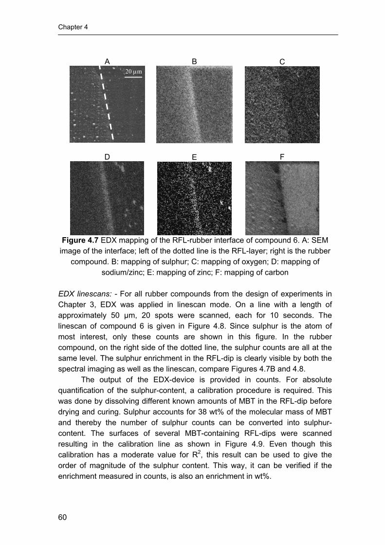
Chapter 4
A
20 μm
B
C
D
E
F
Figure 4.7 EDX mapping of the RFL-rubber interface of compound 6. A: SEM
image of the interface; left of the dotted line is the RFL-layer; right is the rubber compound. B: mapping of sulphur; C: mapping of oxygen; D: mapping of
sodium/zinc; E: mapping of zinc; F: mapping of carbon EDX linescans: - For all rubber compounds from the design of experiments in Chapter 3, EDX was applied in linescan mode. On a line with a length of approximately 50 µm, 20 spots were scanned, each for 10 seconds. The linescan of compound 6 is given in Figure 4.8. Since sulphur is the atom of most interest, only these counts are shown in this figure. In the rubber compound, on the right side of the dotted line, the sulphur counts are all at the same level. The sulphur enrichment in the RFL-dip is clearly visible by both the spectral imaging as well as the linescan, compare Figures 4.7B and 4.8.
The output of the EDX-device is provided in counts. For absolute quantification of the sulphur-content, a calibration procedure is required. This was done by dissolving different known amounts of MBT in the RFL-dip before drying and curing. Sulphur accounts for 38 wt% of the molecular mass of MBT and thereby the number of sulphur counts can be converted into sulphur-content. The surfaces of several MBT-containing RFL-dips were scanned resulting in the calibration line as shown in Figure 4.9. Even though this calibration has a moderate value for R2, this result can be used to give the order of magnitude of the sulphur content. This way, it can be verified if the enrichment measured in counts, is also an enrichment in wt%.
60

Curative migration from rubber into the RFL dip film
The sulphur levels at the interface in the dip and at 5, 10 and 15 µm from the interface in the dip were measured. An enrichment of curatives in the dip near the interface takes place for all compounds. The degree of enrichment varies between the various compounds.
Figure 4.8 EDX-linescan for sulphur of the RFL-rubber interface for compound
6
Figure 4.9 EDX-calibration for the RFL-dip for the atomic sulphur content
Since linescans were performed on all the compounds of the
experimental design of Chapter 3, the same statistical tools can be used to investigate the influence of each separate curative on the migration behaviour, independently. A total of 4 models was created: a model for the atomic sulphur content directly at the interface (1), and at various distances from the interface in the RFL-dip layer, being: 5 μm (2), 10 μm (3) and 15 μm (4). Just as in Chapter 3, the accuracy and the predictive power of the models were
61

Chapter 4
determined by the R2, R2adj and the Q2. Figure 4.10 gives these parameters and
the observed versus calculated plots. From this figure it can be concluded that all models have a good fit and predictive power, because Q2 is higher than 0.5 for all models. The model for the atomic sulphur content at 15 μm from the RFL-rubber interface resulted even in an excellent model, judged from the Q2 that is higher than 0.9, Figure 4.10D.
No models could be created from the sulphur counts on the rubber side, because the yield of counts was too low. The atomic sulphur content in the rubber varied between 0.5 and 2.4 wt%, calculated from the minimum and maximum amount of curatives that were mixed in the rubber compound according to the experimental design. The atomic sulphur content in the dip varied between 1 to 14 wt%, resulting into a much better discrimination.
A
B
C D
Figure 4.10 Observed versus calculated responses of the atomic sulphur
content measured by SEM-EDX; A: directly at the interface; B: in the RFL-dip, 5 μm from the RFL-rubber interface; C: in the RFL-dip, 10 μm from the RFL-rubber interface; D: in the RFL-dip, 15 μm from the RFL-rubber interface
62

Curative migration from rubber into the RFL dip film
The models allowed to calculate the contribution of each separate curative component on the total atomic sulphur content in the RFL-dip at various distances from the RFL-rubber interface. In this way the migration patterns could be reconstructed. Figure 4.11 shows the calculated concentration patterns for insoluble sulphur (OT 20) in the RFL-layer for two concentrations of OT20 mixed in the rubber compound. One compound contained 1 phr of OT20, the other 4 phr. The levels of MBTS and TBBS were kept at 0.5 and 1 phr, respectively, for both compounds. Increasing the amount of insoluble sulphur in the rubber compound increases the absolute level of the atomic sulphur content in the RFL-dip layer; the pattern of decreasing concentration as a function of the distance from the RFL-rubber interface remains the same. The calculated H-pullout force, using the models from Chapter 3, for the compound with 1 phr of insoluble sulphur is 81 N. That for the compound with 4 phr results in a H-pullout force of 79 N. There is practically no influence of the amount of insoluble sulphur on the adhesion.
Figure 4.11 Influence of the amount of OT20 on the calculated linescans for
atomic sulphur; MBTS = 0.5 phr, TBBS = 1 phr
Figure 4.12 shows the calculated concentration patterns for low and high loadings of MBTS, for the OT20 and TBBS concentrations at their centre values. The compound containing a low amount of MBTS results in a much lower atomic sulphur content at the RFL-rubber interface than the compound with a high amount of MBTS. Furthermore, the migration pattern of the compound with low MBTS content is less steep than that of the compound with high MBTS content. The corresponding H-pullout forces for the compounds with low and high MBTS content are 89 N and 72 N respectively. An increase in the amount of MBTS results in a decrease in adhesion, as already discussed in Chapter 3.
63

Chapter 4
Figure 4.12 Influence of the amount of MBTS on the calculated linescans for
atomic sulphur; OT20 = 2.5 phr, TBBS = 1 phr Figure 4.13 shows the calculated migration patterns for compounds with
low and high amounts of TBBS, keeping the OT20 and MBTS concentrations at their centre values. Just like for MBTS, decreasing the amount of TBBS results in a decrease in atomic sulphur level at the RFL-rubber interface and decreases the steepness of the migration pattern as well. The linescan of the compound with high TBBS loading even results in a lower concentration of atomic sulphur far from the RFL-rubber interface than that of the compound without TBBS. This is most probably due to the high concentration of atomic sulphur at the RFL-rubber interface, blocking the migration of sulphur and MBTS. The corresponding H-pullout values for the compound containing no TBBS is 119 N, that of the compound containing 2 phr of TBBS is 75 N. These values are calculated using the model from Chapter 3.
Figure 4.13 Influence of the amount of TBBS on the calculated linescans for
atomic sulphur; OT20 = 2.5 phr, MBTS = 0.5 phr
64

Curative migration from rubber into the RFL dip film
4.3.2 Raman Spectroscopy
Figure 4.14 shows the Raman spectra of the two accelerators, MBTS and TBBS. MBT is also shown in this figure, because this is the vulcanisation reaction product of both accelerators. In Figure 4.14, the spectra are shifted arbitrarily along the vertical axis. Just as reported in literature6-9, the peaks in the resulted spectra are very clear and the reaction product MBT has some unique peaks compared to MBTS and TBBS.
Figure 4.14 Raman spectra of MBTS and TBBS and their reaction product
MBT Figure 4.15 shows the spectra of the two uncured components of the RFL-dip: the resin (A) and the latex (B). The spectrum of the RF resin does not show any distinctive peaks, but it shows a shoulder at approximately 500 cm-1. The spectrum of the latex shows clear peaks at shifts of approximately 1700, 1400, 1300 and 1000 cm-1. The spectrum of the combined uncured RFL-dip is shown in Figure 4.16A. This spectrum shows a strong resemblance with the spectrum of the latex, because of its distinctive peaks. Next to these peaks, the shoulder of the resin at 500 cm-1 can also be observed. Figure 4.16B shows the spectrum of the cured RFL. Unfortunately, this spectrum does not show the latex peaks nor the resin shoulder clearly anymore. Additional experiments with RFL-rubber composites, which were prepared in a way similar to the SEM-EDX measurements, failed. Samples were prepared with uncured and cured RFL-dip layers. To clarify why also the measurements with the uncured RFL failed, the uncured latex and resin were separately kept in an oven at vulcanisation temperature, 150°C, for about 15 minutes. The exposure to this temperature made the RF resin dark, because of which the absorption of laser light increased to such an extent that a hole in the surface was burned. Furthermore, the latex component showed so much
65

Chapter 4
fluorescence, that the Raman signal could not be detected anymore. These experiments were therefore not further pursued.
A B
Figure 4.15 Raman spectra of A: dried uncured RF resin; and B: dried uncured latex
A B
Figure 4.16 Raman spectra of A: dried uncured RFL-dip; and B: cured RFL-dip 4.3.3 Nano-indentation
An example of a deflection-indentation curve is shown in Figure 4.17. A linescan was obtained using the method of Tsukruk.12 For calculation of the modulus, the slope of the initial part of the retreating curve is used. This part is indicated in Figure 4.17 with an arrow. In order to calculate the modulus, the value for this slope is used as input to equation 4.1.13 For every 1.5 µm along the linescan through the RFL-rubber interface, a modulus was determined 49 times on the 500 by 500 nm area resulting in a histogram of values obtained. Figure 4.18A shows the modulus histogram of the interface itself, Figure 4.18B shows that of the RFL-dip 14 μm from the interface. It is clear that the interface has a higher modulus than the RFL-dip 14 μm from the interface. However, the
66

Curative migration from rubber into the RFL dip film
histogram at the interface shows a broader distribution in the values for the modulus.
The full linescan of the nano-indentation of the centre compound is shown in Figure 4.19. Following Figure 4.18, the modulus of the RFL-dip increases when approaching the RFL-rubber interface and the spread of the value for modulus increases as well. On the rubber side, there is some increase in modulus at the scan distance of around 10 μm. This is most likely due to the fact that the rubber compound is not a homogeneous polymer substance, but contains large amounts of hard additives such as carbon black. With these values neglected, the rubber modulus is approximately 15 MPa. However, the Young’s modulus measured in Chapter 3 for this compound is 4 times lower: 3.7 MPa. The high values for modulus resulting from the nano-indentation experiments are most probably due to the many assumptions used in equation 4.1, such as spring constant, contact area and Poisson ratio, in combination with the heterogeneous nature of the carbon black reinforced rubber.
Figure 4.17 Example of a deflection-indentation curve
( )Adh
dPE 12
1 2 πυ−= (eq. 4.1)
Where: E = Young’s modulus [Pa] υ = Poisson ratio, assumed value: 0.5 [-]
dhdP
= initial slope of the retreating curve: load/indentation [N/m]
A = estimated contact area [m2]
67

Chapter 4
A B
Figure 4.18 Modulus histograms of A: the RFL-dip directly at the RFL-rubber interface; B: at 14 μm from the interface
Comparing the nano-indentation linescan, Figure 4.19, with that of the
SEM-EDX scan for sulphur and zinc/sodium for the same centre compound 6 in Figure 4.20, there is a close resemblance. In the first five micrometers into the RFL from the RFL-rubber interface, there is quite a significant drop in modulus, atomic sulphur and zinc/sodium. This correlation indicates that the high atomic sulphur and zinc contents account for the vulcanisation of the latex-component in the RFL. The local crosslink density of the RFL is high at the RFL-rubber interface and decreases with further distance from this interface. An important observation is that a high amount of sulphur and zinc in the RFL-dip apparently can be translated into a high local crosslink density.
Figure 4.19 Nano-indentation linescan of a RFL-rubber interface for the centre
compound of Chapter 3
68

Curative migration from rubber into the RFL dip film
Figure 4.20 SEM-EDX linescan of a RFL-rubber interface for the centre
compound of Chapter 3 4.4 DISCUSSION 4.4.1 Shape of the penetration curves of curatives in the RFL-layer
From all SEM-EDX experiments, mapping, spectral imaging and linescan, it can be concluded that an enrichment of atomic sulphur takes place in the RFL-layer near the RFL-rubber interface. To have an idea of the order of magnitude of the contribution of each curative to this enrichment, on all compounds of the experimental design of Chapter 3 linescans were performed.
In Figure 4.12, the addition of 1 phr of MBTS (0.6 wt% of the whole compound) increased the atomic sulphur content in the RFL near the RFL-rubber interface from 6.3 wt% to 10.6 wt%: an increase of 4.3 wt%. The chemical structure of MBTS consists for 38.6 wt% out of sulphur atoms. This corresponds to an apparent concentration of MBTS in the RFL near the RFL-rubber interface of approximately 11 wt%. A similar calculation for TBBS results in a concentration near the RFL-rubber interface of 9.7 wt%, for the initial concentration in the rubber compound of 1.2 wt%. The concentration of sulphur, polymeric sulphur or the S8 molecule, is 3.1 wt% near the RFL-rubber interface for 1.9 wt% mixed into the rubber compound.
These calculations demonstrate that the RFL-dip has a strong affinity for especially the accelerator moieties that were mixed into the rubber compound. The high concentration of accelerators increases the crosslink density of the RFL near the RFL-rubber interface, as verified by the nano-indentation experiments. This high local crosslink density near the interface hampers further migration of curatives into the dip as it is well known that high crosslink densities decrease the mobility of low molecular weight or gaseous compounds in rubber. Furthermore, the crosslinks themselves consist out of sulphur atoms.
69

Chapter 4
These are fixed and cannot migrate further. These two mechanisms result in a steep penetration pattern rather than a flat one. Increasing the amount of accelerators in the rubber compound thereby increases the steepness of the penetration patterns of atomic sulphur into the RFL-dip. 4.4.2 Correlation with rubber-cord adhesion measurements
In Chapter 3, it was concluded that increasing the amount of accelerators mixed into the rubber compound decreased the adhesion to a large extent of RFL-treated cords to rubber. The influence of the amount of insoluble sulphur was least significant, as illustrated in Figure 4.21.
From the SEM-EDX measurements, it can now be concluded that the RFL-dip has a very high affinity for especially the accelerator molecules mixed into the rubber compound, and this results in an enrichment in the RFL near the RFL-rubber interface. The insoluble sulphur mixed in the rubber compound does not affect the degree of enrichment to a large extent. There is an inverse correlation between the adhesion and the atomic sulphur level in the RFL near the RFL-rubber interface composed of sulphur composed of sulphur in the accelerators and atomic sulphur. This provides convincing evidence that enrichment of curatives plays a predominant role in the mechanism of RFL to rubber adhesion.
Figure 4.21 The influence of the amount of curatives in the rubber compound
on the H-pullout adhesion
In the following chapters, extensive investigations into both the atomic sulphur content in the RFL-dip and the adhesion of RFL-treated cords to rubber compounds will be reported, in order to derive a mechanism that explains the behaviour of the rubber curatives on the adhesion.
70

Curative migration from rubber into the RFL dip film
4.5 CONCLUSIONS SEM-EDX is a powerful analytical tool for analysing curative distribution
in the RFL-rubber interface. It showed an enrichment of rubber curatives in the RFL-layer close to the RFL-rubber interface; the amount of atomic sulphur in the RFL-layer detected by EDX is at such high level that discriminating experiments could be performed. Nano-indentation experiments demonstrated that the high atomic sulphur content in the RFL, near the RFL-rubber interface, results in a high modulus corresponding to a high local crosslink density. Unfortunately, many assumptions had to be made to calculate absolute moduli from these data. This resulted in values for the modulus of the rubber compound that were approximately 4 times higher than the modulus obtained from macroscopic tensile tests. A third analytical technique, Raman spectroscopy, turned out not to be useful to analyse the RFL-rubber interface.
The RFL-dip has a high affinity towards the accelerator molecules and a moderate affinity towards polymeric or cyclic sulphur molecules. As already known from Chapter 3, also the adhesion is influenced to a large extent by the accelerator components and to a lesser extent by the amount of insoluble sulphur mixed into the rubber compound. There is an inverse correlation between the atomic sulphur content in the RFL-layer near the RFL-rubber interface and the adhesion. 4.6 REFERENCES 1. D.B. Wootton, "The Application of Textiles in Rubber". 2001, Shawbury:
Rapra technology LTD. 2. W. Weening and W.H. Hupje, Kautsch. Gummi Kunstst., 25, 321-324
(1972). 3. A.G. Causa, "Tire Reinforcement and Tire Performance", ASTM STP
694, 200- 238 (1979). 4. B.C. Begnoche and R.L. Keefe, Rubber Chem. Technol., 60, 689 (1987). 5. G. Gillberg and L.C. Sawyer, J. Appl. Polym. Sci., 28, 3723-3743 (1983). 6. M.M. Coleman, J.R. Shelton, and J.L. Koenig, Rubber Chem. Technol.,
45, 173 (1972). 7. J.R. Shelton, J.L. Koenig, and M.M. Coleman, Rubber Chem. Technol.,
44, 904 (1971). 8. J.L. Koenig, M.M. Coleman, and J.R. Shelton, Rubber Chem. Technol.,
44, 71 (1971). 9. R.S. Kapur, J.L. Koenig, and J.R. Shelton, Rubber Chem. Technol., 47,
911 (1974). 10. C.A. Stevens, in "Polymer Bonding conference", 2004. Munich.
71

Chapter 4
11. R. Jenkins, "An introduction to X-ray spectrometry". 1974, New York: Heyden & Son Ltd. p. 163.
12. V.V. Tsukruk, Z. Huang, S.A. Chizhik, and V.V. Gorbunov, J. Mater. Sci., 33, 4905-4909 (1998).
13. I.N. Sneddon, Int. J. Eng. Sci., 3, 47-57 (1965).
72

Chapter 5
Investigations into the migration pattern of curatives, in relation to the adhesion between RFL-treated cords and rubber
compounds
Three approaches to alter the atomic sulphur pattern in the RFL-dip are described. The goal is to obtain information on the relation between this pattern and the adhesion between RFL and rubber. Another goal is to clarify what causes the atomic sulphur enrichment at the RFL-rubber interface and the steep decrease into the dip. It is found that the enriching species that migrate from rubber into the dip is, most likely, formed somewhere in time during the vulcanisation reaction. Furthermore, the latex phase of the RFL-dip is responsible for the enrichment and the shape of the migration pattern. The RF resin of the RFL-dip merely dilutes the latex. The RFL appears to be saturated with accelerator already at low DCBS loadings present in the rubber, due to the high molar mass of DCBS. Increasing the DCBS content in the rubber does not have a significant influence neither on the atomic sulphur content in the RFL-dip nor on the H-pullout force.

Chapter 5
5.1 INTRODUCTION
Although the RFL-treatment of textile cords is a mature technique, invented in 19381, the precise mechanism by which adhesion to rubber is obtained remains unclear and the level of understanding is still rather pragmatic.2-7 In Chapter 3, it was concluded that there is a correlation between the t90 of the rubber compound and the measured (H-pullout) adhesion. This is in agreement with work published earlier by several researchers.8-10 In Chapter 4, SEM-EDX turned out to be a useful technique to analyse the RFL-rubber interface.11, 12 It was concluded that there is a strong enrichment of atomic sulphur in the RFL-layer near the RFL-rubber interface. It was also concluded that especially the accelerator molecules are the cause of this enrichment. In the present chapter, attempts are described to influence the shape of the sulphur migration pattern and to study the effect on adhesion to rubber. The methods used to influence the migration pattern are:
• Pre-pressing the fibre-rubber composite at 100°C for 20 minutes. The basic idea is, that during the pre-pressing period migration can take place and an equilibrium can be reached. After the pre-pressing period, vulcanisation is carried out at 150°C.
• Studying the migration behaviour in dried latex. Dried latex can be regarded as RFL without RF resin. By studying the sulphur migration curves through the latex-rubber interface, it can be investigated whether the RF resin is the cause for the steep sulphur pattern observed by a blocking effect, or that it results from a competition between diffusion and reaction of the migrating species.
• Studying accelerator molecules with different reaction and diffusion properties. DCBS is an accelerator with a high molecular weight of 347 g/mol. The results for this accelerator are compared to those for TBBS from Chapters 3 and 4. To make sure that the difference in results originate from the size of the molecule rather than from the type of amine that is formed, measurements are also performed with CBS. CBS and TBBS have a similar molecular weight, 264 and 238 g/mol, respectively. DCBS and CBS are investigated by the method of design of experiments.
5.2 EXPERIMENTAL 5.2.1 Materials
All experimental work was performed on a model carcass masterbatch, as given in Table 5.1. For simplicity reasons, only NR was used instead of a NR/SBR blend. Crystex OT20, CBS, DCBS and PVI (all ex. Flexsys) were used as curatives. The type of latex used for the RFL-dip was styrene-butadiene-2-
74

Migration pattern of curatives in relation to the adhesion
vinylpyridine terpolymer latex obtained from Eliokem (Pliocord 106s). Poly-p-phenylene terephthalamide fibres were obtained from Teijin Twaron. The type of aramid used in this investigation was Twaron 1008. The linear density was 1680 dtex (168 g per 1000 m) with a degree of twisting of 330/330 twists per meter. The aramid fibre had a water-based spin finish without adhesion activating additives. Table 5.1 Composition of the model carcass Masterbatch13 Component Amount (phr) NR SIR CV 60 100 Carbon black (Statex N-660) 40 ZnO (Silox 3c) 3 Stearic acid 2 Hydrogenated aromatic oil (Nytex 840) 13
TMQ (Flectol H) 0.5 6 PPD (Santoflex 13) 1 Octyl-phenol formaldehyde resin (Ribetak 7510) 4
5.2.2 Rubber compounds
A total of 180 kg of masterbatch was mixed in a Werner en Pfleiderer GK 270N tangential internal mixer. The curatives were added to the rubber compounds on a 2-roll mill. For the pre-pressing experiments and the experiments with bare latex instead of RFL, compounds 2, 8, 10 and 12 of the design from Chapter 3 were used. These compounds are listed in Table 5.2. Table 5.2 Composition and adhesion measurements of the used compounds Compound S (phr) MBTS (phr) TBBS (phr) H-pullout force (N) SPAF (N) 2 4 0 1 98.5 143.1 8 4 0.5 2 69.1 39 10 2.5 1 0 103.7 190.1 12 2.5 1 2 78.7 51.2
To study the effect of CBS and DCBS, a Design Of Experiments (DOE) was used. In all compounds insoluble sulphur, OT20, and PVI were used as crosslinking agent and retarder, respectively. The accelerator was changed: CBS for design A and DCBS for design B. Both designs contained variations in the amounts of sulphur and accelerator and were composed according to the Central Composite Face (CCF) design, resulting in 11 compounds, as shown in Table 5.3. MODDE 6.0 software from Umetrics was used to model the properties within the limits of the amounts of curatives added. Table 5.3 shows the amounts in phr. Converting phr in mmol, the lower limit of both designs was 2.1 mmol per 100 g of rubber, and the upper limit 6.3 mmol. These limits are within the range of the amounts of TBBS from the design of Chapter 3, making a comparison possible.
75

Chapter 5
Table 5.3 Compositions of the rubber compounds of Design A and B Design S (phr) CBS (phr) DCBS (phr) PVI (phr) A1 1 0.56 - 0.1 A2 4 0.56 - 0.1 A3 1 1.67 - 0.1 A4 4 1.67 - 0.1 A5 1 1.11 - 0.1 A6 4 1.11 - 0.1 A7 2.5 0.56 - 0.1 A8 2.5 1.67 - 0.1 A9 2.5 1.11 - 0.1 A10 2.5 1.11 - 0.1 A11 2.5 1.11 - 0.1 B1 1 - 0.73 0.1 B2 4 - 0.73 0.1 B3 1 - 2.18 0.1 B4 4 - 2.18 0.1 B5 1 - 1.46 0.1 B6 4 - 1.46 0.1 B7 2.5 - 0.73 0.1 B8 2.5 - 2.18 0.1 B9 2.5 - 1.46 0.1 B10 2.5 - 1.46 0.1 B11 2.5 - 1.46 0.1 5.2.3 Compound characterisation
The cure characteristics of the compounds were measured with a RPA 2000 dynamic mechanical curemeter of Alpha Technologies. The cure curves were recorded at 150ºC, with a frequency of 0.833 Hz and 0.2 degrees strain. The responses used for the experimental designs were the scorch time t2, the optimum cure time t90 and the maximum torque S’
max. The RPA 2000 was also used to investigate the influence of the pre-pressing time of the four compounds from the design of Chapter 3. 5.2.4 Fibre treatment
The p-aramid fibres were dipped twice: initially with an epoxy predip, followed by a RFL-dip. The composition of the epoxy predip solution is depicted in Table 5.4; the solid content was 2 wt%. The preparation of the RFL-dip took place in two stages. First, a resorcinol formaldehyde resin solution was made and matured for 5 hours at 25°C. Second, latex and more water were added to obtain a RFL-dip with a solid content of 17 wt%. The compositions of the resin solution and of the final RFL-dip are shown in Table 5.4.
The cord was pretreated by passing it through the predip-container and through two ovens: the first with a temperature of 150°C, the second 240°C. Residence times were 120 and 90 seconds, respectively. Subsequently, the cord was passed through the RFL-dip container. The RFL-layer on the cord
76

Migration pattern of curatives in relation to the adhesion
was cured in a third oven at 235°C for 90 seconds. In every oven a tensile force of 8.5 N was applied to the cord.
Table 5.4 Composition of the epoxy predip and the RFL-dip Component Amount (g) Solid (g) Epoxy predip
Water 978.2 - Piperazine 0.50 0.50
Aerosol OT (75%) 1.3 0.98 GE-100 epoxide 20.0 20.0
Total 1000 21.48 Resin solution
Water 4305 - NaOH (5%) 239.9 12.0 Resorcinol 181.3 181.3
Formaldehyde (37%) 274.3 101.49 Total 5000.5 294.8
RFL-dip Water 466.9 - Latex 908.4 363.4
Resin solution 1124.7 66.31 Total 2500 429.7
5.2.5 Adhesion testing
The adhesion between dipped cord and rubber compound after curing was measured by H-pullout measurements as described in ASTM D4776-98. The vulcanisation time for this experiment was adjusted to t90 plus 9 minutes because of the thick rubber samples employed. The maximum force recorded during the pullout test is referred to as pullout force. Each H-pullout value is the average of 40 measurements. 5.2.6 SEM-EDX measurements
The SEM-EDX equipment used was a LEO 1550 FEG/Thermo Noran Instruments, model Vantage. The accelerating voltage was 15 kV and the sample distance was 9 mm. As only the interface RFL-rubber is of interest in the present context, for ease of preparation, the RFL was supported and cured on to aluminium foil instead of on the cord and subsequently co-vulcanised to the rubber compound using a compression set mould. The sample was pressed at a temperature of 150°C at a time of t90 plus 9 minutes. Sample preparation is described in more detail in Chapter 4.
5.3 RESULTS AND DISCUSSION
For both the pre-pressing experiments and the experiments with bare latex, compounds 2, 8, 10 and 12 from the design in Chapter 3 were used. These compounds were chosen because compounds 2 and 10 showed relatively high adhesion compared to compounds 8 and 12: Table 5.2.
77

Chapter 5
Furthermore, compounds 2 and 10 showed a relatively shallow migration curves with a low atomic sulphur content near the RFL-rubber interface: Figure 5.1.
Figure 5.1 SEM-EDX linescans for compounds 2, 8, 10 and 12 5.3.1 Pre-pressing Cure characteristics: - The basic idea of pre-pressing the fibre-rubber composites was, that at 100°C diffusion can take place, but no vulcanisation yet. To verify that there was no vulcanisation at 100°C, compounds 02, 08, 10 and 12 from the design of Chapter 3 were investigated with the RPA 2000. The temperature applied in the RPA 2000 was 100°C for 20 minutes, followed by 150°C for 30 minutes. For all four compounds, there was no increase in torque during the 20 minutes at 100°C. The rheograms for the pre-heated as well as for the virgin compounds at 150°C are shown in Figure 5.2. For all compounds, the initial torque for the pre-heated compounds is still the same as the initial torque for the not pre-heated compounds. This indicates that during the pre-heating period no vulcanisation has taken place. As expected, the scorch time for the pre-heated samples is shorter than for the original compounds.
78

Migration pattern of curatives in relation to the adhesion
A B
C D
Figure 5.2 Rheometer curves of the compounds with and without pre-heating for 20 minutes at 100°C; A: compound 02; B: compound 08; C: compound 10;
D: compound 12 Preparation of the samples: - The H-pullout samples that were not pre-pressed were prepared as described in ASTM D 4776-98 and the SEM-EDX samples as described in section 4.2.2. The pre-pressed samples, both H-pullout and SEM-EDX, were prepared in a similar manner with one extra pressing step. Before pressing the samples in a press at 150°C, they were pressed at 100°C for 20 minutes. After this pre-pressing step, the samples were put in a press that had already a temperature of 150°C. In the second pressing step final vulcanisation took place for a period of time of t90 plus 9 minutes. SEM-EDX: - Linescans were performed on a total of 8 cured RFL-rubber interfaces: on the four samples without the pre-pressing treatment, and on the four samples after being pre-pressed and cured. These linescans are shown in Figure 5.3. Compound 02, Figure 5.3A, shows an increase in atomic sulphur
79

Chapter 5
level on both the rubber and the dip side. The difference in atomic sulphur level in the RFL near the interface is around 200 counts. This may be because of an actual increase in migration of the curatives. However, the other three compounds, Figure 5.3B, C and D, do not show any significant difference with their not pre-pressed counterparts.
A
B
C
D
Figure 5.3 SEM-EDX sulphur linescans of the compounds with and without
pre-pressing to RFL-dip; A: compound 02; B: compound 08; C: compound 10; D: compound 12
H-pullout tests: - The H-pullout results are shown in Figure 5.4. Pre-pressing the rubber compounds to the RFL-treated cords before cure increases the adhesion from approximately 100 N to 120 N for compound 02. This is a significant increase, taking the standard deviation into account. However, pre-pressing compounds 08, 10 and 12 to RFL-treated cords does not result in significantly different H-pullout forces. This corresponds to the SEM-EDX measurements where the linescans of compound 02 are different, and those of compounds 08, 10 and 12 are not.
80

Migration pattern of curatives in relation to the adhesion
0
20
40
60
80
100
120
140
compound 2 compound 8 compound 10 compound 12
H-p
ullo
ut fo
rce
(N)
no pre-pressing
pre-pressed compounds
Figure 5.4 H-pullout results for the four compounds with and without the pre-
pressing treatment 5.3.2 Experiments without RF resin
To determine what causes the enrichment and the migration pattern of the curatives in the RFL-dip, experiments were carried out with both RFL and bare latex. The bare latex can be considered as RFL without the RF resin. Two possible explanations for the steep pattern of atomic sulphur in the RFL-dip could be: (1) blocking of the migrating curatives by the RF resin, and (2) a competition between diffusion through and reaction between the latex phase of the RFL-dip and the curatives.
Both the RFL and the latex layers were prepared by the method described in Chapter 4. They were put in an oven at 235°C for 90 seconds after the unforced drying on aluminium foil, in order to make a fair comparison.
In Figure 5.5, the SEM-EDX linescans are shown for all four rubber compounds. The steepness of the migration curves in the dip-layer does not differ significantly between bare latex and RFL-dip. Therefore, it can be concluded that the resin does not hamper the diffusion of the curatives in the dip layer to a large extent. Most likely, the steep pattern of atomic sulphur in the dip is caused by a competition between a reaction and diffusion of the curatives.
There is no significant difference for compound 10 between the linescans of the latex and RFL: Figure 5.5C. However, for the other compounds, Figure 5.5A, 5.5B, and 5.5D, the sulphur counts on the dip side are at a higher level for bare latex than for RFL. The explanation can be, that the curatives are only soluble in the latex phase and not in the RF resin phase, because the RF resin in the RFL acts as an inactive filler when considering the migration. In other words, the RF resin dilutes the latex, thereby decreasing the sulphur counts in the dip but keeping the slope of the pattern the same.
81

Chapter 5
A
B
C
D
Figure 5.5 SEM-EDX sulphur linescans of the interface between rubber
compounds and both RFL-dip and bare latex; A: compound 02; B: compound 08; C: compound 10; D: compound 12
5.3.3 Variation in type of accelerators
In the following section, compounds containing DCBS as accelerator are investigated. DCBS is a high molecular weight accelerator, 347 g/mol, which could cause a slow diffusion into the RFL-layer. Furthermore, it is commonly known that this accelerator results in a slow vulcanisation of rubber compared to TBBS. This difference in both diffusion and reaction rate, could provide more insight into the effect of the penetration curve of curatives into the RFL-dip on the adhesion. Therefore, both H-pullout and SEM-EDX measurements were performed according to a Design of Experiments.
The same design, CCF, was applied to another accelerator CBS that has a similar molecular weight as TBBS but a different amine: cyclohexylamine, released during vulcanisation. This amine is comparable to the amine released by DCBS which is di-cyclohexylamine. In this way, it may be verified if the difference between DCBS and TBBS is due to their molecular weight or to their different chemical structure.
82

Migration pattern of curatives in relation to the adhesion
The experimental results for the RPA 2000 and H-pullout measurements based on the design of Table 5.3 are shown in Tables 5.5 and 5.6 for CBS and DCBS, respectively. These results were analysed using DOE-software, to investigate the influence of each curative independently. Table 5.5 Experimental results for design A with CBS as accelerator Compound S (phr) CBS
(phr) t2 (min) t90
(min) max S' (dNm)
H-force (N)
standard deviation H-force
A1 1 0.56 0.5 22.5 1.0 67.5 5.9 A2 4 0.56 1.6 14.0 3.5 119.1 9.6 A3 1 1.67 2.2 11.9 3.0 78.8 12.5 A4 4 1.67 2.6 8.9 5.6 78.3 7.3 A5 1 1.11 0.9 12.2 2.5 83.3 10.6 A6 4 1.11 1.9 10.6 4.9 83.2 7.3 A7 2.5 0.56 1.1 14.2 2.9 108.1 10.4 A8 2.5 1.67 2.3 9.0 4.7 79.6 8.4 A9 2.5 1.11 1.7 10.5 4.1 81.7 7.9 A10 2.5 1.11 1.6 10.4 4.1 75.4 9.1 A11 2.5 1.11 1.8 10.6 4.1 79.4 6.4
Table 5.6 Experimental results for design B with DCBS as accelerator Compound S (phr) DCBS
(phr) t2 (min) t90
(min) max S' (dNm)
H-force (N)
standard deviation H-force
B1 1 0.73 0.7 22.5 1.5 74.7 9.4 B2 4 0.73 1.8 20.5 3.4 119.7 16.4 B3 1 2.18 2.5 17.8 2.8 67.9 6.3 B4 4 2.18 1.7 14.3 5.0 105.4 10.4 B5 1 1.46 1.1 18.4 2.3 73.4 9.3 B6 4 1.46 1.9 16.4 4.5 124.3 13.3 B7 2.5 0.73 1.1 20.5 2.9 100.7 13.1 B8 2.5 2.18 1.8 14.5 4.1 88.2 6.8 B9 2.5 1.46 1.9 16.2 3.6 96.5 7.2 B10 2.5 1.46 1.6 16.1 3.7 95.4 7.6 B11 2.5 1.46 1.4 16.1 3.7 96.8 6.1
Evaluating the designs: - Just like in Chapter 3, section 3.3.1, the accuracy and the predictive power of the models are determined by the R2, R2
adj and the Q2. The observed versus calculated plots are shown in Figures 5.6-5.11. All obtained models resulted in a Q2 higher than 0.5, indicating that the predictive power of all models is good. The design for the scorch time of DCBS, Figure 5.9A, resulted in the lowest value of Q2: 0.518. This is just above the minimum value of 0.5, above which the predictive power of the model can still be called good. Compound A1 was not included in the model calculations, because this compound showed rubber bulk tear instead of interfacial failure. Furthermore, just as the model for the t90 from Chapter 3, the model for the t90 for Design A needed a logarithmic transformation, in order to get a good fit. For Design B, with DCBS as accelerator, none of the models needed any transformation.
83
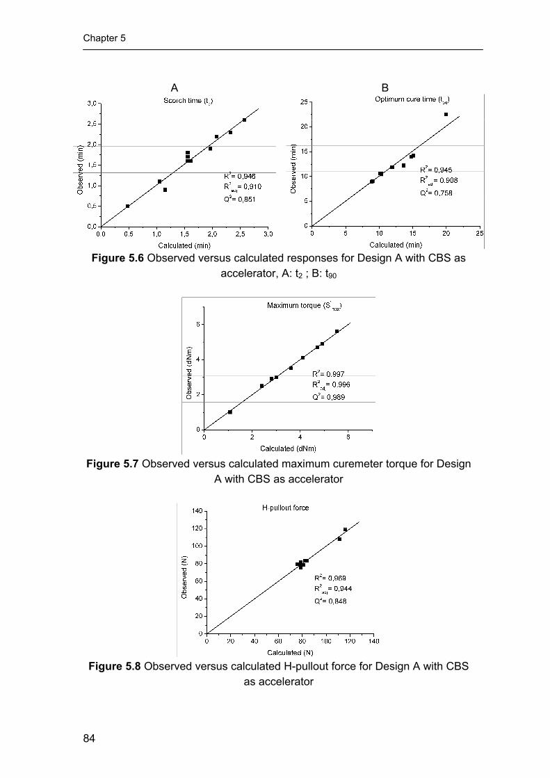
Chapter 5
A B
Figure 5.6 Observed versus calculated responses for Design A with CBS as accelerator, A: t2 ; B: t90
Figure 5.7 Observed versus calculated maximum curemeter torque for Design
A with CBS as accelerator
Figure 5.8 Observed versus calculated H-pullout force for Design A with CBS
as accelerator
84

Migration pattern of curatives in relation to the adhesion
A B
Figure 5.9 Observed versus calculated responses for Design B with DCBS as accelerator, A: t2 ; B: t90
Figure 5.10 Observed versus calculated maximum curemeter torque for Design
B with DCBS as accelerator
Figure 5.11 Observed versus calculated H-pullout force for Design B with
DCBS as accelerator
85

Chapter 5
5.3.4 Evaluation of the individual influences of various curatives on responses
Influence of curatives on responses: - In Figures 5.12-5.14 the influence of curatives on the cure characteristics is shown, as derived from the various models. In these figures, the accelerators TBBS and MBTS are also shown, as based on the models from Chapter 3, even though MBTS is not of the sulphenamide type. The amounts of accelerators, on the horizontal axes of these figures, are expressed in mmol/100 g of rubber in order to make a fair comparison. For all these figures, the insoluble sulphur level was kept constant at 2.5 phr, the centre value for all designs. Figure 5.12 shows the influence of the different accelerators on scorch time. The three sulphenamide accelerators CBS, DCBS and TBBS are of the scorch delay type: increasing the amount of these accelerators increases the scorch time of the rubber compound for all three. In contrast, increasing the MBTS level decreases the scorch time, as might have been expected, because it is not a scorch delay type accelerator.
Figure 5.13 shows the influence of the accelerators on the optimum cure time t90. There is no significant difference in the developments of t90 when comparing CBS, TBBS and MBTS on a molar base. However, when DCBS is used as accelerator the level of the t90 is much higher. The overall value of t90, with DCBS as accelerator, is five minutes larger than for the other three accelerators. The maximum torque level, S’max, rises when more of each accelerator is added, Figure 5.14. The effect is least pronounced for MBTS.
Figure 5.12 Influence of the amounts of accelerators on t2 derived from the
Design of Experiments model
86

Migration pattern of curatives in relation to the adhesion
Figure 5.13 Influence of the amounts of accelerators on t90 derived from the
Design of Experiments model
Figure 5.14 Influence of the amounts of accelerators on S’max derived from the
Design of Experiments model
The influence of the type and amount of the accelerators on the H-pullout force is shown in Figure 5.15. It is evident from this figure that the H-pullout decreases in a systematic manner with increasing accelerator dosage. When comparing Figures 5.13 and 5.15, there is a correlation between the H-pullout force and the t90 of the rubber compounds for CBS, TBBS and MBTS used as accelerators. This was concluded already in Chapter 3. However, for DCBS this correlation does not fit anymore. The decrease in H-pullout force with increasing DCBS content is small compared to the other accelerators.
Figure 5.16 shows the influence of the amount of insoluble sulphur on the H-pullout force for the accelerators kept at their centre values: for CBS, DCBS and TBBS: 4.2 mmol/100 g; for MBTS 1.5 mmol/100 g of rubber. Increasing the amount of insoluble sulphur in the presence of CBS, TBBS and
87

Chapter 5
MBTS hardly affects the adhesion. However, in the presence of DCBS, the H-pullout force increases significantly.
From Figures 5.15 and 5.16, it can be concluded that DCBS shows quite a different behaviour from the other accelerators: the H-pullout force marginally decreases when increasing the amount of DCBS at constant sulphur level, and increases significantly when increasing the amount of insoluble sulphur at constant accelerator level. In order to explain this behaviour, SEM-EDX linescans were performed on all samples of Design B.
Figure 5.15 Influence of the amounts of accelerators on H-pullout force derived
from the Design of Experiments model
Figure 5.16 Influence of the amounts of insoluble sulphur on H-pullout force
derived from the Design of Experiments model SEM-EDX: - In Figure 5.17A, the linescans of compounds B7 and B8 are compared. The amount of insoluble sulphur was 2.5 phr for both B7 and B8, the
88

Migration pattern of curatives in relation to the adhesion
amounts of DCBS were 2.1 and 6.3 mmol/100 g of rubber, respectively. From this figure, it can be inferred that increasing the amount of DCBS does not affect the atomic sulphur level in the RFL-dip. Figure 5.17B shows the linescans of compounds B5 and B6, both compounds containing 4.2 mmol DCBS per 100 g of rubber. Compound B5 contains 1 phr of insoluble sulphur, compound B6 4 phr. It turns out that the atomic sulphur level in the RFL-dip (and in the rubber compound) increased significantly upon increase of the insoluble sulphur dosage. This behaviour is opposite to that of TBBS and MBTS, as seen in Chapter 4, where the amount of accelerator had a large effect, and the amount of insoluble sulphur a small one.
A B
Figure 5.17 SEM-EDX linescans; A: influence of the amount of DCBS; B: influence of the amount of insoluble sulphur
Subsequently, linescans were performed on all compounds from design
B, wherein DCBS was used as accelerator. Just as described in Chapter 4, the sulphur counts were transformed into sulphur wt% by calibration. The atomic sulphur level directly at the interface and 5, 10 and 15 µm from the interface were modelled, although only the atomic sulphur content at the RFL-rubber interface is of importance here. The observed versus predicted plot of the sulphur content is shown in Figure 5.18. The model resulted in a Q2 significantly larger than 0.5 and is therefore a model with good predictive power.
89

Chapter 5
Figure 5.18 Observed versus predicted plot of the atomic sulphur content
directly at the RFL-rubber interface for compounds of design B
As was described in Chapters 3 and 4, the cord-rubber adhesion largely depended on the amount of accelerator, when using MBTS and TBBS, and was hardly influenced by the amount of insoluble sulphur mixed into the rubber compound. The same was observed for the atomic sulphur content in the RFL at the RFL-rubber interface. In fact, an inverse correlation was obtained between adhesion and atomic sulphur content, when varying the amount of accelerator.
In Figure 5.19, the H-pullout force is now compared with the atomic sulphur content in the RFL at the RFL-rubber interface. The accelerator DCBS is compared with TBBS in this figure. Unlike TBBS, increasing the amount of DCBS in the rubber hardly affects neither the atomic sulphur content in the RFL-layer at the interface, nor the H-pullout force. Probably this behaviour is caused by the fact that, due to the high molecular weight of DCBS, the RFL is already saturated at the minimum value of the design: 2.1 mmol DCBS/100 g of rubber.
Figure 5.20 shows the H-pullout adhesion and the atomic sulphur level at the RFL-rubber interface with increasing insoluble sulphur level in the rubber compound, with both TBBS and DCBS at their centre values: 4.2 mmol/100 g of rubber. For the compound with DCBS as accelerator, the H-pullout increases significantly when the insoluble sulphur content is increased. When TBBS is used, there is only a small increase in H-pullout force found. The atomic sulphur level at the interface increases for both accelerators present.
This all leads now to the conclusion that an increase of atomic sulphur level in the RFL-dip at the RFL-rubber interface decreases the H-pullout force when caused by accelerators, however not by insoluble sulphur.
90

Migration pattern of curatives in relation to the adhesion
A B
Figure 5.19 A: H-pullout force versus the amount of accelerator; B: atomic sulphur content at the RFL-rubber interface versus amount of accelerator; the
insoluble sulphur content in the compound kept constant at 2.5 phr
A B
Figure 5.20 A: H-pullout force versus the amount of insoluble sulphur; B: atomic sulphur content at the RFL-rubber interface versus amount of insoluble
sulphur in the compound 5.4 CONCLUSIONS
Attempts were made to vary the migration pattern of curatives that can migrate from rubber into the RFL-dip. The approaches were: pre-pressing fibre-rubber composites, experiments with bare latex, and using accelerators with different reaction and diffusion speeds.
Pre-pressing the RFL-rubber interface before vulcanisation did not result in a different migration pattern. Also the H-pullout force hardly changed when fibre-rubber composites were pressed together for 20 minutes at 100°C prior to vulcanisation. Because pre-pressing had no effect, it is inferred that the
91

Chapter 5
migrating species are formed at some moment in time during the vulcanisation reaction. This will be investigated in more detail in Chapter 8.
The major conclusion from the experiments with the bare latex is that the latex part of the RFL is the cause for both the enrichment of curatives at the interface and the steep migration curve. The RF resin of the RFL-dip merely dilutes the latex but has no major effect on the development of the migration pattern. The influence of the type of latex will be described in more detail in Chapter 6.
Unlike for TBBS, the amount of high-molecular weight accelerator DCBS did not have a large influence on both adhesion and atomic sulphur level in the RFL-dip. Most likely, the RFL-dip layer becomes already saturated at the minimum value of 2.1 mmol/100 g of rubber for the experimental design used. On the other hand, the amount of insoluble sulphur appeared to have a positive influence on the H-pullout force for DCBS, where it had no significant influence when TBBS was used as accelerator. The combined results point to an overall negative influence of the atomic sulphur level at the RFL-rubber interface on the H-pullout force, when it comes from an accelerator. However, when it comes from insoluble sulphur, the influence is overall positive. The exact role of both sulphur and accelerator during vulcanisation in the adhesion mechanism will be further elucidated in Chapters 8 and 9. 5.5 REFERENCES 1. W.H. Charch, N.Y. Buffalo, and D.B. Maney, (US2128635) DuPont, 1938 2. N.K. Porter, J. Coat. Fabrics, 23, 34-45 (1993). 3. A.L. Miller and S.B. Robison, Rubber World, 137, 397 (1957). 4. R.V. Uzina, I.L. Schmurak, M.S. Dostyan, and A.A. Kalinia, Sovjet
Rubber Technol., 20, 18-22 (1961). 5. T. Takeyama and J. Matsui, Rubber Chem. Technol., 42, 159-257
(1969). 6. J.L. Bras and I. Piccini, Ind. Eng. Chem., 43, 381-386 (1951). 7. W. Hupjé, "Hechting van Textiel aan Rubber", in De Nederlandse
Rubber Industrie. 1970. 8. D.B. Wootton, "The Application of Textiles in Rubber". 2001, Shawbury:
Rapra Technology LTD. 9. D.E. Erickson, Rubber Chem. Technol., 47, 213- 230 (1974). 10. W. Weening and W.H. Hupje, Kautsch. Gummi Kunstst., 25, 321-324
(1972). 11. B.C. Begnoche and R.L. Keefe, Rubber Chem. Technol., 60, 689 (1987). 12. A.G. Causa, "Tire Reinforcement and Tire Performance", ASTM STP
694, 200- 238 (1979).
92

Migration pattern of curatives in relation to the adhesion
13. R.N. Datta, "Rubber Curing Systems". Rapra Review Reports. Vol. 12. 2002. 48.
93

Chapter 5
94

Chapter 6
Influence of vinylpyridine monomer content of the RFL latex on mutual adhesion between treated cords and rubber
compounds
In previous chapters, enrichment of curatives at the RFL-rubber interface was observed using a Scanning Electron Microscope coupled to an Energy Dispersive X-ray spectrometer. In this chapter, the same method is used to determine the degree of enrichment for several RFL formulations. Solubility parameter calculations indicate that the vinylpyridine-monomer (VP) causes the high enrichment of rubber curatives in the RFL. Therefore, the VP-monomer content in the RFL formulations is varied. These formulations are based on commercial 15 wt% VP-containing latex, commercial SBR latex and on latices with varying VP-contents from 0 to 20 wt%. The VP-content is varied by copolymerisation with various quantities of VP-monomer. Adhesion decreases with increasing vinylpyridine content for most rubber compounds. For a NR compound with low accelerator content and a NR/SBR blend, a vinylpyridine content of 10% gives an optimum adhesion level. Therefore, there must also be some positive effect of the VP-monomer on the adhesion, for example increasing the modulus of the RFL-layer itself or improving the interaction between the latex and the resin components inside the RFL-layer.

Chapter 6
6.1 INTRODUCTION
One of the conclusions of Chapter 5 was that the latex-component of the RFL-dip is the root cause of the high atomic sulphur level at the RFL-rubber interface and also causes the steep migration pattern. In this chapter, the influence of the type of latex on both the migration of curatives and the adhesion is reported.
The most commonly used latex for a RFL-dip is a random terpolymer of styrene, butadiene and vinylpyridine: so-called VP-latex. The structural formula is shown in Figure 6.1. It is an empirical understanding that some vinylpyridine monomer is indispensable to obtain sufficient adhesion. However, the reason for this is unknown.
CH2
CH
CH2
CH
CH
CH2
CH2
CH
a
b
c
N
Figure 6.1 Structural formula of styrene-butadiene-vinylpyridine terpolymer; for
a standard formulation: a = 15 wt%, b = 70 wt% and c = 15 wt%
Wootton1 reported that a mixture of 80% VP-latex with 20% SBR latex results in an optimum adhesion of rayon tyre cord to NR compounds. For polyamide, however, the use of pure VP-latex was beneficial. No explanation was given for these observations.
Porter2-4 investigated the adhesion of RFL-dipped polyester and polyamide with varying VP-monomer contents. The VP-content was varied both by mixing a copolymer of 70% butadiene and 30% VP- with SBR-latex and by copolymerising different amounts of the VP-monomer into the latex. The adhesion was measured to a SBR compound with TBBS, TMTD and sulphur as curatives. All the results indicated that a VP-content of 15 wt% in the latex was the optimum value, resulting in the highest adhesion.
Hupjé5 explained the choice of the tyre industry for the more expensive VP-latex by the fact that higher dip-cure temperatures can be used for VP-latex than for SBR-latex. Furthermore, VP has a better interaction with the resorcinol formaldehyde resin component of the RFL-dip.
Takeyama6 claimed that for a NR/SBR compound the use of VP-latex was preferred over the use of pure NR- or SBR-latex or a mixture thereof. However, due to the high modulus of the VP-terpolymer, the fatigue properties of a RFL-dip containing VP-latex were worse.
Solomon7 gave three possible reasons for the supposedly good performance of the VP-latex: (1) vulcanised VP-latex shows high strength; (2)
96
Influence of the vinylpyridine monomer
the polarity of the VP-monomer is high, thereby increasing the interaction with the fibre; and (3) the VP-monomer improves the interaction with the resorcinol formaldehyde (RF) resin. The last was verified by Xue8, who found that 2-ethylpyridin undergoes hydrogen bonding with the RF resin. In the case of 4-ethylpyridin, an additional reaction is the formation of cyclic amide structures with the RF resin.
In this chapter, a study is described with two RFL-dips, one contains commercial SBR latex and the other commercial VP-latex, in combination with a NR and SBR compound and a NR/SBR blend. Furthermore, the VP-content of the latex is varied by polymerising different amounts of the VP-monomer into the latex.
6.2 EXPERIMENTAL 6.2.1 Materials
Three types of rubber polymer matrices were investigated: NR, SBR and a 60/40 NR/SBR blend. Polymeric sulphur (Crystex, oil treated (OT) 20), 2-mercaptobenzothiazyl disulphide (MBTS), tertiary butyl-benzothiazol sulphenamide (TBBS) and N-cyclohexyl thiophthalimide (PVI) (all from Flexsys) were used as curatives. Other rubber ingredients were: carbon black (Statex N660), ZnO (Silox 3C), stearic acid, hydrogenated aromatic oil (Nytex 840 from Nynas), naphthenic oil (Sunthene 4240 from Sunoco), TMQ (Flectol H from Flexsys), 6PPD (Santoflex 13 from Flexsys) and octyl phenol formaldehyde resin (Ribetak 7510 from CECA and SP 1068 from SI group).
The poly-p-phenylene terephthalamide fibres were obtained from Teijin Twaron. The type of aramid used in this investigation was Twaron 1008. The linear density was 1680 dtex (168 g per 1000 m) with a degree of twisting of 330/330 twists per meter. The aramid fibre had a water-based spin finish without adhesion activating additives.
The commercial VP-latex was Pliocord 106s from Eliokem containing 15% VP-monomer. The commercial SBR latex used was Litex S71 from PolymerLatex GmbH. A total of 4 model latices with varying VP-content (0, 10, 15 and 20%) were obtained from PolymerLatex GmbH; these model-latices were similar to commercial Pyratex latex, but produced in a laboratory reactor without unnecessary additives for the copolymerisation used otherwise; the compositions of these model-latices were not further disclosed. The butadiene content of all latices used in this investigation was around 70 wt% and the styrene and vinylpyridine content combined was equal to 30 wt%. The solid contents of all latices were around 40 wt%. The Mooney values for all rubbers in the latices are given in Table 6.1. In this table, the value for the Pliocord 106s was taken from the product information sheet. The other values were supplied by PolymerLatex GmbH: these latices were coagulated as described in ASTM
97

Chapter 6
D 1417-03a, and the Mooney viscosity was determined as set out in ASTM D 1646-03a. Table 6.1 Mooney values of the latices ML (1+4) 100°C Pliocord 106s 37.5 Litex S71 120 0% VP 31 10% VP 40 15% VP 55 20% VP 38 6.2.2 Rubber compounds Table 6.2 Composition of the rubber compounds and the rheometer and mechanical properties
A B C D E F NR SIR CV 60 100 100 100 100 60 - SBR 1502 - - - - 40 100 Carbon black (N660) 40 40 40 40 40 40 ZnO 3 3 3 3 3 3 Stearic acid 2 2 2 2 2 2 Hydrogenated aromatic oil (Nytex 840) 13 13 13 - - - Naphtenic oil (Sunthene 4240) - - - 13 13 13 TMQ 0.5 0.5 0.5 0.5 0.5 0.5 6PPD 1 1 1 1 1 1 Octyl phenol formaldehyde resin (Ribetak 7510) 4 4 4 - - - Octyl phenol formaldehyde resin (SP 1068) - - - 4 4 4 PVI 0.1 0.1 0.1 0.1 0.1 0.1 Crystex OT20 2.5 2.5 4 2.5 2.5 2.5 MBTS 0.5 0.25 0.25 0.5 0.5 0.5 TBBS 1 0.5 0.5 1 1 1 t2 (min) 1.9 1.7 1.7 2.2 3.8 2.6 t90 (min) 9.0 11.4 11.4 9.1 21.0 14.6 S’max (dNm) 4.4 3.3 4.0 4.3 4.9 4.5 E-modulus (MPa) 3.7 2.7 3.7 3.7 3.0 3.6 σ300 (MPa) 7.4 6.0 7.6 7.7 7.1 7.1 Tensile strength (MPa) 24.6 21.5 22.7 24.6 21.2 19.5 Elongation at break (%) 600 590 560 580 575 605
All experimental work was performed on a model carcass masterbatch,
the ingredients and the amounts used were reported in literature.9 The detailed formulations including curatives are given in Table 6.2. It is worth mentioning that compounds A, B and C, contain hydrogenated aromatic oil and octyl phenol formaldehyde resin (Ribetak 7510), whereas compounds D, E and F, contain naphthenic oil and another octyl phenol formaldehyde resin (SP 1068). The differences in oil and resin are because of the fact that they were mixed in two different laboratories at different times. For compounds A, B and C the same masterbatch was used as described in section 3.2.1; these compounds include a variation in curative package. Compounds D, E and F were mixed in a
98

Influence of the vinylpyridine monomer
small laboratory mixer; with these compounds variation of the polymer is explored. 6.2.3 Compound characterisation
The cure characteristics of the compounds were measured with a RPA 2000 dynamical mechanical cure meter of Alpha Technologies. The cure curves were recorded at 150ºC, with a frequency of 0.833 Hz and 0.2 deg. strain. For the tensile tests, the samples were cured at 150°C for t90 plus 3 minutes, a Zwick BZ1.0/TH1S tensile tester was used. The measurements were performed according to ISO 37 with type 2 tensile dumbbells used. 6.2.4 Fibre treatment
The p-aramid fibres were dipped twice: initially with an epoxy predip followed by a RFL-dip. The composition of the epoxy predip solution is shown in Table 6.3; the solid content was 2 wt%. The preparation of the RFL-dip took place in two stages. Firstly, a resorcinol formaldehyde resin solution was made and matured for 5 hours at 25°C. Secondly, latex and more water were added to obtain a RFL-dip with a solid content of 17 wt%. The composition of the resin solution and the total RFL-dip are shown in Table 6.3.
The cord was pretreated by passing through the predip-container and through two ovens: the first with a temperature of 150°C, the second 240°C. Residence times were 120 and 90 seconds, respectively. Subsequently, the cord was passed through the RFL-dip container. The RFL-layer on the cord was cured in a third oven at 235°C for 90 seconds. In every oven a tensile force of 8.5 N was applied to the cord. Table 6.3 Composition of the epoxy predip and the RFL-dips Dips → 1 2 3 4 5 6 Epoxy predip Water 978.2 978.2 978.2 978.2 978.2 978.2 Piperazine 0.5 0.5 0.5 0.5 0.5 0.5 Aerosol OT (75%) 1.3 1.3 1.3 1.3 1.3 1.3 GE-100 epoxide 20.0 20.0 20.0 20.0 20.0 20.0 Resin solution Water 387.3 387.3 387.3 387.3 387.3 387.3 NaOH (5%) 21.6 21.6 21.6 21.6 21.6 21.6 Resorcinol 16.3 16.3 16.3 16.3 16.3 16.3 Formaldehyde (37%) 24.7 24.7 24.7 24.7 24.7 24.7 RFL-formulations Resin solution 449.9 449.9 449.9 449.9 449.9 449.9 Water 186.7 186.7 186.7 186.7 186.7 186.7 Pliocord 106s 363.4 - - - - - Litex S71 - 363.4 - - - - 0% VP (Pyratex) - - 363.4 - - - 10% VP (Pyratex) - - - 363.4 - - 15% VP (Pyratex) - - - - 363.4 - 20% VP (Pyratex) - - - - - 363.4
99
Chapter 6
6.2.5 Adhesion testing
The adhesion between dipped cords and rubber compounds after curing was measured by H-pullout measurements as set out in ASTM D 4776-98. The vulcanisation time for this experiment was adjusted to t90 plus 9 minutes. The maximum force recorded during the pullout test is referred to as pullout force. Each H-pullout value is the average of 40 measurements. 6.2.6 SEM-EDX measurements
The SEM-EDX equipment used was the LEO 1550 FEG/Thermo Noran Instruments, model Vantage. The accelerating voltage was 15 kV and the sample distance was 9 mm. As only the interface RFL-rubber is of interest in the present context, for ease of preparation the RFL was supported and cured onto aluminium foil instead of on the cord and subsequently co-vulcanised to the rubber compound using a compression set mould. The sample was pressed at a temperature of 150°C and the time was t90 plus 9 minutes. Sample preparation is described in more detail in Chapter 4.
6.3 RESULTS 6.3.1 Rheometer and mechanical properties of the rubber compounds
The rheometer results for the rubber compounds as well as the tensile test results are included in Table 6.2. The scorch time decreases and the t90 increases when less accelerators are added to the NR-based rubber compound, but both do not change when the amount of sulphur is increased. Both the t2 and the t90 increase when SBR is used instead of NR with the same cure package. For the 60/40 NR/SBR blend these values are in between those of the pure NR and SBR compounds.
The mechanical properties of the vulcanisates are depicted in Table 6.2 as well. The values for the E-modulus, σ300 and tensile strength decrease when the amount of accelerators is decreased: B vs. A, and increase again when the amount of sulphur is increased from 2.5 to 4 phr, keeping the accelerator levels low: C vs. B. When compounds D, E and F are compared, the highest mechanical properties are obtained for the NR compound. The SBR compound and the 60/40 NR/SBR blend show similar results, the latter has a somewhat higher E-modulus and slightly higher tensile strength.
6.3.2 Adhesion testing of compounds against the various dipped cords
A total of 6 RFL-dips was investigated with varied latex composition, as given in Table 6.3. Dip #1 contained the commercial VP-latex. Dip #2 contained the commercial SBR latex and dips #3-#6 consisted of the model latices with varying VP-monomer content.
100

Influence of the vinylpyridine monomer
Commercial latices: - The H-pullout force of the fibres with the dip containing the standard VP-latex and those with the SBR latex vulcanised to compound A is shown in Figure 6.2. Contrary to what is commonly reported in literature1-6, the use of SBR latex results in a higher H-pullout force than for the VP-latex. The values for the Mooney viscosity, already given in Table 6.1, of the rubbers in these two latices are also depicted in Figure 6.2. The SBR latex has a much higher Mooney viscosity than the VP-latex, which could result in a higher quality crosslinked network. This may be considered one explanation for the improved adhesion.
Figure 6.2 H-pullout force and Mooney viscosity corresponding to commercial
VP-latex and SBR-latex in RFL, cured against compound A
Figure 6.3 represents the H-pullout forces of the RFL-treated fibres with SBR latex to all six rubber compounds A-F, Table 6.2. Reducing the accelerator dosage in the rubber compound causes a decrease in the H-pullout force: B vs. A. Increasing the sulphur content increases the H-pullout force: C vs. B. There is no significant difference in H-pullout force between the NR and SBR compound and the NR/SBR blend, with the same accelerator package applied: D vs. F.
101

Chapter 6
Figure 6.3 H-pullout force values for fibres treated with RFL containing
commercial SBR-latex to all rubber compounds
The H-pullout forces for the RFL-treated fibres with commercial VP-latex, vulcanised to all six rubber compounds are given in Figure 6.4. A first observation is that the general level of H-pullout forces for this latex is much lower compared to the SBR latex: Figure 6.3. The lowest value is found for compound A; decreasing the accelerator content of the rubber compound increases the H-pullout force to some extent. Increasing the sulphur level does not cause a noticeable change in H-pullout force. This is in line with the results of Chapter 3, which indicated that the amount of insoluble sulphur in a NR compound only marginally affects the H-pullout force. When comparing compounds D, E and F, it turns out that the NR/SBR blend results in a significantly higher H-pullout force than the pure NR and SBR compounds.
Figure 6.4 H-pullout force values for fibres treated with RFL containing
commercial VP-latex to all rubber compounds
102

Influence of the vinylpyridine monomer
Model latices: - The results for the H-pullout measurements of RFL-treated fibres containing the model latices vulcanised to compound A (Table 6.2) are given in Figure 6.5. Again, contrary to what is reported in literature1-6, the adhesion performance of the model latices decreases with increasing vinylpyridine content. Comparing Figure 6.5 with the Mooney viscosities of the latices in Table 6.1, it can be concluded that the Mooney values of the model latices do not correlate with the H-pullout force.
Figure 6.5 H-pullout force for fibres treated with RFL, containing the model
latices with various amounts of VP, cured against compound A
The values for the pullout force of the RFL-treated cords containing the model latices vulcanised against compounds A, B and C (Table 6.2) are given in Figure 6.6. The influence of the cure package in the compound for the RFL-system containing 0% and 10% VP-monomer is similar to that of the RFL-dip containing commercial SBR latex, compare compounds A, B and C in Figure 6.3: decreasing the accelerator content of the rubber compound decreases the H-pullout force, and subsequently increasing the sulphur dosage increases this value again. Compound A gives a steady, progressive decrease of H-pullout force with increase in VP-content. On the other hand, compound B with low accelerator loadings shows its peak in H-pullout force for the RFL containing latex with a VP-monomer content of 10%. At higher VP-contents the H-pullout force decreases again for this compound. When using 4 phr of sulphur, compound C, there is not much difference between the 0% and the 10% VP-latex, further increase of the VP-content decreases the H-pullout force. It is clear, that there is a mutual interaction between the curative package applied and the VP-content needed to obtain a maximum pullout force.
103

Chapter 6
0
20
40
60
80
100
120
140
0% VP 10% VP 15% VP 20% VP
H-p
ullo
ut fo
rce
(N)
Compound A
Compound B
Compound C
Figure 6.6 H-pullout forces for RFL-treated fibres containing model latices with
varying VP-content, vulcanised against compounds A, B and C
The results for the RFL-treated cords containing the model latices and vulcanised against compound D, E and F (Table 6.2) are given in Figure 6.7. For the latex without VP-monomer there is no significant difference observed between the NR and SBR compounds, nor the blend thereof. This is in agreement with the results shown in Figure 6.3 for the commercial SBR latex. No significant differences were observed between the NR and the SBR compounds for any of the applied RFL-dips. However, when blending the NR and SBR rubber, a different behaviour is observed. Compound E, the NR/SBR blend, shows a significantly highest H-pullout force for the RFL containing 10% VP-monomer; this value is higher than the values for the NR and SBR counterparts just like for the commercial 15% VP-latex: Figure 6.4. However, for the model latex with 15 wt% VP much of the H-pullout force is lost; without a significant difference between the three compounds. A further increase of the VP-content to 20 wt% decreases the H-pullout forces for all rubber compounds to marginal values.
104

Influence of the vinylpyridine monomer
0
20
40
60
80
100
120
140
0% VP 10% VP 15% VP 20% VP
H-p
ullo
ut fo
rce
(N)
Compound D
Compound E
Compound F
Figure 6.7 H-pullout forces for RFL-treated fibres containing model latices with
varying VP-contents vulcanised against compounds D, E and F 6.3.3 SEM-EDX
SEM-EDX measurements in linescan mode were performed for the RFL-dips with commercial VP-latex and commercial SBR latex: dips #1 and #2 from Table 6.3, with all rubber compounds. Measurements were also performed for the RFL-dips containing the model latices: dips #3-#6 from Table 6.3; layers of all these dips on aluminium foil were vulcanised against compound A.
Figure 6.8 shows two EDX linescans through the interfaces between the two types of commercial RFL and compound A. One RFL contains commercial VP-latex, the other commercial SBR latex. Since all curatives contain sulphur atoms, no discrimination between sulphur, MBTS and TBBS can be made. The atomic sulphur counts in the RFL-dip are shown on the left of the dotted line in Figure 6.8, and on the right the sulphur counts within the rubber compound. From Figure 6.8 it can be concluded that an enrichment of curatives in the RFL-dip at the RFL-rubber interface takes place for the RFL with VP-latex. The RFL containing SBR-latex does not show an enrichment but a horizontal atomic sulphur pattern. The atomic sulphur content in the dip is marginally higher than in the rubber phase.
105

Chapter 6
Figure 6.8 SEM-EDX linescans for sulphur through the RFL-rubber interface
for the VP- and the SBR-latices vulcanised to compound A
When comparing the EDX linescans for the commercial VP-latex vulcanised to all six compounds, Figures 6.9A and 6.9B, decreasing the accelerator content causes the sulphur level at the interface to decrease and the migration patterns becomes less steep: B vs. A. Increasing the sulphur dosage in the compound: C vs. B, raises the sulphur pattern to a higher level while the steepness of the pattern remains more or less intact. This behaviour corresponds to the behaviour described in Chapter 4. The three compounds D, E and F result in similar atomic sulphur patterns. However, these linescans differ somewhat in steepness; the order in steepness is: NR>NR/SBR>SBR. In Figure 6.10, the linescans are given for the RFL-dips with commercial SBR used as latex. All rubber compounds A-F result in similar, horizontal sulphur patterns. In this figure, the level of atomic sulphur in the RFL-dip is always slightly higher than in the rubber compound.
106

Influence of the vinylpyridine monomer
A B
Figure 6.9 EDX linescans for sulphur in the RFL-layer with commercial VP-
latex vulcanised against: compound A, B, C and compound D, E, F
A
B
Figure 6.10 EDX linescans for sulphur in the RFL-layer with commercial SBR-latex vulcanised against: compound A, B, C and compound D, E, F
In Figure 6.11, the complete EDX-linescans are given for all the model
RFL-dips vulcanised to compound A. From this figure, it is evident that the curative migration behaviour is very different compared to the 0% VP-latex for all VP-containing latices. Not only the amount of sulphur at the interface is most increased for the highest VP-content, but also the migration pattern is steeper than for the others. Furthermore, when comparing the three VP-containing latices, increasing the VP-content raises the atomic sulphur content at the interface in the same order.
In Chapters 4 and 5, it was concluded that an inverse correlation existed between the H-pullout force and the atomic sulphur content at the RFL-rubber interface when the level of atomic sulphur was varied with accelerator dosage
107

Chapter 6
in the rubber compound. There was no such inverse correlation observed when the atomic sulphur level was influenced by varying the amount of insoluble sulphur in the rubber. Comparing the H-pullout forces of Figure 6.5 with Figure 6.11, it can be inferred that increasing the VP-monomer content of the latex raises the atomic sulphur level at the interface and decreases the H-pullout force. The explanation can be that the VP-monomer increases the affinity of the dip towards the accelerator molecules in particular or towards reaction products thereof. To verify this, the solubility parameters of the curatives and the polymers were calculated.
Figure 6.11 SEM-EDX linescans for sulphur through the interfaces between
compound A and the 0%, 10%, 15% and 20% RFL-dips 6.3.4 Solubility parameter calculations
In order to explain the large difference seen in enrichment between the VP- and SBR-latices, the difference in solubility parameters δ of the curatives and the polymers were calculated according to the methods of Hoftyzer/van Krevelen and Hoy10 and averaged. The parameter δΔ is calculated according to van Krevelen10 (equation 1) and the values are shown in Table 6.4.
(1)
( ) ( ) ( )[ ]212,,
2,,
2,, ChPhCpPpCdPd δδδδδδδ −+−+−=Δ
The subscripts d, p and h stand for the dispersive, polar and hydrogen bonding components of the solubility parameter, respectively. The additional subscripts P and C represent polymer and curatives respectively. In case of copolymers, δ-values for the constituent repeating units are taken. The smaller δΔ , the better the mutual solubility. From Table 6.4, it can be concluded
108

Influence of the vinylpyridine monomer
that, according to the calculations, MBTS and particularly TBBS show the best solubility in the vinyl pyridine polymer and all the curatives show a relatively poor solubility in natural rubber compared to SBR, as represented by its constituent monomers styrene and butadiene.
Table 6.4 Values of δΔ between the curatives and several polymers in 21
3 ⎟⎠⎞
⎜⎝⎛mJ
S8 MBTS TBBS NR 16.6 13.7 9.1 Styrene 13.3 9.3 5.5 Butadiene 14.8 12.1 7.5 Vinylpyridine 17.0 5.4 0.9 RF resin 22.4 7.4 9.7 6.4 DISCUSSION 6.4.1 Influence of accelerator content at the RFL-rubber interface
The large difference in solubility parameter of the accelerators, or reaction products thereof, and between dip and natural rubber is most likely the cause for the curatives enrichment in the RFL-layer, as measured by SEM-EDX. This difference is more pronounced when VP-monomer is used in the latex for the RFL. Without VP-monomer, like in the case of a SBR latex, the curative content in the RFL-layer remains low, due to the low solubility of the accelerators in the latex. This difference is most clearly illustrated by the EDX linescans of the rubber-RFL interface for both the VP-latex and the SBR-latex, as shown in Figure 6.8. That the high level of accelerator at the interface decreases the H-pullout force, was already reported in Chapters 3 and 4.
6.4.2 Comparison between commercial SBR- and VP-latex
When SBR-latex is used in the RFL, lowering the amount of accelerators in the rubber compound decreases the H-pullout force: Figure 6.3, in contrast to the effect in case of VP-latex. The SBR-latex does not provide a high solubility towards the accelerator molecules and a decrease in accelerator dosage of the rubber compound lowers the atomic sulphur content in the dip as well, causing an undercure of the dip. However, there is hardly any difference in the EDX-linescans, Figure 6.10A. This can be explained by the accelerators having a low amount of sulphur atoms in their chemical structure, and being present in the dip in small quantities anyway.
When using commercial SBR latex, no significant difference was observed between both the H-pullout values and the EDX linescans: Figure 6.3 vs. 6.10B, for compounds D, E and F, the NR, SBR and the blended compounds, all containing the same cure package. Therefore, it leads to the conclusion that there is no major change in curative distribution between the dip
109

Chapter 6
and the rubber compound, when the NR rubber compound is replaced by a SBR-containing rubber compound.
Compound E, based on a blend of NR and SBR, shows the highest H-pullout force when commercial 15 wt% VP-containing latex is used in the RFL: Figure 6.4. This value is comparable to the value measured when using SBR latex: E in Figure 6.3. The EDX linescan for this compound, however, takes an intermediate position between the NR compound and the SBR compound: Figure 6.9B. The fact that a NR/SBR blend outperforms the pure NR and SBR rubber compounds can therefore not be explained by the results presented in this Chapter. A possible explanation may be that the resolution of the SEM-EDX: approximately 2 µm, is not high enough to observe a difference. It is also conceivable that the difference is not due to the migration of curatives from rubber to the RFL, but to the behaviour of the polymers themselves at the interface. The latter will be the topic of Chapter 7.
6.4.3 Comparison between the model latices with varying VP-monomer
content The VP-monomer adversely affects the H-pullout force for most
compounds. This is interpreted in the sense, that the VP-monomer increases the solubility towards the accelerator molecules of the matrix rubber compound, causing a high curative level in the RFL-layer near the RFL-rubber interface: Figure 6.11. Only for two rubber compounds in this study, the RFL-dip containing a VP-monomer content of 10% shows an optimum H-pullout force: the NR rubber compound with low accelerator level: compound B; and the NR/SBR blend: compound E, Figures 6.6 and 6.7. The reason for this is still unclear. Apparently, apart from the negative effect of high solubility towards rubber accelerators, there is also a positive effect of the VP-monomer. According to literature, this may be the high modulus of the VP-latex7 or the increase in interaction between the latex and the RF resin when using the VP-monomer.5, 8
6.5 CONCLUSIONS
In Chapter 5, it was concluded that the latex phase of the RFL-dip is the root cause for the enrichment and the steep penetration pattern of atomic sulphur in the RFL-dip. In the present chapter, it turned out that the cause of this is the VP-monomer in particular. Solubility parameter calculations showed that the VP-monomer has a high affinity towards especially the mercaptobenzothiazole-based accelerator molecules. And increasing amounts of accelerators have a negative effect on the adhesion, as was already discussed in Chapters 3 and 4. Replacing the commercial VP-latex by commercial SBR-latex in the RFL-formulation indeed led to a lower atomic sulphur level at the RFL-rubber interface and a higher H-pullout force.
110

Influence of the vinylpyridine monomer
Furthermore, increasing the VP-content of the model latices showed the same trend when vulcanised to compound 6 of Chapter 3.
However, the results showed that there must be also some positive effect of the VP-monomer on adhesion. For the NR compound with a low amount of accelerator and for the NR/SBR blend, a VP-content of 10wt% appeared to result in the highest H-pullout force. This positive effect of the VP-monomer may be due to a high modulus of the RFL-layer itself or an increased interaction between the latex and the RF-resin when VP-monomer is present in the latex. 6.6 REFERENCES 1. D.B. Wootton, "the Present Position of Tyre Cord Adhesives", in
"Developments in Adhesives", W.C. Wake, Editor. 1977, Appl. Sci. Publ. LTD., London.
2. N.K. Porter, J. Coat. Fabrics, 23, 34-45 (1993). 3. N.K. Porter, J. Coat. Fabrics, 21, 230-239 (1992). 4. N.K. Porter, J. Coat. Fabrics, 25, 268-275 (1996). 5. W. Hupjé, "Hechting van Textiel aan Rubber", in De Nederlandse
Rubber Industrie. 1970. 6. T. Takeyama and J. Matsui, Rubber Chem. Technol., 42, 159-256
(1969). 7. T.S. Solomon, in Meeting of the Rubber Division ACS, 1983. Houston,
Texas. 8. G. Xue, J. Macromol. Sci., Part A: Chemistry, 24, 1107-1120 (1987). 9. R.N. Datta, "Rubber Curing Systems". Rapra Review Reports. Vol. 12.
2002. p. 48. 10. D.W.v. Krevelen, "Properties of Polymers". 3rd ed. 1990, Amsterdam:
Elsevier Science. p. 875.
111

Chapter 6
112

Chapter 7
Interaction between RFL and rubber: a model compound vulcanisation study
The behaviour of the NR polymer is mimicked with squalene. In this study, squalene is used for model compounds to determine the interaction with RFL in a calorimeter. The compositions of the models are determined by HPLC. The enthalpies measured at isothermal conditions at room temperature, upon contact between model and RFL-powder, are swelling enthalpies. The model with the largest amount of crosslink precursors shows the largest exothermic swelling enthalpy, due to increased polarity of the squalene by the covalently bonded accelerator moieties. Subsequent temperature scans from 25°C to 200°C were not useful, because the heat flow was dominated by the evaporation of water from the RFL. The actual importance of crosslink precursors on the adhesion for real rubber systems cannot be conclusively proven, but it points towards the formation of a diffuse interfacial layer between the two polymer systems in the latex and the rubber phase caused by chain segment diffusion.

Chapter 7
7.1 INTRODUCTION
One of the mechanisms commonly quoted to explain the adhesion
between RFL-treated cords and rubber is co-vulcanisation of the two materials.1, 2 To gain more insight into the mechanism of co-vulcanisation, a model compound vulcanisation study was performed. The goal of the present study was to investigate the interaction between RFL and rubber during different stages of vulcanisation.
A generally accepted mechanism of accelerated sulphur vulcanisation chemistry is shown in Figure 7.1.3, 4 According to this mechanism, there are five stages of vulcanisation. Initially, an accelerator molecule dissociates under the influence of the initiator ZnO, forming a zinc-accelerator complex (I). This complex interacts with sulphur and forms a polysulphidic complex that can recombine to polysulphidic accelerator molecules (II). From these polysulphidic species, rubber bound intermediates, called crosslink precursors, are formed (III); their generic structure is shown in Figure 7.2 for mercapto benzothiazol-type accelerators. Crosslink precursors react with other precursors or with other rubber polymers to form polysulphidic crosslinks (IV). After these initial crosslinks are formed, they can desulphurate to form shorter crosslinks (V) or degrade to cyclic sulphides5.
Accelerator + ZnO
Zinc-accelerator complex
Acc-Sx-Zn-Sx-Acc or polysulphidic accelerator
Rubber-Sy-Acc
Rubber-Sy-Rubber
Rubber-Sz-Rubber
S8
Rubber
(I)
(II)
(III)
(IV)
(V) Figure 7.1 General scheme of vulcanisation4
114

Interaction between RFL and rubber: a model compound vulcanisation study
SyS
S N
n
m
Figure 7.2 Structure of a crosslink precursor
In this chapter, a Model Compound Vulcanisation (MCV) study is
described. For MCV experiments, a low molecular weight molecule, the model, is used to imitate the rubber polymer. The greatest advantage of using a model instead of a real rubber polymer is that it remains liquid after vulcanisation and can therefore be analysed by, for example, High Performance Liquid Chromatography (HPLC). To have a reliable model, it must have functional groups that are similar to the rubber that is mimicked. Examples of models and their corresponding rubbers found in literature are shown in Table 7.1. Table 7.1 Examples of models and their corresponding rubbers Rubber Model molecule NR squalene5-9
2-methyl-2-pentene10-12 BR cis, cis-1,5-cyclooctadiene13, 14 EPDM* 5-ethylidene norbornane15-17 EPM 3-methylpentane18 all α-H containing rubbers 2,3-dimethyl-2-butene19-25
trans-2-hexene19 trans-3-hexene19 cyclohexene26
*In case the third monomer is 5-ethylidene-2-norbornene The types of crosslinks formed are not of primary interest in the study described in this chapter, thereby excluding the need for the small models such as 2,3-dimethyl-2-butene. The largest model for NR found in literature that remains liquid and soluble after vulcanisation is squalene, Figure 7.3. Squalene was also proven to be useful for a variety of studies other than vulcanisation: adhesion27, anti-reversion28 and surface energy effects.29 HPLC can be used to analyse its vulcanisation state. Squalene can be used for the interaction experiments as well. Calorimetry was used to analyse the interaction between the (partly) vulcanised squalene and RFL.
115

Chapter 7
Figure 7.3 Structure of squalene
7.2 EXPERIMENTAL 7.2.1 Materials
To mimic natural rubber, 97% pure squalene from Aldrich was used without further purification. As ingredients ZnO (Merck), stearic acid (Merck), Crystex OT 20, TBBS, MBTS and PVI (all from Flexsys) were used. For the HPLC analysis, the models were dissolved in MS-grade acetonitrile from Biosolve. The RFL was made as described in section 3.2.4. The RFL was cast on PTFE-foil and consequently dried in open air. After drying, it was cured in an oven at 235°C for 90 seconds. The cured RFL was then hand-ground until it formed a powder, which was used for the calorimeter experiments. Next to the standard VP latex: Pliocord 106s from Eliokem, a couple of experiments was performed using commercial SBR-latex: Intex 084 from Enichem. It will be stated clearly in the text when SBR-latex was used.
7.2.2 Model compound vulcanisation
A total of 8 models were made. All models have the same formulation as the centre compound of the design from Chapter 3, which is shown in Table 7.2. In 5 ml reaction vessels, a magnetic stirrer, squalene and the other ingredients were added. Each model was put in a preheated thermostatic oil bath of 150°C for a period between 5 minutes and 1 hour. After a definite period of time, the reaction was stopped by quenching the reaction vessel in liquid nitrogen. After cooling, the reaction vessel was covered with aluminium foil to avoid any UV influence, and stored in a refrigerator.
Table 7.2 Formulation of the model compounds phr mass (g) squalene 100 2.000 ZnO 3 0.060 stearic acid 2 0.040 OT 20 2.5 0.050 TBBS 1 0.020 MBTS 0.5 0.010 PVI 0.1 0.002 7.2.3 HPLC
Using a HPLC chromatograph from Bruker Daltronics, the vulcanisation states of the models were examined. The conditions of the HPLC measurements are shown in Table 7.3. Approximately 0.3 g of model
116

Interaction between RFL and rubber: a model compound vulcanisation study
compound was dissolved in acetonitrile and subsequently filtered. From this solution, 5 µl was injected in the HPLC and the components of the models were separated in the column based on their difference in polarity. A reverse phase column was used and therefore polar components exit the column sooner than non-polar components. The exact retention time is, apart from the polarity of the components and the type of column, also dependent on the acetonitrile/water ratio of the mobile phase. For the experiments, a gradient mobile phase was used. The used gradient is shown in Figure 7.4.
To obtain the exact retention times and to be able to calculate the peak areas of the HPLC chromatograms into concentrations of the components, a calibration was necessary. The calibration was performed by injecting solutions with a known concentration of the pure components in acetonitrile. The chromatograms consist of only one peak at a certain retention time and the peak area can be correlated to the concentration of the solution. Table 7.3 HPLC conditions column Nucleosil 100-5 C18 HD (reverse phase) length of column 250 mm internal diameter of column 2.6 mm mobile phase acetonitrile/water: gradient in Figure 7.4 flow rate 0.3 ml/min temperature 23°C detector UV wavelength 254 nm injected volume 5 µl
Figure 7.4 Gradient of the mobile phase during the HPLC experiment
7.2.4 Calorimetry
A Setaram C80II calorimeter was used to investigate the interaction of the models with RFL. The system to be studied, RFL and model, is placed in a
117

Chapter 7
stainless steel vessel. The vessel is placed in a calorimetric block that functions as a heatsink. The temperature of this block, whether it is fixed or varied, is controlled. Conductive thermocouples, a so called heat flux detector, connect the vessel to the block so that the temperature of the vessel is always close to that of the block. The heat flux detector emits a signal that is proportional to the heat transferred per unit time. The sign of the signal indicates the direction of the transfer: exothermal or endothermal. A differential setup is used with two identical vessels, twin vessels, to eliminate unintended heat effects. A schematic representation of the twin vessels is shown in Figure 7.5. Each vessel consists of two compartments, separated by a piece of poly tetra fluor ethylene (PTFE) foil. The upper compartments of both vessels contain 0.76g of model; the squalene compound may be vulcanised for any period of time. The lower compartment of the sample vessel contains 0.25g of RFL-powder, while that of the reference vessel is left empty. Because of the large quantities of material and the low energies that are measured, this setup has to be stabilised to thermal equilibrium at 25°C for 1-2 hours. The measurement begins at the moment that a needle in each vessel pierces through the PTFE-foils at exactly the same time and allows the liquid model from both upper compartments to flow down and come in contact with the RFL in the lower compartment. In one vessel it comes in contact with the RFL-powder, but not in the other vessel. Both needles are rotated three times to ensure good contact between RFL and model. The heat effects upon contact between RFL and model are determined at 25°C for 6 hours. Afterwards, temperature scans are performed at a rate of 0.4°C per minute.
0,76 gmodel compound
PTFE-foil
0,25 gRFL-powder
empty
Sample vessel Reference vessel
needle/stirrer
Figure 7.5 Schematic representation of the twin vessels used for calorimeter
experiments
118

Interaction between RFL and rubber: a model compound vulcanisation study
7.3 RESULTS 7.3.1 HPLC
Seven model compounds were vulcanised at 150°C for 5, 10, 15, 20, 30, 40 and 60 minutes. The longer the vulcanisation time, the more yellow the models appeared. The models that were vulcanised for 40 and 60 minutes were more viscous than the others. By HPLC, the peak areas of MBTS, TBBS, sulphur and MBT, the latter a reaction product of the accelerators, were determined. The retention times and response factors of these peaks, obtained from the calibration, are given in Table 7.4. Table 7.4 HPLC calibration results retention time
(min) response factor
⎛ ⎞⋅⎜ ⎟
⎝ ⎠5peak area 10
wt% in acetonitrile
MBT 2.5 1.75 TBBS 15.2 2.00 MBTS 29.2 2.11 Sulphur 54.8 0.19
Using the data from Table 7.4, the peak areas of the HPLC chromatograms were converted into concentrations. Plotting these values as a function of vulcanisation time of the models results in Figure 7.6. The horizontal lines in Figure 7.6 indicate the initial amounts of MBTS, TBBS and sulphur, and the maximum amount of MBT that is formed if all MBTS and TBBS would be converted into MBT.
An increase in the amount of TBBS and sulphur is observed from 5 to 10 minutes vulcanisation. However, this is not an actual increase but the values for TBBS and sulphur observed at a vulcanisation time of 5 minutes were too low due to the fact that these components were not fully dissolved yet in the squalene.
119

Chapter 7
Figure 7.6 Composition of the models as a function of vulcanisation time at 150°C; the horizontal lines indicate the initial amounts of MBTS, TBBS and
sulphur and the maximum amount of MBT Figure 7.6 shows that sulphur, TBBS and MBTS are fully consumed in 30 minutes vulcanisation time. MBT is a reaction product of vulcanisation and its concentration increases gradually as a function of vulcanisation time. The model that reacted for 20 minutes contained less than half the initial amount of sulphur; TBBS and MBTS decreased considerably in amount as well. However, not much MBT was formed yet. This means that many sulphur and accelerator moieties are chemically connected to squalene molecules. Therefore it can be concluded that after 20 minutes vulcanisation time, relatively many crosslink precursors, stage III in Figure 7.1, are present in the model compound. After 30 minutes the MBT concentration increased, meaning that precursors reacted into crosslinks, releasing MBT molecules. 7.3.2 Calorimetry Interaction enthalpy at room temperature: - Figure 7.7 shows the wetting diagrams of squalene and unvulcanised model compound that contained the ingredients of Table 7.2, but had not been exposed to the vulcanisation temperature of 150°C. Both diagrams show endothermic peaks. Upon piercing the PTFE-foils, there is an immediate response of heat flow. Therefore, the moment of piercing is at the onset of the peaks. On the left of the onset, there is a part of the heat flow stabilisation curve.
The diagram of squalene contains a second small endothermic peak. Most likely, at that moment a drop of squalene that remained in the upper compartment or did attach to the PTFE-foil, fell into the lower compartment causing the small second peak.
120

Interaction between RFL and rubber: a model compound vulcanisation study
From Figure 7.7, it can be concluded that unreacted squalene, both pure and as a part of the model compound, causes an unfavourable interaction with RFL, indicated by the endothermic heat flow. Energy has to be added to the mixture to keep the temperature at 25°C, upon contact between squalene with RFL.
Figure 7.7 Wetting diagrams of squalene and unvulcanised model compound
with RFL-powder Figure 7.8 shows the interaction diagrams of all model compounds after various vulcanisation times with the RFL-powder. The diagrams are shown from the moment the needles pierce the PTFE-foils, which is the onset of the peaks. The peaks in Figure 7.8 are shifted along the horizontal axis with 1000 seconds difference. This was done to obtain a clear picture of all individual peaks, as would not be the case if all peaks started from 0 seconds. The first observation from Figure 7.8 is that the sign of the unvulcanised model compound was opposite to the sign of the vulcanised models. All vulcanised models appear to have an exothermic interaction with RFL-powder. Another observation in Figure 7.8 is the increase in peak area with increasing vulcanisation time up to 20 minutes. From 20 minutes to 60 minutes of vulcanisation time, the peak area decreases again. The values of the corresponding interaction energies are given in Table 7.5. The order of magnitude of these energies is indicative for swelling interactions.30 Chemical reactions are not likely to occur at 25°C and would result in much larger energies. Wetting enthalpies are generally much smaller than swelling enthalpies and would occur at a shorter time-scale.
121

Chapter 7
Figure 7.8 Interaction diagrams of all model compounds with RFL-powder
Table 7.5 Interaction energies between the model compounds and RFL Vulcanisation time models (min)
Interaction energy (J/g RFL)
0 1,47 5 -0,74 10 -1,32 15 -1,78 20 -4,09 30 -0,45 40 -1,71 60 -1,61 Figure 7.9 shows two interaction diagrams with RFL-powder prepared from SBR-latex. The models with the two extreme values from Table 7.5 were used: unvulcanised and vulcanised for 20 minutes. The unvulcanised model results in an exothermic enthalpy unlike for the VP-latex containing RFL, which was endothermic. This change in sign for the SBR-latex relative to the VP-latex to the benefit of the SBR-latex indicates, that the unfavourable interactions between unvulcanised squalene and VP-containing RFL in Figure 7.8 are caused by the VP-monomer. On the other hand, just as for the VP-latex containing RFL, the swelling enthalpy for the 20 minutes vulcanised model is larger than for the unvulcanised model.
122

Interaction between RFL and rubber: a model compound vulcanisation study
Figure 7.9 Interaction diagram of unvulcanised and 20 minutes vulcanised
model with RFL contained SBR-latex Temperature scan: - Directly after the isothermal interaction experiments at room temperature, temperature scans were performed on the same samples without removing them from the vessels. It was not possible to perform isothermal experiments at a high temperature with fresh samples, because at high temperature the model compounds would continue to vulcanise and thermal equilibrium would never be reached. A number of heat effects can be expected during such a temperature scan: continued condensation of resorcinol and formaldehyde (exothermic), evaporation of water (endothermic) and reaction of vulcanisation (exothermic). Figure 7.10 shows an example of such a combined isothermal and temperature scan measurement. The model used was vulcanised for 20 minutes. In Figure 7.10 from 0 to 20000 seconds, the measurement was isothermal at 25°C, and afterwards the temperature raised with 0.4°C per minute until 200°C. The diagram of this example, and of all other model compounds as well, is dominated by a large endothermic peak of which the onset is located at 100°C. Most likely this large endothermic peak is caused by the evaporation of water.
123

Chapter 7
Figure 7.10 Combined isothermal and temperature scan of the 20 minutes
vulcanised model compound in contact with RFL-powder
Two Thermo Gravimetric Analysis (TGA) experiments were performed to determine the contribution of the evaporation of water from the RFL only: Figures 7.11 and 7.12. From these figures, it can be concluded that RFL with VP-latex contained 5.2 wt% water and RFL with SBR-latex 1.9 wt%, assuming that the weight loss was caused by the evaporation of water. In case of the VP-latex containing RFL, the amount of water present in the RFL in the vessel is 5.2 wt% of 0.25 g: 0.013 g. Evaporating water requires 2258 J/g, resulting in a total endothermic energy of 29 J. The average measured peak area is of the same order of magnitude: 25 J. The same goes for the SBR-latex containing RFL; the calculated and measured energies are 11 and 10 J, respectively.
Therefore, it can be concluded that the large endothermic peak is caused by the evaporation of water in the RFL. The energy of evaporating water is so large that it dominates all other heat effects.
124
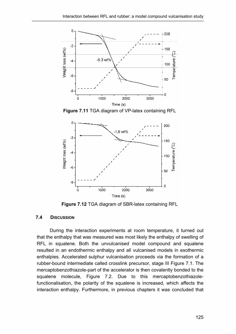
Interaction between RFL and rubber: a model compound vulcanisation study
Figure 7.11 TGA diagram of VP-latex containing RFL
Figure 7.12 TGA diagram of SBR-latex containing RFL
7.4 DISCUSSION
During the interaction experiments at room temperature, it turned out
that the enthalpy that was measured was most likely the enthalpy of swelling of RFL in squalene. Both the unvulcanised model compound and squalene resulted in an endothermic enthalpy and all vulcanised models in exothermic enthalpies. Accelerated sulphur vulcanisation proceeds via the formation of a rubber-bound intermediate called crosslink precursor, stage III Figure 7.1. The mercaptobenzothiazole-part of the accelerator is then covalently bonded to the squalene molecule, Figure 7.2. Due to this mercaptobenzothiazole-functionalisation, the polarity of the squalene is increased, which affects the interaction enthalpy. Furthermore, in previous chapters it was concluded that
125

Chapter 7
the VP-latex has a high affinity towards the mercoptobenzothiazole-containing accelerators.
Therefore, it is likely that squalene in the crosslink precursor state has an energetically more favourable interaction with RFL than unmodified squalene. This is confirmed by the fact that the model vulcanised for 20 minutes contained most crosslink precursors of all models, as judged from the HPLC experiments, Figure 7.6, and at the same time resulted in the highest exothermic swelling enthalpy: Table 7.5 and Figure 7.8.
When the RFL was prepared with SBR-latex, the absence of the VP-monomer resulted in a lower polarity of the RFL. Therefore the swelling enthalpy with the unvulcanised model compound turned exothermic. Functionalisation of squalene with the mercaptobenzothiazole accelerator, further increased the exothermic swelling enthalpy, indicating more favourable interactions between the model compound and this RFL.
7.5 CONCLUSIONS
Using HPLC technique, the compositions of several model compounds,
vulcanised for different periods of time, were determined. After 20 minutes of vulcanisation, the model compound contained many crosslink precursors, and after 30 minutes all sulphur and accelerators were consumed and MBT, a reaction product of vulcanisation, was detected indicating crosslink formation.
Temperature scans of the calorimeter were not useful because the heat flow was dominated by the evaporation of water from the RFL. However, the isothermal mixing measurements at room temperature turned out to give interesting results. The enthalpies detected by these mixing experiments were most likely swelling energies of RFL by the liquid model compound. The unvulcanised model compound resulted in endothermic enthalpies and all vulcanised model compounds in exothermic enthalpies. The model compound that was vulcanised for 20 minutes resulted in the highest exothermic swelling enthalpy. This was most probably caused by the fact that the polarity of the squalene molecules was increased by the covalently bonded, or grafted, accelerator moieties called crosslink precursors. When the model compounds were vulcanised for more than 20 minutes, the precursors turned into crosslinks and the polarity of squalene decreased again together with the mixing enthalpy. This was the case for both RFL containing VP-latex and SBR-latex.
In literature, squalene proved many times to be a reliable model for natural rubber. Therefore, it is expected that real rubber also has an optimum affinity towards the RFL-dip when it reaches the crosslink precursor state. However, this calorimetric setup cannot be used for real rubber systems. Therefore, the importance of the crosslink precursor state of the rubber compound on the formation of a sufficient bonding between RFL and rubber
126

Interaction between RFL and rubber: a model compound vulcanisation study
cannot be conclusively determined. However, the results described in this chapter point towards the occurrence of chain segment diffusion between latex and the rubber polymers at the moment that the rubber compound is in its precursor state. This can contribute to the final adhesion.
In Chapter 8, the interaction at different stages of vulcanisation is investigated between RFL and real rubber systems to shed further light on the conclusions from this chapter. 7.6 REFERENCES 1. D.B. Wootton, "The Application of Textiles in Rubber". 2001, Shawbury:
Rapra technology LTD. 2. W. Weening and W.H. Hupje, Kautsch. Gummi Kunstst., 25, 321-324
(1972). 3. A.Y. Coran, "Vulcanization", in Science and Technology of Rubber, F.R.
Eirich, Editor. 1978, Academic Press, New York. 4. N.J. Morrison and M. Porter, Rubber Chem. Technol., 57, 63-85 (1984). 5. G. Heideman, R.N. Datta, and J.W.M. Noordermeer, Rubber Chem.
Technol., 77, 512-541 (2004). 6. E. Garreta, N. Agullo, and S. Borros, Kautsch. Gummi Kunstst., 55, 82-
85 (2002). 7. S. Borros and N. Agullo, Kautsch. Gummi Kunstst., 53, 131-136 (2000). 8. S. Rodriguez, C. Masalles, N. Agullo, and S. Borros, Kautsch. Gummi
Kunstst., 52, 438-445 (1999). 9. G. Heideman, R.N. Datta, J.W.M. Noordermeer, and B.v. Baarle, J. Appl.
Polym. Sci., 95, 1388-1404 (2005). 10. F.K. Lautenschlaeger, Rubber Chem. Technol., 52, 213-231 (1979). 11. F.K. Lautenschlaeger, Rubber Chem. Technol., 52, 27-47 (1979). 12. G.P. McSweeney and N.J. Morrison, Rubber Chem. Technol., 56, 337-
343 (1983). 13. E.C. Gregg and S.E. Katrenick, Rubber Chem. Technol., 43, 549-571
(1970). 14. E.C. Gregg and R.P. Lattimer, Rubber Chem. Technol., 57, 1056-1097
(1984). 15. J.H.M.v.d. Berg, E.F.J. Duynstee, and P.J.D. Maas, Rubber Chem.
Technol., 58, 58-66 (1985). 16. J.H.M.v.d. Berg, J. Beulen, E.F.J. Duynstee, and H. Nelissen, Rubber
Chem. Technol., 57, 265-274 (1984). 17. J.H.M.v.d. Berg, J. Beulen, J.M.H. Hacking, and E.F.J. Duynstee,
Rubber Chem. Technol., 57, 725-734 (1984).
127

Chapter 7
18. M.M. Alvarez-Grima, Novel Co-agents for Improved Properties in Peroxide Cure of Saturated Elastomers, in Department of Engineering Technology. 2007, University of Twente: Enschede.
19. P. Versloot, J. Haasnoot, P. Nieuwenhuizen, J. Reedijk, M.V. Duin, and J. Put, Rubber Chem. Technol., 70, 106-119 (1997).
20. P. Versloot, J.G. Haasnoot, and J. Reedijk, Rubber Chem. Technol., 65, 343-349 (1992).
21. P. Versloot, J.G. Haasnoot, and J. Reedijk, Rubber Chem. Technol., 67, 263-279 (1994).
22. P. Versloot, J.G. Haasnoot, and J. Reedijk, Rubber Chem. Technol., 67, 252-262 (1994).
23. P.J. Nieuwenhuizen, Appl. Catal., A, 207, 55-68 (2001). 24. M. Geyser and W.J. McGill, J. Appl. Polym. Sci., 60, 431-437 (1996). 25. M. Geyser and W.J. McGill, J. Appl. Polym. Sci., 60, 439-447 (1996). 26. J.R. Wolfe, Rubber Chem. Technol., 41, 1339-1347 (1968). 27. W.v. Ooij and J.M. Kim, Rubber Chem. Technol., 75, 199-214 (2002). 28. R.N. Datta, A.H.M. Schotman, A.J.M. Weber, F.G.H.V. Wijk, P.J.C.V.
Haeren, J. Hofstraat, A.G.V.D. Bovenkamp-Bouwman, and A. Talma, Rubber Chem. Technol., 70, 129-145 (1997).
29. Y. Li, T. Wang, H. Balard, J. Donnet, and G. Burns, Rubber Chem. Technol., 75, 811-824 (2002).
30. S.H. Kim, B.Y.H. Liu, and M.R. Zachariah, Langmuir, 20, 2523-2526 (2004).
128

Chapter 8
Mechanism of curative migration from rubber to RFL-dip
The distribution of atomic sulphur and zinc through the RFL-rubber interface at different stages of vulcanisation is determined. A two-fold approach is used: quenching samples during the vulcanisation step of SEM-EDX sample preparation, respectively using pre-pressed rubber compounds for the samples. It turns out that both the atomic sulphur and zinc migrate in two phases: first being part of non-reactive species and subsequently being part of reactive species. During scorch, sulphur and ZnO migrate from rubber into the RFL-layer, but do not create enrichment and the steep penetration curves observed in previous chapters. The length of the scorch time is not critical, as judged from H-pullout experiments. After the scorch time is over, crosslink precursors convert to crosslinks in the rubber compound, releasing MBT. MBT subsequently reacts with ZnO to form a zinc-MBT complex. This complex is the most likely species to migrate from rubber to RFL, due to its high solubility towards the latex caused by the VP-monomer content. There, it rapidly crosslinks the latex with the sulphur that migrated at an earlier stage. The crosslink density of the latex formed at the RFL-rubber interface hampers further migration from rubber to dip and this results in the steep sulphur penetration pattern.

Chapter 8
8.1 INTRODUCTION Vulcanisation of a RFL-layer to a NR rubber compound results in an
enrichment of atomic sulphur in the RFL-dip at the RFL-rubber interface. The degree of enrichment has a strong influence on the resulting adhesion. In the studies described in previous chapters, the atomic sulphur enrichment was measured by SEM-EDX after vulcanisation was complete. In this chapter, a detailed study into the formation of this sulphur enrichment during vulcanisation is described. To understand what kind of species may be migrating, a brief introduction will be given about accelerated sulphur vulcanisation.
A generally accepted mechanism of accelerated sulphur vulcanisation chemistry is shown in Figure 8.1.1, 2
Accelerator + ZnO
Zinc-accelerator complex
Acc-Sx-Zn-Sx-Acc or polysulphidic accelerator complex
Rubber-Sy-Acc
Rubber-Sy-Rubber
Rubber-Sz-Rubber
S8
Rubber
(I)
(II)
(III)
(IV)
(V) Figure 8.1 General scheme of vulcanisation2
According to this mechanism, there are five stages of vulcanisation.
Initially, the accelerators dissociate under the influence of the activator ZnO, forming a zinc-accelerator complex. This complex interacts with sulphur and forms a polysulphidic complex that can recombine to polysulphidic MBTS, when using an accelerator of the mercapto-benzothiazole type. The most probable3 structure of this complex is shown in Scheme 8.1.
130

Mechanism of curative migration from rubber to RFL-dip
N
SSSx
N
SS
Zn2+
NH2NH2
Scheme 8.1 Complex formation of the accelerator with ZnO3
From these polysulphidic species, rubber bound intermediates called
crosslink precursors are formed; this reaction is shown in Scheme 8.2.1 MBT is a product of this reaction and can participate again in the formation of a complex.
N
S
N
SS
SSx
N
SS
H
N
SSH
CH
H
C
CH
CH3
Sx
CH
CH3
S+
(Crosslink precursor)
(MBT)
Scheme 8.2 One postulated mechanism of formation of crosslink precursor from a rubber chain and polysulphidic MBTS1
Crosslink precursors react with other precursors or with rubber polymers
to form polysulphidic crosslinks4: Scheme 8.3. Coran1 stated that crosslinking occurs when virtually all polysulphidic accelerator is consumed. The crosslinking reaction results in the formation of a MBT molecule. MBT does react with ZnO into a mobile zinc-MBT reaction product.3, 5, 6
After these initial crosslinks are formed, they can desulphurate to form shorter crosslinks or degrade to cyclic sulphides7.
131
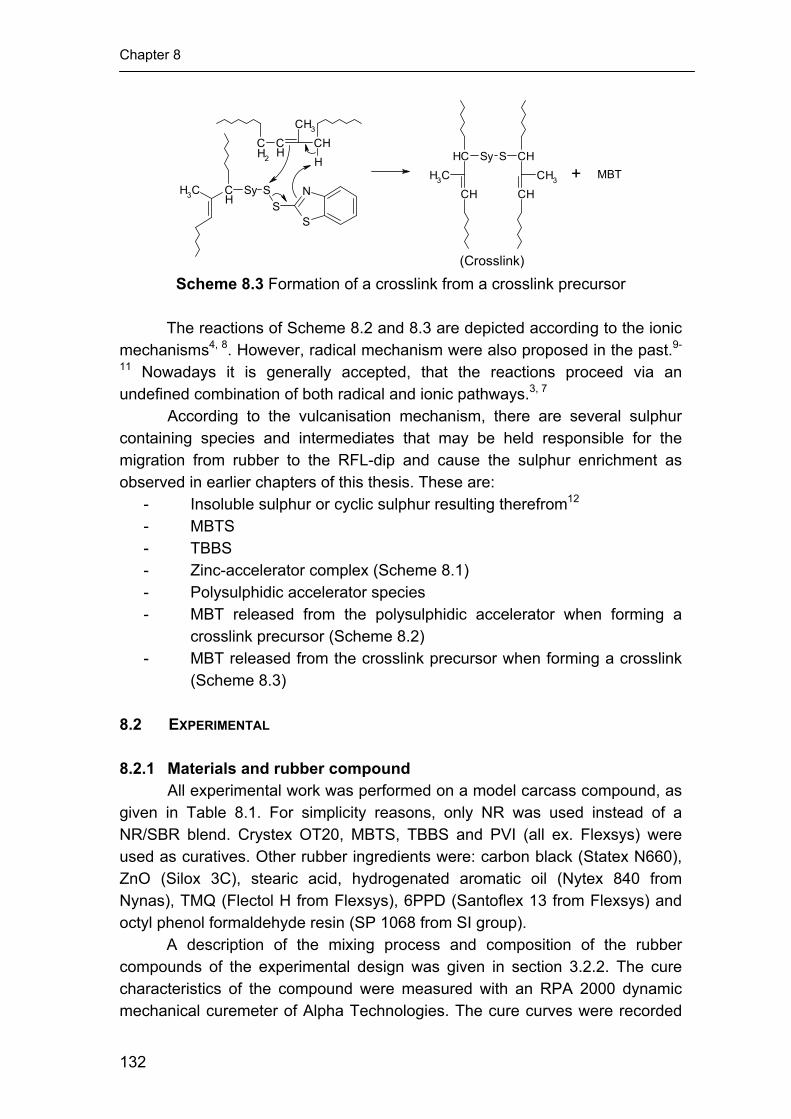
Chapter 8
CH
CHCH3
CH2 H
S
NCH
CH3 Sy SS
CH
CHCH3
CH
CHCH3
Sy S
+ MBT
(Crosslink) Scheme 8.3 Formation of a crosslink from a crosslink precursor
The reactions of Scheme 8.2 and 8.3 are depicted according to the ionic
mechanisms4, 8. However, radical mechanism were also proposed in the past.9-
11 Nowadays it is generally accepted, that the reactions proceed via an undefined combination of both radical and ionic pathways.3, 7
According to the vulcanisation mechanism, there are several sulphur containing species and intermediates that may be held responsible for the migration from rubber to the RFL-dip and cause the sulphur enrichment as observed in earlier chapters of this thesis. These are:
- Insoluble sulphur or cyclic sulphur resulting therefrom12 - MBTS - TBBS - Zinc-accelerator complex (Scheme 8.1) - Polysulphidic accelerator species - MBT released from the polysulphidic accelerator when forming a
crosslink precursor (Scheme 8.2) - MBT released from the crosslink precursor when forming a crosslink
(Scheme 8.3) 8.2 EXPERIMENTAL 8.2.1 Materials and rubber compound
All experimental work was performed on a model carcass compound, as given in Table 8.1. For simplicity reasons, only NR was used instead of a NR/SBR blend. Crystex OT20, MBTS, TBBS and PVI (all ex. Flexsys) were used as curatives. Other rubber ingredients were: carbon black (Statex N660), ZnO (Silox 3C), stearic acid, hydrogenated aromatic oil (Nytex 840 from Nynas), TMQ (Flectol H from Flexsys), 6PPD (Santoflex 13 from Flexsys) and octyl phenol formaldehyde resin (SP 1068 from SI group).
A description of the mixing process and composition of the rubber compounds of the experimental design was given in section 3.2.2. The cure characteristics of the compound were measured with an RPA 2000 dynamic mechanical curemeter of Alpha Technologies. The cure curves were recorded
132

Mechanism of curative migration from rubber to RFL-dip
at 150ºC, with a frequency of 0.833 Hz and 0.2 degrees strain. To judge the extent of pre-vulcanisation of the pre-pressed rubber compounds, the following output of the RPA was used: t2 and S’min. This S’min will be referred to as S’min,pr. The value of S’min,pr is normalised to the value of S’max,pr of the same cure curve. The closer the value of S’min,pr/S’max,pr is to 1, the closer the final vulcanisation state is reached during pre-vulcanisation. Table 8.1 Composition of the Carcass compound Component Amount (phr) NR SIR CV 60 100 Carbon black (N-660) 40 ZnO 3 Stearic acid 2 Hydrogenated aromatic oil (Nytex 840) 13
TMQ 0.5 6 PPD 1 Octyl-phenol formaldehyde resin 4 Sulphur 2.5 MBTS 0.5 TBBS 1 PVI 0.1 8.2.2 Fibre treatment
The p-aramid fibres were dipped twice: initially with an epoxy predip followed by a RFL-dip. The composition of the epoxy predip solution is depicted in Table 8.2; the solid content was 2 wt%. The preparation of the RFL-dip was carried out in two stages. First, a resorcinol formaldehyde resin solution was made and matured for 5 hours at 25°C. Second, latex and more water were added to obtain a RFL-dip with a solid content of 17 wt%. The compositions of the resin solution and the total RFL-dip are shown in Table 8.2. The type of latex used for preparing the RFL-dip for the SEM-EDX measurements was styrene-butadiene-2-vinylpyridine terpolymer latex obtained from Eliokem (Pliocord 106s). For the adhesion measurements both the commercial VP latex and commercial SBR latex, Intex 084 from Enichem, were investigated.
The cord was pretreated by passing through the predip-container and through two ovens: the first with a temperature of 150°C, the second 240°C. Residence times were 120 and 90 seconds, respectively. Subsequently, the cord was passed through the RFL-dip container. The RFL-layer on the cord was cured in a third oven at 235°C for 90 seconds. In every oven a tensile force of 8.5 N was applied to the cord.
133

Chapter 8
Table 8.2 Composition of the epoxy predip and the RFL-dip Component Amount (g) Solid (g) Epoxy predip
Water 978.2 - Piperazine 0.50 0.50
Aerosol OT (75%) 1.3 0.98 GE-100 epoxide 20.0 20.0
Total 1000 21.48 Resin solution
Water 4305 - NaOH (5%) 239.9 12.0 Resorcinol 181.3 181.3
Formaldehyde (37%) 274.3 101.49 Total 5000.5 294.8
RFL-dip Water 466.9 -
Latex (40%) 908.4 363.4 Resin solution 1124.7 66.31
Total 2500 429.7 8.2.3 Adhesion measurements to pre-pressed rubber
Rubber compounds were pre-pressed for different periods of time in a press at 150°C. For adhesion measurements, approximately 0.5 kg of compound is required. Because of this large quantity, no mould could be used, so that the slab of rubber was put directly between the press plates, only covered by aluminium foil. Because of this setup, no large force could be applied to the rubber. Therefore, the press plates were closed to the position that they just touched both sides of the rubber slab. After a definite period of time, the rubber was removed from the press and quenched in an ice bath.
The H-pullout measurements of dipped cords to the pre-pressed rubber compounds were performed as set out in ASTM D4776-98. Two presses were used for preparing the H-pullout samples: one at 50°C, the other at 150°C. The moulds with H-pullout samples were placed in the first press at 50°C for 30 minutes to ensure a good contact between rubber and RFL-treated fibres while the amount of curing reaction is negligible. After the first press, the moulds were put directly in the second press where vulcanisation took place. The vulcanisation time for this experiment was adjusted to t90 plus 9 minutes. The t90 from the RPA measurements of the pre-vulcanised rubber was used. The maximum force recorded during the pullout test is referred to as pullout force. Each H-pullout value is the average of 40 measurements.
Because H-pullout measurements require the rubber compound to flow around the cords during vulcanisation in the press, it was expected that at high pre-pressing times the flow is limited so much that a low quality sample would be obtained. For the Single End Strip Adhesion (SESA) test, this problem was not expected because the RFL-treated cords are vulcanised in the surface of a rubber slab, as depicted in Figure 8.2. Just as the H-pullout samples, the SESA
134

Mechanism of curative migration from rubber to RFL-dip
samples were first pressed at 50°C for 30 minutes before vulcanisation that took place at 150°C for the duration of t90 plus 9 minutes. At one side of the sample, a plastic foil separates a few centimetres of the cords from the rubber during vulcanisation. This part of the cords is used for clamping in the tensile tester. The cords are then peeled out of the surface of the rubber compound one by one at an angle of close to 180°. The pulling rate was 100 mm/min and the average force between the displacement of 80 and 180 mm was referred to as SESA force. The value of the SESA force is the average of 6 measurements.
rubber slab
cords embedded in the surface
Figure 8.2 Schematic representation of the SESA test
8.2.4 SEM-EDX measurements during vulcanisation
By monitoring the distribution of atomic sulphur through the RFL-rubber interface at different stages of vulcanisation, it can be investigated at what moment the enrichment occurs and derived therefrom what exactly the migrating species are. Two different experimental approaches were used to address this.
The first approach was to bring unvulcanised rubber into contact with a layer of RFL on aluminium foil and vulcanise this in the press for a definite period of time that varied from 30 to 540 seconds. After 540 seconds vulcanisation is complete. After the appropriate time, the sample is quenched in an ice bath. A major difference in SEM-EDX sample preparation procedure from the one described in Chapter 4 is, that a tensile test mould was used instead of a compression set mould. The tensile test mould comprises a larger area than the RFL-spot on the aluminium foil: approximately 1 cm2. Therefore, a part of the rubber in the mould did not touch the RFL-layer during the pressing treatment. This part was later on used in the RPA 2000 to determine the vulcanisation state of the rubber. The part of the sample with contact
135

Chapter 8
between rubber and RFL-dip was investigated by SEM-EDX for sulphur and zinc migration.
The second approach was to put RFL into contact with rubber compounds that were already pressed at 150°C and quenched after definite periods of vulcanisation time. For this pre-pressing, also a tensile test mould was used. A part of the pre-pressed rubber compounds was used to determine the vulcanisation state and a small part was put back again in the press at 150°C to finish the cure against a RFL-layer for the remainder of t90 plus 9 minutes.
The SEM-EDX equipment used was a LEO 1550 FEG/ Thermo Noran Instruments, model Vantage. The accelerating voltage was 15 kV and the sample distance was 9 mm. For this study, the diaphragm of the EDX was set to 60 µm instead of the usual 30 µm. To avoid drifting of the sample and burning its surface due to this large diaphragm setting, the samples were coated twice with carbon to raise the conductivity. 8.3 RESULTS 8.3.1 Adhesion measurements during vulcanisation H-pullout measurements: - Eight rubber compounds, all with the formulation as given in Table 8.1, were pre-pressed and partly vulcanised at 150°C for periods of time varying from 0 to 450 seconds. After this pre-pressing, the compounds were quenched and the cure state was analysed using a rheometer. The results are shown in Figure 8.3. The values for the minimum torque are indicative of the amount of crosslinks that are formed during the pre-pressing period. These values are normalised to the maximum torque of the rheogram. The closer this normalised value is to 1, the closer the compound reached the final vulcanised state during the pre-pressing period. The highest value in Figure 8.3 is 0.4 at a pre-pressing time of 450 seconds. Hardly any crosslinks are formed between 0 and 300 seconds, judging from Figure 8.3. The scorch time decreased gradually with increasing pre-pressing time over the whole range.
136

Mechanism of curative migration from rubber to RFL-dip
Figure 8.3 RPA results of the pre-pressed compounds for H-pullout
measurements The H-pullout results of the pre-pressed compounds after vulcanisation against the cords in the second step, are shown in Figure 8.4A for the RFL-treated fibres with VP-latex and 8.4B for the SBR-latex. The level for the SBR-latex is much higher than the level for the VP-latex; this corresponds to the results discussed in Chapter 6. For both latices, the H-pullout force does not decrease when the rubber is pre-pressed for 300 seconds or less, but remains at a value of around 70 N for the VP-latex and 140 N for the SBR latex. However, pre-pressing the rubber compound for 450 seconds resulted in a significant decrease in H-pullout force for both the VP- and SBR-latices. One of the possible causes could be that the rubber cannot fully cover the fibres anymore due to a lack of flow, because the rubber is partly crosslinked as judged from Figure 8.3.
A B
Figure 8.4 H-pullout results of the pre-pressed rubber compounds to RFL-treated cords; A: RFL with VP-latex; B: RFL with SBR-latex
137

Chapter 8
For SESA tests, the flow characteristics of the rubber compounds are expected to have a small influence on the result, because the fibres are vulcanised on top of the surface of a rubber slab. A total of four compounds was pre-pressed for 30, 120, 240 and 360 seconds and subsequently quenched in an ice bath.
The cure characteristics of the resulting pre-pressed compounds are shown in Figure 8.5. Until a pre-pressing time of 240 seconds, the scorch time decreases but the ratio of the minimum and maximum torque hardly increases. The compound pre-pressed for 360 seconds results in a ratio of around 0.25, indicating that crosslinks were formed during the pre-pressing time.
Figure 8.5 RPA results of the pre-pressed compounds for SESA
measurements The SESA results for the pre-pressed compounds are shown in Figure
8.6. When RFL is prepared with VP-latex, Figure 8.6A, the SESA force decreases slightly with increasing pre-pressing time from 30 to 240 seconds. However, after pre-pressing for 360 seconds, the SESA force increases significantly to a value of around 8 N. With SBR-latex in the RFL, this increase is not observed; the SESA force decreases with increasing pre-pressing time over the whole range: Figure 8.6B. Despite this decrease, the SESA force of the RFL prepared with SBR-latex remained at a much higher level than the one prepared with VP-latex, over the whole range of pressing times.
138

Mechanism of curative migration from rubber to RFL-dip
A B
Figure 8.6 SESA results of the pre-pressed rubber compounds vulcanised onto RFL-treated cords; A: RFL with VP-latex; B: RFL with SBR-latex
8.3.2 Curative migration during vulcanisation
Figure 8.7 shows a typical linescan through a RFL-rubber interface after complete vulcanisation of the rubber compound. Both atomic sulphur and zinc show enrichments at the RFL-rubber interface, as was already shown in Figure 4.7 of Chapter 4. The present purpose is to investigate at which stage of vulcanisation this enrichment occurs and what the migrating species exactly are.
Figure 8.7 SEM-EDX linescan through the RFL-rubber interface; left of the
dotted line is the RFL-dip and right the rubber compound Quenching RFL-rubber samples during vulcanisation and measure the sulphur and zinc migration: - The first approach to investigate the migration during vulcanisation was to quench the RFL-rubber samples for the SEM-EDX after
139

Chapter 8
different periods of time during the pressing step of the sample preparation. Rubber was vulcanised for various times to RFL on aluminium foil in a tensile test mould. This mould comprises an area much larger than that of the RFL-layer. After quenching, the rubber that surrounded the RFL-layer, but did not touch it, was analysed by RPA for the state of cure and the RFL-rubber interface was analysed by SEM-EDX for sulphur and zinc migration. The results for the RPA measurements are shown in Figure 8.8. Although the rubber samples were thinner than the ones used for the H-pullout and SESA tests, and a pressure of 100 bar was applied, Figure 8.8 shows a close resemblance to Figures 8.3 and 8.5. The scorch time decreased with increasing pressing time up to 300 seconds. When pressing the rubber longer than 300 seconds, the scorch time stabilised at a value of approximately 0.25 minutes. Up to a pressing time of 180 seconds, the values for the minimum and maximum torque did not change. This indicates that during the first 180 seconds in the press, the rubber hardly forms any crosslinks. At a pressing time of 300 seconds, crosslinks started to be formed and the value of S’min,pr/S’max,pr increased further as a function of pressing time till practically fully crosslinked.
Figure 8.8 RPA results for the rubber-part of the quenched SEM-EDX samples,
that did not touch the RFL-layer The linescan through the RFL-rubber interface of the sample that was in contact with the rubber compound for a short period of time, 30 seconds only, is shown in Figure 8.9. SEM-EDX sample preparation was possible even though the rubber was hardly vulcanised at all. After RFL to rubber contact in the press for 30 seconds, clearly sulphur and zinc have moved from the rubber to the RFL. Remarkably, there was no enrichment of either sulphur or zinc at the RFL-rubber interface. The level of atomic sulphur in the RFL-dip is slightly lower than in the rubber compound: 400 to 500 counts. The amount of zinc counts in the RFL-dip is 100 to 200 counts.
140

Mechanism of curative migration from rubber to RFL-dip
Figure 8.9 SEM-EDX linescan through the RFL-rubber interface after the RFL and rubber were in contact in the press for 30 seconds; left of the dotted line is
the RFL-dip and right the rubber compound Figure 8.10 shows the linescans through the RFL-rubber interfaces of the samples that were quenched after 90, 120, 180, 300, 420 and 540 seconds of vulcanisation. The dotted lines indicate the interface between RFL, on the left, and rubber, on the right. The linescans of the samples that were pressed for 90 and 120 seconds resulted in an atomic sulphur content in the RFL-layer of 400 to 500 counts, similar to the counts for 30 seconds: Figure 8.9. For these two samples there was still no enrichment but a horizontal sulphur pattern. There was also no enrichment observed at the interface for the 180 seconds pressed samples, but the overall level of atomic sulphur in the RFL-layer was slightly increased: 500 to 600 counts. Figure 8.8 showed that in these three samples hardly any crosslinks were formed yet. Therefore, it can be deduced that during the scorch time, when no crosslinks are formed yet in the rubber phase, the sulphur enriching species were not yet formed. After 300 seconds, when crosslinks start to be generated in the rubber compound, Figure 8.8, the first clear signs of enrichment are observed at the RFL-rubber interface: Figure 8.10D. However, the amount of sulphur counts at the interface is not yet as high as the amount that was formed after complete vulcanisation: Figure 8.7. From Figures 8.10E and 8.10F, it can be further deduced that the degree of enrichment increases with increasing pressing time. After a pressing time of 540 seconds, the resulting linescan is very similar to the one obtained after complete vulcanisation: Figure 8.7.
141
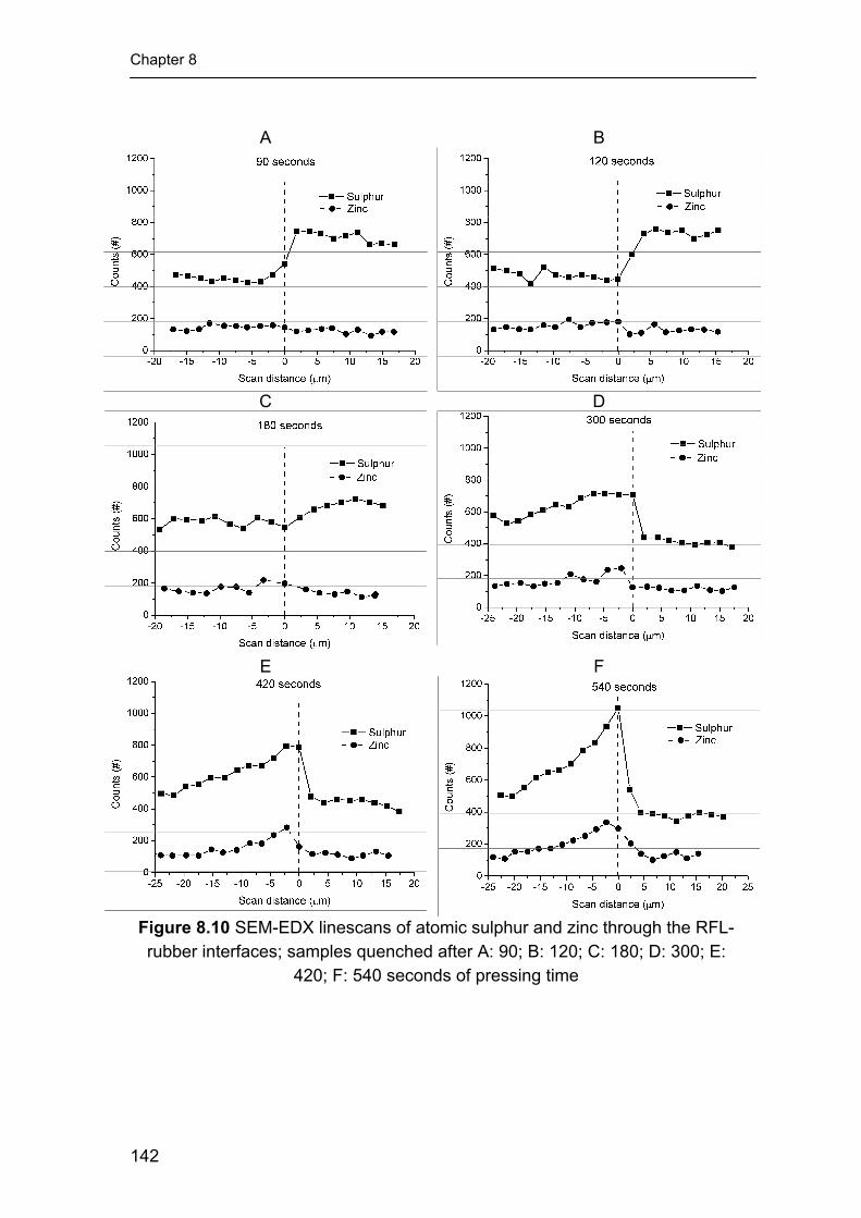
Chapter 8
A B
C D
E F
Figure 8.10 SEM-EDX linescans of atomic sulphur and zinc through the RFL-rubber interfaces; samples quenched after A: 90; B: 120; C: 180; D: 300; E:
420; F: 540 seconds of pressing time
142

Mechanism of curative migration from rubber to RFL-dip
The development of the zinc pattern proceeds in a very similar manner as the one of sulphur. During the first 180 seconds, no enrichment of zinc is observed. The level of zinc was slightly higher in the RFL than in the rubber. This is caused either by zinc itself, or possibly by sodium hydroxide used for preparing the resin solution for the RFL-dip. Sodium shares the position with zinc in the EDX spectrum, as already explained in section 4.3.1. At a pressing time of 300 seconds, a small enrichment is observed and the degree of enrichment increases further with increasing pressing time. Curative migration of pre-pressed rubber to RFL: - The second approach to investigate the migration of curatives from rubber to RFL-dip during vulcanisation was to pre-press rubber compounds for different periods of time without being in contact with a layer of RFL. After the pre-pressing time, vulcanisation was stopped by quenching the rubber compound in ice. Using the RPA, the vulcanisation state was determined. The quenched pre-pressed rubber was then further vulcanised in the press against an RFL-layer on aluminium until the cure was complete. SEM-EDX was used again to analyse the RFL-rubber interface. Like Figures 8.3 and 8.5, Figure 8.11 shows the RPA results for the quenched rubber compounds. Pre-pressing the rubber for 180 seconds decreases the scorch time but hardly any crosslinks are formed yet, as judged from the value for S’min,pr/S’max,pr. During the pre-pressing periods of 300 and 420 seconds, crosslinks are formed. It was not possible to create SEM-EDX samples from rubber compounds pre-pressed for more than 420 seconds, due to the advanced vulcanisation state and the resulting lack of rubber flow.
Figure 8.11 RPA results of the pre-pressed rubber compounds before
vulcanising to a RFL-layer
143

Chapter 8
Figure 8.12 shows the linescans for atomic sulphur of the RFL-rubber interfaces for the three rubber compounds that were pre-pressed before vulcanising to RFL-layers. The rubber compound that was pre-pressed for a period of 180 seconds shows no difference in comparison with the linescan obtained with the rubber compound that was not pre-pressed: Figure 8.7. The 300 seconds pre-pressed rubber compounds resulted in a linescan with a similar slope as the 180 seconds pre-pressed compound, but at the side of the RFL-layer the linescan is positioned approximately 150 counts lower. The same conclusion can be drawn from the linescan of the 420 seconds pre-pressed compound: this linescan also has a similar slope and is positioned 400-500 counts lower than that of the 180 seconds pre-pressed compound.
Figure 8.12 SEM-EDX linescans for atomic sulphur through interfaces between RFL and rubber compounds, that were pre-vulcanised in the press for 180, 300
and 420 seconds The results for the zinc content of the three compounds are shown in Figure 8.13. The results for zinc are similar to those for sulphur. All three compounds show comparable slopes of the linescans, but the general level of the zinc counts decreases with increasing pre-pressing time. The difference between the 180 seconds and the 420 seconds pre-pressed compounds is between 100 and 200 counts.
144

Mechanism of curative migration from rubber to RFL-dip
Figure 8.13 SEM-EDX linescans for zinc through interfaces between RFL and
rubber compounds that were pre-pressed for 180, 300 and 420 seconds 8.4 DISCUSSION
When heat is applied during pressing or pre-pressing of the voluminous
rubber compound in the press, the rubber does not reach the applied 150°C throughout the whole thickness instantaneously because of physical limitations of heat transport. Using the RPA, the vulcanisation state of the bulk of the rubber was determined while it is the surface of the rubber specifically that is in contact with the RFL-dip during the preparation of the adhesion and the SEM-EDX samples. For the adhesion samples, both H-pullout and SESA, this effect is expected to be more pronounced because the thickness of the pre-pressed rubber slabs was 1 to 2 cm. The thickness of the rubber during the preparation of the SEM-EDX samples was 2 mm because a tensile test mould was used. Despite this intrinsic limitation, the assumption has to be made that the vulcanisation state on the surface of the rubber was equal to that of the bulk. 8.4.1 Adhesion measurements to pre-pressed rubber compounds
From the H-pullout results, it can be concluded that adhesion is not influenced at all when the RFL-treated cords were not in contact with the rubber compound during the scorch period. This agrees with Chapter 3, where the conclusion was drawn that the scorch time of the rubber compound is not a dominant factor regarding adhesion.
The pre-pressed rubber compound in which crosslinks were already formed, on the other hand, lacked the ability to flow around the RFL-treated cords and resulted therefore in a low H-pullout force. This lack of flow was not a major problem for the SESA test, because for this adhesion test the RFL-treated cords were vulcanised on top of a rubber slab and hardly any flow of the rubber compound was required to fill the cavities of the mould. When VP-latex
145

Chapter 8
was used in the RFL-dip, the SESA adhesion force turned out to be higher for the rubber compound with crosslinks than for the other compounds. In Chapter 6, it was concluded that, for VP-latex the degree of enrichment of atomic sulphur at the RFL-rubber interface was inversely related to the adhesion, when the change in enrichment was caused by the accelerator of the rubber compound. When using RFL with SBR-latex, there was hardly any enrichment at all, as discussed in Chapter 6 as well. The increase in SESA force for the VP-latex containing RFL-dip may be explained therefore by the fact that less curatives migrate from rubber to the RFL-layer when the rubber is partly crosslinked, resulting in a lower degree of sulphur enrichment. For the RFL-dip with SBR-latex, there was hardly an enrichment to begin with, and the SESA force decreased with increasing pre-pressing time over the whole range. 8.4.2 Curative migration from rubber to RFL-dip during vulcanisation Migration of reactive sulphur containing species: - The interpretation of the atomic sulphur signal in particular is quite complex because the atom sulphur is present in S8, contained in both accelerators as part of the molecule, and in reaction products and crosslinks. One of the conclusions of Chapter 5 was that apparently migrating sulphur-containing species were formed during vulcanisation. This is now verified by the fact that no enrichment is observed after 30, 90, 120 and 180 seconds of vulcanisation: Figures 8.9 and 8.10. Another conclusion of Chapter 5 was that the resin-type of the RFL does not have any influence on the slope of the sulphur penetration curve. The slope occurs because there must be a competition between diffusion and reaction of certain reactive species with the VP-latex. Sulphur containing species are formed, reactive upon entering the RFL-layer, thus causing an increase of the atomic sulphur level at the RFL-rubber interface. These species subsequently immediately react with the VP-latex in the form of crosslinking, leaving the sulphur behind, in this way forming the concentration gradient into the RFL-layer. From Figures 8.10D, 8.10E and 8.10F, it can be concluded that the sulphur counts in the RFL-layer directly at the RFL-rubber interface increases with increasing vulcanisation time, reaching the highest value after 540 seconds of vulcanisation, corresponding to t90 of the rubber compound. This indicates that the concentration of this reactive species in the rubber compound itself also increases continuously during vulcanisation. Therefore, these reactive migrating species cannot be an intermediate such as the zinc-accelerator complex formed in stage I of Figure 8.1, but it must be a reaction product. Furthermore, the enrichment is observed at the same moment that crosslinks start to be formed in the rubber compound: compare Figure 8.8 with 8.10. The reaction product that is formed when a crosslink precursor reacts into a full crosslink is the MBT-molecule: Scheme 8.3. Another observation from Figure 8.10 is that zinc and sulphur create enrichment at the same moment
146

Mechanism of curative migration from rubber to RFL-dip
during vulcanisation. MBT is known to react with ZnO to form a zinc-MBT complex.3, 5, 6 According to Ghosh3, this is a stable and mobile complex. Therefore, this zinc-complex is most likely the migrating species. The zinc-MBT-complex contains sulphur atoms and contributes to the EDX sulphur signal. Furthermore, the solubility parameter calculations from Chapter 6 already indicated that mercapto-benzothiazole based accelerators have a high solubility towards the vinylpyridine monomer of the VP-latex, which also explains the driving force of the zinc-MBT complex to migrate from rubber to dip. Migration of unreactive species from rubber to RFL-dip: - After 30 seconds, Figure 8.9, and for the rest of the scorch period, Figures 8.10A and 8.10B, both the sulphur and zinc linescans from the RFL-rubber interface into the RFL-layer are horizontal. The horizontal patterns indicate that the species causing these signals are relatively unreactive in the VP-latex. In Figure 8.12, the sulphur concentration at the RFL-rubber interface decreases and in Figure 8.13 the zinc behaves the same. However, the steepness of the penetration gradients for both sulphur and zinc remains the same for all three samples. This unchanged slope indicates that the reactive zinc and sulphur-containing species did enter the RFL-layer, but the RFL lacks other sulphur- and zinc-containing species. This can be explained by the fact that the RFL-layer has not been into contact with the rubber at stage I, II and III of Figure 8.1, and that the relatively unreactive migrating species (for example sulphur itself) at that stage did not have a chance to enter the RFL-layer. The difference in counts on the RFL-side of the interface between the 180 seconds pre-pressed rubber and the 420 seconds one is 400 to 500 sulphur counts and 100 to 200 zinc counts. These differences are the same as the number of sulphur and zinc counts present in the RFL-layer after only 30 seconds of vulcanisation: Figure 8.9. It is not likely that after 30 seconds of vulcanisation, a significant amount of sulphur-and zinc-containing species or reaction products have been formed. Therefore, the 400 to 500 sulphur counts are most probably caused by migration of sulphur, S8, and the 100 to 200 zinc counts by the migration of ZnO even in this short contact time already. Both sulphur and ZnO on their own are not reactive in a rubber compound, but do react when a zinc-MBT complex enters the RFL-layer at a later stage during the vulcanisation process. 8.5 CONCLUSIONS
During the scorch time of the rubber compound, sulphur and ZnO
migrate from rubber to the RFL-layer. Because both sulphur and ZnO are hardly reactive towards the RFL-latex, a horizontal penetration pattern is
147

Chapter 8
observed. H-pullout measurements show that the duration of the scorch time is not a critical factor; the H-pullout force remains at the same level even though the scorch time decreases due to the pre-pressing treatment of the rubber compounds.
After the scorch time is over and crosslinks start to be formed from crosslink precursors in the rubber compound, zinc-MBT complexes are formed. These zinc-MBT complexes are the most likely species to migrate from rubber into the dip, due to a high solubility towards the VP-latex, where it meets the sulphur that already migrated at an earlier stage. The sulphur and the zinc-MBT complexes react rapidly with the allylic hydrogens of the latex, and crosslinks are formed between the latex polymer chains. Due to the high amount of zinc-MBT complexes at the interface, the local crosslink density is high, as concluded from the nano-indentation experiments of Chapter 4. The steep penetration curve into the RFL-layer is most likely caused by lack of further migration of more zinc-MBT complexes due to the local high crosslink density at the interface, which is known to impede migration in rubbers.
8.6 REFERENCES 1. A.Y. Coran, "Vulcanization", in Science and Technology of Rubber, F.R.
Eirich, Editor. 1978, Academic Press, New York. 2. N.J. Morrison and M. Porter, Rubber Chem. Technol., 57, 63-85 (1984). 3. P. Ghosh, S. Katare, P. Patkar, J.M. Caruthers, and V.
Venkatasuramananian, Rubber Chem. Technol., 76, 592-693 (2003). 4. A.Y. Coran, "Vulcanization", in Science and Technology of Rubber, F.R.
Eirich, Editor. 1994, Academic Press, New York. 5. M.H.S. Gradwell and W.J. MsGill, J. Appl. Polym. Sci., 51, 177-185
(1994). 6. M.H.S. Gradwell and M.J.v.d. Merwe, Rubber Chem. Technol., 72, 55-64
(1999). 7. G. Heideman, R.N. Datta, and J.W.M. Noordermeer, Rubber Chem.
Technol., 77, 512-541 (2004). 8. L. Bateman, C.G. Moore, and M. Porter, J. Chem. Soc., 2866-2879
(1958). 9. E.H. Framer and F.W. Shipley, J. Appl. Polym. Sci., 1, 293 (1946). 10. E.H. Framer, J. Chem. Soc., 1519 (1947). 11. E.H. Framer, J. Soc. Chem. Ind., 66, 86 (1947). 12. N.M. Huntink, PhD thesis, Department of science and technology. 2003,
University of Twente: Enschede.
148

Chapter 9
Summary and evaluation of the results
The results of the research described in this thesis are summarised in this chapter. The results and conclusions of all chapters are evaluated and this chapter ends with some concluding remarks and suggestions for further research.

Chapter 9
9.1 MOTIVATION
Reinforcement of rubber by cords is crucial for many applications such
as high-pressure hoses and conveyor belts. However, the largest application of cord-rubber composites is the tyre. The carcass of the tyre contains a network of cords that gives the tyre its strength. Not only the type of cord material that is used determines the performance, but also the way the cords are positioned in the carcass, as described in Chapter 1. Since the cords absorb most of the forces where the tyre is subjected to, a good adhesion between cord and rubber is an absolute requirement.
The coating which the cords need to obtain sufficient adhesion to rubber compounds is called the Resorcinol Formaldehyde Latex (RFL) treatment. Despite the importance of good adhesion and the fact that this RFL-treatment has been widely applied since the Second World War, and no better alternative has been found till today, the mechanism by which the adhesion is obtained has remained unclear. The relatively few publications on this technique are described in Chapter 2. Most of the research described was rather empirical: the many factors involved when dipping the cords in a RFL-dip and curing it to rubber were varied and their influence on the adhesion was described. However, most of the publications lack a mechanistic approach to obtain more fundamental knowledge about this technique.
With new fibre materials introduced in recent years, in particular aramid fibres, there is a renewed interest in the mechanism of adhesion of RFL-treated cords to rubber in order to utilise the properties of these high-performance fibres to their full extent in rubber compounds. In this thesis, an attempt is made to elucidate the adhesion between RFL-treated cords and rubber using a more systematic approach to obtain a mechanistic view on the chemical and physical processes involved. 9.2 GENERAL EVALUATION OF THE RESULTS
The study described in this thesis focuses on the interface between the
RFL-layer and the rubber compound. It turned out that the distribution of rubber curatives across this interface plays a key role in the adhesion. The fact that these curatives migrate from the rubber compound into the dip (Chapter 4) was published before, as well as the fact that the optimum cure time, t90, of the rubber compounds correlate with the adhesion (Chapter 3). Several researchers connected these two observations and stated, that the positive effect of a large t90 was related to the fact that there would be more time available for the rubber curatives to migrate from rubber to the RFL-dip, and consequently co-vulcanise these two materials. However, the work described in
150

Summary and evaluation of the results
Chapter 4 indicates that rubber compounds with a small t90 provide a higher atomic sulphur content in the RFL-dip, measured by SEM-EDX, compared to compounds with a large t90. The atomic sulphur content in the dip originates from the rubber curatives, since the RFL-dip itself does not bring along any sulphur before vulcanisation. Furthermore, the atomic sulphur content directly at the RFL-rubber interface increases significantly with increasing accelerator dosage in the rubber compound. These observations lead to the conclusion that the migration mechanism is not related to time-limited diffusion, but rather to a solubility phenomenon.
In Chapter 5, EDX experiments are performed on the interface between rubber and latex layers; these layers can be considered as RFL-layers without any resin present. These experiments show that the latex component of the RFL-dip is responsible for the high solubility towards the rubber curatives. Solubility parameter calculations described in Chapter 6 indicate that particularly the vinylpyridine (VP)-monomer of the latex causes this high solubility. This is verified in the same chapter by EDX-experiments on RFL-dips containing commercial SBR- and VP-latex, and on RFL-containing model-latices of which the polymers consist of increasing VP-monomer contents. For NR-compounds, increasing VP-content raises the level of atomic sulphur in the RFL-layer directly at the RFL-rubber interface. This increasing atomic sulphur content is accompanied by a decreasing H-pullout force. This corresponds to the results of Chapter 4.
Experiments described in Chapter 6 illustrate that there is an optimum amount of zinc-MBT complexes at the RFL-rubber interface regarding the adhesion. Using SBR-latex in the RFL formulation, there is no enrichment at the RFL-rubber interface like there is for the VP-latex. Decreasing the amount of accelerators in the rubber compound decreases the adhesion. This indicates that a certain amount of zinc-MBT complexes is still beneficial for the adhesion.
Model compound vulcanisation studies described in Chapter 7 show that not only the solubility of curatives but also the mutual affinity between the latex and rubber polymers must be taken into consideration. Using a mixing calorimeter to analyse the interaction energies, it turns out that the rubber-model, squalene, shows a maximum affinity to RFL when it is in its crosslink precursor state. In fact, unvulcanised squalene results in an endothermal interaction energy and the squalene in the crosslink precursor state in an exothermal one. Unfortunately, with this experimental setup it was not possible to analyse real rubber systems. Therefore, the importance of the crosslink precursor state of the rubber compound for the formation of sufficient bonding between RFL and rubber cannot be conclusively determined.
The exact migrating species are identified in Chapter 8. It turns out that during the scorch-period of the rubber compound, sulphur and zinc are distributed across the RFL-rubber interface. SEM-EDX linescans of the RFL-
151

Chapter 9
rubber interface within the scorch time period show horizontal sulphur and zinc patterns with a low, but not zero, amount of counts. At a later moment during the vulcanisation process, crosslink precursors in the rubber compound react to form crosslinks. The product of this reaction is, apart from crosslinks, mercaptobenzothiazole (MBT)-molecules. A MBT-molecule reacts with ZnO to form a zinc-MBT complex. This complex is the cause for the enrichment of both atomic sulphur and zinc in the RFL-layer at the RFL-rubber interface. The driving force for the migration is the high solubility of the mercaptobenzothiazole part of the complex towards the VP-containing latex of the RFL-layer. Upon entering the RFL-dip, the complex meets the unvulcanised latex polymers and sulphur that migrated at an earlier stage. At this moment, all the ingredients are present to vulcanise the latex in the RFL. The vulcanisation reaction proceeds rapidly, because the zinc-MBT complex acts as a very reactive accelerator and is present at the interface at a high concentration due to the large solubility in the VP-latex. Because of this rapid reaction at the interface, a locally high crosslink density originates here, hampering further migration of this highly soluble complex, resulting in a steep migration pattern of atomic sulphur observed by SEM-EDX. This high local crosslink density was verified by nano-indentation experiments as described in Chapter 4.
In Chapter 5, rubber-fibre composites were pre-pressed at 100°C for 20 minutes before the vulcanisation step to allow migration to take place. The idea was to monitor the change in adhesion, if migration of curatives could take place during this pre-pressing period, resulting in a less steep migration pattern. However, there was no difference in either the SEM-EDX linescans or in H-pullout force after vulcanisation. The migration mechanism proposed in Chapter 8 again explains this behaviour: the sulphur containing species that cause the sulphur enrichment are only created during the vulcanisation process and are not the original accelerator molecules themselves. Therefore, pre-pressing of the fibre-rubber composites prior to vulcanisation does not result in a significantly different linescan or H-pullout force.
In Chapter 4, an inverse correlation was observed between the atomic sulphur content at the interface and the H-pullout force when the amount of accelerator in the rubber compound was varied. From the migration mechanism proposed in Chapter 8 it can be deduced that increasing amounts of the zinc-MBT complex in the RFL at the RFL-rubber interface decrease the adhesion. Increasing amounts of this complex increase the local crosslink density of the latex. This is similar to the generally known fact in rubber science that increasing amounts of accelerators at a constant sulphur level increase the crosslink density of rubber compounds. The tensile strength of rubber compounds increases in general as a function of crosslink density up to an optimum. An increase in crosslink density beyond that optimum decreases the tensile strength again. The local crosslink density in the RFL at the RFL-rubber
152

Summary and evaluation of the results
interface is very large, due to the high concentration of the zinc-MBT complex in the RFL as a result of the high solubility. It is therefore most likely that the decrease in H-pullout force results from the decrease in tensile strength of the latex phase of the RFL at the RFL-rubber interface. In other words, the high concentration of accelerator at the dip-rubber interface causes the RFL to become weak directly at the interface, resulting in a low H-pullout force.
This mechanism explains the fact that, as described in Chapter 3, the adhesion decreases with increasing accelerator dosage in the rubber compound. A high concentration of accelerators leads eventually to a high concentration of zinc-MBT complexes in the rubber compound and therefore also at the RFL-rubber interface. An even higher concentration of complexes at the interface leads to a more severe embrittlement and therefore to a lower adhesion. The fact that the H-pullout force shows an almost perfect correlation with the t90 of the rubber compound is therefore a non-causal accidental relation and not due to the occurrence of processes limited by the duration of the t90. 9.3 CONCLUDING REMARKS
This thesis has concentrated on the mechanisms involved in the
adhesion between RFL-treated cords and rubber compounds. For aramid cords, there are several interfaces that separate the cord surface from the rubber compound, due to the application of a predip before the RFL-dip. In this thesis, the focus has been on the RFL-rubber interface because of its complex nature and the fact that hardly any research has been performed in the past on this specific interface. However, there are more interfaces to explore before a complete picture is obtained of all processes involved in the formation of adhesion between textile cords and rubber.
Furthermore, in this thesis mercaptobenzothiazole-type accelerators are considered because these are commonly used for tyre compounds. There are many other types of accelerators, for example of the thiuram-type. Many peroxide cured EP(D)M rubber compounds are also reinforced with fibres and are therefore interesting to analyse as well.
The research described in this thesis is rather analytical of nature. No attempts are made to actually improve the adhesion, because it is not the level of adhesion of RFL-treated cords to rubber that is the real problem. In fact, the level of adhesion of RFL-treated aramid cords to rubber, in for example tyres, is very adequate. The problem of the RFL-technique today is that the knowledge about this system is very empirical. Therefore, if a certain cord-rubber combination does not result in a sufficient adhesion, all the parameters of the RFL-treatment discussed in Chapter 2 need to be optimised in an unstructured manner. The mechanisms described in this thesis may be useful tools to
153

Chapter 9
understand why sometimes the adhesion is insufficient, and may lead to an improvement of all the parameters involved without the need for time consuming optimisation experiments and the risk of uncontrolled failures.
154

Samenvatting
Samenvatting en evaluatie van de resultaten
In dit hoofdstuk worden de resultaten van het in dit proefschrift beschreven onderzoek samengevat. De resultaten en conclusies van alle hoofdstukken worden geëvalueerd en dit hoofdstuk eindigt met enkele afsluitende opmerkingen en suggesties voor verder onderzoek.

Samenvatting
MOTIVATIE
Koord-versterkte rubbers zijn van cruciaal belangvoor vele toepassingen,
zoals hoge druk slangen en transportbanden. De grootste toepassing van koord-rubber composieten is echter de autoband. Het karkas van een autoband bevat een netwerk van koorden die de autoband versterkt. Niet alleen het type koordmateriaal bepaalt de eigenschappen van een band, maar ook de wijze waarop de koorden gepositioneerd zijn in het karkas, zoals beschreven in Hoofdstuk 1. Omdat de koorden het grootste gedeelte van de krachten opvangen die de autoband ondervindt, is een goede hechting tussen koord en rubber een absolute vereiste.
De coating die de koorden nodig hebben om voldoende hechting te verkrijgen aan rubber mengels heet Resorcinol Formaldehyde Latex (RFL) behandeling. Ondanks het belang van goede hechting en het feit dat deze RFL-behandeling veelvuldig wordt toegepast sinds de Tweede Wereldoorlog, respectievelijk er nog steeds geen beter alternatief is gevonden tot op heden, is het mechanisme waarmee hechting wordt verkregen nog steeds onbekend. De betrekkelijk weinig publicaties over deze techniek worden beschreven in hoofdstuk 2. Het meeste onderzoek dat beschreven wordt is nogal empirisch: er worden veel parameters gevarieerd tijdens het behandelen van de koorden: dippen, en de effecten daarvan op de hechting wordt beschreven. De meeste publicaties missen echter een mechanistische benadering teneinde meer fundamentele kennis te vergaren over deze techniek.
Doordat er de laatste jaren nieuw vezelmateriaal is geïntroduceerd, poly-aramide in het bijzonder, is er een hernieuwde interesse in het hechtingsmechanisme van RFL-behandelde koorden aan rubber om de eigenschappen van deze sterke vezels volledig te kunnen benutten in rubber. In dit proefschrift is getracht om duidelijkheid te verkrijgen over de hechting tussen RFL-behandelde koorden en rubber door gebruik te maken van een systematische aanpak, zodat inzicht kan worden verkregen in de chemische en fysische processen die een rol spelen in het hecht-mechanisme. ALGEMENE EVALUATIE VAN DE RESULTATEN
De studie beschreven in dit proefschrift richt zich op het grensvlak
tussen de RFL-laag en het rubber mengsel. Het blijkt dat de verdeling van de vulkanisatieingrediënten van het rubber mengsel bij dit grensvlak een belangrijke rol speelt bij de hechting. Het feit dat deze ingrediënten migreren van het rubber mengsel naar de dip: Hoofdstuk 4, is al eerder gepubliceerd, evenals het feit dat de optimale vulkanisatietijd (t90) van het rubber mengsel correleert met de hechting: Hoofdstuk 3. Verschillende onderzoekers hebben
156

Samenvatting
uit deze twee waarnemingen geconcludeerd, dat het positieve effect van een hoge t90 verklaard kan worden door het feit dat er dan meer tijd beschikbaar is voor de vulkanisatie-ingrediënten om te migreren van de rubber naar de RFL-dip, om vervolgens deze twee materialen te co-vulkaniseren. Het onderzoek dat beschreven wordt in Hoofdstuk 4 geeft echter aan, dat bij rubber-mengsels met een lage t90 een hoger atomaire zwavel-gehalte wordt waargenomen met SEM- EDX dan bij mengsels met een hoge t90. Het atomaire zwavel-gehalte in de dip wordt veroorzaakt door de rubber vulkanisatie-ingrediënten, omdat de RFL-dip zelf voor de vulkanisatie geen zwavel bevat. Bovendien wordt een toenemend atomair zwavel-gehalte waargenomen direct aan het rubber-RFL grensvlak bij een toenemend versneller-gehalte in het rubber mengsel. Deze waarnemingen leiden tot de conclusie dat het migratie-mechanisme niet gerelateerd is aan tijdsgelimiteerde diffusie, maar eerder aan een oplosbaarheidsfenomeen.
In Hoofdstuk 5 worden EDX-experimenten uitgevoerd aan het grensvlak tussen rubber en gedroogde latex laagjes; deze laagjes kunnen gezien worden als RFL-lagen zonder hars. Deze experimenten tonen aan, dat de latex-component van de RFL-dip verantwoordelijk is voor de hoge oplosbaarheid jegens de rubber vulkanisatieingrediënten. Oplosbaarheidsparameter berekeningen, zoals beschreven in Hoofdstuk 6, tonen aan dat vinylpyridine-(VP)-monomeer in het bijzonder verantwoordelijk is voor deze hoge oplosbaarheid. Deze conclusie wordt geverifieerd in hetzelfde hoofdstuk door EDX-experimenten aan RFL-dips, die commerciële SBR-of VP-latices bevatten, en aan RFL-dips met model-latices welke polymeren met verschillende gehaltes VP monomeren bevatten. Voor NR-mengels betekent een toenemend VP-gehalte een toenemend niveau van atomair zwavel direct aan het rubber-RFL grensvlak. Dit toenemende atomaire zwavel gehalte brengt een afnemende H-pullout kracht met zich mee. Dit stemt overeen met de resultaten van Hoofdstuk 4.
De experimenten beschreven in Hoofdstuk 6 illustreren, dat er een optimale hoeveelheid zink-MBT complexen vereist zijn aan het RFL-rubber grensvlak voor de hechting. Wanneer SBR-latex in de RFL formulering wordt gebruikt, vindt er geen verrijking plaats aan het RFL-rubber grensvlak, zoals voor de VP-latex. Een verlaging van de hoeveelheid versneller in het rubber mengsel verlaagt de hechting. Dit geeft aan dat een bepaalde hoeveelheid zink-MBT complex noodzakelijk is voor de hechting.
Model compound vulkanisatie studies, beschreven in Hoofdstuk 7, tonen aan dat niet alleen de oplosbaarheid van de vulkanisatieingrediënten belangrijk is, maar ook de onderlinge affiniteit tussen de latex en de rubber polymeren. De interactie-energiën worden geanalyseerd met een meng-calorimeter. Het blijkt dat het rubber-model: squaleen, een maximale affiniteit laat zien jegens RFL wanneer het in de crosslink precursor toestand verkeert. Ongevulkaniseerd
157

Samenvatting
squaleen resulteert zelfs in een endotherme interactie energie, terwijl squaleen in de crosslink precursor toestand resulteert in een exotherme energie. Helaas was het niet mogelijk om met deze experimenten echte rubbers te analyseren. Daarom kan niet met zekerheid gesteld worden in hoeverre de crosslink precursor toestand van het rubber mengsel van belang is voor een goede hechting tussen RFL en rubber.
De exacte migrerende verbindingen worden geïdentificeerd in Hoofdstuk 8. Het bleek dat gedurende de aanvulkanisatie (scorch) periode van het rubber mengsel, zwavel en zink zich verdelen rond het rubber-RFL grensvlak. SEM-EDX linescans van het rubber-RFL grensvlak gedurende de scorch-periode laten horizontale zwavel en zink verdelingen zien met weinig counts, doch ongelijk aan nul. Op een later moment gedurende het vulkanisatieproces reageren crosslink precursors naar crosslinks in het rubber mengsel. Het product van deze reactie, naast de crosslinks zelf, is mercaptobenzothiazole (MBT). Een MBT-molecuul reageert met ZnO tot een zink-MBT complex. Dit complex veroorzaakt de verrijking van zowel atomaire zwavel, als zink in de RFL-laag bij het rubber-RFL grensvlak. De drijvende kracht voor de migratie is de hoge oplosbaarheid van het mercaptobenzothiazole-gedeelte van het complex in de VP-houdende latex van de RFL. Zodra het complex in de RFL-dip penetreert, komt het in contact met ongevulkaniseerde latex-polymeren en zwavel moleculen, die in een eerder stadium reeds zijn gemigreerd. Op dit moment zijn lokaal alle ingrediënten aanwezig en vindt vulkanisatie plaats van de latex in de RFL. De vulkanisatiereactie verloopt snel, omdat het zink-MBT complex zich gedraagt als een zeer reactieve versneller en bovendien aanwezig is aan het grensvlak in een hoge concentratie door de hoge oplosbaarheid. Door de snelle reactie aan het grensvlak ontstaat er een lokaal hoge vernettingsdichtheid, die verdere migratie van dit hoogoplosbare complex belemmert. Dit resulteert in een steil migratiepatroon van atomair zwavel waargenomen met SEM-EDX. Deze lokale hoge vernettingsdichtheid wordt ook waargenomen door middel van nano-indentatie experimenten zoals beschreven in Hoofdstuk 4.
In Hoofdstuk 5 worden voorafgaand aan de vulkanisatiestap rubber-koord composieten voorgeperst gedurende 20 minuten bij 100°C om de migratie al op gang te brengen. Het idee hierachter was dat minder steile migratiepatronen zouden kunnen worden bewerkstelligd, en de invloed hiervan op de hechting zou kunnen worden waargenomen. Er is echter geen verschil waar te nemen in de SEM-EDX linescans en ook niet in hechting. Het migratiemechanisme dat wordt voorgesteld in Hoofdstuk 8 verklaart dit gedrag: de zwavel-houdende verbinding die de oorzaak is van de zwavel-verrijking wordt immers gevormd tijdens de vulkanisatie, en niet de initiële versneller moleculen zelf. Daarom resulteert het voorpersen van rubber-koord composieten niet in een significant verschil in linescan en H-pullout kracht.
158

Samenvatting
In Hoofdstuk 4 wordt een omgekeerde correlatie waargenomen tussen het atomaire zwavel gehalte aan het grensvlak en de H-pullout kracht, wanneer de hoeveelheid versneller in het rubber mengsel wordt gevarieerd. Er kan derhalve uit het migratiemechanisme van Hoofdstuk 8 worden afgeleid dat een hoge hoeveelheid zink-MBT complex in de RFL aan het RFL-rubber grensvlak, nadelig is voor de hechting. Oplopende hoeveelheden van dit complex verhogen de lokale vernettingsdichtheid van de latex. Het is een algemeen geaccepteerd gegeven in de rubber wetenschap dat toenemende hoeveelheden versnellers bij een constant zwavelniveau, oplopende vernettingsdichtheden veroorzaken. De treksterkte van rubber-mengels stijgt over het algemeen bij een stijgende vernettingsdichtheid tot aan een optimum. Als de vernettingsdichtheid dan nog verder stijgt, daalt de treksterkte weer. De lokale vernettingsdichtheid in de RFL aan het RFL-rubber grensvlak is erg hoog door de hoge oplosbaarheid van het zink-MBT complex in de RFL en de hoge concentratie die daaruit voortvloeit. Het is daarom zeer waarschijnlijk dat de verlaging in H-pullout kracht het gevolg is van verlaging van de lokale treksterkte van de latex in de RFL aan het RFL-rubber grensvlak. Met andere woorden, de hoge concentratie versnellers aan het dip-rubber grensvlak heeft tot gevolg dat de RFL lokaal bros wordt, hetgeen resulteert in een lage hechting.
Dit mechanisme verklaart waarom de hechting, zoals beschreven in Hoofdstuk 3, afneemt met toenemende versneller-hoeveelheden in het rubber mengsel. Een hoge concentratie versnellers leidt uiteindelijk tot een hoge concentratie van het zink-MBT complex in het rubber mengsel en dus ook aan het RFL-rubber grensvlak. Een verder stijgende concentratie van dit complex aan het grensvlak leidt tot een verdere verbrossing en derhalve een lagere hechting. Het feit dat de H-pullout kracht een bijna perfecte correlatie laat zien met de t90 van het rubber mengsel is daarom een niet-causale toevallige relatie en wordt dus niet veroorzaakt door processen die in de tijd gelimiteerd zijn gedurende de duur van de t90. AFSLUITENDE OPMERKINGEN
Dit proefschrift richt zich op de mechanismen betrokken bij de
totstandkoming van hechting tussen RFL-behandelde koorden en rubber mengels. Voor aramide-koorden zijn er verscheidene grensvlakken, die het koord scheiden van het rubber mengsel, omdat een predip wordt gebruikt voordat de RFL-dip wordt toegepast. In dit proefschrift ligt de nadruk op het RFL-rubber grensvlak, omdat dit een zeer complex grensvlak is, en omdat er in het verleden nauwelijks onderzoek is verricht aan dit specifieke grensvlak. Er zijn echter meer grensvlakken, die onderzocht moeten worden voordat een
159

Samenvatting
compleet beeld wordt verkregen van alle processen die plaatsvinden bij de totstandkoming van hechting tussen textielkoorden en rubber.
Verder zijn in dit proefschrift mercaptobenzothiazole-type versnellers onderzocht, omdat deze vooral gebruikt worden voor banden mengels. Er zijn vele andere typen versnellers, bijvoorbeeld van het thiuram-type. Vele peroxide gevulkaniseerde EP(D)M rubber mengsels worden ook versterkt met koorden en zijn derhalve ook interessant om de analyseren.
Het onderzoek dat beschreven wordt in dit proefschrift is nogal analytisch. Er zijn geen pogingen ondernomen om de hechting te verbeteren. Het is namelijk niet het hechtingsniveau als zodanig, wat het echte probleem is. Het hechtingsniveau dat verkregen wordt met aramide-koorden in rubber is zelfs zeer adequaat. Het probleem met de RFL-techniek vandaag de dag is dat de kennis van dit systeem empirisch van aard is. Als voor een bepaald koord-rubber combinatie de hechting onvoldoende uitvalt, moeten alle parameters die besproken zijn in Hoofdstuk 2 geoptimaliseerd worden op een ongestructureerde manier. De mechanismen besproken in dit proefschrift kunnen nuttige handreikingen blijken om te begrijpen waarom de hechting soms niet toereikend is, en kunnen leiden tot een verbetering van alle betrokken parameters zonder tijdrovende optimalisatie experimenten en het risico van ongecontroleerd falen.
160

Symbols and abbreviations
δ solubility parameter 6-PPD N-(1,3-dimethylbutyl)-N'-phenyl-p-phenylenediamine (anti oxidant) CBS N-cyclohexyl-2-benzothiazylsulphenamide CCF central composite face DCBS N, N-Dicyclohexyl-2-benzothiazole sulfenamide DOE design of experiments dtex g/1000m e-a-b elongation at break EDX energy dispersive x-ray E-mod Young's modulus EP(D)M ethylene propylene (diene) rubber HPLC high performance liquid chromatography H-pullout H-shaped pullout test ISO international organisation for standardisation MBT 2-mercapto benzothiazole MBTS 2-mercapto benzothiazyl disulphide MCV model compound vulcanisation ML (1+4) Mooney viscosity MLR multi linear regression MS mass spectrometry NaOH sodium hydroxide NR natural rubber OT 20 insoluble sulphur: 20% oil treated PEI polyetherimide PET polyethylene terephthlatate phr parts per hundred rubber PTFE poly tetra fluor ethylene PVI pre-vulcanising inhibitor Q2 predictive power R2 goodness of fit
161

R2adj R2 adjusted for the amount of variables
RFL resorcinol formaldehyde latex RF-resin resorcinol formaldehyde resin RPA/ RPA 2000 rubber process analyser S sulphur σ300 stress at 300% strain SBR styrene butadiene rubber SEM scanning electrone microscope SESA single end strap adhesion S'max maximum torque S'min minimum torque SPAF strap peel adhesion force t2 scorch time t90 optimum cure time TBBS N-tertiary-butyl-benzothiazyl sulphenamide TGA thermo gravimetric analysis TMQ 2,2, 4- trimethyl-1,2-dihydroquinoline (anti oxidant) TMTD tetramethylthiuram disulphide TMTM tetramethylthiuram monosulphide TS tensile strength UV ultraviolet VP vinylpyridine ZnO zinc oxide
162

Bibliography
JOURNAL PAPERS
• Cord to rubber adhesion: an interfacial study W.B. Wennekes, J.W.M. Noordermeer, R.N. Datta, Tire technology annual review, 48-51, 2006
• Investigation on the adhesion between treated reinforcing cords and rubber W.B. Wennekes, J.W.M. Noordermeer, R.N. Datta, Kautschuk Gummi Kunststoffe, 60, 20-23 (2007)
• Mechanistic Investigations into the Adhesion between RFL-Treated Cords and Rubber. Part I: The Influence of Rubber Curatives W.B. Wennekes, J.W.M. Noordermeer, R.N. Datta, Rubber Chem. Technol., 80, Issue 4, 545-564 (2007)
• Mechanistic Investigations into the Adhesion between RFL-Treated Cords and Rubber. Part II: The Influence of the Vinyl-Pyridine Content of the RFL-Latex W.B. Wennekes, J.W.M. Noordermeer, R.N. Datta, Rubber Chem. Technol., 80, Issue 4, 565-579 (2007)
• Mechanistic Investigations into the Adhesion between RFL-Treated Cords and Rubber. Part III: a model compound vulcanisation study W.B. Wennekes, J.W.M. Noordermeer, R.N. Datta, Rubber Chem. Technol., manuscript in preparation
• Fibre adhesion to rubber compounds W.B. Wennekes, J.W.M. Noordermeer, R.N. Datta, Rubber Chem. Technol., submitted
• New insights into the adhesion of rubber to textile cords treated with resorcinol-formaldehyde-latex bonding systems W.B. Wennekes, R.N. Datta, J.W.M. Noordermeer, Journal of adhesion science and technology, manuscript in preparation

Bibliography
CONFERENCE PRESENTATIONS
• MRG Symposium Teijin Twaron, May 23-24, 2005, Noordwijk, the Netherlands
• International Rubber Conference, June 7-9, 2005, Maastricht, the Netherlands,
• Tire Technology, March 7-9, 2006, Stuttgart, Germany • ACS rubber division, 169th technical meeting, May 8-10, 2006, Akron,
Ohio, presenter: J.W.M. Noordermeer • Deutsche Kautschuk Tagung, July 3-6, 2006, Nuremberg, Germany • Polymer Fibres, July 12-14, 2006, Manchester, Great Britain • ACS rubber division, 170th technical meeting, October 10-12, 2006,
Cincinnati, Ohio • Dutch Polymer Days, February 5-6, 2007, Lunteren, the Netherlands • European Congress of Chemical Engineering, September 16-21,
2007, Copenhagen, Denmark, presenter: J.W.M. Noordermeer • International Conference on Rubber & Rubber-like Materials, January
8-10, 2008, Kharagpur, India, presenter: J.W.M. Noordermeer CONFERENCE PROCEEDINGS
• Characterisation of the interfacial bonding layer between treated reinforcing cords and vulcanised elastomers W.B. Wennekes, J.W.M. Noordermeer, R.N. Datta, proceedings International Rubber Conference, p. 305, June 7-9 2005, Maastricht, the Netherlands
• Investigation on the adhesion between treated reinforcing cords and rubber W.B. Wennekes, J.W.M. Noordermeer, R.N. Datta, proceedings Deutsche Kautschuk Tagung, p. 155, 2006. Nuremberg, Germany
• Mechanistic investigation into the adhesion between RFL-treated cords and rubber: the influence of the vinylpyridine content of the RFL-latex W.B. Wennekes, J.W.M. Noordermeer, R.N. Datta, proceedings ACS rubber division, paper no. 87, 2006, Cincinatti, Ohio
164

Bibliography
• The Mechanism of Adhesion between Tyre-Cords and Rubber, as
Governed by Interfacial Phenomena W.B. Wennekes, J.W.M. Noordermeer, R.N. Datta, proceedings International Conference on Rubber & Rubber-like Materials, January 8-10, 2008, Kharagpur, India
BOOK SECTION
• Handbook of Rubber Technology; Chapter 4: Fibres in the rubber industry W.B. Wennekes and R.N. Datta, Rapra Technology Ltd., will be published in 2008
165

Bibliography
166
Curriculum vitae
Wilco Wennekes was born on April the 25th, 1979 in Doetinchem, the Netherlands. He studied Chemical Engineering at the University of Twente. He completed his study in the research group of Prof. Dr. Ir. J.W.M. Noordermeer. The subject of his graduating work was: 'Investigations on the role of the activator during different stages of sulphur vulcanisation: a model compound study using squalene and 2,3-dimethyl-2-butene'. In September 2003 he started his Ph.D. under the supervision of Prof. Dr. Ir Noordermeer on the topic of 'Characterisation of the interfacial bonding layer between treated reinforcing cords and vulcanised elastomers'. This research was funded by the Dutch Polymer Institute. The results of this work are described in this thesis.

168

Dankwoord
Nu volgt het meest lastige onderdeel van dit proefschrift: het schrijven van een dankwoord. Ik zal mijn uiterste best doen om niemand te vergeten. Mijzelf kennende zal dit waarschijnlijk toch gebeuren, dus bedank ik hierbij alvast iedereen die ook maar in enige mate heeft bijgedragen aan de totstandkoming van dit proefschrift. Laat ik beginnen met het Dutch Polymer Institute (DPI) die mijn project mogelijk heeft gemaakt door het financieel te ondersteunen. Graag wil ik professor Noordermeer bedanken. Ik ben erg blij dat u mij vier jaar geleden na mijn afstuderen een promotieplek hebt aangeboden. Ik heb onze samenwerking als erg prettig ervaren. De beruchte laatste maanden waarin alle resultaten op papier moesten worden gezet verliepen soepel, mede door uw vlotte en precieze corrigeerwerk. Mijn co-promotor Rabin Datta ben ik ook veel dank verschuldigd. Ondanks jouw drukke bestaan was er altijd ruimte voor zowel wetenschappelijke als informele discussies. De drempel was altijd erg laag om jou vragen te stellen of om jouw hulp te vragen. Naast professor Noordermeer en Rabin had ik ook in Arnhem de beschikking over twee zeer ervaren vraagbaken: Frits Elkink en Michel van den Tweel. Frits, jouw enthousiasme en verbazing elke keer bij het zien van nieuwe resultaten werkte motiverend op mij. Ik denk dat we tijdens onze vele uitgebreide discussies tot veel nieuwe inzichten en ideeën zijn gekomen. Ook wil ik je graag bedanken dat je tweemaal mijn proefschrift hebt doorgeploeterd om de fouten eruit te halen. Michel, door jouw enthousiasme en vrolijkheid waren onze discussies altijd zeer prettig. Bedankt voor al je advies en hulp, door jouw inzet heb ik onder andere de experimenten van Hoofdstuk 6 kunnen uitvoeren.

Dankwoord
Graag wil ik naast Frits en Michel iedereen van het TFA en Teijin Twaron collectief bedanken voor alle mogelijkheden en ruimte die ik heb gekregen. Een aantal mensen wil ik even apart noemen. Jan, Sonja en Maarten: met jullie heb ik de afgelopen vier jaar een kamer mogen delen. Ondanks mijn onregelmatige aanwezigheid heb ik me altijd welkom gevoeld. Martien en Pieter: bedankt voor jullie inzet en interesse en dat jullie als industriële contactpersonen altijd vlot een goedkeuring wisten te krijgen voor mijn presentaties en publicaties. Rick: ondanks dat de calorimeters behoorlijk volgeboekt waren, hebben we toch twee weken aan mijn modelcompounds kunnen meten. De resultaten waren zo indrukwekkend dat ik een apart hoofdstuk aan deze unieke metingen heb gewijd: Hoofdstuk 7. Ik wil graag Robert van het chemisch lab, iedereen van de twijnerij, het koord-in-rubber lab en het textiellab bedanken voor hun inzet de afgelopen jaren. Ook wil ik graag alle mensen van TFA en Teijin bedanken die elk half jaar zitting hebben genomen in de commissievergadering: Frits, Michel, Annemarie, Martien, Pieter en Bas. Mijn collega-AIO’s van de leerstoel Elastomer Technology and Engineering (ETE) aan de universiteit in Enschede wil ik graag bedanken voor de goede werksfeer. Tony, Agata, Hong mei, Rui and Mukund: I wish you good luck with the rest of your promotions and with the moving of the group. Satoshi and Sakiko: good luck with your daughter and thanks again for letting me buy your car. De assistent professor van ETE, Wilma Dierkes, wil ik graag bedanken voor een goede en gezellige samenwerking. Op wetenschappelijk vlak hebben we nooit veel met elkaar te maken gehad maar daarbuiten des te meer. Jouw deur stond altijd letterlijk en figuurlijk open voor formele en informele gesprekken. Ook Auke Talma wil ik bedanken. Ondanks jouw drukke schema op de vrijdagen die je aanwezig was in Enschede heb je altijd tijd gevonden om je te verdiepen in mijn onderzoek. Ik heb onze gesprekken altijd zeer waardevol gevonden. Jan, Joost en Jacob: de drie technici die in de loop van de tijd werkzaam waren in de groep, wil ik bedanken voor de ondersteunende werkzaamheden en voor het goed functioneren van het lab.
170

Dankwoord
Veel secretaresses hebben mij in de loop van de tijd enorm geholpen met allerlei papierwerk die promoveren met zich meebrengt. Gerda, Aleida, Hillie, Genevieve, Karin en Marijke (TFA): enorm bedankt. De heren van het SGA: Gilbert, Clement en Joachim, wil ik graag bedanken voor de goede samenwerking en alle hulp die Marek en ik kregen bij het uitvoeren van onze computer-taken binnen de leerstoel. In een leerstoel is het een komen en gaan van veel AIO’s. Ik mag dan ook niet vergeten mijn oud-collega’s te bedanken voor een gezellige sfeer. Geert: als mijn begeleider tijdens mijn afstuderen heb je mij geïntroduceerd in de wereld van rubber. Montse: door jouw gekke buien en Spaans temperament werd het nooit saai op kantoor en op het lab. Marek: we hebben veel samen gedaan. We waren beiden bezig met onderzoek aan hechting, waren samen administrators, hebben samen de website van de groep gebouwd en waren samen een tijdje labchefs. Bedankt voor de goede samenwerking. Kuno, de laatste jaren waren wij de enige Nederlanders in de groep maar hebben ons goed staande weten te houden. Ook al mijn andere oud-collega’s wil ik bedanken voor al hun hulp en gezelligheid: Louis, Pratip, Vipin, Kinsuk, Francesca, Nico en Richard. Veel werk dat in dit proefschrift is beschreven is verricht in samenwerking met mensen buiten de ETE leerstoel en Teijin Twaron. Zo wil ik graag Mark Smithers (CMAL) bedanken voor de SEM-EDX metingen. We hebben behoorlijk wat tijd doorgebracht achter de elektronenmicroscoop en, zoals je kunt lezen in dit proefschrift, met goede resultaten. Jing Song (MTP): thank you for the nano-indentation experiments. You were busy writing your own thesis but still found time for these measurements. Thank you. Brenda Rossenaar en Jose Swart (Akzo Nobel) wil ik graag bedanken voor de Raman experimenten. Helaas bleek Raman niet de juiste techniek om mijn monsters te analyseren maar waren de resultaten toch zo interessant dat ik de metingen heb opgenomen in dit proefschrift: Hoofdstuk 4. I would like to thank Frau Dr Abele and Herr Dr Vogt (PolymerLatex GmbH) for providing me with the model-latices with varying VP-monomer content. With your latices and the discussions we had together we achieved very interesting results, described in Chapter 6 and published in Rubber Chemistry and Technology. Tot slot nog een aantal mensen die een speciale vermelding verdienen. Tony: although you are not my official paranimph, you helped me out with quite some paranimph-jobs. Thank you for being so helpful.
171

Dankwoord
Kuno: bedankt dat je paranimf wilt zijn en voor het vlotte corrigeren van mijn proefschrift naast alle stress die het schrijven van jouw eigen proefschrift, je nieuwe baan en de verhuizing met zich meebracht. Anke, Pierre en Nora: bedankt voor jullie veelbetekenende vriendschap. Agata, dziękuję Ci za to że zgodziłaś się być moim paranimfem, oraz za Twoją pomoc podcas pisania. Jesteś dla mnie kimś specjalnym, i za to również Ci dziękuję. Krista, Stefan, Sanne, Eline en Tom: het is altijd een feest voor mij om bij jullie langs te komen in Doetinchem. Bedankt voor de broodnodige afleiding op zijn tijd. Als laatste wil ik mijn vader en moeder bedanken. Jullie hebben altijd interesse getoond in mijn promotie. Zonder jullie steun zowel tijdens mijn studie als tijdens mijn promotie was ik nooit zover gekomen... bedankt.
172