reactive lab new - uploads.westernenergy.org project #2 three phase four wire delta two element -...
TRANSCRIPT

Reactive Meter LabTrack B
Groups I and II

Reactive Meter LabTrack B - Groups I & II
Reactive Lab Introduction -This lab will give you a chance to work with seven different styles of three phase reactive meter installations and to increase your understanding of the voltage and current relationships and related vector diagrams in these watthour and varhour meter installations.
Lab Projects:The labs available are:Lab #1 - Three phase, four wire WYE with a Form 9S meter (there are two identical set-ups like this one)Lab #2 - Three phase, four wire DELTA with a Form 8S meterLab #3 - Three phase, four wire DELTA with a Form 5S meter (with two CTs) Lab #4 - Three phase, four wire WYE with a Form 6S meter Lab #5 - Three phase, four wire WYE with a Form 5S meter (with DELTA connected CTs) Lab #6 - Three phase, three wire DELTA with a Form 5S meter (ABC Phase Sequence)Lab #7 - Three phase, three wire DELTA with a Form 5S meter (CBA Phase Sequence)
Create an Expectation: Before starting any and all of the lab projects please take time to create an expectation of the three phase watthour and varhour reactive metering characteristics that will take place as you progress through the steps of each lab. Take some time as a lab group to talk through what effect each step in the lab will create and then why you believe this is true. The lab proof process should be used to prove if your understanding of the different three phase metering connections and phase relationships are correct or not. The only way to prove this is by creating an expectation and then proving it or disproving it.

Reactive Meter LabTrack B - Groups I & II
General Instructions -
1) Break-up into equal size groups and proceed to your first lab location. There are eight set-ups with seven different lab projects available.
2) On the load boxes the Unity - PF toggle switches will be set to the Unity power factor setting at the begin-ning step in these labs. As you proceed through the labs the Unity - PF switches will be toggled between Lag and then to Lead. 3) The load current magnitudes (providing the driving torque for the meters) will be set by adjusting the dials on the front of the load box at each lab location. Try to set the dials equally so that each meter element has a similar amount of load current. 4) The load boxes contain the CTs (except in Lab Project #3 which has external CTs) and their secondary output is available from the front panel on them. The CT output for Lab Project #3 is at the external CTs.
5) There are different meter test switches used in the labs so make sure that your group becomes familiar with the test switch and full lab set-up at each location (including color code). 6) A stopwatch load check will be used to calculate the active loads the watthour meters are measuring. A second stopwatch load check will be used to calculate the reactive loads the varhour meters are measuring and from these two stopwatch load values the power factor of the individual installations will be determined.
Power Factor Formula = Vars = Tangent of Angle θ and solving for the Arc tangent or Tan-1 will Watts provide the degree value of Angle θ then solving for the Cosine of this angle’s degree value will be the Power Factor. 7) Stopwatch load calculations will be done on both meters with all the elements active (this lab does not have single element load calculations). Stopwatch Load Check Formula = 3600 x # of Meter Revs x Meter Kh = Watts or Active Power and Time in Seconds (for the Meter Revs) Vars or Reactive Power 8) This lab uses electromechanical meters so that each participant in the group can view the status of the meters as the lab progresses.
Getting Started: Turn on the power to the lab by toggling the main power switch to the on position. Dial up current on the variac dials on the load box. Verify that the lab set-up is correctly wired and that there is current flowing in the current coils in the meter (this can be accomplished by switching the current switches on the meter test switch). Once the load box is energized and current is flowing, (do not adjust the variacs - this is to help the lab proof process) use a stopwatch to calculate the load for both meters and then calculate the power factor for each step in the lab. Proceed through the remainder of the lab making changes to the connection and then doing stopwatch load tests for each lab step and new connection. If you or anyone in your group has any questions about the lab set-up please ask for assistance from the lab facilitator or lab assistants before getting starting.
Once you have finished with the steps of the lab turn the variacs back to no load, toggle the Unity - PF switches back to Unity, and switch off the main power toggle switch. 3

Lab Project #1Three Phase Four Wire WYEThree Element - Form 9
1
Element #3
Element #1
V - c'n
V - a'n
V - b'n
Ia
Ic
Ib
Element #2
Element #3
Element #1
Ia
Ic
Ib
Element #2
V - 4'5(Shifted, a'n)
V - 8'9(Shifted, c'n)V - 6'7(Shifted, b'n)
3-Phase 4 Wire WYE - Form 9 Watthour Meter ABC Phase Sequence - Unity PF - Balanced 3 Phase Load
3-Phase 4 Wire WYE - Form 10 Var-hour Meter ABC Phase Sequence - Unity PF - Balanced 3 Phase Load
Reference Vector Diagrams for Step 1 and 8
3-Phase 4 Wire WYE - Form 10 Var-hour Meter ABC Phase Sequence - 60˚ Lagging PF - Balanced 3 Phase Load
3-Phase 4 Wire WYE - Form 9 Watthour Meter ABC Phase Sequence - 60˚ Lagging PF - Balanced 3 Phase Load
Reference Vector Diagrams for Steps 2, 3, and 4
Element #3
Element #1
V - c'n
V - a'n
V - b'n
Ia
Ic
Ib
Element #2
Element #3
Element #1
Ia
Ic
IbElement #2
V - 4'5(Shifted, a'n)
V - 8'9(Shifted, c'n)V - 6'7(Shifted, b'n)
3-Phase 4 Wire WYE - Form 10 Var-hour Meter ABC Phase Sequence - 60˚ Leading PF - Balanced 3 Phase Load
3-Phase 4 Wire WYE - Form 9 Watthour Meter ABC Phase Sequence - 60˚ Leading PF - Balanced 3 Phase Load
Reference Vector Diagrams for Steps 5, 6, and 7
Element #3
Element #1
V - c'n
V - a'n
V - b'n
IaIc
IbElement #2
Element #3
Element #1Ib
Ia
Ic
Element #2
V - 4'5(Shifted, a'n)
V - 8'9(Shifted, c'n)V - 6'7(Shifted, b'n)
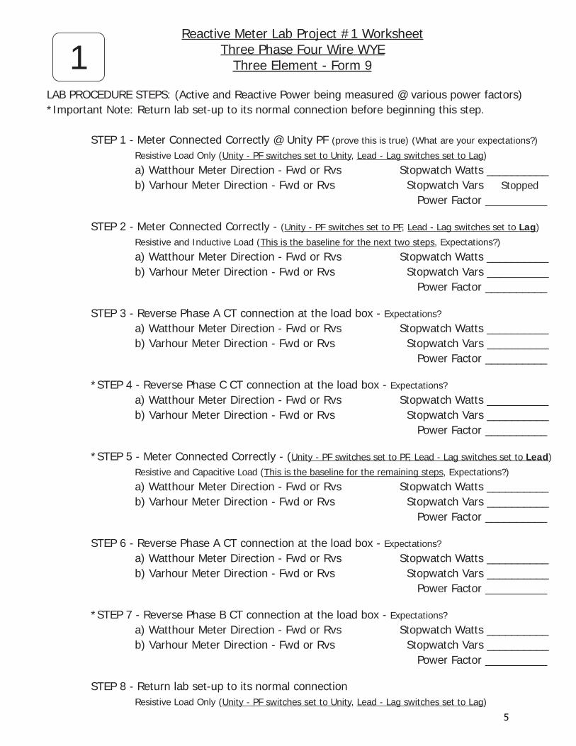
Reactive Meter Lab Project #1 WorksheetThree Phase Four Wire WYE
Three Element - Form 9
LAB PROCEDURE STEPS: (Active and Reactive Power being measured @ various power factors)*Important Note: Return lab set-up to its normal connection before beginning this step.
STEP 1 - Meter Connected Correctly @ Unity PF (prove this is true) (What are your expectations?)
Resistive Load Only (Unity - PF switches set to Unity, Lead - Lag switches set to Lag)
a) Watthour Meter Direction - Fwd or Rvs Stopwatch Watts __________ b) Varhour Meter Direction - Fwd or Rvs Stopwatch Vars Stopped Power Factor __________
STEP 2 - Meter Connected Correctly - (Unity - PF switches set to PF, Lead - Lag switches set to Lag)
Resistive and Inductive Load (This is the baseline for the next two steps, Expectations?)
a) Watthour Meter Direction - Fwd or Rvs Stopwatch Watts __________ b) Varhour Meter Direction - Fwd or Rvs Stopwatch Vars __________ Power Factor __________
STEP 3 - Reverse Phase A CT connection at the load box - Expectations?
a) Watthour Meter Direction - Fwd or Rvs Stopwatch Watts __________ b) Varhour Meter Direction - Fwd or Rvs Stopwatch Vars __________ Power Factor __________
*STEP 4 - Reverse Phase C CT connection at the load box - Expectations?
a) Watthour Meter Direction - Fwd or Rvs Stopwatch Watts __________ b) Varhour Meter Direction - Fwd or Rvs Stopwatch Vars __________ Power Factor __________
*STEP 5 - Meter Connected Correctly - (Unity - PF switches set to PF, Lead - Lag switches set to Lead)
Resistive and Capacitive Load (This is the baseline for the remaining steps, Expectations?)
a) Watthour Meter Direction - Fwd or Rvs Stopwatch Watts __________ b) Varhour Meter Direction - Fwd or Rvs Stopwatch Vars __________ Power Factor __________
STEP 6 - Reverse Phase A CT connection at the load box - Expectations?
a) Watthour Meter Direction - Fwd or Rvs Stopwatch Watts __________ b) Varhour Meter Direction - Fwd or Rvs Stopwatch Vars __________ Power Factor __________
*STEP 7 - Reverse Phase B CT connection at the load box - Expectations?
a) Watthour Meter Direction - Fwd or Rvs Stopwatch Watts __________ b) Varhour Meter Direction - Fwd or Rvs Stopwatch Vars __________ Power Factor __________
STEP 8 - Return lab set-up to its normal connection Resistive Load Only (Unity - PF switches set to Unity, Lead - Lag switches set to Lag)
1
5

Lab Project #2Three Phase Four Wire DELTATwo Element - Form 8
23-Phase 4 Wire DELTA - Form 8 Watthour Meter ABC Phase Sequence - Unity PF - Balanced 3 Phase Load
3-Phase 4 Wire DELTA - Form 8 Var-hour Meter ABC Phase Sequence - Unity PF - Balanced 3 Phase Load
Reference Vector Diagrams for Step 1 and 8
V - 8'9(Shifted, c'n)
Element #2
V - 4'5(Shifted, a'b)
Element #1
Ic
Ia(-Ib)
3-Phase 4 Wire DELTA - Form 8 Var-hour Meter ABC Phase Sequence - 60˚ Lagging PF - Balanced 3 Phase Load
3-Phase 4 Wire DELTA - Form 8 Watthour Meter ABC Phase Sequence - 60˚ Lagging PF - Balanced 3 Phase Load
Reference Vector Diagrams for Steps 2, 3, and 4
Element #1
Ic
V - c'n
Element #2
V - a'b
Ia(-Ib)
V - 8'9(Shifted, c'n)
Element #2
V - 4'5(Shifted, a'b)
Element #1
Ic
Ia(-Ib)
3-Phase 4 Wire DELTA - Form 8 Var-hour Meter ABC Phase Sequence - 60˚ Leading PF - Balanced 3 Phase Load
3-Phase 4 Wire DELTA - Form 8 Watthour Meter ABC Phase Sequence - 60˚ Leading PF - Balanced 3 Phase Load
Reference Vector Diagrams for Steps 5, 6, and 7
Element #1Ic
V - c'n
Element #2
V - a'b
Ia(-Ib)V - 8'9(Shifted, c'n)
Element #2
V - 4'5(Shifted, a'b)
Element #1
IcIa(-Ib)
Ic
V - c'n
Element #2
V - a'b
Element #1½(Ia)
½(-Ib)
.866 [Ia+(-Ib)]

Reactive Meter Lab Project #2 WorksheetThree Phase Four Wire DELTA
Two Element - Form 8
LAB PROCEDURE STEPS: (Active and Reactive Power being measured @ various power factors)*Important Note: Return lab set-up to its normal connection before beginning this step.
STEP 1 - Meter Connected Correctly @ Unity PF (prove this is true) (What are your expectations?)
Resistive Load Only (Unity - PF switches set to Unity, Lead - Lag switches set to Lag)
a) Watthour Meter Direction - Fwd or Rvs Stopwatch Watts __________ b) Varhour Meter Direction - Fwd or Rvs Stopwatch Vars Stopped Power Factor __________
STEP 2 - Meter Connected Correctly - (Unity - PF switches set to PF, Lead - Lag switches set to Lag)
Resistive and Inductive Load (This is the baseline for the next two steps, Expectations?)
a) Watthour Meter Direction - Fwd or Rvs Stopwatch Watts __________ b) Varhour Meter Direction - Fwd or Rvs Stopwatch Vars __________ Power Factor __________
STEP 3 - Reverse Phase A CT connection at the load box - Expectations?
a) Watthour Meter Direction - Fwd or Rvs Stopwatch Watts __________ b) Varhour Meter Direction - Fwd or Rvs Stopwatch Vars __________ Power Factor __________
*STEP 4 - Reverse Phase C CT connection at the load box - Expectations?
a) Watthour Meter Direction - Fwd or Rvs Stopwatch Watts __________ b) Varhour Meter Direction - Fwd or Rvs Stopwatch Vars __________ Power Factor __________
*STEP 5 - Meter Connected Correctly - (Unity - PF switches set to PF, Lead - Lag switches set to Lead)
Resistive and Capacitive Load (This is the baseline for the remaining steps, Expectations?)
a) Watthour Meter Direction - Fwd or Rvs Stopwatch Watts __________ b) Varhour Meter Direction - Fwd or Rvs Stopwatch Vars __________ Power Factor __________
STEP 6 - Reverse Phase A CT connection at the load box - Expectations?
a) Watthour Meter Direction - Fwd or Rvs Stopwatch Watts __________ b) Varhour Meter Direction - Fwd or Rvs Stopwatch Vars __________ Power Factor __________
*STEP 7 - Reverse Phase C CT connection at the load box - Expectations?
a) Watthour Meter Direction - Fwd or Rvs Stopwatch Watts __________ b) Varhour Meter Direction - Fwd or Rvs Stopwatch Vars __________ Power Factor __________
STEP 8 - Return lab set-up to its normal connection Resistive Load Only (Unity - PF switches set to Unity, Lead - Lag switches set to Lag)
2
7

Lab Project #3Three Phase Four Wire DELTATwo Element - Form 5(CTs have the same ratio and similar primary turns)
33-Phase 4 Wire DELTA - Form 5 Watthour Meter ABC Phase Sequence - Unity PF - Balanced 3 Phase Load
3-Phase 4 Wire DELTA - Form 5 Var-hour Meter ABC Phase Sequence - Unity PF - Balanced 3 Phase Load
Reference Vector Diagrams for Step 1 and 8
Element #1
Ic
V - c'n Element #2
V - a'bIa
(-Ib) Ia(-Ib)
V - 8'9(Shifted, c'n)
Element #2
V - 4'5(Shifted, a'b)
Element #1
Ic
Ia(-Ib)
3-Phase 4 Wire DELTA - Form 5 Var-hour Meter ABC Phase Sequence - 60˚ Lagging PF - Balanced 3 Phase Load
3-Phase 4 Wire DELTA - Form 5 Watthour Meter ABC Phase Sequence - 60˚ Lagging PF - Balanced 3 Phase Load
Reference Vector Diagrams for Steps 2, 3, and 4
Element #1
Ic
V - c'n
Element #2
V - a'b
Ia(-Ib)
V - 8'9(Shifted, c'n)
Element #2
V - 4'5(Shifted, a'b)
Element #1
Ic
Ia(-Ib)
3-Phase 4 Wire DELTA - Form 5 Var-hour Meter ABC Phase Sequence - 60˚ Leading PF - Balanced 3 Phase Load
3-Phase 4 Wire DELTA - Form 5 Watthour Meter ABC Phase Sequence - 60˚ Leading PF - Balanced 3 Phase Load
Reference Vector Diagrams for Steps 5, 6, and 7
Element #1Ic
V - c'n
Element #2
V - a'b
Ia(-Ib)V - 8'9(Shifted, c'n)
Element #2
V - 4'5(Shifted, a'b)
Element #1
IcIa(-Ib)
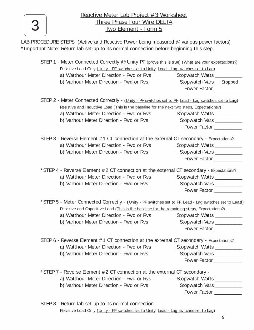
Reactive Meter Lab Project #3 WorksheetThree Phase Four Wire DELTA
Two Element - Form 5
LAB PROCEDURE STEPS: (Active and Reactive Power being measured @ various power factors)*Important Note: Return lab set-up to its normal connection before beginning this step.
STEP 1 - Meter Connected Correctly @ Unity PF (prove this is true) (What are your expectations?)
Resistive Load Only (Unity - PF switches set to Unity, Lead - Lag switches set to Lag)
a) Watthour Meter Direction - Fwd or Rvs Stopwatch Watts __________ b) Varhour Meter Direction - Fwd or Rvs Stopwatch Vars Stopped Power Factor __________
STEP 2 - Meter Connected Correctly - (Unity - PF switches set to PF, Lead - Lag switches set to Lag)
Resistive and Inductive Load (This is the baseline for the next two steps, Expectations?)
a) Watthour Meter Direction - Fwd or Rvs Stopwatch Watts __________ b) Varhour Meter Direction - Fwd or Rvs Stopwatch Vars __________ Power Factor __________
STEP 3 - Reverse Element #1 CT connection at the external CT secondary - Expectations?
a) Watthour Meter Direction - Fwd or Rvs Stopwatch Watts __________ b) Varhour Meter Direction - Fwd or Rvs Stopwatch Vars __________ Power Factor __________
*STEP 4 - Reverse Element #2 CT connection at the external CT secondary - Expectations?
a) Watthour Meter Direction - Fwd or Rvs Stopwatch Watts __________ b) Varhour Meter Direction - Fwd or Rvs Stopwatch Vars __________ Power Factor __________
*STEP 5 - Meter Connected Correctly - (Unity - PF switches set to PF, Lead - Lag switches set to Lead)
Resistive and Capacitive Load (This is the baseline for the remaining steps, Expectations?)
a) Watthour Meter Direction - Fwd or Rvs Stopwatch Watts __________ b) Varhour Meter Direction - Fwd or Rvs Stopwatch Vars __________ Power Factor __________
STEP 6 - Reverse Element #1 CT connection at the external CT secondary - Expectations?
a) Watthour Meter Direction - Fwd or Rvs Stopwatch Watts __________ b) Varhour Meter Direction - Fwd or Rvs Stopwatch Vars __________ Power Factor __________
*STEP 7 - Reverse Element #2 CT connection at the external CT secondary - a) Watthour Meter Direction - Fwd or Rvs Stopwatch Watts __________ b) Varhour Meter Direction - Fwd or Rvs Stopwatch Vars __________ Power Factor __________
STEP 8 - Return lab set-up to its normal connection Resistive Load Only (Unity - PF switches set to Unity, Lead - Lag switches set to Lag)
3
9
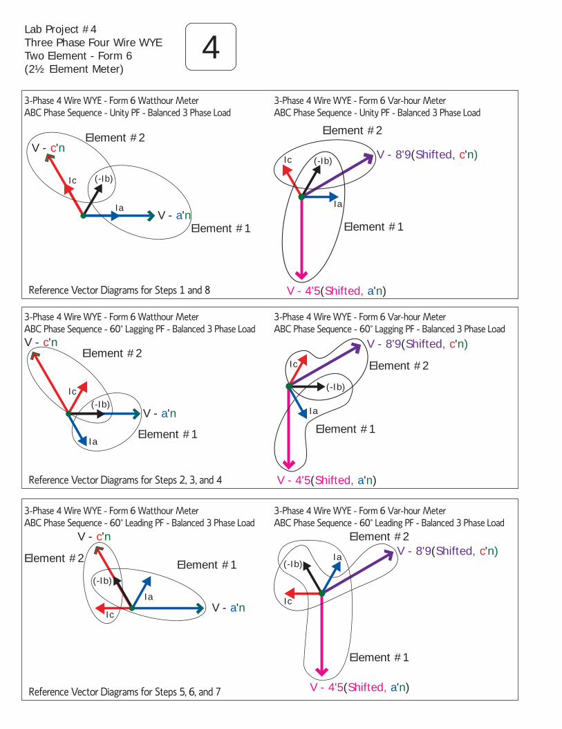
Lab Project #4Three Phase Four Wire WYETwo Element - Form 6(2½ Element Meter)
43-Phase 4 Wire WYE - Form 6 Watthour Meter ABC Phase Sequence - Unity PF - Balanced 3 Phase Load
3-Phase 4 Wire WYE - Form 6 Var-hour Meter ABC Phase Sequence - Unity PF - Balanced 3 Phase Load
Reference Vector Diagrams for Steps 1 and 8
Element #1
Element #2
V - 4'5(Shifted, a'n)
V - 8'9(Shifted, c'n)
Ia
(-Ib)Ic
3-Phase 4 Wire WYE - Form 6 Var-hour Meter ABC Phase Sequence - 60˚ Lagging PF - Balanced 3 Phase Load
3-Phase 4 Wire WYE - Form 6 Watthour Meter ABC Phase Sequence - 60˚ Lagging PF - Balanced 3 Phase Load
Reference Vector Diagrams for Steps 2, 3, and 4
Element #1
Element #2
V - 4'5(Shifted, a'n)
V - 8'9(Shifted, c'n)
Ia
Ic
(-Ib)
3-Phase 4 Wire WYE - Form 6 Var-hour Meter ABC Phase Sequence - 60˚ Leading PF - Balanced 3 Phase Load
3-Phase 4 Wire WYE - Form 6 Watthour Meter ABC Phase Sequence - 60˚ Leading PF - Balanced 3 Phase Load
Reference Vector Diagrams for Steps 5, 6, and 7
Element #1
Element #2
V - 4'5(Shifted, a'n)
V - 8'9(Shifted, c'n)Ia
Ic
(-Ib)
Element #1
V - c'n
V - a'n
Ic
Element #2
Ia
(-Ib)
Element #1
V - c'n
V - a'n(-Ib)
Element #2
Ia
Ic
Element #1
V - c'n
V - a'n
Element #2
Ia
Ic
(-Ib)

Reactive Meter Lab Project #4 WorksheetThree Phase Four Wire WYE
Two Element (2½ element) - Form 6
LAB PROCEDURE STEPS: (Active and Reactive Power being measured @ various power factors)*Important Note: Return lab set-up to its normal connection before beginning this step.
STEP 1 - Meter Connected Correctly @ Unity PF (prove this is true) (What are your expectations?)
Resistive Load Only (Unity - PF switches set to Unity, Lead - Lag switches set to Lag)
a) Watthour Meter Direction - Fwd or Rvs Stopwatch Watts __________ b) Varhour Meter Direction - Fwd or Rvs Stopwatch Vars Stopped Power Factor __________
STEP 2 - Meter Connected Correctly - (Unity - PF switches set to PF, Lead - Lag switches set to Lag)
Resistive and Inductive Load (This is the baseline for the next two steps, Expectations?)
a) Watthour Meter Direction - Fwd or Rvs Stopwatch Watts __________ b) Varhour Meter Direction - Fwd or Rvs Stopwatch Vars __________ Power Factor __________
STEP 3 - Reverse Phase A CT connection at the load box - Expectations?
a) Watthour Meter Direction - Fwd or Rvs Stopwatch Watts __________ b) Varhour Meter Direction - Fwd or Rvs Stopwatch Vars __________ Power Factor __________
*STEP 4 - Reverse Phase C CT connection at the load box - Expectations?
a) Watthour Meter Direction - Fwd or Rvs Stopwatch Watts __________ b) Varhour Meter Direction - Fwd or Rvs Stopwatch Vars __________ Power Factor __________
*STEP 5 - Meter Connected Correctly - (Unity - PF switches set to PF, Lead - Lag switches set to Lead)
Resistive and Capacitive Load (This is the baseline for the remaining steps, Expectations?)
a) Watthour Meter Direction - Fwd or Rvs Stopwatch Watts __________ b) Varhour Meter Direction - Fwd or Rvs Stopwatch Vars __________ Power Factor __________
STEP 6 - Reverse Phase A CT connection at the load box - Expectations?
a) Watthour Meter Direction - Fwd or Rvs Stopwatch Watts __________ b) Varhour Meter Direction - Fwd or Rvs Stopwatch Vars __________ Power Factor __________
*STEP 7 - Reverse Phase C CT connection at the load box - Expectations?
a) Watthour Meter Direction - Fwd or Rvs Stopwatch Watts __________ b) Varhour Meter Direction - Fwd or Rvs Stopwatch Vars __________ Power Factor __________
STEP 8 - Return lab set-up to its normal connection Resistive Load Only (Unity - PF switches set to Unity, Lead - Lag switches set to Lag)
4
11

Lab Project #5Three Phase Four Wire WYETwo Element - Form 5(Delta Connected CTs atthe Test Switch)
53-Phase 4 Wire WYE - Form 5 Watthour Meter ABC Phase Sequence - Unity PF - Balanced 3 Phase Load
3-Phase 4 Wire WYE - Form 5 Var-hour Meter ABC Phase Sequence - Unity PF - Balanced 3 Phase Load
Reference Vector Diagrams for Steps 1 and 8
Element #1
V - c'n
V - a'n
Ic
Element #2
Ia
(-Ib)Iab
Icb
Element #1
Element #2
V - 4'5(Shifted, a'n)
V - 8'9(Shifted, c'n)
Ia
(-Ib)
Iab
Icb
Ic
3-Phase 4 Wire WYE - Form 5 Var-hour Meter ABC Phase Sequence - 60˚ Lagging PF - Balanced 3 Phase Load
3-Phase 4 Wire WYE - Form 5 Watthour Meter ABC Phase Sequence - 60˚ Lagging PF - Balanced 3 Phase Load
Reference Vector Diagrams for Steps 2, 3, and 4
Element #1
V - c'n
V - a'n(-Ib)
Element #2
Ia
Ic Icb
Iab Element #1
Element #2
V - 4'5(Shifted, a'n)
V - 8'9(Shifted, c'n)
Ia
Ic Icb
Iab
(-Ib)
3-Phase 4 Wire WYE - Form 5 Var-hour Meter ABC Phase Sequence - 60˚ Leading PF - Balanced 3 Phase Load
3-Phase 4 Wire WYE - Form 5 Watthour Meter ABC Phase Sequence - 60˚ Leading PF - Balanced 3 Phase Load
Reference Vector Diagrams for Steps 5, 6, and 7
Element #1
V - c'n
V - a'n
Element #2
Ia
Ic
(-Ib)Icb
Iab
Element #1
Element #2
V - 4'5(Shifted, a'n)
V - 8'9(Shifted, c'n)Ia
Ic
(-Ib)Icb
Iab

Reactive Meter Lab Project #5 WorksheetThree Phase Four Wire WYE
Two Element - Form 5 - Delta Connected CTs
LAB PROCEDURE STEPS: (Active and Reactive Power being measured @ various power factors)*Important Note: Return lab set-up to its normal connection before beginning this step.
STEP 1 - Meter Connected Correctly @ Unity PF (prove this is true) (What are your expectations?)
Resistive Load Only (Unity - PF switches set to Unity, Lead - Lag switches set to Lag)
a) Watthour Meter Direction - Fwd or Rvs Stopwatch Watts __________ b) Varhour Meter Direction - Fwd or Rvs Stopwatch Vars Stopped Power Factor __________
STEP 2 - Meter Connected Correctly - (Unity - PF switches set to PF, Lead - Lag switches set to Lag)
Resistive and Inductive Load (This is the baseline for the next two steps, Expectations?)
a) Watthour Meter Direction - Fwd or Rvs Stopwatch Watts __________ b) Varhour Meter Direction - Fwd or Rvs Stopwatch Vars __________ Power Factor __________
STEP 3 - Reverse Phase A CT connection at the load box - Expectations?
a) Watthour Meter Direction - Fwd or Rvs Stopwatch Watts __________ b) Varhour Meter Direction - Fwd or Rvs Stopwatch Vars __________ Power Factor __________
*STEP 4 - Reverse Phase C CT connection at the load box - Expectations?
a) Watthour Meter Direction - Fwd or Rvs Stopwatch Watts __________ b) Varhour Meter Direction - Fwd or Rvs Stopwatch Vars __________ Power Factor __________
*STEP 5 - Meter Connected Correctly - (Unity - PF switches set to PF, Lead - Lag switches set to Lead)
Resistive and Capacitive Load (This is the baseline for the remaining steps, Expectations?)
a) Watthour Meter Direction - Fwd or Rvs Stopwatch Watts __________ b) Varhour Meter Direction - Fwd or Rvs Stopwatch Vars __________ Power Factor __________
STEP 6 - Reverse Phase A CT connection at the load box - Expectations?
a) Watthour Meter Direction - Fwd or Rvs Stopwatch Watts __________ b) Varhour Meter Direction - Fwd or Rvs Stopwatch Vars __________ Power Factor __________
*STEP 7 - Reverse Phase C CT connection at the load box - Expectations?
a) Watthour Meter Direction - Fwd or Rvs Stopwatch Watts __________ b) Varhour Meter Direction - Fwd or Rvs Stopwatch Vars __________ Power Factor __________
STEP 8 - Return lab set-up to its normal connection Resistive Load Only (Unity - PF switches set to Unity, Lead - Lag switches set to Lag)
5
13
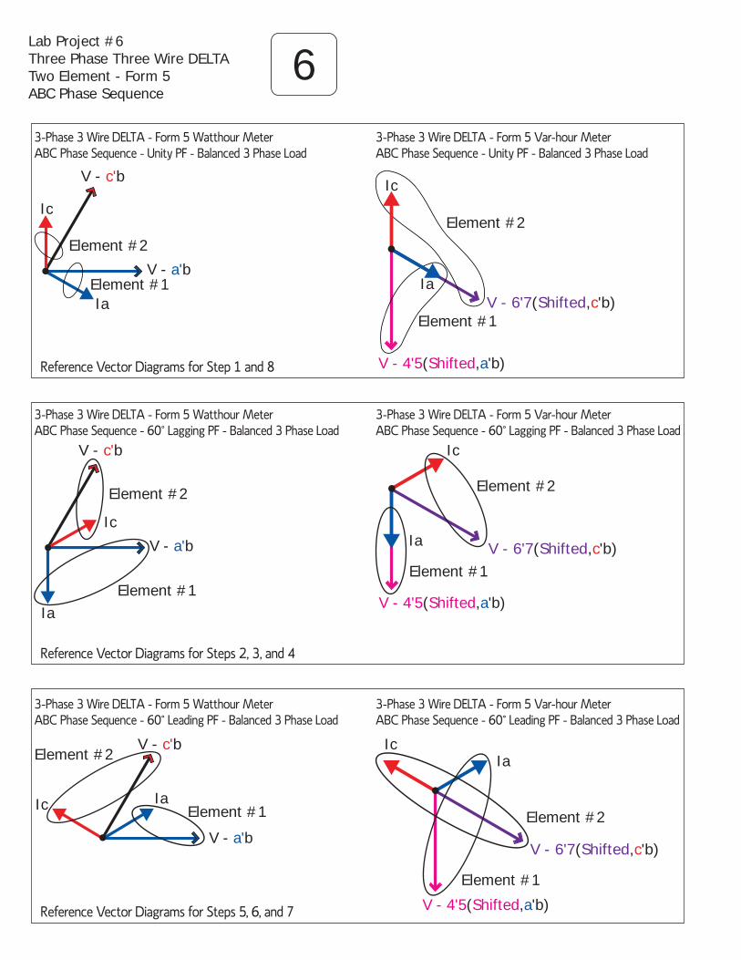
6Lab Project #6Three Phase Three Wire DELTATwo Element - Form 5ABC Phase Sequence
3-Phase 3 Wire DELTA - Form 5 Watthour Meter ABC Phase Sequence - Unity PF - Balanced 3 Phase Load
3-Phase 3 Wire DELTA - Form 5 Var-hour Meter ABC Phase Sequence - Unity PF - Balanced 3 Phase Load
3-Phase 3 Wire DELTA - Form 5 Var-hour Meter ABC Phase Sequence - 60˚ Lagging PF - Balanced 3 Phase Load
Ic
V - 6'7(Shifted,c'b)
Element #2
V - 4'5(Shifted,a'b)
Element #1
Ia
3-Phase 3 Wire DELTA - Form 5 Var-hour Meter ABC Phase Sequence - 60˚ Leading PF - Balanced 3 Phase Load
Ic
V - 6'7(Shifted,c'b)
Element #2
V - 4'5(Shifted,a'b)
Element #1
Ia
3-Phase 3 Wire DELTA - Form 5 Watthour Meter ABC Phase Sequence - 60˚ Lagging PF - Balanced 3 Phase Load
3-Phase 3 Wire DELTA - Form 5 Watthour Meter ABC Phase Sequence - 60˚ Leading PF - Balanced 3 Phase Load
Ia
Ic
V - c'b
Element #2
V - a'bElement #1
Ic
V - c'b
Element #2
V - a'b
Element #1Ia
Ic
V - c'bElement #2
V - a'b
Element #1Ia
Ic
V - 6'7(Shifted,c'b)
Element #2
V - 4'5(Shifted,a'b)
Element #1
Ia
Reference Vector Diagrams for Step 1 and 8
Reference Vector Diagrams for Steps 2, 3, and 4
Reference Vector Diagrams for Steps 5, 6, and 7

Reactive Meter Lab Project #6 WorksheetThree Phase Three Wire DELTA - ABC Phase Sequence
Two Element - Form 5
LAB PROCEDURE STEPS: (Active and Reactive Power being measured @ various power factors)*Important Note: Return lab set-up to its normal connection before beginning this step.
STEP 1 - Meter Connected Correctly @ Unity PF (prove this is true) (What are your expectations?)
Resistive Load Only (Unity - PF switches set to Unity, Lead - Lag switches set to Lag)
a) Watthour Meter Direction - Fwd or Rvs Stopwatch Watts __________ b) Varhour Meter Direction - Fwd or Rvs Stopwatch Vars Stopped Power Factor __________
STEP 2 - Meter Connected Correctly - (Unity - PF switches set to PF, Lead - Lag switches set to Lag)
Resistive and Inductive Load (This is the baseline for the next two steps, Expectations?)
a) Watthour Meter Direction - Fwd or Rvs Stopwatch Watts __________ b) Varhour Meter Direction - Fwd or Rvs Stopwatch Vars __________ Power Factor __________
STEP 3 - Reverse Phase A CT connection at the load box - Expectations?
a) Watthour Meter Direction - Fwd or Rvs Stopwatch Watts __________ b) Varhour Meter Direction - Fwd or Rvs Stopwatch Vars __________ Power Factor __________
*STEP 4 - Reverse Phase C CT connection at the load box - Expectations?
a) Watthour Meter Direction - Fwd or Rvs Stopwatch Watts __________ b) Varhour Meter Direction - Fwd or Rvs Stopwatch Vars __________ Power Factor __________
*STEP 5 - Meter Connected Correctly - (Unity - PF switches set to PF, Lead - Lag switches set to Lead)
Resistive and Capacitive Load (This is the baseline for the remaining steps, Expectations?)
a) Watthour Meter Direction - Fwd or Rvs Stopwatch Watts __________ b) Varhour Meter Direction - Fwd or Rvs Stopwatch Vars __________ Power Factor __________
STEP 6 - Reverse Phase A CT connection at the load box - Expectations?
a) Watthour Meter Direction - Fwd or Rvs Stopwatch Watts __________ b) Varhour Meter Direction - Fwd or Rvs Stopwatch Vars __________ Power Factor __________
*STEP 7 - Reverse Phase C CT connection at the load box - Expectations?
a) Watthour Meter Direction - Fwd or Rvs Stopwatch Watts __________ b) Varhour Meter Direction - Fwd or Rvs Stopwatch Vars __________ Power Factor __________
STEP 8 - Return lab set-up to its normal connection
Resistive Load Only (Unity - PF switcheses set to Unity, Lead - Lag switcheses set to Lag)
6
15

7Lab Project #7Three Phase Three Wire DELTATwo Element - Form 5CBA Phase Sequence
3-Phase 3 Wire DELTA - Form 5 Watthour Meter CBA Phase Sequence - Unity PF - Balanced 3 Phase Load
3-Phase 3 Wire DELTA - Form 5 Var-hour Meter CBA Phase Sequence - Unity PF - Balanced 3 Phase Load
3-Phase 3 Wire DELTA - Form 5 Var-hour Meter CBA Phase Sequence - 60˚ Lagging PF - Balanced 3 Phase Load
3-Phase 3 Wire DELTA - Form 5 Watthour Meter CBA Phase Sequence - 60˚ Lagging PF - Balanced 3 Phase Load
Ia
Ic
V - c'b
Element #2
V - a'bElement #1
Reference Vector Diagrams for Steps 1 and 8
Reference Vector Diagrams for Steps 2, 3, and 4
Reference Vector Diagrams for Steps 5, 6, and 7
IaIc
V - c'b
Element #2
V - a'b
Element #1
3-Phase 3 Wire DELTA - Form 5 Watthour Meter CBA Phase Sequence - 60˚ Leading PF - Balanced 3 Phase Load
Ia
Ic
V - c'b
Element #2
V - a'b
Element #1
Ia
Ic
V - 6'7 (Shifted,c'b)
Element #2
V - 4'5 (Shifted,a'b)
Element #1
3-Phase 3 Wire DELTA - Form 5 Var-hour Meter CBA Phase Sequence - 60˚ Leading PF - Balanced 3 Phase Load
Ia
Ic
V - 6'7 (Shifted,c'b)
Element #2
V - 4'5 (Shifted,a'b)
Element #1
IaIc
V - 6'7 (Shifted,c'b)
Element #2
V - 4'5 (Shifted,a'b)
Element #1

Reactive Meter Lab Project #7 WorksheetThree Phase Three Wire DELTA - CBA Phase Sequence
Two Element - Form 5
LAB PROCEDURE STEPS: (Active and Reactive Power being measured @ various power factors)*Important Note: Return lab set-up to its normal connection before beginning this step.
STEP 1 - Meter Connected Correctly @ Unity PF (prove this is true) (What are your expectations?)
Resistive Load Only (Unity - PF switches set to Unity, Lead - Lag switches set to Lag)
a) Watthour Meter Direction - Fwd or Rvs Stopwatch Watts __________ b) Varhour Meter Direction - Fwd or Rvs Stopwatch Vars Stopped Power Factor __________
STEP 2 - Meter Connected Correctly - (Unity - PF switches set to PF, Lead - Lag switches set to Lag)
Resistive and Inductive Load (This is the baseline for the next two steps, Expectations?)
a) Watthour Meter Direction - Fwd or Rvs Stopwatch Watts __________ b) Varhour Meter Direction - Fwd or Rvs Stopwatch Vars __________ Power Factor __________
STEP 3 - Reverse Phase A CT connection at the load box - Expectations?
a) Watthour Meter Direction - Fwd or Rvs Stopwatch Watts __________ b) Varhour Meter Direction - Fwd or Rvs Stopwatch Vars __________ Power Factor __________
*STEP 4 - Reverse Phase C CT connection at the load box - Expectations?
a) Watthour Meter Direction - Fwd or Rvs Stopwatch Watts __________ b) Varhour Meter Direction - Fwd or Rvs Stopwatch Vars __________ Power Factor __________
*STEP 5 - Meter Connected Correctly - (Unity - PF switches set to PF, Lead - Lag switches set to Lead)
Resistive and Capacitive Load (This is the baseline for the remaining steps, Expectations?)
a) Watthour Meter Direction - Fwd or Rvs Stopwatch Watts __________ b) Varhour Meter Direction - Fwd or Rvs Stopwatch Vars __________ Power Factor __________
STEP 6 - Reverse Phase A CT connection at the load box - Expectations?
a) Watthour Meter Direction - Fwd or Rvs Stopwatch Watts __________ b) Varhour Meter Direction - Fwd or Rvs Stopwatch Vars __________ Power Factor __________
*STEP 7 - Reverse Phase C CT connection at the load box - Expectations?
a) Watthour Meter Direction - Fwd or Rvs Stopwatch Watts __________ b) Varhour Meter Direction - Fwd or Rvs Stopwatch Vars __________ Power Factor __________
STEP 8 - Return lab set-up to its normal connection
Resistive Load Only (Unity - PF switches set to Unity, Lead - Lag switches set to Lag)
7
17

V A’NV N’A
V N’C
V C’N
V B’N
V N’B V A’B
V C’B
V C’A
V B’C
V B’A V A’C
Reference Three Phase Voltage VectorsPhase to Neutral and Phase to Phase Voltages (by polarity)

RIGHT TRIANGLE RELATIONSHIPSfor Electrical Power
Watts (W)
Vars (Vr)Volt Amps (V
a)
θ
Trigonometric Functions for a Power TriangleFormula 1 Sine of Angle θ = Vars Volt Amps
Formula 4 Volt Amps x Sine of Angle θ = Vars
Formula 7Volt Amps = Vars Sine of Angle θ
Formula 2 Cosine of Angle θ = Watts Volt Amps
Formula 5Volt Amps x Cosine of Angle θ = Watts
Formula 8Volt Amps = Watts Cosine of Angle θ
Formula 3 Tangent of Angle θ = Vars Watts
Formula 6Watts x Tangent of Angle θ = Vars
Formula 9Watts = Vars Tangent of Angle θ
Pythagorean Theorem Formulas for a Power Triangle
Formula 10 - Volt Amps = Watts2 + Vars2
Formula 11- Watts = Volt Amps2 - Vars2
Formula 12 - Vars = Volt Amps2 - Watts2
Related Information on Power Factor and Phase Angles
Power Factor for the Circuit = Cosine of Angle θ or Watts or Active Power Volt Amps Apparent Power
The degree value of Angle θ = Inverse of the Tangent of Angle θ or Vars (Arc tangent or TAN-1) = Phase Angle θ Watts
Additionally, the degree value of Angle θ also equals the inverse of the Sine of Angle θ or the inverse of the Cosine of Angle θ
Volt Amps = Apparent Power
Watts = Active Power
Vars = Reactive Power
19