reaction tuning of selectively deposited nano-thermite
TRANSCRIPT

Purdue UniversityPurdue e-Pubs
Open Access Theses Theses and Dissertations
12-2016
Reaction tuning of selectively deposited nano-thermite inks for thrust and heat depositionRaghav RamachandranPurdue University
Follow this and additional works at: https://docs.lib.purdue.edu/open_access_theses
Part of the Mechanical Engineering Commons
This document has been made available through Purdue e-Pubs, a service of the Purdue University Libraries. Please contact [email protected] foradditional information.
Recommended CitationRamachandran, Raghav, "Reaction tuning of selectively deposited nano-thermite inks for thrust and heat deposition" (2016). OpenAccess Theses. 888.https://docs.lib.purdue.edu/open_access_theses/888

Graduate School Form
30 Updated
PURDUE UNIVERSITY
GRADUATE SCHOOL
Thesis/Dissertation Acceptance
This is to certify that the thesis/dissertation prepared
By
Entitled
For the degree of
Is approved by the final examining committee:
To the best of my knowledge and as understood by the student in the Thesis/Dissertation
Agreement, Publication Delay, and Certification Disclaimer (Graduate School Form 32),
this thesis/dissertation adheres to the provisions of Purdue University’s “Policy of
Integrity in Research” and the use of copyright material.
Approved by Major Professor(s):
Approved by:
Head of the Departmental Graduate Program Date
Raghav Ramachandran
Reaction Tuning of Selectively Deposited Nano-thermite Inks for Thrust and Heat Deposition
Master of Science in Mechanical Engineering
Steven F. Son
Chair
Ibrahim E. Gunduz
Co-chair
Jeffrey F. Rhoads
Co-chair
Steven F. Son
Jay P. Gore 12/1/2016


REACTION TUNING OF SELECTIVELY DEPOSITED NANO-THERMITE INKS
FOR THRUST AND HEAT DEPOSITION
A Thesis
Submitted to the Faculty
of
Purdue University
by
Raghav Ramachandran
In Partial Fulfillment of the
Requirements for the Degree
of
Master of Science in Mechanical Engineering
December 2016
Purdue University
West Lafayette, Indiana

ii
ACKNOWLEDGEMENTS
I want to express my sincere gratitude to Professor Steven Son for allowing me to join his
research group and giving me the opportunity to work on several cutting edge projects as
well as providing me with his support and guidance. I would also like to thank Professor
Emre Gunduz for his guidance with my experimental setups and helpful discussions.
Many thanks to Vasant Vuppuluri, Trevor Fleck, Gabriel Diez, and Eric Westphal, who
at some point or other have aided me in safely handling all of the nano-thermite batches
and helped with my experiments. A special thanks goes to Professor Jeffrey Rhoads for
his leadership on this project, as well as for serving on my committee. I would also like
to acknowledge Dr. Cathie Condron for funding this project through the Defense Threat
Reduction Agency grant no. HDTRA 1-15-1-0010.

iii
TABLE OF CONTENTS
Page
LIST OF TABLES ............................................................................................................. iv
LIST OF FIGURES .............................................................................................................v
ABSTRACT ....................................................................................................................... vi
CHAPTER 1. INTRODUCTION ........................................................................................1
1.1 Nano-aluminum and Nano-thermite combustion....................................................1
1.2 Integration of Nano-Energetics with MEMS ..........................................................5
1.3 Motivation ...............................................................................................................9
CHAPTER 2. EXPERIMENTAL METHODS .................................................................10
2.1 Sample Preparation ...............................................................................................10
2.2 Thrust Measurements ............................................................................................12
2.3 Thermal Measurements .........................................................................................13
CHAPTER 3. RESULTS AND DISCUSSION .................................................................15
3.1 Thermochemical Equilibrium Calculations ..........................................................15
3.2 Thrust Measurement Results.................................................................................16
3.3 Thermal Measurement Results .............................................................................21
CHAPTER 4. CONCLUSIONS AND FUTURE WORK .................................................25
LIST OF REFERENCES ...................................................................................................27
APPENDICES
APPENDIX A: NANO-THERMITE MIXING PROCEDURE ........................................31
APPENDIX B: SAMPLE MIXING SHEET .....................................................................34

iv
LIST OF TABLES
Table Page
1.1 Nano-thermite performance summary. .......................................................................7
v
LIST OF FIGURES
Figure Page
1.1 Schematic of a semi-conductor bridge. ....................................................................5
1.2 Combustion chamber without and with converging-diverging nozzle. ...................6
1.3 Micro-machined thruster. .........................................................................................7
1.4 Schematic of microelectronic thruster incorporating nano-thermite. ......................8
2.1 Fixture and syringe for resonant mixing of nano-thermites. ..................................10
2.2 Image of deposited nano-thermite which has been dried. ......................................11
2.3 Thrust measurement schematic. .............................................................................12
2.4 Thermal measurement schematic. ..........................................................................13
2.5 Region of interest used to average temperature of wafer. ....................................14
3.1 Predicted performance of Al-CuO. ........................................................................16
3.2 Predicted performance of Al-Bi2O3. ......................................................................16
3.3 Summary of thrust performance of Al-CuO. .........................................................19
3.4 Summary of thrust performance of Al-Bi2O3. .......................................................19
3.5 Typical force traces for Al-CuO. ...........................................................................20
3.6 Typical force traces for Al-Bi2O3. .........................................................................20
3.7 Schlieren imaging of stoichiometric Al-CuO. .......................................................20
3.8 Schlieren imaging of Al-CuO at very fuel-rich conditions (=8). .........................21
3.9 Schlieren imaging of stoichiometric Al-Bi2O3. .....................................................21
3.10 Schlieren imaging of Al-Bi2O3 at very fuel-rich conditions (=10). .....................21
3.11 A typical nAl temperature trace measured on the back side of a wafer. ...............23
3.12 Typical Al-CuO temperature traces. ......................................................................23
3.13 Typical Al-Bi2O3 temperature traces. ....................................................................23
3.14 Summary of heat deposition with Al-CuO samples. .............................................24
3.15 Summary of heat deposition with Al-Bi2O3 samples. ............................................24

vi
ABSTRACT
Ramachandran, Raghav. M.S.M.E., Purdue University, December 2016. Reaction Tuning
of Selective Nano-thermite Inks for Thrust and Heat Deposition. Major Professor: Steven
F. Son, School of Mechanical Engineering.
Currently, there is very little systematic work that quantifies the performance of
energetic materials in terms of thrust or heat deposition applied to electronic circuits. A
better understanding of the interactions between nano-scale energetic materials and
electronic systems, as a function of stoichiometry is needed for enhanced defeat. Both of
these needs are addressed in this research. Formulations of Al-CuO and Al-Bi2O3 nano-
thermites were prepared at different equivalence ratios and selectively deposited onto
silicon substrates and the thrust and heat deposition of these materials was quantified.
Both nano-thermite systems produced maximum thrust near stoichiometric ratios, and
more fuel-rich mixtures led to significant decreases in thrust. In contrast, fuel-rich
formulations of both nano-thermite systems resulted in increased heat deposition, due to
less gas production, which removed hot products from substrate surfaces, and lower heat
deposition was observed near stoichiometric ratios. The heat transfer from the Al-CuO
system increased more than the Al-Bi2O3 system at fuel rich conditions. The developed
methodology can be used to characterize and optimize other materials for possible
integration into electronic devices.

1
CHAPTER 1: INTRODUCTION
1.1 Nano-aluminum and Nano-thermite Combustion
In the field of energetic materials, monomolecular explosives are widely used. As
the fuel and oxidizer are already combined in a single molecule, breaking molecular
bonds results in a release of energy over a short timescale. The integration of most of
these materials in small geometric configurations is difficult, as their volumetric heats of
combustion are too low to successfully allow for propagation at the micro-scale [1]. In
addition, these materials may be difficult to ignite and quench immediately after ignition
within these geometries [2]. Metal fuels have been shown to have higher volumetric
combustion enthalpies and energy densities, which makes them an ideal candidate for use
in micro-scale energetics. Although boron has the highest known volumetric heat of
combustion when ignited in air, boron particle ignition delays are too large to be utilized
in energetic formulations [3].
Aluminum is a preferred fuel in blast explosives and propellants due to its wide
availability. Ignition characteristics of aluminum particles are highly dependent on
particle size. Particles with diameters greater than 100 m only ignite once the aluminum
oxide shell melts. However, nano-scale aluminum (less 100 nm in diameter) exhibits
rapid combustion at ignition temperatures closer to the melting point of aluminum [3].
As the particle diameter decreases, the specific surface area of the aluminum particles
increases. This allows for a higher reactivity at the particle surface, increasing the overall
reactivity [1]. All aluminum particles feature a 2-5 nm alumina shell on their surface.
For micron-scale particles, the effect of the oxide shell on particle mass can be neglected.
With nano-scale aluminum, the active aluminum content in nano-scale aluminum
particles needs to be accounted for since the alumina shell is considered to be inert [4].

2
A thermite reaction is an oxidation-reduction reaction consisting of a metal and a
metal-oxide behaving as a fuel and oxidizer, respectively. Traditionally, these reactions
were used in the formation of structural metals through their high temperature reactions,
as in the welding of railroad tracks [5]. Fischer and Grueblich have tabulated the
theoretical maximum density, adiabatic flame temperature, gas production, and heat of
combustion for a variety of thermite reactions [6]. Aluminum is a commonly used fuel in
these reactions. Thermites mixed with micron-scale constituents react through the
diffusion of particles. The mixing of nano-scale aluminum and nano-scale metal oxides
(<100 nm) results in the formation of so-called nano-thermites. The high interfacial
contact between the nanoparticles and the small diffusion scales enhance the chemical
kinetics between the fuel and oxidizer, allowing for high energy releases and rapid
pressurization upon ignition [7]. Nano-thermites have also been referred to as metastable
intermolecular composites, as the mixture stays in an inert form prior to ignition [8].
However, special care is needed when handling nano-thermites, as these materials are
very sensitive to impact, spark, and friction [2].
While there are advantages to other approaches of synthesizing nano-thermite
formulations, including self-assembly and ball-milling, physical mixing is the most
commonly used method to process large batches of nano-thermite [8]. As nano-thermites
are highly sensitive to electrostatic discharge, wet processing of the materials is highly
recommended. Pusynzki et al. demonstrated the ability to process nano-thermites in
water, if the nano-aluminum was well coated with hydrophilic materials like ammonium
dihydrogen phosphate or hydrophobic materials like oleic acid. While coating nano-
aluminum increased the resistivity of converting to aluminum oxide, full oxidation
occurred within 15 hours of mixing [9]. Otherwise, it is preferred that nano-scale
powders are typically mixed in an aprotic solvent to prevent the oxidation of nano-
aluminum [10].
Ultrasonic mixing has been a popular physical mixing technique for nano-
thermites [8]. This method is widely used to prepare powders, but it may pose some
problems for the development of inks for deposition. One major drawback is the larger

3
amounts of solvent needed to mix a suspension without inducing a combustion reaction
of the nanoparticles. With larger amounts of solvent in suspension, the phase separation
of particles occurs over time. In contrast, resonant mixing uses a low resonant frequency
to agitate a bulk mixture, which allows for the mixing of highly viscous suspensions [11].
Near stoichiometric conditions, the propagation of nano-thermites is driven by
advection. Rapid pressurization upon combustion allows for the thermal transport of
molten material to unreacted zones, leading to fast reactions. Experimental results also
confirm that maximum propagation speeds correlate with peak pressurization and low
densities [12]. Zachariah and Egan also contend that conduction and radiation are
negligible in experimental conditions used in previous propagation experiments, based on
physical properties of the “burn tubes” used in such experiments [13]. In contrast,
conductive heat transfer dominates the combustion of very fuel rich nano-thermite
systems [14] or nano-thermites prepared at high packing densities [12]. The inclusion of
binders has been another technique to tune the reactivity of nano-thermite mixtures. The
addition of fluoropolymer binders has reduced the peak pressurizations and increased the
ignition sensitivities of nano-thermites. Such binders are well utilized because of the
aluminum-fluorine reactions that occur [15].
Dutro et. al stated that there are three different types of propagations depending
on the equivalence ratio: steady propagation driven by advection, an unsteady
acceleration wave, and a steady slow propagation driven by conduction [14]. Similarly, a
wide range of propagation behaviors were seen through varying the addition of alumina
in nano-thermites as a diluent. Here, three distinct propagation regimes were observed: a
constant velocity regime, a constant acceleration regime, and an unsteady spiraling
combustion wave [16].
Several theories have been proposed regarding the chemical kinetics and reaction
mechanisms that control the combustion of nano-scale thermites. As the alumina layer
on nano-aluminum acts as a barrier to reaction, the ignition of nanothermites either
occurs through diffusion in the alumina layer or by breaking the oxide layer [13].
Therefore, the ignition of nano-thermites highly depends on heating rates. Nano-

4
thermites heated at “slower” heating rates exhibit reactions dominated by diffusion
processes, similar to micron-scale thermites. The melt-dispersion reaction mechanism is
proposed at higher heating rates (greater than 1E6 K/s). Here, the aluminum core melts
and leads to the fracture of the alumina shell, allowing for the dispersion of molten
aluminum [17].
Another theory postulates that gaseous oxygen may drive the ignition of nano-
thermites. Metal oxides decompose into a stable phase, releasing gaseous oxygen at high
temperatures. Rapid heating experiments were conducted to monitor temperatures at
which O2 is released. Only certain nano-thermite systems had similar ignition and O2
release temperatures, suggesting that other reaction mechanisms dominate nano-thermite
combustion [18].
Recent literature proposes that the nano-thermite reactions are strongly driven by
condensed phase reaction mechanisms [19-20]. Specifically, the sintering of aggregated
particles into bigger structures was observed with a variety of nano-thermite systems.
Similar to the melt dispersion mechanism, molten aluminum disperses and interacts with
the oxidizer, increasing the interfacial area and speeding reaction rates [19]. High-speed
imaging with nano-second temporal resolution showed that there were large interfaces
between the fuel and oxidizer, resulting in changes in particle morphology after ignition.
[20].
The two nano-thermite systems relevant to the experiments described herein are
aluminum-copper oxide (Al-CuO) and aluminum-bismuth trioxide (Al-Bi2O3). Both
nano-thermites prepared at stoichiometric conditions are known to be gas generators and
have been investigated in a variety of experiments. Al-CuO is expected to produce more
heat and less gas generation compared to Al-Bi2O3 [6]. Al-Bi2O3 is considered to be one
of the most reactive nano-thermite systems. Bismuth boils at temperatures beneath the
reaction temperature of Al-Bi2O3, and the evaporation of bismuth coincides with peak
pressurization. The evaporation of bismuth allows for more gas release, allowing for
more advective transport of reacted particles and therefore increasing the propagation
speeds [21].

5
1.2 Integration of Nano-Energetics with MEMS
The integration of energetic materials in electronic systems has been considered
for the past four decades. Anti-tamper devices integrated with aluminized pyrotechnic
formulations were developed in order to address critical needs for self-destruction within
electronics. One specific example cited describes the use of aluminum and tungsten
oxide thin films [22-23].
Likewise, semi-conductor bridge (SCB) technology was developed as an alternate
method for the initiation and ignition of explosive powders. A schematic can be seen in
Fig 1.1. SCBs have demonstrated operability with lower energy inputs and smaller
volumes of traditional bridge-wires on electro-explosive devices [24]. Experimental
work has been conducted to assess the possibilities of integrating nano-thermites with
SCB initiators [25].
Figure 1.1: Schematic of a semi-conductor bridge [24].
The possibilities for integrating energetic materials in microelectronic systems has
widely increased with the advancements in nanotechnology, resulting in the emergence of
the on-chip micro-energetics field [26-27]. Recent safe-and-arm devices utilize
miniaturized electromechanical components to arm and disarm pyrotechnic initiators in
munitions [28].
Another potential application is in the field of power generation. While nano-
energetic materials could potentially be used in microscale devices for energy harvesting
6
[26], nano-scale metal fuels could also be used in large scale applications. One example
postulates that if nano-aluminum is burned in suspension with air as the oxidizer, and the
metal oxide products could then be captured and reconverted into metal fuels using phase
separation technology [29].
The utilization of nano-energetics in micro-actuation and micro-propulsion
applications has been well documented. The combustion of energetic materials provides
the largest actuation pressures at the microscale in comparison to other types of actuation
[26-27]. An early example uses a thin film propellant heated with resistive wire onto a
silicon substrate [30]. Other examples integrate deposited energetic material onto
fabricated Joule-heating initiators [31].
There are many examples of energetic materials used in micro-propulsion
applications [27]. Nano-thermite formulations have also been considered in micro-
propulsion devices has been considered [21, 32-35]. In one early set of experiments, Al-
CuO powder was prepared ultrasonically and pressed into pellets of different densities
within combustion chambers as seen in Fig 1.2. Thrust measurements were measured
using a high impedance force sensor [32].
Figure 1.2: Combustion chamber without and with converging-diverging nozzle [32].
Results verified that high density thermites had lower thrusts than low density
thermites, as their propagation was driven by conduction over advection. Converging-
divergences had no effects on thrust for low density thermites, but the effect of
confinement increased thrust with high density thermites [32].

7
More recent experiments from the same research group described thrust
measurements performed with the experimental setup seen in Fig. 1.3. Both Al-CuO and
Al-Bi2O3 were prepared ultrasonically and pressed into low density thermites within a
chamber [32-33]. Initial experiments were done to validate that the optimal
stoichiometry of Al-Bi2O3 for maximum thrust were at slightly fuel rich conditions, even
with the inclusion of nitrocellulose as a binder [33].
Figure 1.3: Micro-machined thruster [33].
Table 1.1: Nano-thermite performance summary [34].
Nanothermite Average
thrust, N
Duration,
ms
Impulse,
mN*s
Isp, s Isv,
mN*s*mm-3
CuO/Al 4.6 ± 0.4 5.1 ± 0.5 23.0 ± 0.6 20.2 ± 1.3 0.5 ± 0.0
CuO/Al/NC
(2.5%)
2.7 ± 0.4 10.4 ± 0.4 28.3 ± 4.2 24.2 ± 3.8 0.6 ± 0.1
CuO/Al/NC
(5.0%)
0.8 ± 0.2 23.1 ± 3.6
19.5 ± 6.9 15.7 ± 4.3 0.4 ± 0.2
Bi2O3/Al 46.1 ± 2.6 1.7 ± 0.0 78.6 ± 4.8 41.4 ± 1.2 1.7 ± 0.1
Bi2O3/Al/NC
(2.5%)
22.4 ± 2.8 4.9 ± 0.4 108.8 ± 4.3 54.2 ± 1.7 2.3 ± 0.1
Bi2O3/Al/NC
(5.0%)
7.8 ± 1.6 13.7 ± 2.0 105.7 ± 3.9 59.4 ± 2.9 2.2 ± 0.1

8
The effects of incorporating binder for both nano-thermite systems at quantities
up to 5 weight percentage binder were also examined. The inclusions of binders into
nano-thermite mixtures were shown to decrease thrust and increase impulse due to their
longer reaction timescales. The results from these experiments can be seen in Table 1.1
[34].
Another paper discusses integrating nano-thermite directly into a fabricated
silicon device. Puchades et al. describes all the steps taken to fabricate the device. After
applying a silicon nitride layer through chemical vapor deposition and etching a resistive
aluminum element as the micro-heater, a chamber is created through a wet etch.
Although many details of the Al-Bi2O3 nano-thermite preparation process are unstated, it
is known that the thermite was prepared in hexane and deposited into the chamber using
an automated dispenser. Few force measurements were made by measuring the
thermite’s change in mass on a scale. Maximum forces of 600 mN were recorded for a
10 mg sample [21].
Figure 1.4: Schematic of microelectronic thruster incorporating nano-thermite [21].
More recently, impulse measurements on Al-CuO thermites were done using a
torsional pendulum and a displacement sensor. Here, loose powder was prepared with
nitrocellulose (NC) binder at different quantities either through ultrasonic mixing or
electrospray. Deep reaction ion etching methods were used to create a chamber within a

9
silicon substrate with a patterned ignitor. The loose nano-thermites are placed within the
chambers and ignited using Joule heating. Experimental results from the paper indicated
that average thrust and specific impulse values increase with the addition of binder,
although the measured thrusts were far below the other experiments. Estimated specific
impulse values were 10-30 seconds for 1.5 mg samples [35].
1.3 Motivation
Although the integration of energetic materials with electronics systems has been
studied and demonstrated for more than a decade, there are no standard or uniformly
accepted characterization experiments to quantify the integration of energetic materials in
electronic systems. In fact, energetic materials are often chosen based on availability or
convenience. Some may assume stoichiometric mixtures of energetic composites would
be suitable for all applications; however, this may not be true. Tailoring and optimizing
performance requires an understanding of how a deposited energetic material interacts
with a system, the specifics of which can vary widely. Consequently, a simplified
representative system would be valuable for studying the performance of deposited
energetic materials and to quantify their performance using a few simple tests and useful
metrics. The objective of this study is to develop experiments, where nano-energetics
can be quantitatively compared for thrust or heat deposition applied to a substrate using
force transducers and infrared imaging. A second objective is to explore the effects of
mixture stoichiometries on Al-CuO and Al-Bi2O3 nano-thermite systems.
10
CHAPTER 2: EXPERIMENTAL METHODS
2.1 Sample Preparation
Nano-thermite inks are formulated in 500 mg batches following a procedure
described in detail by Nellums et al. [11]. Briefly, nano-aluminum (80 nm, 27.1 m2/g,
Novacentrix) was mixed either with nano-copper oxide (d<50 nm, 29 m2/g, Sigma-
Aldrich) or nano-bismuth oxide (38 nm, 18 m2/g, Nano-Arc) using a resonant mixing
process. Contents are placed and sealed in a 10 mL syringe, the syringe is placed within
a Teflon holder, and the materials are then mixed for a total of 16 minutes.
Figure 2.1: Fixture and syringe for resonant mixing of nano-thermites.
Nellums et al. demonstrated optimal mixing at a 30% volumetric solids loading;
however, the nano-bismuth oxide used in those studies had a lower specific surface area
than the materials used in this paper, therefore the solids loading was adjusted [11]. The
increase in specific surface area and decrease in particle diameter allow for intimate
mixing to be achieved at lower volumetric solids loadings.
11
A polar solvent is advantageous for the mixing of nano-thermites since a
suspension can be maintained longer in polar solvents [10]. Here, all nano-thermite
formulations were prepared at an 8% volumetric solids loading in N-N-
dimethylformamide (DMF), which a polar solvent.
Prior to mixing and deposition, 40 mg nylon washers (3.2 mm inner diameter and
0.8 mm thickness) were epoxied onto 13 mm x 13 mm silicon substrates (obtained from
Ultrasil Corporation) in order to maintain the deposited material diameter constant
between samples. Preliminary experiments showed that variations in deposit diameter
had a large effect on the dynamics of reaction propagation, which negatively affected the
reproducibility. Extra care was taken to ensure that any residual epoxy is carefully
removed within the inner diameter of the washers prior to the deposition of nano-thermite
inks.
After physical mixing, nano-thermite inks were immediately transferred from the
syringe into a 1.5 mL polypropylene vial. Materials were then directly pipetted in within
the washers to simulate a printed energetic ink with a SciLogex 2-20 microliter pipette.
The four equivalence ratios tested in the following experiments were chosen based on
predicted equilibrium calculations made on CHEETAH, an equilibrium code [10].
Stoichiometric (=1) and near-stoichiometric (=1.5) conditions for both nano-thermites
were considered to determine the point of maximum thrust.
Figure 2.2: Image of deposited nano-thermite which has been dried.

12
The next conditions were fuel rich conditions with predicted very low amounts of
gas generation (=4 for Al-CuO and =5 for Al-Bi2O3). The last conditions used were
very fuel rich conditions with essentially no predicted gas generation. The equivalence
ratios were double that of the previous tests for consistency (=8 for Al-CuO and =10
for Al-Bi2O3).
Depending on the equivalence ratio of the mix, the appropriate volumes of nano-
thermite inks needed to be pipetted within the nylon washers in order to produce about 4
to 5 mg of dry nano-thermite. Immediately after deposition, the deposited nano-thermites
were set to dry under exposure to an infrared lamp for 45 minutes. An image of a dried
deposited nano-thermite is shown in Fig. 2.2.
2.2 Thrust Measurements
A detailed schematic of thrust measurements can be seen in Fig. 2.3. A Kistler
9215 piezoelectric force transducer was used to measure the thrust of the dried nano-
thermite. The sensor was calibrated by the manufacturer to measure between a 0.01-200
N and has a reported 25 kHz natural frequency. Silicon substrates with the deposited
droplets were placed onto a small 6.35 mm diameter cylindrical aluminum mount
attached to the sensor. Single leads of electric wire connected to a PKB50 20kV high
voltage generator ignited the nano-thermite samples via spark discharge. This was used to
minimize the heating of the substrate from the ignition source.
Figure 2.3: Thrust measurement schematic.
13
A Kistler Type 5010 Signal Conditioner and a DPO 4034 Oscilloscope was used
to collect the force signal. The light emitted from the reaction was detected by a Thor
Labs DET10 photodiode, which triggered the oscilloscope. A transistor-transistor logic
(TTL) pulse was sent from the oscilloscope to a high-speed Phantom v7.3 Camera to
capture high-speed videos of the ignition event. In order to better observe the plume
from the nano-thermite combustion, schlieren imaging using an LED light source and
two concave mirrors was used (Edmund Optics 71-013). The aperture of the camera lens
(Nikon AF Nikkor 28-105mm 1:3.5-4.5D) was used as the knife-edge. All videos were
recorded at 88888 frames/second (fps). It should be noted that all wafers used in this
experiment were 500 m in thickness to avoid any wafer fracture post ignition.
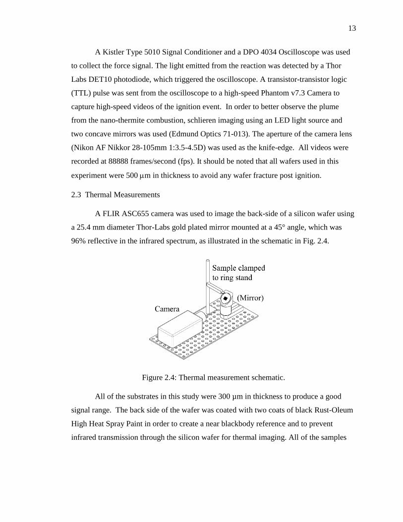
2.3 Thermal Measurements
A FLIR ASC655 camera was used to image the back-side of a silicon wafer using
a 25.4 mm diameter Thor-Labs gold plated mirror mounted at a 45° angle, which was
96% reflective in the infrared spectrum, as illustrated in the schematic in Fig. 2.4.
Figure 2.4: Thermal measurement schematic.
All of the substrates in this study were 300 µm in thickness to produce a good
signal range. The back side of the wafer was coated with two coats of black Rust-Oleum
High Heat Spray Paint in order to create a near blackbody reference and to prevent
infrared transmission through the silicon wafer for thermal imaging. All of the samples

14
were ignited using the same spark ignition method described earlier, and all of the
subsequent videos were recorded at 200 fps.
Through video playback on FLIR’s Examin-IR software, a region-of-interest was
created to spatially average the temperature of the wafer’s back side over time, as seen in
Fig. 2.5 The maximum temperature rise, ΔT, was used to determine the heat deposition
within the substrates using equation 2.1:
Q = mCPΔT
The specific heat of silicon used was 0.712 J/gK [36], and the mass of the wafer was
about 117.4 +/- 0.2 mg, based on an average of 24 measurements.
Figure 2.5: Region of interest used to average temperature of wafer.

15
CHAPTER 3: RESULTS AND DISCUSSION
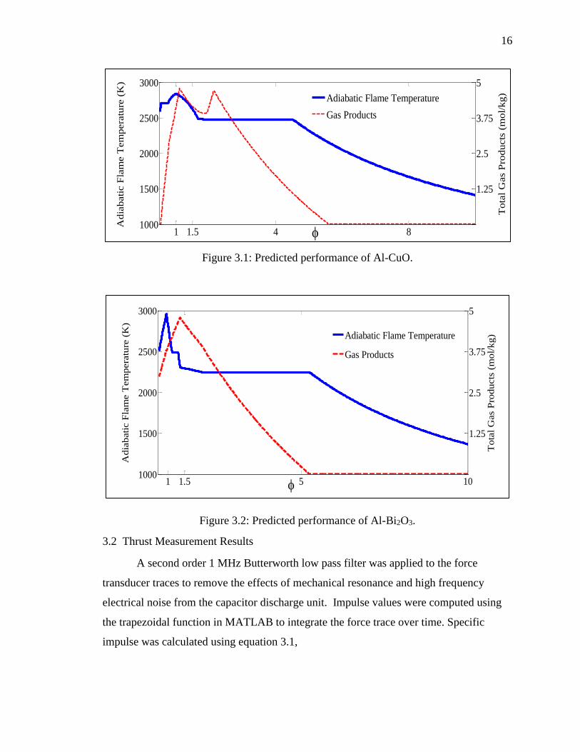
3.1 Thermochemical Equilibrium Calculations
Equilibrium calculations were performed using CHEETAH 7.0, a thermochemical
equilibrium code developed by Lawrence Livermore National Laboratory with a
modified JCZS product library [10]. The fuel-to-oxidizer ratios were varied over the
experimental ranges in order to estimate adiabatic flame temperatures and combustion
products at a constant atmospheric pressure. CHEETAH calculations predict the
maximum adiabatic flame temperatures near stoichiometric conditions for both nano-
thermite systems, as seen in Figs. 3.1 and 3.2.
The Al-CuO system exhibits an adiabatic flame temperature through a wide range
of equivalence ratios as compared to Al-Bi2O3 because of the formation of liquid copper
throughout. Liquid alumina may help to contribute to the high predicted peak
temperature in the Al-Bi2O3 system, but the amounts formed are much lower than that
produced in the Al-CuO system at stoichiometric conditions.
Two peaks in gas generation are observed in the Al-CuO system. The first peak
corresponds to gaseous copper and the second peak results from the formation of Al2O
and Al2O2 gases, that are produced as the mixture becomes more fuel-rich and there is not
enough oxygen to fully oxidize aluminum to Al2O3. Aluminum oxide gases are produced
until approximately =4.5, where the product formation is primarily liquid copper or
solid alumina. In contrast, gaseous bismuth dominates the gas generation in the Al-Bi2O3
system, with the maximum amount being produced at fuel rich conditions.
16
Figure 3.1: Predicted performance of Al-CuO.
Figure 3.2: Predicted performance of Al-Bi2O3.
3.2 Thrust Measurement Results
A second order 1 MHz Butterworth low pass filter was applied to the force
transducer traces to remove the effects of mechanical resonance and high frequency
electrical noise from the capacitor discharge unit. Impulse values were computed using
the trapezoidal function in MATLAB to integrate the force trace over time. Specific
impulse was calculated using equation 3.1,
1 1.5 4 8
1500
2000
2500
3000
1000
Adia
bati
c F
lam
e T
em
pera
ture
(K
)
1.25
2.5
3.75
5
Tota
l G
as
Pro
ducts
(m
ol/
kg)
Adiabatic Flame Temperature
Gas Products
1 1.5 5 101000
1500
2000
2500
3000
Ad
iab
ati
c F
lam
e T
em
pera
ture
(K
)
1.25
2.5
3.75
5
To
tal
Gas
Pro
du
cts
(m
ol/
kg
)
Adiabatic Flame Temperature
Gas Products

17
𝐼sp =∫ F dt
mg, (3.1)
where F is force, m is initial mass of the sample and g is the gravitational constant. Thrust
measurements were conducted on a set of four samples at each equivalence ratio tested.
Peak thrusts divided by sample mass and specific impulses of the samples are plotted in
the bar graphs in Figs. 3.3 and 3.4.
Typical force traces of the Al-CuO samples are shown in Fig. 3.5. As seen in Fig
3.3., thrust generation decreases by more than a factor of two between =1 to =1.5, and
between =1.5 to =4. These observations are similar to what was observed by Sanders et
al., where the peak pressures and combustion velocities occurred near =1.1 [10]. A
shock wave followed by hot reaction products can be visibly seen at stoichiometric
conditions in Fig 3.7. as the reaction propagates very quickly. For more fuel-rich cases,
the reaction is slower with less gaseous products and no shock wave, but the hot reaction
products are still observed. Comparing the experimental results to CHEETAH
calculations suggests that the shock wave formation and the majority of thrust generation
may be largely driven by the production of copper gas since the observed shock
formation corresponds to high predicted gas production. As the mixture becomes more
fuel-rich, there is more variability in the results, likely due to lower flammability and
slower burning rate.
Samples from the very fuel rich Al-CuO (=8) set demonstrated more sample-to-
sample variation. Certain samples from this set exhibited combustion behavior, which
appeared to be driven by a quick burn, possibly a subsonic convection reactive wave. In
Fig. 3.8, an unsteady combustion front causes the reacted or unreacted powders to be
thrown in different directions off the substrate. Other samples ignited within the washers,
but did not emit the necessary amount of light to trigger the photodiode, resulting in no
recorded force signal and indicating a possible slow deflagrative wave. An alternative
triggering mechanism can be used to obtain force signals for such samples, as mentioned
later. Previous literature has reported unsteady combustion behavior and variable reactive
performance at fuel-rich conditions for nano-thermite systems [14].

18
Typical force traces of the Al-Bi2O3 samples can be seen in Fig. 3.6. The
maximum peak thrusts and specific impulses for Al-Bi2O3 are observed at slightly fuel
rich conditions (=1.5). Correlating the observed experimental results to isobaric
CHEETAH calculations, the observed shock waves and thrust generation appears to also
be driven by the rapid formation of gaseous bismuth. Sanders et al. showed that the peak
propagation velocities and pressures were at =1.3 or this system [10]. Compared to
stoichiometric conditions, the propagation velocities at =1.6 were higher, but the
pressures recorded were lower [10]. Samples mixed at an equivalence ratio of =5
generated much weaker shock waves upon ignition and propagated slower than their
stoichiometric counterparts. Based on experimental observations, as seen in Fig. 3.10,
the combustion of the samples prepared at =10 is relatively slow, and solid powders are
released from the substrate over a longer period of time. Attempts were also made to test
dried deposited nano-aluminum (no oxidizer) for thrust measurements, but these samples
failed to ignite with a spark. With the low amounts of material tested in this experiments,
it is likely that the agglomeration and higher densities of these deposited materials
inhibited ignition. Comparable amounts of nano-aluminum powder were instead ignited
for a thrust measurement. Similar to select tests with the very fuel rich Al-CuO, the nAl
ignited within the washers without releasing any products from the substrate. Since the
samples did not generate a recorded force signal using the photodiode, an alternative
triggering mechanism was needed. The signal conditioner was set to the minimum
amplification settings, and the signal output was used to trigger a force measurement.
This verified that the ignition of nAl powders generated negligible amounts of thrust.

19
Figure 3.3: Summary of thrust performance of Al-CuO.
Figure 3.4: Summary of thrust performance of Al-Bi2O3.

20
Figure 3.5: Typical force traces for Al-CuO.
Figure 3.6: Typical force traces for Al-Bi2O3.
Figure 3.7: Schlieren imaging of stoichiometric Al-CuO.
0 100 200 300
0
15
30
45
Time (s)
Thru
st (
N)
=1
=1.5
=4
=8
0 100 200 300
0
100
200
300
Time (s)
Thru
st (
N)
=1
=1.5
=5
=10

21
Figure 3.8: Schlieren imaging of Al-CuO at very fuel-rich conditions (=8).
Figure 3.9: Schlieren imaging of stoichiometric Al-Bi2O3.
Figure 3.10: Schlieren imaging of Al-Bi2O3 at very fuel-rich conditions (=10).
3.3 Thermal Measurement Results
All thermal heating measurements were conducted on a set of four samples at
each equivalence ratio considered. The Al-Bi2O3 samples prepared at =1 and =1.5 were
not tested in this experiment, as the energy generated from these samples fractured the
substrates used. Because deposited nano-aluminum inks were not ignitable with the
spark generator, 4 mg of dry deposited nAl powders were instead used to determine the
22
heating effects. As the nAl powder did not gasify, no products of combustion left the
washer after ignition. Therefore, a greater amount of energy could be effectively
transferred conductively for heating the substrate. All of the substrates showed heating at
low heating rates with spatially uniform temperature distributions throughout. A typical
temperature trace measured on the backside of a silicon wafer can be seen in Fig. 3.11.
Figs 3.12 and 3.14 and summarize the heating results of several Al-CuO samples.
While fuel-rich samples effectively deposit more heat into substrates, there is larger
variability between tests. Nano-thermites at fuel rich conditions can display more
stochastic combustion behavior between samples that are presumably propagating within
a subsonic convection regime, as observed in other work for fuel-rich nano-thermites.
One of the four samples from the =8 set produced very slow heating and a slow cool-off
on the backside, similar to the behavior observed in the nAl powder ignition.
The other samples from the =8 set generated similar amounts of heat within the
substrates as compared to the =4 samples, although there was a significant decrease in
the heating rate, as seen in Fig 3.12. The variability in the heating performance of the
fuel-rich Al-CuO nano-thermites can also be attributed to the significant decrease in their
sensitivity to electro-static discharge [37]. The reduction in electrostatic sensitivity could
increase ignition delays, changing the overall ignition time of each sample prepared at
such conditions.
Fuel rich Al-Bi2O3 formulations were observed to be less effective at heating the
silicon substrates, but do exhibit quick heating profiles (see Figs. 3.13 and 3.15),
performing similarly to stoichiometric and near-stoichiometric Al-CuO. Despite a
significant reduction in gas generation, there is less condensed phase product formation
necessary for larger amounts of energy transfer within the substrate. As indicated by the
schlieren imaging, ignition of the samples prepared at = 10 result in solid products
being thrown away from the substrate over time. It is also possible that some of these
samples exhibit incomplete combustion, with the partially combusted products
propagating away from the substrate.

23
Figure 3.11: A typical nAl temperature trace measured on the back side of a wafer.
Figure 3.12: Typical Al-CuO temperature traces.
Figure 3.13: Typical Al-Bi2O3 temperature traces.

24
Figure 3.14: Summary of heat deposition with Al-CuO samples.
Figure 3.15: Summary of heat deposition with Al-Bi2O3 samples.

25
CHAPTER 4: CONCLUSIONS AND FUTURE WORK
This work describes experiments used to quantify the thrust and heating in
electronic circuit analogues integrated with nano-thermite based energetic materials.
Nano-thermites processed through resonant mixing methods were deposited into washers
attached to silicon substrates. Tests were conducted on the dried nano-thermites (4 to 5
mg) to determine thrust generation using a force transducer and heat deposition into
silicon substrates using infrared thermometry. At near stoichiometric conditions, both Al-
CuO and Al-Bi2O3 generated maximum thrusts and shock-wave formation was visible in
schlieren imaging. The tradeoff between thrust and heat deposition was clearly visible by
altering stoichiometry, as increased heat deposition was observed with fuel-rich nano-
thermite formulations, and the reduction in gas generation resulted in more hot products
remaining on the substrates post ignition. The results seen through experimentation
match thermochemical equilibrium calculations predicted by CHEETAH 7.0.
More stochastic combustion behavior was observed with fuel-rich Al-CuO
formulations, resulting in different conductive heating performances between samples.
As nano-thermite formulations failed to spark ignite beyond a certain threshold, nano-
aluminum powder ignition was tested to determine heat deposition. With very few hot
reaction products leaving the substrates, most of the combustion energy was effectively
transferred into conductively heating the silicon substrates.
The low quantity of materials tested in these experiments could potentially
represent a simplified version of existing micro-electronic devices integrated with
energetic material. While this paper focused solely on nano-thermite formulations, these
experiments could be used to quantify other nano-thermite formulations as well as other
classes of energetic materials that propagate well at the microscale.

26
There is a wide number of combinations possible for mixing other nano-thermite
systems. Utilizing other nano-scale metal oxides with lower densities may be useful
forcreating nano-thermite inks with a lower likelihood of phase separation. The addition
of the appropriate dispersants may also help to increase the shelf life of nano-thermite
inks and allow for the possibilities of inkjet printing.
Future work could also investigate the effects of incorporating various binders on
thrust and heat deposition. In addition to particular fluoropolymers and nitrocellulose
that have been used in the past with nano-thermites, the addition of a conductive polymer
into a nano-thermite mixture should be investigated for its potential use in a conductive
bridgewire application. Different nanoaluminum-fluorocarbon mixtures would also be
worth considering for these experiments. Other materials that could be tested for micro-
energetic applications include intermetallic and high nitrogen materials.

28
LIST OF REFERENCES

27
LIST OF REFERENCES
1. Dreizin, E. L. (2009). Metal-based reactive nanomaterials. Progress in Energy and
Combustion Science, 35(2), 141–167.
2. Son, S. F., Asay, B. W., Foley, T. J., Yetter, R. A., Wu, M. H., and Risha, G. A.
(2007). Combustion of Nanoscale Al/MoO3 Thermite in Microchannels. Journal of
Propulsion and Power, 23(4), 715–721.
3. Sundaram, D. S., Yang, V., and Zarko, V. E. (2015). Combustion of nano aluminum
particles (Review). Combustion, Explosion, and Shock Waves, 51(2), 173–196.
4. Foley, T. J., Johnson, C. E., and Higa, K. T. (2005). Inhibition of Oxide Formation
on Aluminum Nanoparticles by Transition Metal Coating. Chemistry of Materials,
17(16), 4086–4091.
5. Wang, L. L., Munir, Z. A., and Maximov, Y. M. (1993). Thermite reactions: their
utilization in the synthesis and processing of materials. Journal of Materials Science,
28(14), 3693–3708.
6. Fischer, S. H., and Grubelich, M. C. (1998). Theoretical energy release of thermites,
intermetallics, and combustible metals (No. SAND--98-1176C; CONF-980728).
Sandia National Labs., Albuquerque, NM (US).
7. Pantoya, M. L., and Granier, J. J. (2005). Combustion Behavior of Highly Energetic
Thermites: Nano versus Micron Composites. Propellants, Explosives, Pyrotechnics,
30(1), 53–62.
8. Piercey D.G. and Klapotke T.M. (2010), “Nanoscale Aluminum – Metal oxide
(thermite) reactions for application in energetic materials”, Central European
Journal of Energetic Materials, 7(2), 115–129.
9. Puszynski, J. A., Bulian, C. J., and Swiatkiewicz, J. J. (2007). Processing and
Ignition Characteristics of Aluminum-Bismuth Trioxide Nanothermite System.
Journal of Propulsion and Power, 23(4), 698–706.
10. Sanders, V. E., Asay, B. W., Foley, T. J., Tappan, B. C., Pacheco, A. N., and Son, S.
F. (2007). Reaction Propagation of Four Nanoscale Energetic Composites
(Al/MoO3, Al/WO3, Al/CuO, and B12O3). Journal of Propulsion and Power, 23(4),
707–714.

28
11. Nellums, R. R., Terry, B. C., Tappan, B. C., Son, S. F., and Groven, L. J. (2013).
Effect of Solids Loading on Resonant Mixed Al-Bi2O3 Nanothermite Powders.
Propellants, Explosives, Pyrotechnics, 38(5), 605–610.12.
12. Bockmon, B. S., Pantoya, M. L., Son, S. F., Asay, B. W., and Mang, J. T. (2005).
Combustion velocities and propagation mechanisms of metastable interstitial
composites. Journal of Applied Physics, 98(6), 1-7.
13. Zachariah, M. R., and Egan, G. C. (2016). Chapter Four - Mechanisms and
Microphysics of Energy Release Pathways in Nanoenergetic Materials. In Zarko, V.
E. & Gromov, A. A. (Eds.), Energetic Nanomaterials (pp. 65–94). Amsterdam:
Elsevier.
14. Dutro, G. M., Yetter, R. A., Risha, G. A., and Son, S. F. (2009). The effect of
stoichiometry on the combustion behavior of a nanoscale Al/MoO3 thermite.
Proceedings of the Combustion Institute, 32(2), 1921–1928.
15. Foley, T., Pacheco, A., Malchi, J., Yetter, R., and Higa, K. (2007). Development of
Nanothermite Composites with Variable Electrostatic Discharge Ignition Thresholds.
Propellants, Explosives, Pyrotechnics, 32(6), 431–434.
16. Malchi, J. Y., Yetter, R. A., Foley, T. J., and Son, S. F. (2008). The Effect of Added
Al2O3 on the Propagation Behavior of an Al/CuO Nanoscale Thermite. Combustion
Science and Technology, 180(7), 1278–1294.
17. Levitas, V. I., Asay, B. W., Son, S. F., and Pantoya, M. (2007). Mechanochemical
mechanism for fast reaction of metastable intermolecular composites based on
dispersion of liquid metal. Journal of Applied Physics, 101(8), 1-20.
18. Jian, G., Chowdhury, S., Sullivan, K., and Zachariah, M. R. (2013). Nanothermite
reactions: Is gas phase oxygen generation from the oxygen carrier an essential
prerequisite to ignition? Combustion and Flame, 160(2), 432–437.
19. Sullivan, K. T., Piekiel, N. W., Wu, C., Chowdhury, S., Kelly, S. T., Hufnagel, T.
C., Fezzaa, K., and Zachariah, M. R. (2012). Reactive sintering: An important
component in the combustion of nanocomposite thermites. Combustion and Flame,
159(1), 2–15.
20. Egan, G. C., LaGrange, T., and Zachariah, M. R. (2015). Time-Resolved
Nanosecond Imaging of Nanoscale Condensed Phase Reaction. The Journal of
Physical Chemistry C, 119(5), 2792–2797.

29
21. Puchades, I., Hobosyan, M., Fuller, L. F., Liu, F., Thakur, S., Martirosyan, K. S., and
Lyshevski, S. E. (2014). MEMS microthrusters with nanoenergetic solid propellants.
In 14th IEEE International Conference on Nanotechnology (pp. 83–86).
22. Smolker, G., and Chernick, L. (1975, May 6). United States Patent: 3882324 -
Method and apparatus for combustibly destroying microelectronic circuit board
interconnections.
23. Smolker, G. (1975, May 6). United States Patent: 3882323 - Method and apparatus
for protecting sensitive information contained in thin-film microelectronic circuitry.
24. Benson, D. A., Larsen, M. E., Renlund, A. M., Trott, W. M., and Jr, R. W. B. (1987).
Semiconductor bridge: A plasma generator for the ignition of explosives. Journal of
Applied Physics, 62(5), 1622–1632.
25. Nellums, R. R., Son, S. F., and Groven, L. J. (2014). Preparation and
Characterization of Aqueous Nanothermite Inks for Direct Deposition on SCB
Initiators. Propellants, Explosives, Pyrotechnics, 39(3), 463–470.
26. Rossi, C., and Estève, D. (2005). Micropyrotechnics, a new technology for making
energetic microsystems: review and prospective. Sensors and Actuators A: Physical,
120(2), 297–310.
27. Rossi, C., Zhang, K., Esteve, D., Alphonse, P., Tailhades, P., and Vahlas, C. (2007).
Nanoenergetic Materials for MEMS: A Review. Journal of Microelectromechanical
Systems, 16(4), 919–931.
28. Pezous, H., Rossi, C., Sanchez, M., Mathieu, F., Dollat, X., Charlot, S., and
Conédéra, V. (2010). Fabrication, assembly and tests of a MEMS-based safe, arm
and fire device. Journal of Physics and Chemistry of Solids, 71(2), 75–79.
29. Bergthorson, J. M., Goroshin, S., Soo, M. J., Julien, P., Palecka, J., Frost, D. L., and
Jarvis, D. J. (2015). Direct combustion of recyclable metal fuels for zero-carbon heat
and power. Applied Energy, 160, 368–382.
30. Rossi, C., Estève, D., and Mingués, C. (1999). Pyrotechnic actuator: a new
generation of Si integrated actuator. Sensors and Actuators A: Physical, 74(1–3),
211–215.
31. Koninck, D. A. de, Briand, D., Guillot, L., Bley, U., Gass, V., and Rooij, N. F. de.
(2011). Ignition and Combustion Behavior in Solid Propellant Microsystems Using
Joule-Effect Igniters. Journal of Microelectromechanical Systems, 20(6), 1259–
1268.

30
32. Apperson, S. J., Bezmelnitsyn, A. V., Thiruvengadathan, R., Gangopadhyay, K.,
Gangopadhyay, S., Balas, W. A., Anderson, P. E., and Nicolich, S. M. (2009).
Characterization of nanothermite material for solid-fuel microthruster applications.
Journal of Propulsion and Power, 25(5), 1086–1091.
33. Staley, C. S., Raymond, K. E., Thiruvengadathan, R., Herbst, J. J., Swaszek, S. M.,
Taylor, R. J., Gangopadhyay, K, and Gangopadhyay, S. (2014). Effect of
Nitrocellulose Gasifying Binder on Thrust Performance and High-g Launch
Tolerance of Miniaturized Nanothermite Thrusters. Propellants, Explosives,
Pyrotechnics, 39(3), 374–382.
34. Staley, C. S., Raymond, K. E., Thiruvengadathan, R., Apperson, S. J.,
Gangopadhyay, K., Swaszek, S. M., Taylor, R. J., and Gangopadhyay, S. (2015).
Fast-Impulse Nanothermite Solid-Propellant Miniaturized Thrusters. Journal of
Propulsion and Power, 31(1), 483–483.
35. Ru, C., Wang, F., Xu, J., Dai, J., Shen, Y., Ye, Y., Zhu, P., and Shen, R. (2016).
Superior performance of a MEMS-based solid propellant microthruster (SPM) array
with nanothermites. Microsystem Technologies, 1–14.
36. Bergman, T. L., Lavine, A.S., Incropera, F. P., and DeWitt, D. P.
(2011). Fundamentals of heat and mass transfer, New York, NY: John Wiley &
Sons.
37. Steelman, R., Clark, B., Pantoya, M. L., Heaps, R. J., and Daniels, M. A. (2015).
Desensitizing nano powders to electrostatic discharge ignition. Journal of
Electrostatics, 76, 102–107.

APPENDICES

31
APPENDIX A: NANO-THERMITE MIXING PROCEDURE
Procedure For:
Preparation of 500 milligrams of Nanothermite through
Resodyn mixing. Deposition of Nanothermite Ink
Droplets.
Date Created/Created By: 02/04/2015 Raghav Ramachandran
Location: ZL4 Rooms 110 and 116.
Notes:
Potential hazards and Mitigation:
● Unintentional ignition of reacted material – Use of PPE (appropriate gloves,
cotton clothing, eye protection, hearing protection, ESD strap), Keep away from
open flame. Minimize amounts in storage.
● Unintentional exposure to organic solvents – Work in fume hood. Wear
appropriate goggles and gloves.
● Unintentional exposure to nanomaterials – Work in fume hood. Wear appropriate
goggles and gloves.
● Unforeseen circumstances/accidents – two people present and aware during
experimentation.
Section 1 – PPE to be used during operation ☐ 1. Fume hood
☐ 2. Cotton/organic fiber clothing/lab coat (no nylon/synthetic fiber)
☐ 3. Nitrile gloves
☐ 4. Leather gloves
☐ 5. Face shield
☐ 6. Hearing protection
☐ 7. Safety glasses
☐ 8. Long pants
☐ 9. Close-toed shoes
☐ 10. Waste container.
Section 2 – Chemicals/Materials/Equipment required ☐ 1. Nano-Aluminum Powder.

32
☐ 2. Nanopowder Metal Oxides : Bismuth oxide, copper oxide, or molybdenum
oxide.
☐ 3. Surfactant: PVP for example.Solvent : DMF, Hexanes, IPA, Acetone, Ethanol, or
Methanol. Note that alcohols can react slowly with nano-aluminum.
☐ 4. 325 Mesh Sieve.
☐ 5. Sieve Shaker.
☐ 6. Metal Brush.
☐ 7. Water
☐ 8. 10 mL BD Syringe
☐ 9. PTFE Holder for BD Syringe
☐ 10. AIRTECH Flashbreaker 1 Tape
☐ 11. Dispersing Needle
☐ 12. Scale
☐ 13. Resodyn Acoustic Mixer
Section 3 – Preparation of Nanothermite Ink through Resodyn mixing. ☐ 1. Make sure that a water-filled container for waste disposal is present near the
fume hood. Refer to Section 5.1 for more details.
☐ 2. Ensure that all nanopowders are separately sieved in the fume hood using a 325
mesh sieve before any sort of mixing. Place sieve on pan on vibrator/sieve shaker. If
necessary, use an appropriate metal brush to sieve nanoparticles.
☐ 3. Always ensure that the brush and sieve are clean when a new material is being
sieved.
☐ 4. Cover the BD Syringe tip with a small piece of the AIRTECH tape.
☐ 5. Remove plunger from the syringe.
☐ 6. Measure the appropriate amount of surfactant and deposit into the BD Syringe.
☐ 7. Measure the appropriate amount of nanoaluminum and deposit into the BD
Syringe. Note that nanoaluminum needs to be removed from the glovebox in room 103.
☐ 8. Measure the appropriate amount of metal oxide powder and deposit into the BD
Syringe.
☐ 9. Nearly invert syringe (tip up) and tap with spatula to clear syringe tip. Add the
appropriate amount of solvent using the variable volume pipette. Make sure solvent does
not reach tip.
☐ 10. Remove tape from syringe tip and vent (depress plunger) until 1mL of volume
remains. Reseal Tip.
☐ 11. Carefully insert syringe into PTFE holder. Cut the plunger with a razor blade
such that the syringe is flush with the bottom of the PTFE holder.
☐ 12. Place sample in Resodyn in a remote room. Be sure that sample is properly
clamped in place with the lock nut tightened, and that the mixing container bottom is
seated inside the raised outer shoulder.
☐ 13. Put on leather gloves, hearing protection, face shield, and lab coat. Place sample
in Resodyn in room 116.
☐ 14. Verify that no personnel are present in the mixing room and close all mixing
room doors.
☐ 15. Connect to COM port 2 on RAMWARE. Verify connection and operation of
remote monitor station before beginning to mix.
33
☐ 16. Start Resodyn mixing at 0% intensity and quickly ramp up to 80% and run for
480 seconds. Invert sample in Resodyn and repeat steps 11-13. This must be done in
60 seconds. ☐ 17. Follow the procedures outlined in Section 4.
Section 4 – Transportation of Material ☐ 1. Carefully remove BD Syringe from the PTFE Holder. Pull the plunger back a
little bit before the full syringe is removed.
☐ 2. Carefully remove tape from syringe tip.
☐ 3. Transfer materials from syringe into the ~2.5mL plastic vials.
☐ 4. Place syringe and tape in waste container.
☐ 5. Carefully position materials in an appropriate ammo box and store in fume hood.
☐ 6. Place a sign on the box informing other students that only Dr. Son, Gunduz, and
Rhoads are authorized to transport the material.
Section 5 – Storage, Handling, and Disposal of Nanothermite Inks ☐ 1. Fill a container (usually a Menards green pail is used) with water.
☐ 2. Handling: After the nanothermite ink dries, it becomes very ESD sensitive. When
handling this material, the following PPE must be used: face shield, hearing protection,
leather gloves, ESD strap, and lab coat.
☐ 3. Disposal: Place BD syringe, weighing papers in the waste, and any kim wipes
with nanothermite ink residue into waste container.
Section 6 – Emergency Procedures ☐ 1. Unintentional ignition of material resulting in bodily injury: If minor injury is
sustained from the incident (e.g., minor burns), treat with appropriate first aid and contact
a supervisor. If major injury is sustained, immediately call 911 and then contact a
supervisor.
☐ 2. Unintentional ignition of material resulting in uncontrolled fire: Ensure that fire
is extinguished using appropriate fire extinguisher and then contact a supervisor. If fire is
sufficiently uncontrolled, immediately pull a fire alarm, evacuate the building, call 911,
and then contact a supervisor. If a fire is sufficiently controlled (e.g., unintentional
ignition of paper on a burn plate), let the fire self-extinguish, and then contact a
supervisor.
☐ 3. Unforeseen injury: If minor injury is sustained from the incident (e.g., cuts,
minor burns, etc.), treat with appropriate first aid and immediately contact a supervisor. If
major injury is sustained, call 911 and then contact a supervisor.

34
APPENDIX B: SAMPLE MIXING SHEET
Reaction Equation
Al + 3/2 CuO ----> 1/2 Al2O3 + 3/2 Cu
Enter total amount of nanothermite (g). 0.50
Enter mass percentage of surfactant used (%). 0.00
Total amount of Nanothermite desired to be mixed (g). 0.50
Enter the Percentage of Active Aluminum in nAl (%) 82.00
Enter Phi (Equivalence Ratio) 4.00
Amount Surfactant 0.00
MW of Aluminum (g/mol) 26.98
MW of Aluminum Oxide (g/mol) 101.96
MW of Copper Oxide (g/mol) 79.55
Mass Fraction Aluminum in nAl 0.82
Mass Fraction Aluminum Oxide in nAl 0.18
Mole Fraction Aluminum in nAl 0.95
Mole Fraction Aluminum Oxide in nAl 0.05
Moles of Alumina (Product in Reaction) 0.53
Moles of Copper Oxide 1.42
Mass Fraction nAl (stoichiometric conditions) 0.22
Mass Fraction Copper Oxide (stoichiometric conditions) 0.78

35
Amount of Novacentrix nAl needed (stoichiometric conditions) 0.11
Amount of Copper Oxide needed (stoichiometric conditions) 0.39
Fuel to Oxidizer Ratio (Stoichiometric Conditions and mass based) 0.28
Fuel to Oxidizer Ratio (Actual) 1.10
Amount of Novacentrix nAl needed (g) 0.26
Amount of Copper Oxide needed (g) 0.24
Enter the volumetric solids loading. 10.30
Density of Aluminum (g/mL) 2.70
Density of Aluminum Oxide (g/mL) 3.95
Density of Copper Oxide (g/mL) 6.31
Density of Surfactant (g/mL) 1.20
Volume of Al-CuO Nanothermite (mL) 0.13
Volume of Nanothermite and Surfactant (mL) 0.13
Volume of Solvent needed (mL) 1.13
Total Volume 1.26