re ps 02-005-2012 revision 5 - tmk-group.com · re ps 02-005-2012 revision 5 ... - crews for tubing...
TRANSCRIPT


RE PS 02-005-2012 Revision 5
Page 2 of 33
Contents
Introduction………………………………………………………………………………………….. 3
1 Scope………………………………….………………………………………………………....
2 References………………………………………………………………………………………
3 Terms and definition……..……………………………………………………………………..
4 Transportation…………………………………………………………………………………
5 Handling operations………………………………………………………………………….
6 Stockholding and storage….………………………………….…………………………….
7 Preparation……………………..………………………………….......................................
8 Application of thread compound……………………………………..……………………..
9 Trip..…..……………………………………………………..……………….….....................
10 Manufactures warranty……………………………………………………………..………...
Attachment А (mandatory) Equipment for make-up registration …………………..……….
Attachment B (mandatory) Restoration of make-up marks and cross stripe………………
4
4
4
5
5
6
7
11
13
29
30
31

RE PS 02-005-2012 Revision 5
Page 3 of 33
Introduction
The present instructions are governed by the following documents:
- API RP 5C1 Recommended Practice for Care and Use of Casing and Tubing;
- API RP 5В1 Gaging and Inspection of Casing, Tubing and Pipe Line Threads;
- ISO 10405 Petroleum and Natural Gas Industries – Care and Use of Casing and Tubing.

RE PS 02-005-2012 Revision 5
Page 4 of 33
Guidelines for use tubing with thread connection ТМК UP РF
Effective date 12–12–2014
1 Scope
The present instructions contain recommendations for maintenance and use of tubing withTMK UP РF threaded connections under field conditions including pipe preparation and make-up,string running and pulling operations, as well as guidelines for pipe handling, storage and inspectionduring operation.
2 References
The present instructions refer to the following documents:
API RP 5A3/ISO 13678 Recommended Practice on Thread Compounds for Casing, Tubing,and Line Pipe
NOTE: For dated references only the edition cited shall apply. For undated references thelatest edition of the referenced document shall apply.
3 Terms and definitions
For the purposes of these instructions, standard terms shall apply as well as the followingterms and definitions:
3.1 seal assembly: Assemblage of seal and shoulder elements of thread connection.
3.2 thread connection torqueing during assembly operations: Preselected travel of thethreaded connection in a circumferential direction after it shoulder elements interlock.
3.3 pin: Thread connection element, made on the outer surface of the pipe end, containingexternal thread, external radial seal and a shoulder.
3.4 coupling: Thread connection element, made on the inner surface of the pipe end,containing internal thread, internal radial seal and a shoulder.
3.5 thread connection seal elements: Pin external radial seal and coupling internalradial seal
3.6 thread connection shoulder elements: Pin shoulder and coupling shoulder
3.7 pin shoulder: Pin surface located at an angle to the pin axis, acting as an arresterduring make-up procedure.
3.8 coupling shoulder: Coupling surface located at an angle to coupling axis, acting as anarrester during make-up procedure.

RE PS 02-005-2012 Revision 5
Page 5 of 33
4 Transportation
4.1 When pipes are transported by sea, railroad (railcars) or trucks, Cargo Shipping Rules andTechnical Provisions for Cargo Handling and Fastening applicable at the particular transport type shall bepracticed.
4.2 Pipe transportation, handling and storage shall be carried out with thread protectors forpipes and couplings in order to protect them from exposure.
4.3 Pipes of different batches and standard sizes can be loaded onto same means oftransportation, but have to be separated.
4.4 Pipe packages shall be securely fastened for transportation to avoid any movement.Wooden blocks can be used for fastening purposes.
When several pipes packages are stacked or not packaged pipes are put into ranks. Pipepackages shall be separated by at least three wooden blocks, each 1,4 – 1,6 inch thick that weight ofupper pipes do not distribute onto couplings of lower rows.
4.5 When transported by water, pipe packages shall not be placed in the water inside thevessel’s hold or in any other corrosive environment. Dragging of bundles along the piles or hittingbundles against hatches or rails is strictly forbidden.
4.6 While loading pipe packages into railway cars or trucks, wooden girders (blocks) shall beprovided for car floors or vehicle beds to ensure required distance between the products and uneven bottomof the vehicle. No blocks shall be placed under couplings.
4.7 Tubes made of steel with content of 9% chrome and more (further – chromium steel) shall bebundled with wooden or plastic blocks.
4.8 In order to prevent tubes from hitting against transport vehicle metal units and prominent partsof the neighboring bundles it is recommended to use a cargo platform with protecting covers.
4.9 When chromium steel tubes fastened to cargo platform or boat deck, nylon harnesses shall beused.
5 Handling operations
5.1 All handling operations shall be carried out with thread protectors on pipe ends andcouplings.
5.2 Handling operations with pipe bundles shall be carried out using only hoistingtransportation clamps.
In case of manual pipe unloading, rope slings shall be used and pipes shall be rolled alongguides in parallel to the pile avoiding quick movement and collision of pipe ends that might result inthread damage even with protectors in place.
When using the crane, spreader beams with slings shall be used according to approvedslinging diagrams.
5.3 Pipes shall not be allowed to fall down from heights or be picked up by the upper pipeend with a hook or be dragged or subjected to any other actions that might damage pipe and couplingthreads, surfaces or shapes.
5.4 Handling operations with chromium steel pipes shall be performed with using nylon orsteel harnesses with plastic braid. When using the crane gripping forks, frames and clamps withnonmetallic coating shall be employed.

RE PS 02-005-2012 Revision 5
Page 6 of 33
5.5 Handling operation for chromium steel pipes shall be performed without collision with hadbodies or sharp edges that can perform to local increasing of pipes surfaces hardness andinfluence on the sulfide cracking resistance with voltage.
6 Stockholding and storage
6.1 Pipes shall be stored as per Materials, Equipment and Spare Parts Storage Guidelinesfor production and technical maintenance facilities ensuring their preservation and avoiding damageof pipe and coupling threads, surfaces or shapes.
6.2 Pipe bundles shall be laid on supports spaced in a manner avoiding sagging or threaddamage. Rack supports shall be located in one plane and shall not sag under pile weight. Rackbearing surface shall be 12 inches above the ground or floor.
Pipe bundles shall not be laid on the ground, rails, steel or concrete floor!
It shall be no stones, sand, dirt on racks!
6.3 When pipe packages are laid into a pile or in several layers not connected into thepackage at least three wooden blocks, each 1,4…1,6 inch thick, shall be provided between them sothat the weight of upper pipes is not applied to couplings in lower layers.
The height of the pipe pile shall not exceed 10 ft.
6.4 For unbundled pipes, it is recommended to install vertical stanchions in the racks.
6.5 If pipes are rolled on the racks, any movements at an angle to the rack axis shall beavoided as that might results in the collision of pipe ends and thread or protector damage.
6.6 While in storage, the presence and integrity of thread protectors shall be inspected, aswell as compound underneath and its expiration date. Pipe corrosion shall be prevented.
6.7 While storage of pipes more than 6 months before usage, compound under safety compo-nents shall be replaced.
Following actions are required:
- remove thread protectors according to 7.1.3;
- remove the compound according to 7.1.4;
- apply rust-preventing compound (Kendex OCTG, Total Jet Marine, EONFILM 300 ThreadProtection Compound or similar), with effective date expired not less than in 6 months – until the nextcompound replacement or pipes usage;
- install thread removed before protectors which were cleaned from compound or new threadprotectors;
6.8 Pipes damaged during transportation, rejected during inspection, prepared for repairs orawaiting a final decision shall be stored in separate racks with corresponding tags.
6.9 While storage chromium steel pipes wood or steel gasket shall be lied onto all pipe bearing.
6.10 Drilling site shall have special area for pipes storage according to above-listed require-ments.
6.11 To supply the full pipes buckle at drilling site it shall be installed required number ofracks shall be install.

RE PS 02-005-2012 Revision 5
Page 7 of 33
While racking it is important to consider the order of string running (if it is defined by workinstruction) to be sure that first pipe is not lied under the pipes that need to be run after. Pipes on tothe rigs shall be placed in such way that couplings are turner to the drilling site.
7 Preparation
7.1 Pipes inspection
7.1.1 Prior to lifting the pipes onto the rig site, proceed as follows:
inspect pipes and couplings visually;
remove thread protectors from pipes and couplings;
remove preservation compound from threaded connections;
inspect threaded connections;
drift pipes along the entire length;
measure the length of each pipe;
re-install clean thread protectors on pipes and couplings
7.1.2 Visual inspection of pipes, couplings and thread protectors is intended for detection ofbent pipes, buckles and damage.
Visual inspection of pipes and couplings shall be carried out without the removal of protectors.
Pipes, couplings, thread protectors with significant damage discovered during the visualinspection shall be put aside awaiting decision on their suitability for use.
Amount of damaged pipes and couplings shall be specified in the Product QualityDiscrepancy Protocol and all damaged areas shall be documented on photographs.
7.1.3 Thread protectors shall be removed after threaded connections are to be visuallyinspected.
Thread protectors shall be removed manually or using the key by one person. In case ofdifficulties removing protectors they can be heated by steam or taken off with the help of a woodenhammer in case of distortion.
7.1.4 Upon removal of thread protectors, threaded connections shall be cleaned fromcompound applying pressurized hot soapy water or using steam cleaner. Water should be underpressure. In case of freezing temperature, compound can be removed using solvent (WhiteSpirit or similar). Upon compound removing thread connection shall be blast by compressed air orcleaned with dry rags.
Compound shall not be removed usingdiesel, kerosene, salty water, barite or metal brushes!
Barite or metal brushes can cause scratches on seal surfaces resulting in loss of tightness.
Upon compound removal threaded connections shall be wiped with a dry and clean cloth ordried using compressed air.

RE PS 02-005-2012 Revision 5
Page 8 of 33
7.1.5 While using under thread protectors thread sealing compound, the compound removalis not require. You need to be sure in following:
- lack of extraneous substance in compound;
- smoothness of compound application onto thread (smooth the surface and/or add thecompound of the same type);
- service life of compound is not expired.
7.1.6 Threaded connection shall be inspected by specialists:
- crews for tubing assembly;
- companies specialized in tubing inspection.
When running casing for the first time, representatives of the casing supplier shall bepresent.
Inspecting threaded connections of pipes and couplings (including thread surface, seal andshoulder elements) special attention shall be paid to:
- damage resulting from pipe collisions or other impacts;
- damage caused during the installation of thread protectors;
- rust, corrosion or other chemical damage due to environmental exposure or aggressivecompound compounds
If underlighting (twilight, night) it shall be used portable light source for individual usageduring inspection.
Possible types of damage to thread, seal and shoulder surfaces of pipes and couplings, aswell as repair methods are specified in Table 1.
7.1.7 Depth of corrosion, burrs, tears, burrs height and scratches shall be determined using:
- Mould of the defect using special tape (X-Coarse by Testex for defects up to 0,004 inchdeep, for deeper faults: X-Coarse Plus or equivalent) and measuring it with thickness gage. Precisionof measurement shall be at least 0,0004 inch (PEACOCK G2-127 or equivalent);
- Depth gage with a needle tip (tip diameter not more than 0,004 inch). Precision ofmeasurement shall be at least 0,0004 inch (PEACOCK Т-4 or equivalent).
If any unacceptable damage is detected, such pipes shall be rejected and reportedaccordingly specifying serial numbers, describing defects found with photos attached.

RE PS 02-005-2012 Revision 5
Page 9 of 33
Таблица 1
Surface Area(Figure 1) Damage Damage Repair
1, 2, 5
Pit corrosion less than 0,0039 inch deepor insignificant surface rust
Manual repair (removal) using non-metal brushwith soft bristle or polishing paper with grain 0
Pit corrosion more than 0,0039 inch deep Not reparableBurrs less than 0,0118 inch wide.Tears and scratches less than 0,0039 inchdeep
Manual repair using needle file or polishingpaper with grain 0
Dents, nicks and other mechanical dam-ages Not reparable
3
Pit corrosion less than 0,0118 inch deepor insignificant surface rust
Manual repair using needle file or polishingpaper
Pit corrosion more than 0,0118 inch deep Not reparableBurrs less than 0,0118 inch wide.Tears and scratches less than 0,0118 inchdeep
Manual repair using needle file or polishingpaper with grain 0
4
Pit corrosion of any depth Not reparableInsignificant surface rust BuffingBurrs, tears and scratches Not reparableDents Not reparableSmall grooves Buffing
а) – Pipe thread, seal and shoulder surfaces
б) – Coupling thread, seal and shoulder surfaces
1 – imperfect profile thread ; 2 – perfect profile thread; 3 – cylinder bore ; 4 – seal taper bore;
5 – shoulder
Figure 1

RE PS 02-005-2012 Revision 5
Page 10 of 33
7.2 Drifting
7.2.1 Pipe should be checked by drift along the entire length of the pipe. For pipes made ofchromium and corrosion-resistant steels polymer or aluminium drifts shall be used.
Before drifting, the pipe shall be positioned in such a manner as to avoid sagging. Shouldany ropes or bars be used for the drifting process make sure they are clean. In case of freezingtemperatures pipes shall be heated with steam prior to drifting, to remove snow and ice crust.
The temperature of pipe shall be equal to the drift temperature during drifting procedure.
Effective dimensions of the drift shall comply with Table 2. Effective diameter of the drift shallbe checked in three planes along the whole length after each 50 pipes. If the diameter decreases bymore than 0,02 inch in any of the three planes, such a drift shall be rejected.
The drift shall pass through the whole pipe, when pulled manually without significant effort.
If the drift cannot pass through the pipe, then such pipe shall be replaced by another pipe.
Pipes rejected during drifting shall be put aside until further decision.
Table 2
In inches
Pipe outside diameter, D Effective length of the drift, Lo Effective diameter of the drift, do
up to 2 7/8 incl. 42 do = d * – 0,094greater than 2 7/8 42 do = d *– 0,125
NOTE: * – nominal pipe inside diameter 1250 (1067)
7.3 Measurement of pipes length
Length of each pipe shall be measured from free (without a thread protector) coupling end tofree (without thread protector) pipe end.
Measured pipe length should be compared to stencilled length. In case of discrepancies themeasured length shall be stated on pipe body with a marker or chalk
When calculating the total length of the string, one should use the formula specified below:
L = ∑Lф – n ΔL
whee: L – the total length of the string;
∑Lф – overall length of pipes in a string, measured from pin end face to free coupling end face;
n – number of pipes in a string;
ΔL – decrease of pipe length during make-up (table 3).
RE PS 02-005-2012 Revision 5
Page 11 of 33
Table 3
In inches
Pipe outer diameter, D Decrease of pipe length during make-up, ΔL
2 3/8 2,8352 7/8 2,9333 1/2 3,232
4 3,5474 1/2 4,079
7.4 Completion of preparation
7.4.1 After inspection and measurements thread protectors or caps shall be re-installed onpipe ends and couplings.
7.4.2 Removed thread protectors can be re-used on the condition that prior to installationthey have been thoroughly cleaned from conservation compound and do not have considerable dam-ages of thread and form.
Cleaning of protectors from compound shall comply with the requirements for cleaningthread connections of pipes and couplings of 7.1.4.
8 Thread compound
8.1 Usage of thread compound
8.1.1 To ensure optimal conditions for make-up and to avoid burrs of mating surfaces, allthread, seal and shoulder surfaces of pipes and couplings shall be provided with thread compound.Thread compound shall comply with API RP 5A3/ISO 13678.
The following thread compounds are recommended:- Bestolife 2000;- Bestolife API Modified Thread Compound;- Jet-Lube Нigh Pressure Modified Thread Compound;
- Jet-Lube Z60 Tool Joint Compound.
Application of the thread compounds is allowed upon coordination with the connectiondesigner; the thread compound shall comply with RP 5A3/ISO 13678 requirements and shallprovide for thread connection sealability as well as for protection from galling and corrosion.
8.1.2 Apply thread compound implementing the following guidelines:
- use the same compound (the same type) when assembling one casing string;- use a new compound package for each running, while usage the compound from opened
package be sure there are no outside material;- stir the compound thoroughly before use;- warm up compound before application in case of low temperatures.
8.1.3 Compound shall be stored in closed overturned packages under temperaturesspecified by the manufacturer. When storing partially unused compound always specify the date ofthe first use.

RE PS 02-005-2012 Revision 5
Page 12 of 33
8.2 Requirements for thread compound
8.2.1 Thread compound for make-up shall be taken only from original packages delivered bythe supplier specifying name, batch number and date of manufacture.
Compound from packages without proper identification shall never be used.
Compound shall never be placed in other packages or thinned!
8.2.2 Compound applied shall be even, of ointment consistency, free from any solidinclusions (stones, sand, dry compound, fine chips, etc.).
8.2.3 Prior to use, check compound’s expiration date on the package. Never applycompound with expired shelf life.
8.3 Calculation of thread compound quantity
8.3.1 Required amount of thread compound shall be distributed between coupling and pipeend as follows: two thirds shall be at the coupling end and one third shall be at the pin.
Minimum and maximal compound mass, mmin and mmax, in grams required for make-up oneconnection shall be calculated as follows:
mmin = 0,11 х D,
mmax = 0,14 х D;
where: mmin – minimum compound mass, g, rounded to the nearest whole number;
mmax – maximum compound mass, g, rounded to the nearest whole number;
D – nominal outside diameter, mm, rounded to the nearest whole number.
Example Minimum thread compound required for make-up one threaded connectionof pipes with nominal diameter of 4,5 inches.
Mmin = 0,11 х 4,5 = 0,4950 0,05 lb.
Here with, at least 0,03 lb. shall be applied on coupling end and at least 0,02 lb. – onpin.
8.3.2 To determine the quantity of compound required for determine the number of pipes itshall be used compound can with known volume.
8.3.3 Prior to running down the hole, make sure that required thread compound have beenapplied.
8.4 Thread compound application
8.4.1 Thread compound shall be applied to all thread, seal and shoulder surfaces of pipesand couplings as plan layer onto all surface of thread, sealing and bearing elements of pipe andcoupling connection. Correct application of thread compound as per figures 2 and 3.
8.4.2 Compound shall be applied only to thoroughly cleaned and dried (as per 7.1.4) surfac-es.
8.4.3 Compound is recommended to be applied on to pin by nylon brush, on to couplings –by relief brush.
Never use metal brushes for compound application!

RE PS 02-005-2012 Revision 5
Page 13 of 33
Figure 2
Figure 3
8.5 Thread compound effect over interlocking torque
When using other compounds the actual make-up torque can differ from the design torque,the final torque value shall be coordinated with the thread connection designers.
9 Trip
9.1 Requirements for trip
9.1.1 Tubing shall be assembled by a qualified operator. To ensure declared parameters ofthread connection, the make-up shall be performed with usage Make-up torque registration system;
If the Make-up torque registration system is not available then the following shall be used inpriority-oriented order:
- tong manometer (translation of pressure into torque in compliance with the wrenchmanufacturer recommendations);
- make-up triangle (cross stripe) and make-up marks.
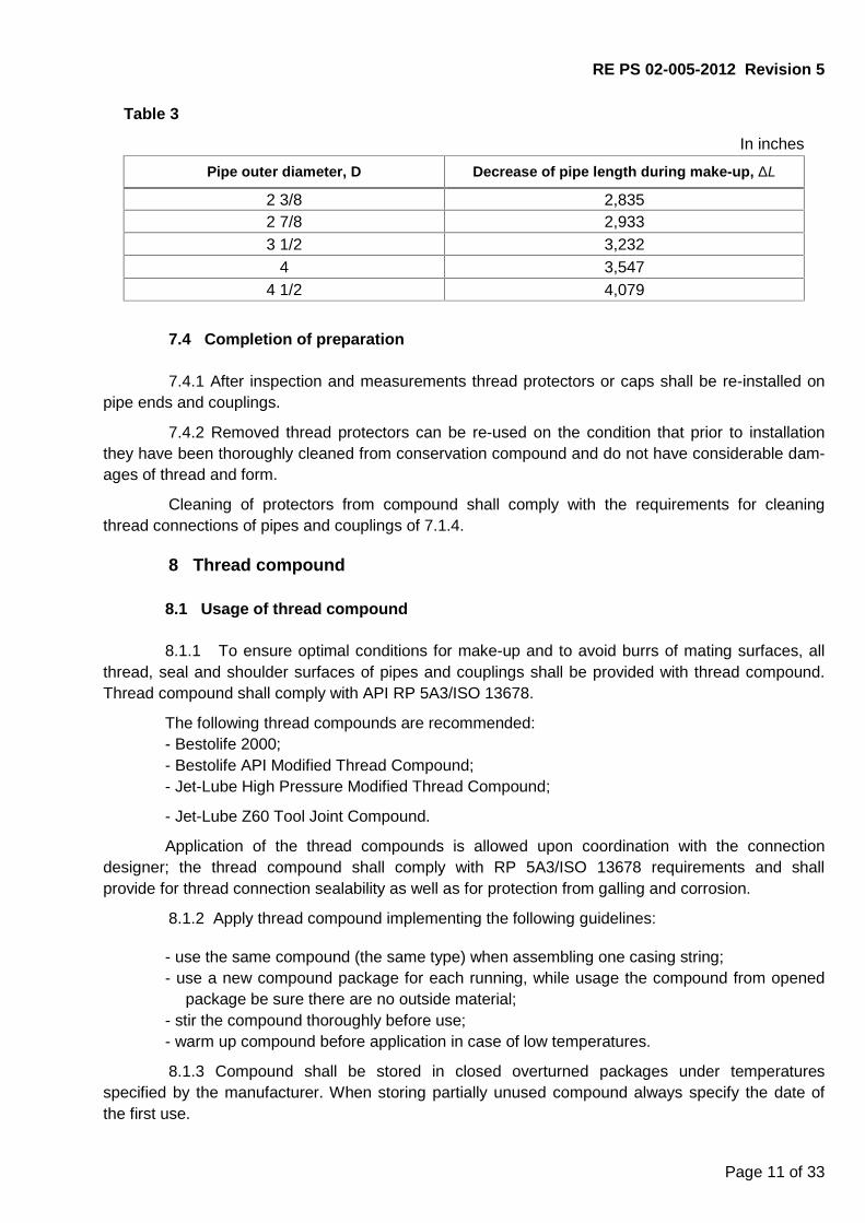
9.1.2 A special bell guide is recommended for trip operations (figure 4). The devices help toalign pin and coupling and prevent the connection from damage.
RE PS 02-005-2012 Revision 5
Page 14 of 33
Figure 4
9.1.3 In order to decrease probability of new damages during chute-lift operations a pipeweight balancer is recommended.
9.1.4 While running of string of chrome steel pipes better to use elevator or special wedgeclaws not to damage the thread.
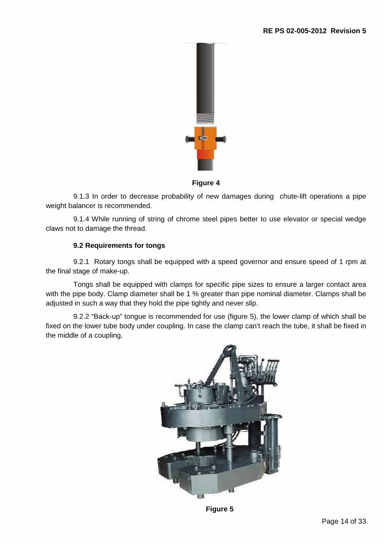
9.2 Requirements for tongs
9.2.1 Rotary tongs shall be equipped with a speed governor and ensure speed of 1 rpm atthe final stage of make-up.
Tongs shall be equipped with clamps for specific pipe sizes to ensure a larger contact areawith the pipe body. Clamp diameter shall be 1 % greater than pipe nominal diameter. Clamps shall beadjusted in such a way that they hold the pipe tightly and never slip.
9.2.2 “Back-up” tongue is recommended for use (figure 5), the lower clamp of which shall befixed on the lower tube body under coupling. In case the clamp can’t reach the tube, it shall be fixed inthe middle of a coupling.
Figure 5
RE PS 02-005-2012 Revision 5
Page 15 of 33
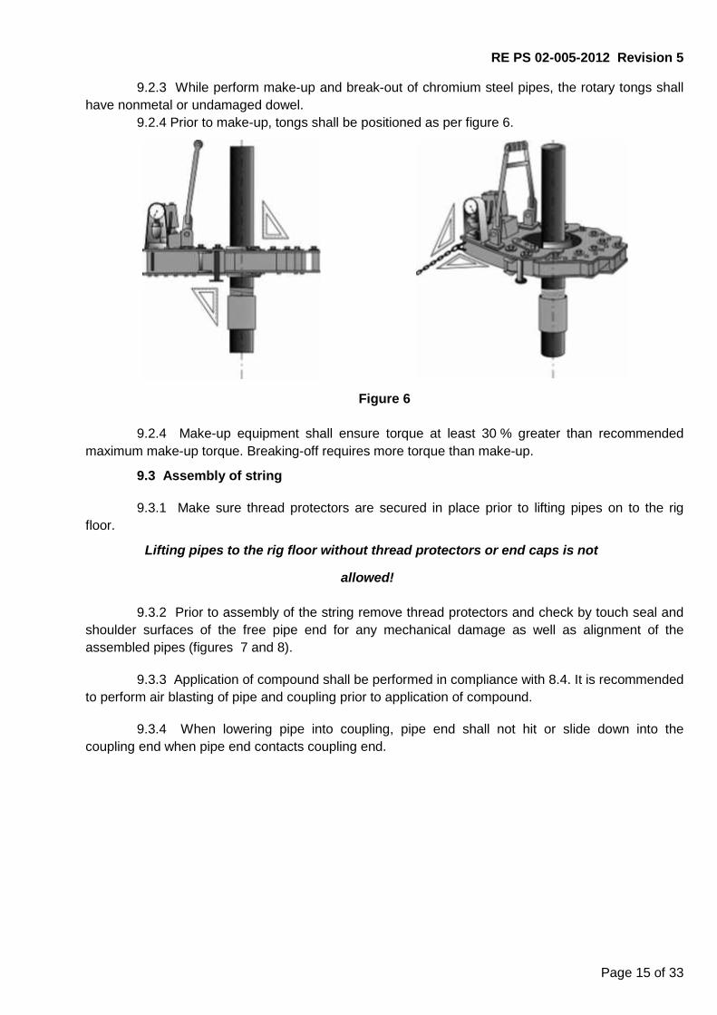
9.2.3 While perform make-up and break-out of chromium steel pipes, the rotary tongs shallhave nonmetal or undamaged dowel.
9.2.4 Prior to make-up, tongs shall be positioned as per figure 6.
Figure 6
9.2.4 Make-up equipment shall ensure torque at least 30 % greater than recommendedmaximum make-up torque. Breaking-off requires more torque than make-up.
9.3 Assembly of string
9.3.1 Make sure thread protectors are secured in place prior to lifting pipes on to the rigfloor.
Lifting pipes to the rig floor without thread protectors or end caps is not
allowed!
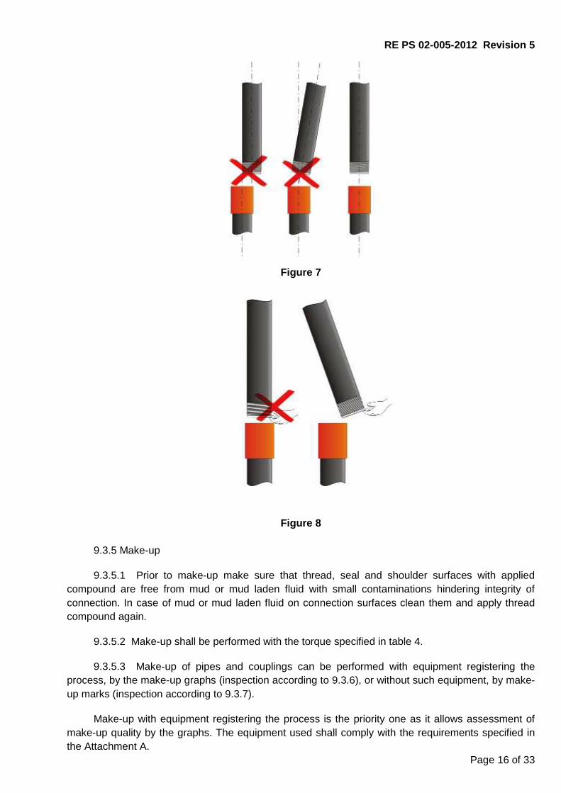
9.3.2 Prior to assembly of the string remove thread protectors and check by touch seal andshoulder surfaces of the free pipe end for any mechanical damage as well as alignment of theassembled pipes (figures 7 and 8).
9.3.3 Application of compound shall be performed in compliance with 8.4. It is recommendedto perform air blasting of pipe and coupling prior to application of compound.
9.3.4 When lowering pipe into coupling, pipe end shall not hit or slide down into thecoupling end when pipe end contacts coupling end.
RE PS 02-005-2012 Revision 5
Page 16 of 33
Figure 7
Figure 8
9.3.5 Make-up
9.3.5.1 Prior to make-up make sure that thread, seal and shoulder surfaces with appliedcompound are free from mud or mud laden fluid with small contaminations hindering integrity ofconnection. In case of mud or mud laden fluid on connection surfaces clean them and apply threadcompound again.
9.3.5.2 Make-up shall be performed with the torque specified in table 4.
9.3.5.3 Make-up of pipes and couplings can be performed with equipment registering theprocess, by the make-up graphs (inspection according to 9.3.6), or without such equipment, by make-up marks (inspection according to 9.3.7).
Make-up with equipment registering the process is the priority one as it allows assessment ofmake-up quality by the graphs. The equipment used shall comply with the requirements specified inthe Attachment A.

Page 17 of 33
Table 4
D, in S, inTorque, ft. lb. for steel grades
J55, K55 N80, L80 С90 R95,С95, T95 Р110 Q135Мmin Мopt Мmax Мmin Мopt Мmax Мmin Мopt Мmax Мmin Мopt Мmax Мmin Мopt Мmax Мmin Мopt Мmax
2 3/8
0,1902 1000 1000 1100 1200 1300 1500 1300 1500 1600 1400 1500 1700 1600 1800 1900 1700 1900 21000,2539 1100 1300 1400 1500 1600 1800 1600 1800 1900 1700 1900 2100 1900 2100 2400 2100 2400 26000,2949 1300 1400 1500 1600 1800 1900 1800 2000 2200 1800 2100 2300 2100 2300 2500 2400 2600 29000,3358 1300 1500 1600 1700 1900 2100 1900 2100 2400 2000 2200 2400 2300 2500 2700 2500 2800 3100
2 7/8
0,2169 1500 1600 1800 1800 2100 2300 2100 2300 2500 2200 2400 2700 2400 2700 3000 2700 3000 33000,2760 1700 1900 2100 2200 2400 2700 2400 2700 3000 2600 2900 3200 2900 3200 3500 3200 3600 40000,3079 1800 2000 2200 2400 2600 2900 2600 2900 3200 2700 3000 3300 3000 3400 3800 3400 3800 41000,3402 2000 2200 2400 2500 2800 3100 2800 3100 3400 2900 3200 3500 3300 3700 4100 3700 4100 46000,3921 2200 2400 2700 2800 3100 3400 3100 3500 3800 3200 3600 4000 3700 4100 4500 4100 4600 50000,4402 2400 2700 2900 3000 3400 3800 3400 3800 4100 3600 4000 4400 4000 4400 4900 4500 5000 5500
3 1/2
0,2161 2400 2700 2900 3000 3400 3800 3400 3800 4100 3600 4000 4400 4000 4400 4900 4500 5000 55000,2539 2600 2900 3200 3300 3700 4100 3700 4100 4600 3800 4300 4700 4400 4900 5400 4900 5500 60000,2890 2800 3100 3400 3600 4000 4400 4000 4400 4900 4200 4600 5100 4700 5200 5800 5200 5800 64000,3748 3200 3600 4000 4200 4600 5100 4600 5200 5700 4900 5500 6000 5500 6100 6700 6200 6900 75000,4299 3500 3900 4300 4500 5000 5500 5000 5600 6200 5200 5800 6400 5900 6600 7200 6600 7400 81000,4760 3800 4200 4600 4900 5400 5900 5400 6000 6600 5700 6300 6900 6300 7100 7800 7100 7900 87000,5299 4100 4500 4900 5200 5800 6400 5800 6500 7200 6100 6800 7400 6900 7600 8300 7700 8600 9400
4
0,2260 2700 2900 3200 3400 3800 4100 3800 4200 4600 4000 4400 4900 4400 4900 5500 5000 5500 61000,2618 2900 3200 3500 3800 4200 4600 4200 4600 5100 4400 4900 5500 5000 5500 6100 5600 6200 68000,3299 3500 3900 4300 4500 5000 5500 5000 5600 6200 5200 5800 6400 5900 6600 7200 6600 7400 81000,4150 4300 4700 5200 5500 6000 6600 6000 6700 7400 6300 7100 7800 7100 7900 8700 8000 8900 9800
4 1/2
0,2709 3000 3300 3700 3800 4200 4600 4200 4600 5100 4400 4800 5300 4700 5200 5800 5600 6200 68000,3370 3400 3800 4100 4400 4900 5500 4900 5500 6000 5000 5600 6200 5500 6100 6700 6500 7200 80000,3799 3800 4200 4600 5000 5600 6200 5500 6100 6700 5700 6300 7000 6300 6900 7600 7300 8100 89000,4299 4400 4800 5300 5700 6300 7000 6300 6900 7600 6400 7200 7900 7000 7800 8600 8300 9100 100000,5000 5000 5600 6200 6600 7400 8100 7200 8000 8800 7500 8300 9100 8200 9100 10000 9600 10600 11700
NOTE: Make-up with special-clearance couplings shall be performed using torque 20% less than the specified.
Page 18 of 33
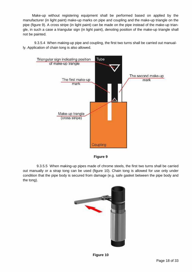
Make-up without registering equipment shall be performed based on applied by themanufacturer (in light paint) make-up marks on pipe and coupling and the make-up triangle on thepipe (figure 9). A cross stripe (in light paint) can be made on the pipe instead of the make-up trian-gle, in such a case a triangular sign (in light paint), denoting position of the make-up triangle shallnot be painted.
9.3.5.4 When making-up pipe and coupling, the first two turns shall be carried out manual-ly. Application of chain tong is also allowed.
Figure 9
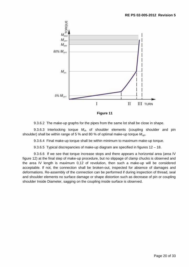
9.3.5.5 When making-up pipes made of chrome steels, the first two turns shall be carriedout manually or a strap tong can be used (figure 10). Chain tong is allowed for use only undercondition that the pipe body is secured from damage (e.g. safe gasket between the pipe body andthe tong).
Figure 10

RE PS 02-005-2012 Revision 5
Page 19 of 33
9.3.5.6 Rotation speed during connection make-up with the rotary tong shall correspond tothe values specified in Table 5.
Таble 5
Start of make-upEnd of make-up
(torqueing)First two revolutions Further revolu-tions
Speed maximum2 rev/min,
Better manually
High speed,But maximum
10 rev/min
Speed maximum2 rev/min
9.3.5.7 Even longitudinal movement of the pipe due to gradual increase of number ofengaged turns, shall be watched, significant warming of the connection (not more than 500 С overthe ambient temperature) shall not be allowed.
9.3.5.8 Make-up shall not cause significant mechanical damages like galling or jammingetc. on the pipe and coupling body.
The outer coupling surface shall be free of damages with depth more that 1% from the cou-pling nominal outside diameter.
Jamming marks from the tongs clamps are allowed on the pipe outer surface under conditionthe marks are not larger than 12,5% from the pipe wall thickness.
After make-up of chrome steel pipes the mark on the pipe body shall not be more than 0,008inch.
9.3.5.9 The final connection make-up torque shall be within Мmin to Мmax range.
9.3.5.10 Turning of coupling from the mill end is allowed when the maximum value of the fi-nal make-up torque (Мmax) is achieved, but maximum Lmax distance (table B.2). The final make-uptorque values shall be within Мmin to Мopt limits in order to reduce the possibility of the couplingturning.
If the turning of coupling exceeds Lmax, thread connection shall be disassembled, visuallyinspected; make sure there are no deformations of seal and shoulder elements and continuemake-up. Otherwise thread connection shall be rejected.
9.3.6 Thread connection make-up inspection by the make-up graph.
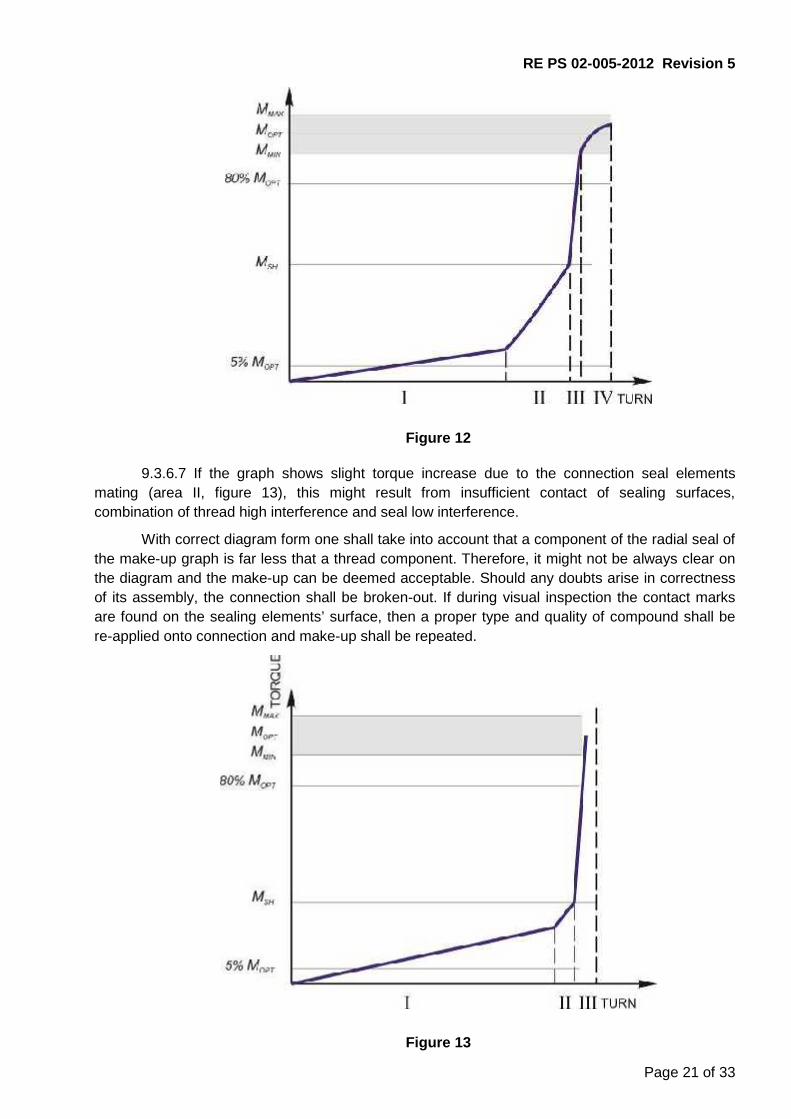
9.3.6.1 If the make-up is performed correctly and all the thread connection geometricalparameters comply with the requirements of the normative documentation, the make-up graph willshow defined areas which correspond to torque increase due to thread surfaces mating (area I),and the further mating of sealing and shoulder elements of the connection (area II and area III), asshown in the figure 11 below.
The rotary torque increase on the first two revolutions corresponding to the initial mating ofthread surfaces shall be smooth and even. Further on with mating of the thread surfaces and ofsealing elements of the connection, acceleration of rotary torque increase till shouldering of theconnection shall take place. The shouldering shall be accompanied with the sharp increase intorque, which confirms that make-up is performed correctly.
Depending on the power tong used and its adjustment, the make-up graph (especiallyarea I) can show areas with insignificant deviation from straight line: waves, leaps, etc. Suchdeviations shall be deemed acceptable if general view of the make-up graph corresponds to theestablished requirements.
RE PS 02-005-2012 Revision 5
Page 20 of 33
Figure 11
9.3.6.2 The make-up graphs for the pipes from the same lot shall be close in shape.
9.3.6.3 Interlocking torque Мsh of shoulder elements (coupling shoulder and pinshoulder) shall be within range of 5 % and 80 % of optimal make-up torque Мopt.
9.3.6.4 Final make-up torque shall be within minimum to maximum make-up torque.
9.3.6.5 Typical discrepancies of make-up diagram are specified in figures 12 – 18.
9.3.6.6 If we see that torque increase stops and there appears a horizontal area (area IVfigure 12) at the final step of make-up procedure, but no slippage of clamp chucks is observed andthe area IV length is maximum 0,12 of revolution, then such a make-up will be consideredacceptable. If not, the connection shall be broken-out, inspected for absence of damages anddeformations. Re-assembly of the connection can be performed if during inspection of thread, sealand shoulder elements no surface damage or shape distortion such as decrease of pin or couplingshoulder Inside Diameter, sagging on the coupling inside surface is observed.
RE PS 02-005-2012 Revision 5
Page 21 of 33
Figure 12
9.3.6.7 If the graph shows slight torque increase due to the connection seal elementsmating (area II, figure 13), this might result from insufficient contact of sealing surfaces,combination of thread high interference and seal low interference.
With correct diagram form one shall take into account that a component of the radial seal ofthe make-up graph is far less that a thread component. Therefore, it might not be always clear onthe diagram and the make-up can be deemed acceptable. Should any doubts arise in correctnessof its assembly, the connection shall be broken-out. If during visual inspection the contact marksare found on the sealing elements’ surface, then a proper type and quality of compound shall bere-applied onto connection and make-up shall be repeated.
Figure 13
RE PS 02-005-2012 Revision 5
Page 22 of 33
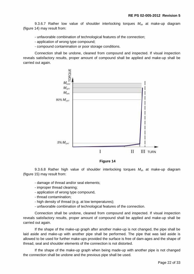
9.3.6.7 Rather low value of shoulder interlocking torques Мsh at make-up diagram(figure 14) may result from:
- unfavorable combination of technological features of the connection;- application of wrong type compound;- compound contamination or poor storage conditions.
Connection shall be undone, cleaned from compound and inspected. If visual inspectionreveals satisfactory results, proper amount of compound shall be applied and make-up shall becarried out again.
Figure 14
9.3.6.8 Rather high value of shoulder interlocking torques Мsh at make-up diagram(figure 15) may result from:
- damage of thread and/or seal elements;- improper thread cleaning;- application of wrong type compound,- thread contamination;- high density of thread (e.g. at low temperatures);- unfavorable combination of technological features of the connection.
Connection shall be undone, cleaned from compound and inspected. If visual inspectionreveals satisfactory results, proper amount of compound shall be applied and make-up shall becarried out again.
If the shape of the make-up graph after another make-up is not changed, the pipe shall belaid aside and make-up with another pipe shall be performed. The pipe that was laid aside isallowed to be used for further make-ups provided the surface is free of dam-ages and the shape ofthread, seal and shoulder elements of the connection is not distorted.
If the shape of the make-up graph when being made-up with another pipe is not changedthe connection shall be undone and the previous pipe shall be used.

RE PS 02-005-2012 Revision 5
Page 23 of 33
Figure 15
9.3.6.9 Leaps in the make-up diagram (figure 16) may result from:
- uneven application of compound and improper cleaning from preservative compound;- tongs jam;- uneven torque of torqueing.
Connection shall be undone, cleaned from compound and inspected. If visual inspectionreveals satisfactory results, proper amount of compound shall be applied and make-up shall becarried out again.
If the shape of the make-up graph after another make-up is not changed, the pipe shall belaid aside and make-up with another pipe shall be performed. The pipe that was laid aside isallowed to be used for further make-ups provided the surface is free of dam-ages and the shape ofthread, seal and shoulder elements of the connection is not distorted.
If the shape of the make-up graph when being made-up with another pipe is not changedthe connection shall be undone and the previous pipe shall be used.

RE PS 02-005-2012 Revision 5
Page 24 of 33
Figure 16
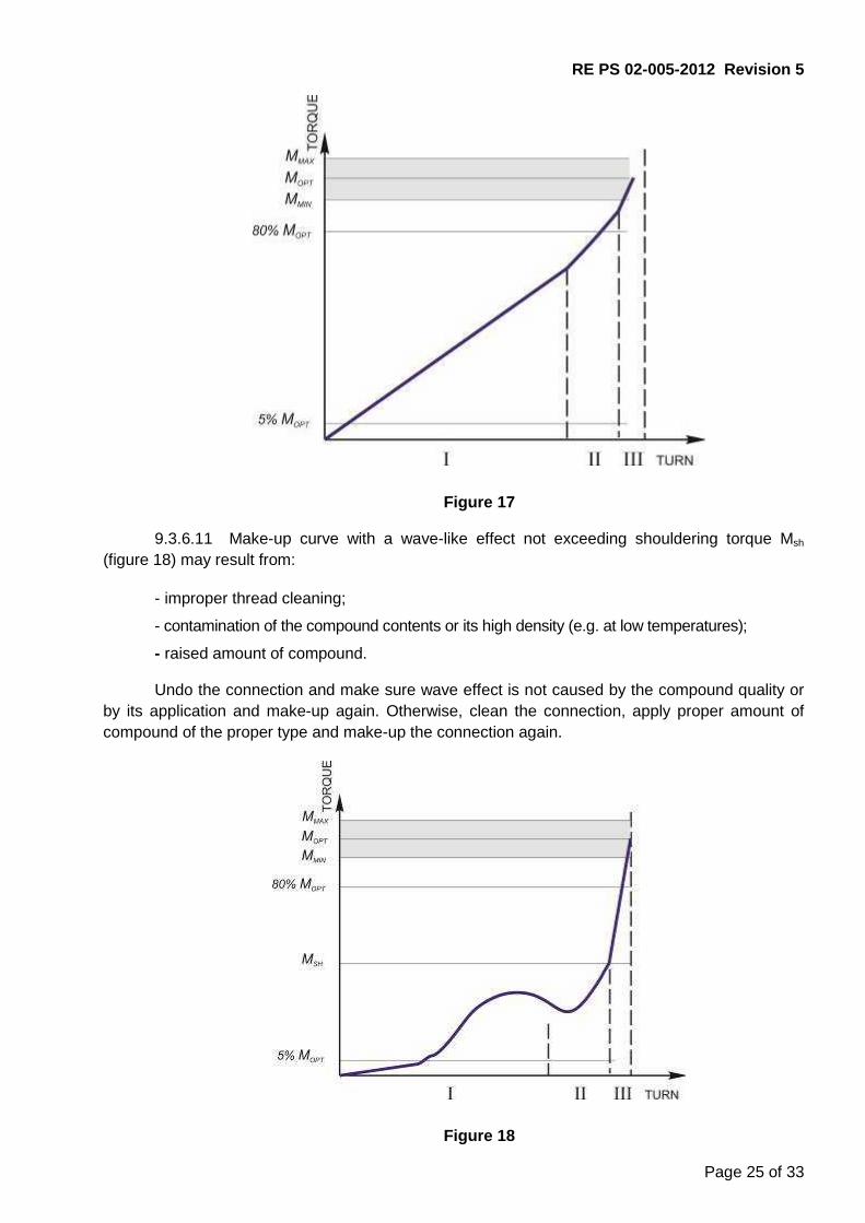
9.3.6.10 Make-up curve without clear shouldering torque Мsh (figure 17) may result from:
- thread damage;- improper thread cleaning;- unfavorable combination of interlocking features.
Connection shall be undone, cleaned from compound and inspected. If visual inspectionreveals satisfactory results, proper amount of compound shall be applied and make-up shall becarried out again.
If the shape of the make-up graph after another make-up is not changed, the pipe shall belaid aside and make-up with another pipe shall be performed. The pipe that was laid aside isallowed to be used for further make-ups provided the surface is free of dam-ages and the shape ofthread, seal and shoulder elements of the connection is not distorted.
If the shape of the make-up graph when being made-up with another pipe is not changedthe connection shall be undone and the previous pipe shall be used.
RE PS 02-005-2012 Revision 5
Page 25 of 33
Figure 17
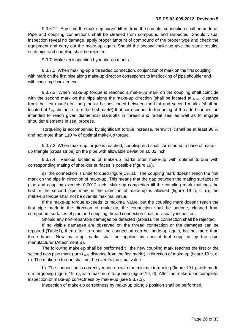
9.3.6.11 Make-up curve with a wave-like effect not exceeding shouldering torque Мsh
(figure 18) may result from:
- improper thread cleaning;
- contamination of the compound contents or its high density (e.g. at low temperatures);
- raised amount of compound.
Undo the connection and make sure wave effect is not caused by the compound quality orby its application and make-up again. Otherwise, clean the connection, apply proper amount ofcompound of the proper type and make-up the connection again.
Figure 18
RE PS 02-005-2012 Revision 5
Page 26 of 33
9.3.6.12 Any time the make-up curve differs from the sample, connection shall be undone.Pipe and coupling connections shall be cleaned from compound and inspected. Should visualinspection reveal no damage, apply proper amount of compound of the proper type and check theequipment and carry out the make-up again. Should the second make-up give the same results,such pipe and coupling shall be rejected.
9.3.7 Make-up inspection by make-up marks.
9.3.7.1 When making-up a threaded connection, conjunction of mark on the first couplingwith mark on the first pipe along make-up direction corresponds to interlocking of pipe shoulder endwith coupling shoulder end.
9.3.7.2 When make-up torque is reached a make-up mark on the coupling shall coincidewith the second mark on the pipe along the make-up direction (shall be located at Lmax distancefrom the first mark*) on the pipe or be positioned between the first and second marks (shall belocated at Lmin distance from the first mark*) that corresponds to torqueing of threaded connectionintended to reach given diametrical standoffs in thread and radial seal as well as to engageshoulder elements in seal process.
Torqueing is accompanied by significant torque increase, herewith it shall be at least 90 %and not more than 110 % of optimal make-up torque.
9.3.7.3 When make-up torque is reached, coupling end shall correspond to base of make-up triangle (cross stripe) on the pipe with allowable deviation ±0,02 inch.
9.3.7.4 Various locations of make-up marks after make-up with optimal torque withcorresponding mating of shoulder surfaces is possible (figure 19).
а) the connection is undertorqued (figure 19, а). The coupling mark doesn’t reach the firstmark on the pipe in direction of make-up. This means that the gap between the mating surfaces ofpipe and coupling exceeds 0,0012 inch. Make-up completion till the coupling mark matches thefirst or the second pipe mark in the direction of make-up is allowed (figure 19 b, c, d), themake-up torque shall not be over its maximal value.
If the make-up torque exceeds its maximal value, but the coupling mark doesn’t reach thefirst pipe mark in the direction of make-up, the connection shall be undone, cleaned fromcompound, surfaces of pipe and coupling thread connection shall be visually inspected.
Should any non-reparable damages be detected (table1), the connection shall be rejected.If no visible damages are observed on the thread connection or the damages can be
repaired (Table1), then after its repair the connection can be made-up again, but not more thanthree times. New make-up marks shall be applied by special tool supplied by the pipemanufacturer (Attachment B).
The following make-up shall be performed till the new coupling mark reaches the first or thesecond new pipe mark (turn Lmax distance from the first mark*) in direction of make-up (figure 19 b, c,d). The make-up torque shall not be over its maximal value.
b) The connection is correctly made-up with the minimal torqueing (figure 19 b), with medi-um torqueing (figure 19, c), with maximum torqueing (figure 19, d). After the make-up is complete,inspection of make-up correctness by make-up (see 9.3.7.3).
Inspection of make-up correctness by make-up triangle position shall be performed.

RE PS 02-005-2012 Revision 5
Page 27 of 33
c) The connection is overtorqued (figure 19, e). The coupling mark is located behind thesecond pipe mark (the distance between the coupling mark and the first pipe mark in direction ofmake-up is larger than Lmax*), which means possible deformation of mating sealing surfaces of pipegroove and coupling bore. In such a case the following shall be done:
Inspect coupling location relative to make-up triangle. If the coupling end face alignswith the triangular base, the coupling mark corresponds to the second pipe mark (figure19, d), and Lmax distance is exceeded by maximum 12 mm, the connection can be ac-cepted. If the coupling mark is behind the second pipe mark (figure 19 e), and Lmax dis-tance is exceeded by more than 12 mm, the connection shall be rejected;
The connection shall be undone, cleaned from compound and inspected. If deformationof sealing surfaces of pipe groove and coupling bore is not observed, new make-upmarks shall be applied by special tool supplied by the pipe manufacturer. Repeat theconnection make-up till the new coupling mark aligns the first or the second new pipemark in direction of make-up (figure 19 b, c, d). The make-up torque shall not be overits maximal value.
If deformation of sealing surfaces of pipe groove and coupling bore is observed, theconnection shall be rejected. The actual applied make-up torque value shall be checked, and theoptimal torque value can be reduced, if necessary.
* For the case, when there is only one mark on the pipe after restoration.

RE PS 02-005-2012 Revision 5
Page 28 of 33
Figure 19

RE PS 02-005-2012 Revision 5
Page 29 of 33
9.4 Disassembly of string9.4.1 When the string is being pulled out of the well, pipe ends are not allowed to hit
against coupling ends.
9.4.2 Break-out
9.4.2.1 Longitudinal even movement of the pipe due to gradual increase of number of en-gaged turns, shall be watched when the connection is disassembled.
9.4.2.2 The tongs shall be adjusted as shown in the figure 6 prior to break-out.
9.4.2.3 Break-out torque shall provide for the connection break-out.
9.4.2.4 Speed of connection break-out by rotary tong shall correspond to the ones, speci-fied in table 6.
Тable 6
Break-out startBreak-out finish
First two turns Further turns
Speed maximum2 rev/min,
High speed butmaximum10 rev/min
Speed maximum2 rev/min
9.4.2.5 Break-out shall not cause significant mechanical damages like galling or jammingetc. on the pipe and coupling body.
The outer coupling surface shall be free of damages with depth more that 1 % from thecoupling nominal Outer Diameter.
Jamming marks from the tongs clamps are allowed on the pipe outer surface under condi-tion the marks are not larger than 12,5% from the pipe wall thickness.
After make-up of chrome steel pipes and corrosion-proof steel pipes the mark on the pipebody shall not be more than 0,008 inch.
9.4.3 When the string is disassembled immediately after break-out thread protective ele-ments shall be installed onto pipe and coupling ends.
9.4.4 To store used pipes after string disassembly, if necessary, following preparationsshall be carried out:
- visual inspection of thread protectors damage;- visual inspection of thread protectors, pipes and couplings for significant mechanic dam-
age (like galls, jamming etc.) (see 7.1.2);- cleaning thread connections from compound and contaminations (see 7.1.4);- visual inspection of thread, seal and shoulder surfaces of pipes and couplings
(see 7.1.6). In case of any discrepancies repair as per Table 1 or reject the pipes;- cleaning thread protectors from previous compound and contaminations (see 7.1.4);- application of preservation compound (like Kendex OCTG, Total Jet Marine, EONFILM
300 Thread Protection Compound or equivalent) or preservative thread compound onto pipe andcoupling thread connections and installation of thread protectors.
10 Manufacturer’s warranty
Subject to strict compliance herewith ТМК UP РF threaded connection shall withstand atleast 9 make-and-break cycles with same performance.
RE PS 02-005-2012 Revision 5
Page 30 of 33
Attachment А(mandatory)
Equipment for make-up registration
ТМК UP РF threaded connection shall be made-up using equipment for record-keeping andsaving make-up diagram (make-up curve) in graphic or electronic type.
The curve is plotted based on torque values along vertical axis and number of turns alonghorizontal axis in linear scale. Only two last turns shall be displayed as torque in-creases attorqueing.
Using a computer make-up diagram shall be as follows:- Sufficient resolution (at least 800 × 600 pixels) for precise curve display. Display shall be
at least 9,8425 inch in diagonal, herewith make-up curve shall take at least 80 % of dis-play.- Display of minimum and maximum torque by horizontal lines (if required, optimal torque
shall be displayed).- Display of minimum and maximum interlocking torque of shoulder elements by horizontal
lines.- Automatic and manual determination of interlocking torque of connection shoulder
elements.- Display of rig floor number at each make-up.- Display of date and time of each make-up.- Availability of comments.- Display of Client name, well number, pipe diameter, weight, steel grade, type of threaded
connection, thread compound data and pipe manufacturer.- When applicable, mapping of latest make-up curve over diagrams of previous
successful make-ups.- When applicable, display of make-up speed in rpm, either on the make-up curve or on a
separate graph.Displayed make-up results shall not be sufficient for acceptance or rejection of make-up
operations. Correctness of make-up shall be confirmed by a competent specialist.
Prior to running the casing downhole, the calibration certificate shall be checked with latestand planned equipment calibration dates!

Page 31 of 33
Attachment B(mandatory)
Restoration of make-up marks and cross stripe, substitutive make-up triangle
B.1 When the tubes used repeatedly, make-up marks painted on the connection as well ascross stripe, applied to substitute the make-up triangle, may come off. In such case they shall berestored.
B.2 Cross stripe shall be made in permanent light paint. It shall be 0,4 inch wide, 3 inch longand it shall be applied at А1 distance from tube end face (figure B.1 and table B.1).
А1 – distance from the end face to painted cross strip.
Figure B.1 – Painted cross stripe positionТаble B.1
In inches
Pipe outer diameter, D Distance, А1 Limit deviation, А1
2 3/8 2,835
±0,0082 7/8 2,9333 1/2 3,232
4 3,5474 1/2 4,079
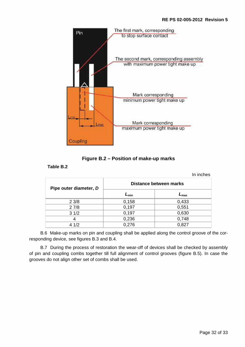
B.3 Make-up marks shall be made in permanent light paint on tube and coupling ends(figure B.2).
B.4 Make-up marks shall be restored by special devices – pin and coupling combs suppliedby the tubes manufacturer.
B.5 Combs shall be installed correspondingly onto pin and coupling threads and move themin direction of make-up till closure of shoulder surfaces of the devices with shoulder surfaces ofcorrespondingly pin and coupling. Herewith, no gap shall be allowed between the shoulder surfac-es of pin, coupling and device. Probe 0,0012 inch thick shall not pass along the entire joint perime-ter of these surfaces.
RE PS 02-005-2012 Revision 5
Page 32 of 33
Figure B.2 – Position of make-up marksТable B.2
In inches
Pipe outer diameter, DDistance between marks
Lmin Lmax
2 3/8 0,158 0,4332 7/8 0,197 0,5513 1/2 0,197 0,630
4 0,236 0,7484 1/2 0,276 0,827
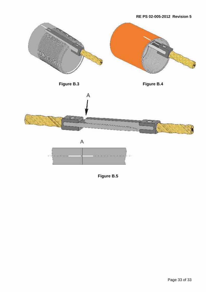
B.6 Make-up marks on pin and coupling shall be applied along the control groove of the cor-responding device, see figures B.3 and B.4.
B.7 During the process of restoration the wear-off of devices shall be checked by assemblyof pin and coupling combs together till full alignment of control grooves (figure B.5). In case thegrooves do not align other set of combs shall be used.
RE PS 02-005-2012 Revision 5
Page 33 of 33
Figure B.3 Figure B.4
Figure B.5