rdg: red hat openstack platform 16.1 versatile cloud for
TRANSCRIPT

RDG: Red Hat OpenStack Platform 16.1 Versatile Cloud for Packet and Data Processing with NVIDIA Network Hardware Acceleration.
Created on Mar 10, 2021
ScopeThis article is covering the full design, scale and deployment steps of the Red Hat considerationsOpenStack Platform cloud solution (Release 16.1) with NVIDIA hardware accelerated packet and data processing over highly available 100GbE fabric.
Abbreviations and Acronyms
Term Definition Term Definition
AI Artificial Intelligence MLAG Multi-Chassis Link Aggregation
ASAP2 Accelerated Switching and Packet Processing®
MLNX_OFED
NVIDIA Mellanox OpenFabrics Enterprise Distribution for Linux (network driver)
BGP Border Gateway Protocol NFV Network Functions Virtualization
BOM Bill of Materials NIC Network Interface Card
CPU Central Processing Unit OS Operating System
CUDA Compute Unified Device Architecture
OVS Open vSwitch
DHCP Dynamic Host Configuration Protocol
RDG Reference Deployment Guide
DPDK Data Plane Development Kit RDMA Remote Direct Memory Access
DVR Distributed Virtual Routing RHEL Red Hat Enterprise Linux
FW FirmWare RH-OSP Red Hat OpenStack Platform
GPU Graphics Processing Unit RoCE RDMA over Converged Ethernet
HA High Availability SDN Software Defined Networking
IP Internet Protocol SR-IOV Single Root Input/Output Virtualization
IPMI Intelligent Platform Management Interface
VF Virtual Function
L3 IP Network Layer 3 VF-LAG Virtual Function Link Aggregation
LACP Link Aggregation Control Protocol VLAN Virtual LAN
MGMT Management VM Virtual Machine
ML2 Modular Layer 2 Openstack Plugin
VNF Virtualized Network Function
IntroductionRed Hat OpenStack Platform ( ) is a cloud computing solution that enables the creation, RH-OSPdeployment, scale and management of a secure and reliable public or private OpenStack-based cloud. This production-ready platform offers a tight integration with NVIDIA networking and data processing technologies, and is used in this eference eployment uide ( ) to introduce a full deployment of a R D G RDG
and multi-tenant cloud.versatile highly-available
The solution demonstrated in this article can be easily applied to diverse use cases, such as orcore computing, with and processing, for NFV, Big Data and AI edge hardware accelerated packet data
workloads, over IP, DPDK and RoCE stacks.
Related Documents
QSG: NVIDIA BlueField DPU with OVS Hardware Offload.
RDG: RoCE accelerated vSphere 6.7 cluster deployment for ML and HPC workloads.
RDG: Red Hat OpenStack Platform 13 with NVIDIA Network OVS Offload.
QSG: TRex in a few steps using Nvidia ConnectX adapters.
QSG: ASAP² technology performance evaluation on Red Hat OpenStack Platform 13.
QSG: ASAP² OVS Acceleration Technology Performance Evaluation on RHEL Host.
QSG: Building Docker image with compiled Nvidia Network DPDK PMD.
How-to: Build and launch VM over OVS-DPDK v18.02 using Nvidia ConnectX adapters with DL-open linkage.
How-to: Configure PVRDMA in VMware vSphere 6.5/6.7.
RDG: Kubernetes Cluster Deployment for ML and HPC Workloads with NVIDIA GPU Virtualization and VMware PVRDMA Technologies.
RDG: OpenStack SMPTE 2110 Media Streaming Cloud with
NVIDIA Network Hardware Offload.
QSG: NVIDIA BlueField DPU with DPDK Acceleration.
RDG: NFVi Platform Based on Red Hat OSP13, Nuage Accelerated SDN and NVIDIA ConnectX-5 SmartNIC.
QSG: High Availability with Mellanox ASAP2 Enhanced SR-IOV (VF-LAG).
RDG: Apache Spark 3.0 on Kubernetes accelerated with RAPIDS over RoCE network.

ReferencesRed Hat OpenStack Platform 16.1 Installation Guide
Red Hat Openstack Platform 16.1 Spine Leaf Networking
Data Plane Development Kit (DPDK) Home
QSG: High Availability with ASAP2 Enhanced SR-IOV (VF-LAG).
Solution Architecture
Key Components and Technologies
accelerates diverse cloud workloads, including high-performance computing, NVIDIA T4 GPUdeep learning training and inference, machine learning, data analytics and graphics. Based on NVIDIA Turing™ architecture and packaged in an energy-efficient 70-watt, small PCIe form factor, T4 is optimized for mainstream computing environments, and features multi-precision Turing Tensor Cores and new RT Cores.
is a member of the world-class, award-winning ConnectX series of NVIDIA® ConnectX®-6 Dxnetwork adapters. ConnectX-6 Dx delivers two ports of 10/25/40/50/100Gb/s or a single-port of 200Gb/s Ethernet connectivity paired with best-in-class hardware capabilities that accelerate and secure cloud and data center workloads.
product family includes a broad portfolio of top-of-rack NVIDIA Spectrum® Ethernet Switchand aggregation switches, that can be deployed in layer-2 and layer-3 cloud designs, in overlay-based virtualized networks, or as part of high-performance, mission-critical ethernet storage fabrics.
product family of cables and transceivers provides the industry’s most complete NVIDIA LinkX®line of 10, 25, 40, 50, 100, 200, and 400GbE in Ethernet and EDR, HDR, and NDR in InfiniBand products for Cloud, HPC, Web 2.0, Enterprise, telco, storage and artificial intelligence and data center applications. LinkX cables and transceivers are often used to link top-of-rack switches downwards to network adapters in NVIDIA GPUs and CPU servers, and storage and/or upwards in switch-to-switch applications throughout the network infrastructure.
is the world’s most robust open networking operating system. It NVIDIA CUMULUS Linuxincludes a comprehensive list of advanced, modern networking features, and is built for scale.
is a cloud computing platform that virtualizes resources from Red Hat OpenStack Platformindustry-standard hardware, organizes those resources into clouds, and manages them so users can access what they need, when they need it.
(Data Plane Development Kit) is a set of libraries allowing to accelerate packet DPDKprocessing workloads, running on a wide variety of CPU architectures.
Logical Design
RH-OSP16.1 Release Notes
In Red Hat OpenStack Platform 16.1, the OVS switching function has been offloaded to the SmartNIC hardware. This enhancement reduces the processing resources required, and accelerates the datapath. In Red Hat OpenStack Platform 16.1, this feature has graduated from Technology Preview and is now fully supported.
Downloadable Content
All configuration files used in this article can be downloaded here: RDG_OSP16.1_Config_Files.zip
Network Fabric Design
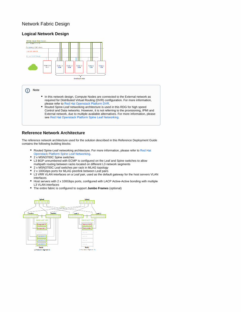
Logical Network Design
Reference Network Architecture
The reference network architecture used for the solution described in this Reference Deployment Guide contains the following building blocks:
Routed Spine-Leaf networking architecture. For more information, please refer to Red Hat .Openstack Platform Spine Leaf Networking
2 x MSN3700C Spine switchesL3 BGP unnumbered with ECMP is configured on the Leaf and Spine switches to allow multipath routing between racks located on different L3 network segments2 x MSN3700C Leaf switches per rack in MLAG topology2 x 100Gbps ports for MLAG peerlink between Leaf pairsL3 VRR VLAN interfaces on a Leaf pair, used as the default gateway for the host servers VLAN interfacesHost servers with 2 x 100Gbps ports, configured with LACP Active-Active bonding with multiple L3 VLAN interfacesThe entire fabric is configured to support (optional)Jumbo Frames
Note
In this network design, Compute Nodes are connected to the External network as required for Distributed Virtual Routing (DVR) configuration. For more information, please refer to .Red Hat Openstack Platform DVRRouted Spine-Leaf networking architecture is used in this RDG for high speed Control and Data networks. However, it is not referring to the provisioning, IPMI and External network, due to multiple available alternatives. For more information, please see .Red Hat Openstack Platform Spine Leaf Networking
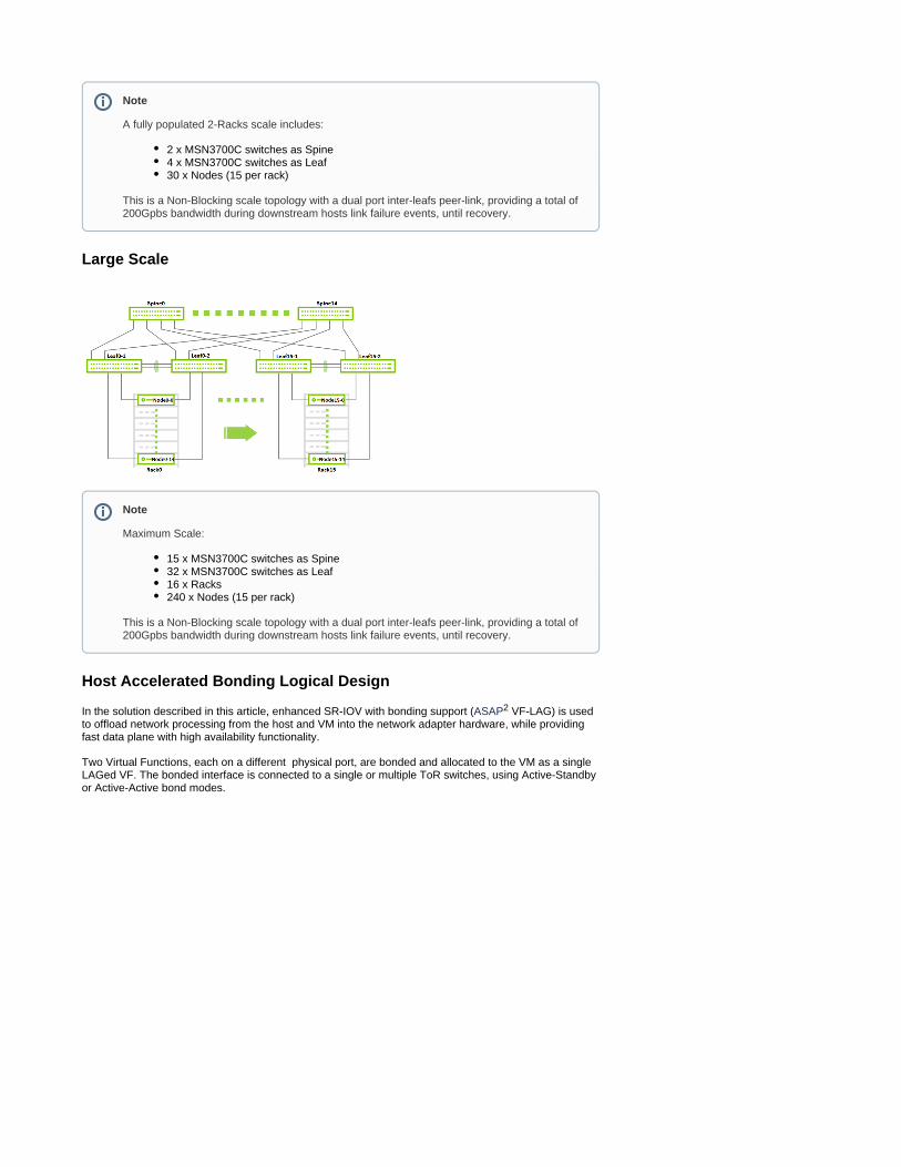
Large Scale
Host Accelerated Bonding Logical Design
In the solution described in this article, enhanced SR-IOV with bonding support ( VF-LAG) is used ASAP2 to offload network processing from the host and VM into the network adapter hardware, while providing fast data plane with high availability functionality.
Two Virtual Functions, each on a different physical port, are bonded and allocated to the VM as a single LAGed VF. The bonded interface is connected to a single or multiple ToR switches, using Active-Standby or Active-Active bond modes.
Note
A fully populated 2-Racks scale includes:
2 x MSN3700C switches as Spine4 x MSN3700C switches as Leaf30 x Nodes (15 per rack)
This is a Non-Blocking scale topology with a dual port inter-leafs peer-link, providing a total of 200Gpbs bandwidth during downstream hosts link failure events, until recovery.
Note
Maximum Scale:
15 x MSN3700C switches as Spine32 x MSN3700C switches as Leaf16 x Racks240 x Nodes (15 per rack)
This is a Non-Blocking scale topology with a dual port inter-leafs peer-link, providing a total of 200Gpbs bandwidth during downstream hosts link failure events, until recovery.
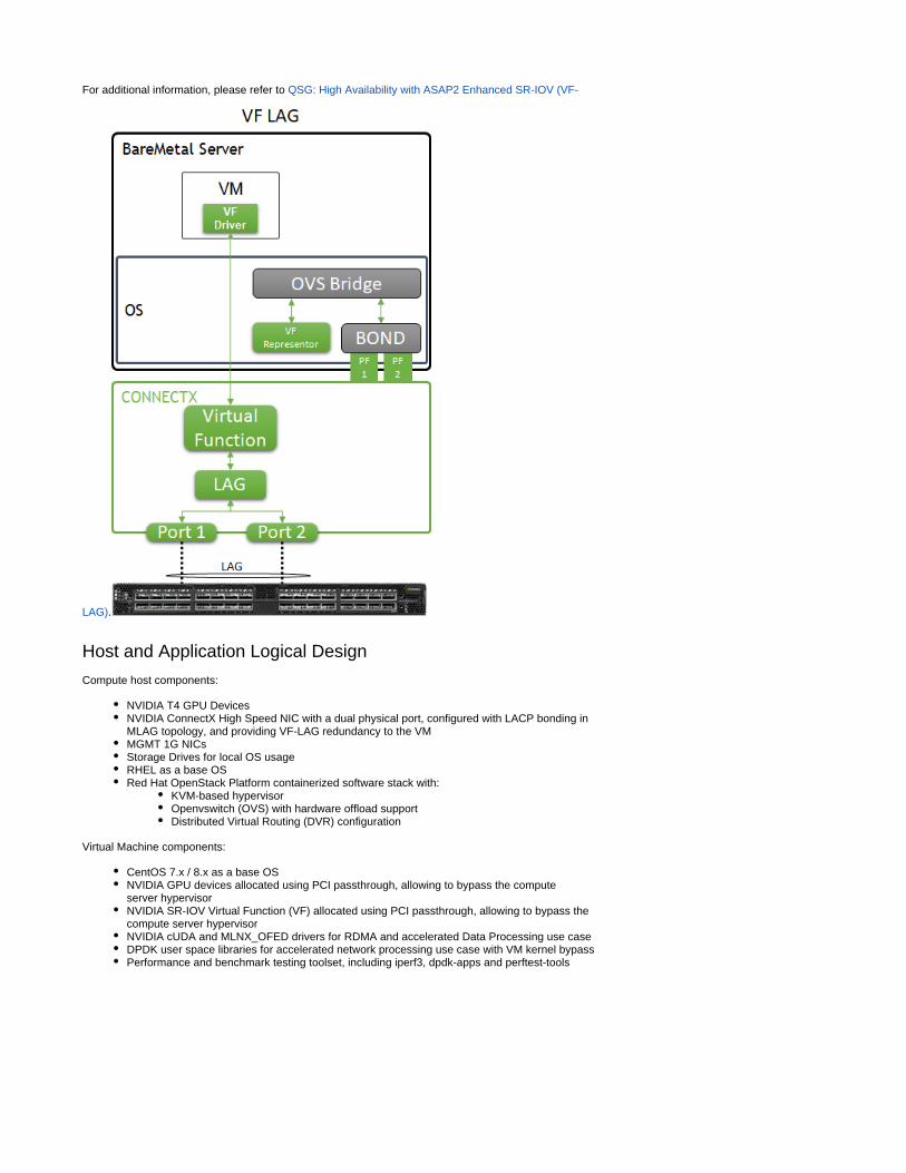
For additional information, please refer to QSG: High Availability with ASAP2 Enhanced SR-IOV (VF-
.LAG)
Host and Application Logical Design
Compute host components:
NVIDIA T4 GPU DevicesNVIDIA ConnectX High Speed NIC with a dual physical port, configured with LACP bonding in MLAG topology, and providing VF-LAG redundancy to the VMMGMT 1G NICsStorage Drives for local OS usageRHEL as a base OSRed Hat OpenStack Platform containerized software stack with:
KVM-based hypervisorOpenvswitch (OVS) with hardware offload supportDistributed Virtual Routing (DVR) configuration
Virtual Machine components:
CentOS 7.x / 8.x as a base OSNVIDIA GPU devices allocated using PCI passthrough, allowing to bypass the compute server hypervisorNVIDIA SR-IOV Virtual Function (VF) allocated using PCI passthrough, allowing to bypass the compute server hypervisorNVIDIA cUDA and drivers for RDMA and accelerated Data Processing use caseMLNX_OFEDDPDK user space libraries for accelerated network processing use case with VM kernel bypassPerformance and benchmark testing toolset, including iperf3, dpdk-apps and perftest-tools

Software Stack Components
Bill of Materials
Deployment and Configuration
Wiring

Network Fabric
NIC Firmware Upgrade and Settings
Please make sure to upgrade the nodes of the ConnectX NIC firmware to the latest release, as listed .here
In the following RDG, the RH-OSP cloud orchestration system is utilized to automatically upgrade the firmware of the compute and controller nodes during the cloud deployment process.
ConnectX First Boot cloud deployment file is used to point to a firmware file located on the undercloud node, and to make sure the firmware is updated on all nodes, in addition to setting required firmware parameters.
The full procedure is described in the Undercloud Director Preparation for Automatic NIC Firmware section below.Provisioning
Switch NOS Upgrade
Please make sure to upgrade Cumulus Linux to the latest release. Use the following links for further instructions and details regarding or Upgrading Cumulus Linux Installing a New Cumulus Linux Image.
Switch Configuration - Summary
Leaf Host Interfaces
Rack VLAN ID
Description Leaf Interfaces toward Hosts
MLAG MTU Leaf VRR Local IPs Leaf VRR VIP
Leaf VRR MAC
0 10 internal_api swp1-swp3, swp9-swp10
bond1-bond5
9216 172.17.0.252, 172.17.0.253
172.17.0.254
00:00:5E:00:01:00
0 20 storage swp1-swp3,swp9-swp10
bond1-bond5
9216 172.18.0.252, 172.18.0.253
172.18.0.254
00:00:5E:00:01:00
0 30 storage_mgmt
swp1-swp3,swp9-swp10
bond1-bond5
9216 172.19.0.252, 172.19.0.253
172.19.0.254
00:00:5E:00:01:00
0 40 tenant swp1-swp3,swp9-swp10
bond1-bond5
9216 172.16.0.252, 172.16.0.253
172.16.0.254
00:00:5E:00:01:00
1 11 internal_api swp9-swp10 bond4-bond5
9216 172.17.1.252, 172.17.1.253
172.17.1.254
00:00:5E:00:01:01
1 21 storage swp9-swp10 bond4-bond5
9216 172.18.1.252, 172.18.1.253
172.18.1.254
00:00:5E:00:01:01
Note
Use the same wiring to connect the undercloud node to the 1GbE switch.
Note
Starting from Cumulus Linux 4.2.0, the default password for the cumulus user account has changed to "cumulus", and must be changed upon first login.
Note
The tables in this section are aimed to explain the switches configurations and naming terminology used in the full configuration files.
For example in Leaf switch "Leaf0-1" which is located in Rack 0, VLANs 10 is configured on interfaces swp1-swp3 and swp9-swp10 which are members in BOND interfaces bond1-bond5 respectively (swp1 in bond1, swp10 in bond5) with MTU of 9126. VLAN 10 has VRR IP address of 172.17.0.252 on Leaf0-1 and of 172.17.0.253 on its MLAG peer switch "Leaf0-2" with a Virtual IP address of 172.17.0.254 and MAC address of 00:00:5E:00:01:00.
Detailed switch configuration can be found in the next sections and the tables below are introduced as a complementory visual tool for the full configuration files.

1 31 storage_mgmt
swp9-swp10 bond4-bond5
9216 172.19.1.252, 172.19.1.253
172.19.1.254
00:00:5E:00:01:01
1 41 tenant swp9-swp10 bond4-bond5
9216 172.16.1.252, 172.16.1.253
172.16.1.254
00:00:5E:00:01:01
Leaf Peerlink Interfaces
Rack VLAN ID Description Leaf Interfaces Local Peerlink IP System MAC
0 4094 Peerlink swp15-swp16 10.10.10.1 44:38:39:BE:EF:AA
0 4094 Peerlink swp15-swp16 10.10.10.2 44:38:39:BE:EF:AA
1 4094 Peerlink swp15-swp16 10.10.10.3 44:38:39:BE:EF:BB
1 4094 Peerlink swp15-swp16 10.10.10.4 44:38:39:BE:EF:BB
Leaf-Spine Interfaces
Rack Leaf Leaf Interfaces Spine0 Interface Spine1 Interface MTU
0 1 swp31, swp32 swp13 swp13 9216
0 2 swp31, swp32 swp14 swp14 9216
1 1 swp31, swp32 swp15 swp15 9216
1 2 swp31, swp32 swp16 swp16 9216
Switch Interface Topology
Switch Configuration - Detailed
Interfaces
Leaf0-1
/etc/network/interfaces
#source /etc/network/interfaces.d/*.intf
auto loiface lo inet loopback address 10.10.10.1/32
auto mgmtiface mgmt vrf-table auto address 127.0.0.1/8 address ::1/128
auto eth0iface eth0 inet dhcp vrf mgmt
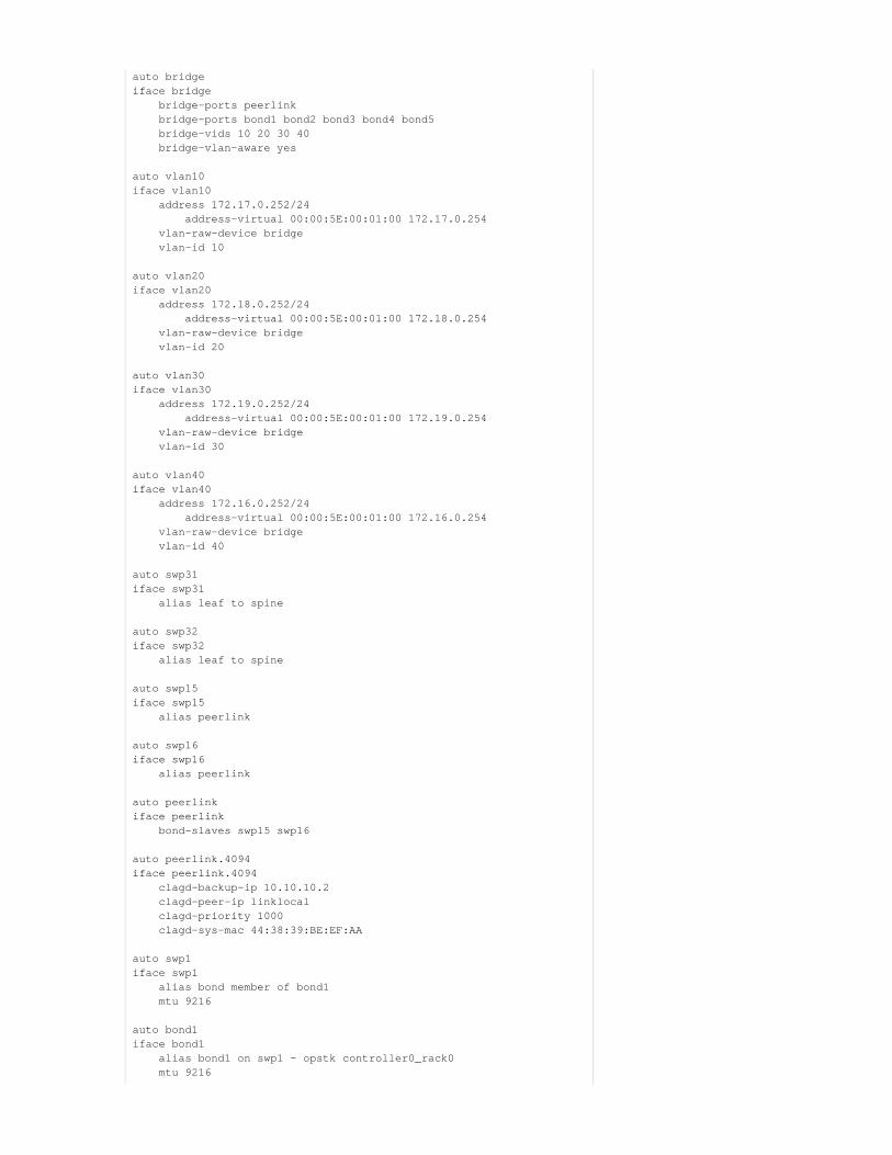
auto bridgeiface bridge bridge-ports peerlink bridge-ports bond1 bond2 bond3 bond4 bond5 bridge-vids 10 20 30 40 bridge-vlan-aware yes
auto vlan10iface vlan10 address 172.17.0.252/24 address-virtual 00:00:5E:00:01:00 172.17.0.254 vlan-raw-device bridge vlan-id 10
auto vlan20iface vlan20 address 172.18.0.252/24 address-virtual 00:00:5E:00:01:00 172.18.0.254 vlan-raw-device bridge vlan-id 20
auto vlan30iface vlan30 address 172.19.0.252/24 address-virtual 00:00:5E:00:01:00 172.19.0.254 vlan-raw-device bridge vlan-id 30
auto vlan40iface vlan40 address 172.16.0.252/24 address-virtual 00:00:5E:00:01:00 172.16.0.254 vlan-raw-device bridge vlan-id 40
auto swp31iface swp31 alias leaf to spine
auto swp32iface swp32 alias leaf to spine
auto swp15iface swp15 alias peerlink
auto swp16iface swp16 alias peerlink
auto peerlinkiface peerlink bond-slaves swp15 swp16
auto peerlink.4094iface peerlink.4094 clagd-backup-ip 10.10.10.2 clagd-peer-ip linklocal clagd-priority 1000 clagd-sys-mac 44:38:39:BE:EF:AA
auto swp1iface swp1 alias bond member of bond1 mtu 9216
auto bond1iface bond1 alias bond1 on swp1 - opstk controller0_rack0 mtu 9216
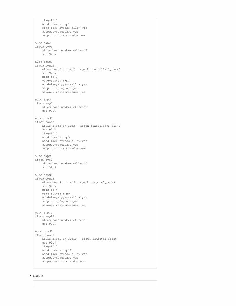
clag-id 1 bond-slaves swp1 bond-lacp-bypass-allow yes mstpctl-bpduguard yes mstpctl-portadminedge yes
auto swp2iface swp2 alias bond member of bond2 mtu 9216
auto bond2iface bond2 alias bond2 on swp2 - opstk controller1_rack0 mtu 9216 clag-id 2 bond-slaves swp2 bond-lacp-bypass-allow yes mstpctl-bpduguard yes mstpctl-portadminedge yes
auto swp3iface swp3 alias bond member of bond3 mtu 9216
auto bond3iface bond3 alias bond3 on swp3 - opstk controller2_rack0 mtu 9216 clag-id 3 bond-slaves swp3 bond-lacp-bypass-allow yes mstpctl-bpduguard yes mstpctl-portadminedge yes
auto swp9iface swp9 alias bond member of bond4 mtu 9216
auto bond4iface bond4 alias bond4 on swp9 - opstk compute0_rack0 mtu 9216 clag-id 4 bond-slaves swp9 bond-lacp-bypass-allow yes mstpctl-bpduguard yes mstpctl-portadminedge yes auto swp10iface swp10 alias bond member of bond5 mtu 9216
auto bond5iface bond5 alias bond5 on swp10 - opstk compute1_rack0 mtu 9216 clag-id 5 bond-slaves swp10 bond-lacp-bypass-allow yes mstpctl-bpduguard yes mstpctl-portadminedge yes
Leaf0-2

/etc/network/interfaces
#source /etc/network/interfaces.d/*.intf
auto loiface lo inet loopback address 10.10.10.2/32
auto mgmtiface mgmt vrf-table auto address 127.0.0.1/8 address ::1/128
auto eth0iface eth0 inet dhcp vrf mgmt
auto bridgeiface bridge bridge-ports peerlink bridge-ports bond1 bond2 bond3 bond4 bond5 bridge-vids 10 20 30 40 bridge-vlan-aware yes
auto vlan10iface vlan10 address 172.17.0.253/24 address-virtual 00:00:5E:00:01:00 172.17.0.254 vlan-raw-device bridge vlan-id 10
auto vlan20iface vlan20 address 172.18.0.253/24 address-virtual 00:00:5E:00:01:00 172.18.0.254 vlan-raw-device bridge vlan-id 20
auto vlan30iface vlan30 address 172.19.0.253/24 address-virtual 00:00:5E:00:01:00 172.19.0.254 vlan-raw-device bridge vlan-id 30
auto vlan40iface vlan40 address 172.16.0.253/24 address-virtual 00:00:5E:00:01:00 172.16.0.254 vlan-raw-device bridge vlan-id 40
auto swp31iface swp31 alias leaf to spine
auto swp32iface swp32 alias leaf to spine
auto swp15iface swp15 alias peerlink
auto swp16iface swp16 alias peerlink

auto peerlinkiface peerlink bond-slaves swp15 swp16
auto peerlink.4094iface peerlink.4094 clagd-backup-ip 10.10.10.1 clagd-peer-ip linklocal clagd-priority 1000
clagd-sys-mac 44:38:39:BE:EF:AA
auto swp1iface swp1 alias bond member of bond1 mtu 9216
auto bond1iface bond1 alias bond1 on swp1 - opstk controller0_rack0 mtu 9216 clag-id 1 bond-slaves swp1 bond-lacp-bypass-allow yes mstpctl-bpduguard yes mstpctl-portadminedge yes
auto swp2iface swp2 alias bond member of bond2 mtu 9216
auto bond2iface bond2 alias bond2 on swp2 - opstk controller1_rack0 mtu 9216 clag-id 2 bond-slaves swp2 bond-lacp-bypass-allow yes mstpctl-bpduguard yes mstpctl-portadminedge yes
auto swp3iface swp3 alias bond member of bond3 mtu 9216
auto bond3iface bond3 alias bond3 on swp3 - opstk controller2_rack0 mtu 9216 clag-id 3 bond-slaves swp3 bond-lacp-bypass-allow yes mstpctl-bpduguard yes mstpctl-portadminedge yes
auto swp9iface swp9 alias bond member of bond4 mtu 9216
auto bond4iface bond4 alias bond4 on swp9 - opstk compute0_rack0 mtu 9216 clag-id 4 bond-slaves swp9 bond-lacp-bypass-allow yes mstpctl-bpduguard yes mstpctl-portadminedge yes

auto swp10iface swp10 alias bond member of bond5 mtu 9216
auto bond5iface bond5 alias bond5 on swp10 - opstk compute1_rack0 mtu 9216 clag-id 5 bond-slaves swp10 bond-lacp-bypass-allow yes mstpctl-bpduguard yes mstpctl-portadminedge yes
Leaf1-1
/etc/network/interfaces
#source /etc/network/interfaces.d/*.intf
auto loiface lo inet loopback address 10.10.10.3/32
auto mgmtiface mgmt vrf-table auto address 127.0.0.1/8 address ::1/128
auto eth0iface eth0 inet dhcp vrf mgmt
auto bridgeiface bridge bridge-ports peerlink bridge-ports bond4 bond5 bridge-vids 11 21 31 41 bridge-vlan-aware yes
auto vlan11iface vlan11 address 172.17.1.252/24 address-virtual 00:00:5E:00:01:01 172.17.1.254 vlan-raw-device bridge vlan-id 11
auto vlan21iface vlan21 address 172.18.1.252/24 address-virtual 00:00:5E:00:01:01 172.18.1.254 vlan-raw-device bridge vlan-id 21
auto vlan31iface vlan31 address 172.19.1.252/24 address-virtual 00:00:5E:00:01:01 172.19.1.254 vlan-raw-device bridge vlan-id 31
auto vlan41iface vlan41 address 172.16.1.252/24
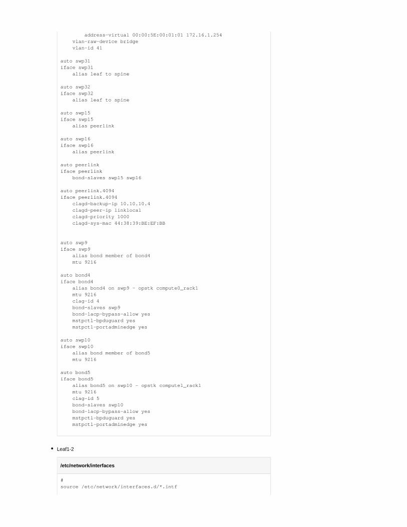
address-virtual 00:00:5E:00:01:01 172.16.1.254 vlan-raw-device bridge vlan-id 41
auto swp31iface swp31 alias leaf to spine
auto swp32iface swp32 alias leaf to spine
auto swp15iface swp15 alias peerlink
auto swp16iface swp16 alias peerlink
auto peerlinkiface peerlink bond-slaves swp15 swp16
auto peerlink.4094iface peerlink.4094 clagd-backup-ip 10.10.10.4 clagd-peer-ip linklocal clagd-priority 1000 clagd-sys-mac 44:38:39:BE:EF:BB
auto swp9iface swp9 alias bond member of bond4 mtu 9216
auto bond4iface bond4 alias bond4 on swp9 - opstk compute0_rack1 mtu 9216 clag-id 4 bond-slaves swp9 bond-lacp-bypass-allow yes mstpctl-bpduguard yes mstpctl-portadminedge yes auto swp10iface swp10 alias bond member of bond5 mtu 9216
auto bond5iface bond5 alias bond5 on swp10 - opstk compute1_rack1 mtu 9216 clag-id 5 bond-slaves swp10 bond-lacp-bypass-allow yes mstpctl-bpduguard yes mstpctl-portadminedge yes
Leaf1-2
/etc/network/interfaces
#source /etc/network/interfaces.d/*.intf

auto loiface lo inet loopback address 10.10.10.4/32
auto mgmtiface mgmt vrf-table auto address 127.0.0.1/8 address ::1/128
auto eth0iface eth0 inet dhcp vrf mgmt
auto bridgeiface bridge bridge-ports peerlink bridge-ports bond4 bond5 bridge-vids 11 21 31 41 bridge-vlan-aware yes
auto vlan11iface vlan11 address 172.17.1.253/24 address-virtual 00:00:5E:00:01:01 172.17.1.254 vlan-raw-device bridge vlan-id 11
auto vlan21iface vlan21 address 172.18.1.253/24 address-virtual 00:00:5E:00:01:01 172.18.1.254 vlan-raw-device bridge vlan-id 21
auto vlan31iface vlan31 address 172.19.1.253/24 address-virtual 00:00:5E:00:01:01 172.19.1.254 vlan-raw-device bridge vlan-id 31
auto vlan41iface vlan41 address 172.16.1.253/24 address-virtual 00:00:5E:00:01:01 172.16.1.254 vlan-raw-device bridge vlan-id 41
auto swp31iface swp31 alias leaf to spine
auto swp32iface swp32 alias leaf to spine
auto swp15iface swp15 alias peerlink
auto swp16iface swp16 alias peerlink
auto peerlinkiface peerlink bond-slaves swp15 swp16
auto peerlink.4094

iface peerlink.4094 clagd-backup-ip 10.10.10.3 clagd-peer-ip linklocal clagd-priority 1000 clagd-sys-mac 44:38:39:BE:EF:BB
auto swp9iface swp9 alias bond member of bond4 mtu 9216
auto bond4iface bond4 alias bond4 on swp9 - opstk compute0_rack1 mtu 9216 clag-id 4 bond-slaves swp9 bond-lacp-bypass-allow yes mstpctl-bpduguard yes mstpctl-portadminedge yes auto swp10iface swp10 alias bond member of bond5 mtu 9216
auto bond5iface bond5 alias bond5 on swp10 - opstk compute1_rack1 mtu 9216 clag-id 5 bond-slaves swp10 bond-lacp-bypass-allow yes mstpctl-bpduguard yes mstpctl-portadminedge yes
Spine0

/etc/network/interfaces
#source /etc/network/interfaces.d/*.intf
# The loopback network interfaceauto loiface lo inet loopback address 10.10.10.101/32
# The primary network interfaceauto eth0iface eth0 inet dhcp vrf mgmt
auto mgmtiface mgmt address 127.0.0.1/8 address ::1/128 vrf-table auto
auto swp13iface swp13 alias leaf to spine
auto swp14iface swp14 alias leaf to spine
auto swp15iface swp15 alias leaf to spine
auto swp16iface swp16 alias leaf to spine
Spine1
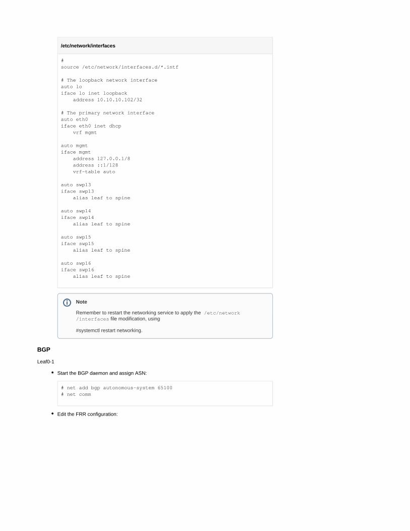
/etc/network/interfaces
#source /etc/network/interfaces.d/*.intf
# The loopback network interfaceauto loiface lo inet loopback address 10.10.10.102/32
# The primary network interfaceauto eth0iface eth0 inet dhcp vrf mgmt
auto mgmtiface mgmt address 127.0.0.1/8 address ::1/128 vrf-table auto
auto swp13iface swp13 alias leaf to spine
auto swp14iface swp14 alias leaf to spine
auto swp15iface swp15 alias leaf to spine
auto swp16iface swp16 alias leaf to spine
BGP
Leaf0-1
Start the BGP daemon and assign ASN:
# net add bgp autonomous-system 65100# net comm
Edit the FRR configuration:
Note
Remember to restart the networking service to apply the /etc/network file modification, using/interfaces
#systemctl restart networking.

/etc/frr/frr.conf
.
.
.log syslog informationalservice integrated-vtysh-configline vty
router bgp 65100 bgp router-id 10.10.10.1 bgp bestpath as-path multipath-relax neighbor underlay peer-group neighbor underlay remote-as external neighbor peerlink.4094 interface remote-as internal neighbor swp31 interface peer-group underlay neighbor swp32 interface peer-group underlay ! ! address-family ipv4 unicast redistribute connected exit-address-family !!
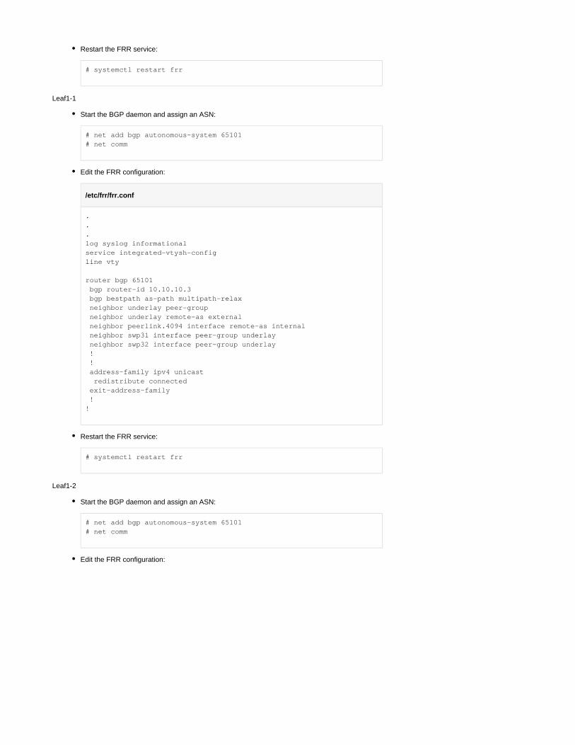
Restart the FRR service:
# systemctl restart frr
Leaf0-2
Start the BGP daemon, and assign ASN:
# net add bgp autonomous-system 65100# net comm
Edit the FRR configuration:
/etc/frr/frr.conf
.
.
.log syslog informationalservice integrated-vtysh-configline vty
router bgp 65100 bgp router-id 10.10.10.2 bgp bestpath as-path multipath-relax neighbor underlay peer-group neighbor underlay remote-as external neighbor peerlink.4094 interface remote-as internal neighbor swp31 interface peer-group underlay neighbor swp32 interface peer-group underlay ! ! address-family ipv4 unicast redistribute connected exit-address-family !!
Restart the FRR service:
# systemctl restart frr
Leaf1-1
Start the BGP daemon and assign an ASN:
# net add bgp autonomous-system 65101# net comm
Edit the FRR configuration:
/etc/frr/frr.conf
.
.
.log syslog informationalservice integrated-vtysh-configline vty
router bgp 65101 bgp router-id 10.10.10.3 bgp bestpath as-path multipath-relax neighbor underlay peer-group neighbor underlay remote-as external neighbor peerlink.4094 interface remote-as internal neighbor swp31 interface peer-group underlay neighbor swp32 interface peer-group underlay ! ! address-family ipv4 unicast redistribute connected exit-address-family !!
Restart the FRR service:
# systemctl restart frr
Leaf1-2
Start the BGP daemon and assign an ASN:
# net add bgp autonomous-system 65101# net comm
Edit the FRR configuration:

/etc/frr/frr.conf
.
.
.log syslog informationalservice integrated-vtysh-configline vty
router bgp 65101 bgp router-id 10.10.10.4 bgp bestpath as-path multipath-relax neighbor underlay peer-group neighbor underlay remote-as external neighbor peerlink.4094 interface remote-as internal neighbor swp31 interface peer-group underlay neighbor swp32 interface peer-group underlay ! ! address-family ipv4 unicast redistribute connected exit-address-family !!
Restart the FRR service:
# systemctl restart frr
Spine0
Start the BGP daemon and assign an ASN:
# net add bgp autonomous-system 65199# net comm
Edit the FRR configuration:
/etc/frr/frr.conf
.
.
.log syslog informationalservice integrated-vtysh-configline vty
router bgp 65199 bgp router-id 10.10.10.101 bgp bestpath as-path multipath-relax neighbor underlay peer-group neighbor underlay remote-as external neighbor swp13 interface peer-group underlay neighbor swp14 interface peer-group underlay neighbor swp15 interface peer-group underlay neighbor swp16 interface peer-group underlay ! ! address-family ipv4 unicast redistribute connected exit-address-family!
Restart the FRR service:
# systemctl restart frr
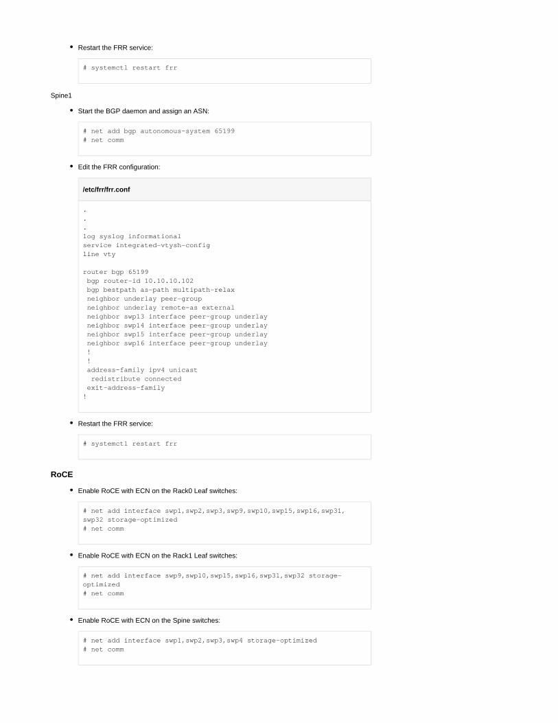
Spine1
Start the BGP daemon and assign an ASN:
# net add bgp autonomous-system 65199# net comm
Edit the FRR configuration:
/etc/frr/frr.conf
.
.
.log syslog informationalservice integrated-vtysh-configline vty
router bgp 65199 bgp router-id 10.10.10.102 bgp bestpath as-path multipath-relax neighbor underlay peer-group neighbor underlay remote-as external neighbor swp13 interface peer-group underlay neighbor swp14 interface peer-group underlay neighbor swp15 interface peer-group underlay neighbor swp16 interface peer-group underlay ! ! address-family ipv4 unicast redistribute connected exit-address-family!
Restart the FRR service:
# systemctl restart frr
RoCE
Enable RoCE with ECN on the Rack0 Leaf switches:
# net add interface swp1,swp2,swp3,swp9,swp10,swp15,swp16,swp31,swp32 storage-optimized# net comm
Enable RoCE with ECN on the Rack1 Leaf switches:
# net add interface swp9,swp10,swp15,swp16,swp31,swp32 storage-optimized# net comm
Enable RoCE with ECN on the Spine switches:
# net add interface swp1,swp2,swp3,swp4 storage-optimized# net comm

Verification
Confirm the interfaces status on the Leaf switches. Make sure all interfaces are UP and configured with the correct MTU. Verify the correct LLDP neighbours:
# net show intState Name Spd MTU Mode LLDP Summary----- ------------- ---- ----- ------------- -------------------------- -------------------------UP lo N/A 65536 Loopback IP: 127.0.0.1/8 lo IP: 10.10.10.1/32 lo IP: ::1/128UP eth0 1G 1500 Mgmt (40) Master: mgmt(UP) eth0 IP: /24(DHCP)UP swp1 100G 9216 BondMember Master: bond1(UP)UP swp2 100G 9216 BondMember Master: bond2(UP)UP swp3 100G 9216 BondMember Master: bond3(UP)UP swp9 100G 9216 BondMember Master: bond4(UP)UP swp10 100G 9216 BondMember Master: bond5(UP)UP swp15 100G 9216 BondMember Leaf0-2 (swp15) Master: peerlink(UP)UP swp16 100G 9216 BondMember Leaf0-2 (swp16) Master: peerlink(UP)UP swp31 100G 9216 Default Spine0 (swp15)UP swp32 100G 9216 Default Spine1 (swp15)UP bond1 100G 9216 802.3ad Master: bridge(UP) bond1 Bond Members: swp1(UP)UP bond2 100G 9216 802.3ad Master: bridge(UP) bond2 Bond Members: swp2(UP)UP bond3 100G 9216 802.3ad Master: bridge(UP) bond3 Bond Members: swp3(UP)UP bond4 100G 9216 802.3ad Master: bridge(UP) bond4 Bond Members: swp9(UP)UP bond5 100G 9216 802.3ad Master: bridge(UP) bond5 Bond Members: swp10(UP)UP bridge N/A 9216 Bridge/L2UP mgmt N/A 65536 VRF IP: 127.0.0.1/8 mgmt IP: ::1/128UP peerlink 200G 9216 802.3

ad Master: bridge(UP) peerlink Bond Members: swp15(UP) peerlink Bond Members: swp16(UP)UP peerlink.4094 200G 9216 BGPUnnumberedUP vlan10 N/A 9216 Interface/L3 IP: 172.17.0.252/24UP vlan10-v0 N/A 9216 Interface/L3 IP: 172.17.0.254/32UP vlan20 N/A 9216 Interface/L3 IP: 172.18.0.252/24UP vlan20-v0 N/A 9216 Interface/L3 IP: 172.18.0.254/32UP vlan30 N/A 9216 Interface/L3 IP: 172.19.0.252/24UP vlan30-v0 N/A 9216 Interface/L3 IP: 172.19.0.254/32UP vlan40 N/A 9216 Interface/L3 IP: 172.16.0.252/24UP vlan40-v0 N/A 9216 Interface/L3 IP: 172.16.0.254/32
Confirm the MLAG status on the Leaf switches. Verify the backup IP is active, and make sure there are no conflicts or Proto-Down:
# net show clagThe peer is alive Our Priority, ID, and Role: 1000 b8:59:9f:a7:b4:20 secondary Peer Priority, ID, and Role: 1000 b8:59:9f:a7:b3:20 primary Peer Interface and IP: peerlink.4094 fe80::ba59:9fff:fea7:b320 (linklocal) Backup IP: 10.10.10.2 (active) System MAC: 44:38:39:be:ef:aa
CLAG InterfacesOur Interface Peer Interface CLAG Id Conflicts Proto-Down Reason---------------- ---------------- ------- -------------------- ----------------- bond4 bond4 4 - - bond5 bond5 5 - - bond1 bond1 1 - - bond2 bond2 2 - - bond3 bond3 3 - -
Confirm the BGP neighbors discovery on all switches:

# net show bgp summaryshow bgp ipv4 unicast summary=============================BGP router identifier 10.10.10.1, local AS number 65100 vrf-id 0BGP table version 136RIB entries 35, using 6720 bytes of memoryPeers 3, using 64 KiB of memoryPeer groups 1, using 64 bytes of memory
Neighbor V AS MsgRcvd MsgSent TblVer InQ OutQ Up/Down State/PfxRcdSpine0(swp31) 4 65199 34611 34624 0 0 0 00:56:52 11Spine1(swp32) 4 65199 34615 34631 0 0 0 00:57:14 11Leaf0-2(peerlink.4094) 4 65100 34611 34609 0 0 0 00:57:33 21
Total number of neighbors 3
Confirm BGP routes propagation and ECMP multipath availability on all switches:
# ip route show10.10.10.2 via 169.254.0.1 dev peerlink.4094 proto bgp metric 20 onlink 10.10.10.3 proto bgp metric 20 nexthop via 169.254.0.1 dev swp31 weight 1 onlink nexthop via 169.254.0.1 dev swp32 weight 1 onlink 10.10.10.4 proto bgp metric 20 nexthop via 169.254.0.1 dev swp31 weight 1 onlink nexthop via 169.254.0.1 dev swp32 weight 1 onlink 10.10.10.101 via 169.254.0.1 dev swp31 proto bgp metric 20 onlink 10.10.10.102 via 169.254.0.1 dev swp32 proto bgp metric 20 onlink 172.16.0.0/24 dev vlan40 proto kernel scope link src 172.16.0.252 172.16.1.0/24 proto bgp metric 20 nexthop via 169.254.0.1 dev swp31 weight 1 onlink nexthop via 169.254.0.1 dev swp32 weight 1 onlink 172.16.1.254 proto bgp metric 20 nexthop via 169.254.0.1 dev swp31 weight 1 onlink nexthop via 169.254.0.1 dev swp32 weight 1 onlink 172.17.0.0/24 dev vlan10 proto kernel scope link src 172.17.0.252 172.17.1.0/24 proto bgp metric 20 nexthop via 169.254.0.1 dev swp31 weight 1 onlink nexthop via 169.254.0.1 dev swp32 weight 1 onlink 172.17.1.254 proto bgp metric 20 nexthop via 169.254.0.1 dev swp31 weight 1 onlink nexthop via 169.254.0.1 dev swp32 weight 1 onlink 172.18.0.0/24 dev vlan20 proto kernel scope link src 172.18.0.252 172.18.1.0/24 proto bgp metric 20 nexthop via 169.254.0.1 dev swp31 weight 1 onlink nexthop via 169.254.0.1 dev swp32 weight 1 onlink 172.18.1.254 proto bgp metric 20 nexthop via 169.254.0.1 dev swp31 weight 1 onlink nexthop via 169.254.0.1 dev swp32 weight 1 onlink 172.19.0.0/24 dev vlan30 proto kernel scope link src 172.19.0.252 172.19.1.0/24 proto bgp metric 20 nexthop via 169.254.0.1 dev swp31 weight 1 onlink nexthop via 169.254.0.1 dev swp32 weight 1 onlink 172.19.1.254 proto bgp metric 20 nexthop via 169.254.0.1 dev swp31 weight 1 onlink nexthop via 169.254.0.1 dev swp32 weight 1 onlink

Host
Hardware Specifications
For Undercloud server minimum CPU, memory and disk size requirements, please refer to RH-.OSP Planning Your Undercloud
For Controller server hardware requirements, please refer to RH-OSP Controller Node .Requirements
For Compute server hardware requirements, please refer to RH-OSP Compute Node .Requirements
For NFV hardware requirements, please refer to .RH-OSP NFV Hardware RequirementsFor optimal performance, make sure the ConnectX NIC on the Compute servers is sharing the same NUMA node with the CPU used for the VMs vCPU cores pool. For additional information, refer to RH-OSP Discovering Your NUMA Node Topology and to .OpenStack CPU Topologies
e hardware specifications are for servers with the same role Make sure that th identical(Compute/Controller/etc.).
BIOS Settings
Controller servers:
The network interface connected to the provisioning network is configured for PXE bo and ot,listed first in the boot order.
Compute servers:
The network interface connected to the provisioning network is configured for PXE bo ot,and listed first in the boot order.Virtualization and SR-IOV are enabled.For optimal performance, disable Hyper Threading and refer to .RH-OSP BIOS Settings for NFV
Cloud Deployment
Undercloud Director Installation
Follow up to Preparing Container Images.RH-OSP Preparing for Director InstallationUse the following environment file for OVS-based RH-OSP 16.1 container preparation. Remember to update your Red Hat registry credentials:
Note
Cumulus Linux supports hardware-based equal cost multipath (ECMP) load sharing.
ECMP is enabled by default in Cumulus Linux. Load sharing occurs automatically for all routes with multiple next hops installed.

/home/stack/containers-prepare-parameter.yaml
#globalparameter_defaults: ContainerImagePrepare: - push_destination: true excludes: - ceph - prometheus set: name_prefix: openstack- name_suffix: '' namespace: registry.redhat.io/rhosp-rhel8 neutron_driver: null rhel_containers: false tag: '16.1' tag_from_label: '{version}-{release}' ContainerImageRegistryCredentials: registry.redhat.io: '<username>': '<password>'
Proceed with the director installation steps, as described in , up to RH-OSP Installing Directorthe execution. The following undercloud configuration file was used RH-OSP Installing Directorin our deployment:
/home/stack/undercloud.conf
[DEFAULT]undercloud_hostname = rhosp-director.localdomainlocal_ip = 192.168.24.1/24network_gateway = 192.168.24.1undercloud_public_host = 192.168.24.2undercloud_admin_host = 192.168.24.3undercloud_nameservers = 8.8.8.8,8.8.4.4undercloud_ntp_servers = 10.211.0.134,10.211.0.124subnets = ctlplane-subnetlocal_subnet = ctlplane-subnetgenerate_service_certificate = Truecertificate_generation_ca = locallocal_interface = eno1inspection_interface = br-ctlplaneundercloud_debug = trueenable_tempest = falseenable_telemetry = falseenable_validations = trueenable_novajoin = falseclean_nodes = truecontainer_images_file = /home/stack/containers-prepare-parameter.yaml [auth] [ctlplane-subnet]cidr = 192.168.24.0/24dhcp_start = 192.168.24.5dhcp_end = 192.168.24.30inspection_iprange = 192.168.24.100,192.168.24.120gateway = 192.168.24.1masquerade = true
Follow the instructions in , importing the RH-OSP Obtain Images for Overcloud Nodes withoutimages into the director yet.Once obtained, customize the Overcloud image to include the package. Full mstflintcustomization instructions are described in .RH-OSP Working with Overcloud Images
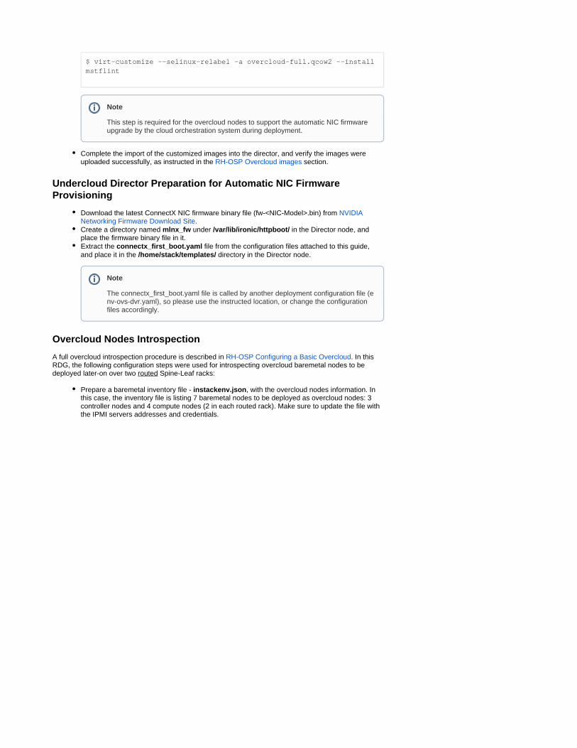
$ virt-customize --selinux-relabel -a overcloud-full.qcow2 --install mstflint
Complete the import of the customized images into the director, and verify the images were uploaded successfully, as instructed in the section.RH-OSP Overcloud images
Undercloud Director Preparation for Automatic NIC Firmware Provisioning
Download the latest ConnectX NIC firmware binary file (fw-<NIC-Model>.bin) from NVIDIA .Networking Firmware Download Site
Create a directory named under in the Director node, and mlnx_fw /var/lib/ironic/httpboot/place the firmware binary file in it.Extract the file from the configuration files attached to this guide, connectx_first_boot.yamland place it in the directory in the Director node./home/stack/templates/
Overcloud Nodes Introspection
A full overcloud introspection procedure is described in . In this RH-OSP Configuring a Basic OvercloudRDG, the following configuration steps were used for introspecting overcloud baremetal nodes to be deployed later-on over two Spine-Leaf racks:routed
Prepare a baremetal inventory file - , with the overcloud nodes information. In instackenv.jsonthis case, the inventory file is listing 7 baremetal nodes to be deployed as overcloud nodes: 3 controller nodes and 4 compute nodes (2 in each routed rack). Make sure to update the file with the IPMI servers addresses and credentials.
Note
This step is required for the overcloud nodes to support the automatic NIC firmware upgrade by the cloud orchestration system during deployment.
Note
The connectx_first_boot.yaml file is called by another deployment configuration file (e, so please use the instructed location, or change the configuration nv-ovs-dvr.yaml)
files accordingly.

instackenv.json
{ "nodes": [ { "name": "controller-1", "pm_type":"ipmi", "pm_user":"rcon", "pm_password":"********", "pm_addr":"172.15.1.1" }, { "name": "controller-2", "pm_type":"ipmi", "pm_user":"rcon", "pm_password":"********", "pm_addr":"172.15.1.2" }, { "name": "controller-3", "pm_type":"ipmi", "pm_user":"rcon", "pm_password":"********", "pm_addr":"172.15.1.3" }, { "name": "compute-1", "pm_type":"ipmi", "pm_user":"rcon", "pm_password":"********", "pm_addr":"172.15.1.11" }, { "name": "compute-2", "pm_type":"ipmi", "pm_user":"rcon", "pm_password":"********", "pm_addr":"172.15.1.12" }, { "name": "compute-3", "pm_type":"ipmi", "pm_user":"rcon", "pm_password":"********", "pm_addr":"172.15.1.13" }, { "name": "compute-4", "pm_type":"ipmi", "pm_user":"rcon", "pm_password":"********", "pm_addr":"172.15.1.14" } ]}
Import the overcloud baremetal nodes inventory, and wait until all nodes are listed in "manageable" state.
[stack@rhosp-director ~]$ source ~/stackrc(undercloud) [stack@rhosp-director ~]$ openstack overcloud node import /home/stack/instackenv.json

$ openstack baremetal node list+--------------------------------------+--------------+---------------+-------------+--------------------+-------------+| UUID | Name | Instance UUID | Power State | Provisioning State | Maintenance |+--------------------------------------+--------------+---------------+-------------+--------------------+-------------+| 476c7659-abc2-4d8c-9532-1756abbfd18a | controller-1 | None | power off | manageable | False || 3cbb74e5-6508-4ec8-91a8-870dbf28baed | controller-2 | None | power off | manageable | False || 457b329e-f1bc-476a-996d-eb82a56998e8 | controller-3 | None | power off | manageable | False || 870445b7-650f-40fc-8ac2-5c3df700ccdc | compute-1 | None | power off | manageable | False || baa7356b-11ca-4cb0-b58c-16c110bbbea0 | compute-2 | None | power off | manageable | False || e1bcfc51-7d63-4456-9105-a8a6955ee151 | compute-3 | None | power off | manageable | False || bc9bf23e-a8f5-46c0-8d2e-82b725f8fdde | compute-4 | None | power off | manageable | False |+--------------------------------------+--------------+---------------+-------------+--------------------+-------------+
Start the baremetal nodes introspection:
$ openstack overcloud node introspect --all-manageable
Set the root device for deployment, and provide all baremetal nodes to reach "available" state:
$ openstack overcloud node configure --all-manageable --instance-boot-option local --root-device largest$ openstack overcloud node provide --all-manageable
Tag the controller nodes into the "control" profile, which is later mapped to the overcloud controller role:
$ openstack baremetal node set --property capabilities='profile:control,boot_option:local' controller-1$ openstack baremetal node set --property capabilities='profile:control,boot_option:local' controller-2$ openstack baremetal node set --property capabilities='profile:control,boot_option:local' controller-3
Create a new compute flavor, and tag 2 compute nodes into the "compute-r0" profile, which is later mapped to the overcloud "compute in rack 0" role:
Note
The Role to Profile mapping is specified in the node-info.yaml file used during the overcloud deployment.

$ openstack flavor create --id auto --ram 4096 --disk 40 --vcpus 1 compute-r0$ openstack flavor set --property "capabilities:boot_option"="local" --property "capabilities:profile"="compute-r0" --property "resources:CUSTOM_BAREMETAL"="1" --property "resources:DISK_GB"="0" --property "resources:MEMORY_MB"="0" --property "resources:VCPU"="0" compute-r0
$ openstack baremetal node set --property capabilities='profile:compute-r0,boot_option:local' compute-1$ openstack baremetal node set --property capabilities='profile:compute-r0,boot_option:local' compute-2
Create a new compute flavor, and tag the last 2 compute nodes into the "compute-r1" profile, which is later mapped to the overcloud "compute in rack 1" role:
$ openstack flavor create --id auto --ram 4096 --disk 40 --vcpus 1 compute-r1$ openstack flavor set --property "capabilities:boot_option"="local" --property "capabilities:profile"="compute-r1" --property "resources:CUSTOM_BAREMETAL"="1" --property "resources:DISK_GB"="0" --property "resources:MEMORY_MB"="0" --property "resources:VCPU"="0" compute-r1
$ openstack baremetal node set --property capabilities='profile:compute-r1,boot_option:local' compute-3$ openstack baremetal node set --property capabilities='profile:compute-r1,boot_option:local' compute-4
Verify the overcloud nodes profiles allocation:
$ openstack overcloud profiles list+--------------------------------------+--------------+-----------------+-----------------+-------------------+| Node UUID | Node Name | Provision State | Current Profile | Possible Profiles |+--------------------------------------+--------------+-----------------+-----------------+-------------------+| 476c7659-abc2-4d8c-9532-1756abbfd18a | controller-1 | available | control | || 3cbb74e5-6508-4ec8-91a8-870dbf28baed | controller-2 | available | control | || 457b329e-f1bc-476a-996d-eb82a56998e8 | controller-3 | available | control | || 870445b7-650f-40fc-8ac2-5c3df700ccdc | compute-1 | available | compute-r0 | || baa7356b-11ca-4cb0-b58c-16c110bbbea0 | compute-2 | available | compute-r0 | || e1bcfc51-7d63-4456-9105-a8a6955ee151 | compute-3 | available | compute-r1 | || bc9bf23e-a8f5-46c0-8d2e-82b725f8fdde | compute-4 | available | compute-r1 | |+--------------------------------------+--------------+-----------------+-----------------+-------------------+
Overcloud Deployment Configuration Files
Prepare the following cloud deployment configuration files, and place it under the /home/stack/templates. /dvr directory

containers-prepare-parameter.yamlnetwork-environment-dvr.yamlcontroller-r0.yaml
computesriov-r0-dvr.yaml
computesriov-r1-dvr.yaml
node-info.yaml
roles_data_dvr.yaml
network_data.yaml
env-ovs-dvr.yaml
Overcloud Deployment
Issue the overcloud deploy command to start cloud deployment with the prepared configuration files.
Note
The full files are attached to this article, and can be downloaded here: RDG_OSP16.1_Config_Files.zip
Some configuration files are customized specifically the to the /home/stack/templates/dvr
location. If you place the template files in a different location, adjust it accordingly.
This template file contains the network settings for the controller nodes located in the network segment, including large MTU and bonding configurationRack0
This template file contains the network settings for compute nodes located in the Rac network segment, including SR-IOV VFs, large MTU and accelerated bonding (VF-k0
LAG) configuration for data path.
This template file contains the network settings for compute nodes located in the Rac network segment, including SR-IOV VFs, large MTU and accelerated bonding (VF-k1
LAG) configuration for data path.
This environment file contains the count of nodes per role and the role to the baremetal profile mapping.
This environment file contains the services enabled on each cloud role and the networks associated with its rack location.
This environment file contains a cloud network configuration for routed Spine-Leaf topology with large MTU. and segments are listed as subnets of Rack0 Rack1 L3each cloud network. For further information refer to RH-OSP Configuring the
.Overcloud Leaf Networks
This environment file contains the following settings:
Overcloud nodes time settingsConnectX First Boot parameters (by calling /home/stack/templates
file)/connectx_first_boot.yamlNeutron Jumbo Frame MTU and DVR modeNVIDIA T4 alias for GPU PCI passthroughCompute nodes CPU partitioning and isolation adjusted to Numa topologyNova PCI passthrough settings adjusted to VXLAN hardware offload

$ openstack overcloud deploy --templates /usr/share/openstack-tripleo-heat-templates \--libvirt-type kvm \-n /home/stack/templates/dvr/network_data.yaml \-r /home/stack/templates/dvr/roles_data_dvr.yaml \--validation-warnings-fatal \-e /home/stack/templates/dvr/node-info.yaml \-e /home/stack/templates/dvr/containers-prepare-parameter.yaml \-e /usr/share/openstack-tripleo-heat-templates/environments/podman.yaml \-e /usr/share/openstack-tripleo-heat-templates/environments/network-isolation.yaml \-e /usr/share/openstack-tripleo-heat-templates/environments/neutron-ovs-dvr.yaml \-e /home/stack/templates/dvr/network-environment-dvr.yaml \-e /home/stack/templates/dvr/env-ovs-dvr.yaml \-e /usr/share/openstack-tripleo-heat-templates/environments/disable-telemetry.yaml
Once deployed, load the necessary environment variables to interact with your overcloud:
$ source ~/overcloudrc
Applications and Use Cases
Accelerated Packet Processing (SDN Acceleration)
Logical Topology
VM Image
Build a VM cloud image (qcow2) with packet processing performance tools and cloud-init elements as described in How-to: Create OpenStack Cloud Image with Performance Tools.Upload the image to the overcloud image store:
$ openstack image create perf --public --disk-format qcow2 --container-format bare --file /home/stack/images/guest/centos8-perf.qcow2
VM Flavor
Create a flavor :
Note
The following use case is demonstrating SDN layer acceleration using hardware offload capabilities. The tests include a Telco grade benchmark that aims to push SDN offload into optimal performance and validate its functionality.

$ openstack flavor create m1.packet --id auto --ram 8192 --disk 20 --vcpus 10
Set hugepages and cpu-pinning parameters:
$ openstack flavor set m1.packet --property hw:mem_page_size=large$ openstack flavor set m1.packet --property hw:cpu_policy=dedicated
VM Networks and Ports
Create a VXLAN network with normal ports to be used for instance management and access:
$ openstack network create vx_mgmt --provider-network-type vxlan --share$ openstack subnet create vx_mgmt_subnet --dhcp --network vx_mgmt --subnet-range 22.22.22.0/24 --dns-nameserver 8.8.8.8$ openstack port create normal1 --network vx_mgmt --no-security-group --disable-port-security$ openstack port create normal2 --network vx_mgmt --no-security-group --disable-port-security
Create a VXLAN network to be used for accelerated data traffic between the VM instances with Jumbo Frames support:
$ openstack network create vx_data --provider-network-type vxlan --share --mtu 8950$ openstack subnet create vx_data_subnet --dhcp --network vx_data --subnet-range 33.33.33.0/24 --gateway none
Create 3 x SR-IOV direct ports with hardware offload capabilities:
$ openstack port create direct1 --vnic-type=direct --network vx_data --binding-profile '{"capabilities":["switchdev"]}'$ openstack port create direct2 --vnic-type=direct --network vx_data --binding-profile '{"capabilities":["switchdev"]}'$ openstack port create direct3 --vnic-type=direct --network vx_data --binding-profile '{"capabilities":["switchdev"]}'
Create an external network for public access:
$ openstack network create public --provider-physical-network datacentre --provider-network-type flat --external $ openstack subnet create public_subnet --no-dhcp --network public --subnet-range 10.7.208.0/24 --allocation-pool start=10.7.208.65,end=10.7.208.126 --gateway 10.7.208.1
Create a public router, and add the management network subnet:
$ openstack router create public_router$ openstack router set public_router --external-gateway public$ openstack router add subnet public_router vx_mgmt_subnet
VM Instance
TRex instance requires 2 ports to operate, even when a single port is used

Create a VM instance with a management port and 2 direct ports on a compute node located on the L3 network segment: Rack0
$ openstack server create --flavor m1.packet --image perf --port normal1 --port direct1 --port direct3 trex --availability-zone nova:overcloud-computesriov-rack0-0.localdomain
Create a VM instance with a management port and a single direct port on a compute node located on the L3 network segment: Rack1
$ openstack server create --flavor m1.packet --image perf --port normal2 --port direct2 testpmd --availability-zone nova:overcloud-computesriov-rack1-0.localdomain
Wait until the VM instances status is changed to ACTIVE:
$ openstack server list+--------------------------------------+---------+--------+---------------------------------------------------------+-------+--------+| ID | Name | Status | Networks | Image | Flavor |+--------------------------------------+---------+--------+---------------------------------------------------------+-------+--------+| 000d3e17-9583-4885-aa2d-79c3b5df3cc8 | testpmd | ACTIVE | vx_data=33.33.33.244; vx_mgmt=22.22.22.151 | perf | || 150013ad-170d-4587-850e-70af692aa74c | trex | ACTIVE | vx_data=33.33.33.186, 33.33.33.163; vx_mgmt=22.22.22.59 | perf | |+--------------------------------------+---------+--------+---------------------------------------------------------+-------+--------+
Verification
On the compute nodes that are hosting the VMs:
Confirm a DVR qrouter nameserver instance was created for external connectivity
[root@overcloud-computesriov-rack0-0 heat-admin]# ip netnsqrouter-a09dfa55-ad15-45a3-9a8a-d08e729bb512
Check compute node Numa topology and NIC Numa node association:
[root@overcloud-computesriov-rack0-0 heat-admin]# numactl -Havailable: 2 nodes (0-1)node 0 cpus: 0 1 2 3 4 5 12 13 14 15 16 17node 0 size: 64100 MBnode 0 free: 54629 MBnode 1 cpus: 6 7 8 9 10 11 18 19 20 21 22 23node 1 size: 64509 MBnode 1 free: 49202 MBnode distances:node 0 1 0: 10 21 1: 21 10
[root@overcloud-computesriov-rack0-0 heat-admin]# cat /sys/class/net/ens1f0/device/numa_node 0

Access the nova_compute container on the compute nodes that are hosting the VMs, and confirm optimal CPU pinning:
[root@overcloud-computesriov-rack0-0 heat-admin]# podman exec -it -u root nova_compute bash()[root@overcloud-computesriov-rack0-0 /]# virsh list Id Name State----------------------------------- 1 instance-00000002 running
()[root@overcloud-computesriov-rack0-0 /]# virsh vcpupin 1 VCPU CPU Affinity---------------------- 0 15 1 2 2 3 3 4 4 5 5 16 6 17 7 12 8 13 9 14
On one of the controller nodes:
Identify the network nameserver associated with the VXLAN management subnet:
[root@overcloud-controller-0 heat-admin]# ip netnsfip-95f6a318-c9ac-4dc4-a547-58c5b3da4798 (id: 3)qrouter-a09dfa55-ad15-45a3-9a8a-d08e729bb512 (id: 2)qdhcp-c7be692e-9404-40a5-8617-6ad8ac9941ed (id: 1)qdhcp-55d378ae-dfc7-4eb5-8b62-e23343677058 (id: 0)
[root@overcloud-controller-0 heat-admin]# ip netns exec qdhcp-55d378ae-dfc7-4eb5-8b62-e23343677058 ip addr show | grep -w inet inet 127.0.0.1/8 scope host lo inet 22.22.22.2/24 brd 22.22.22.255 scope global tap36d1260e-92
SSH from the controller node to the VMs via the VXLAN management subnet:
In our example, the ConnectX NIC is associated with Numa node 0, which is hosting CPU cores: 0 1 2 3 4 5 12 13 14 15 16 17.
Cores 2-5, 12-17 were isolated from the hypervisor and dedicated to Nova instance usage - See the cloud deployment files.
The VM instance vCPU cores were pinned to host cores from Numa 0, as expected.
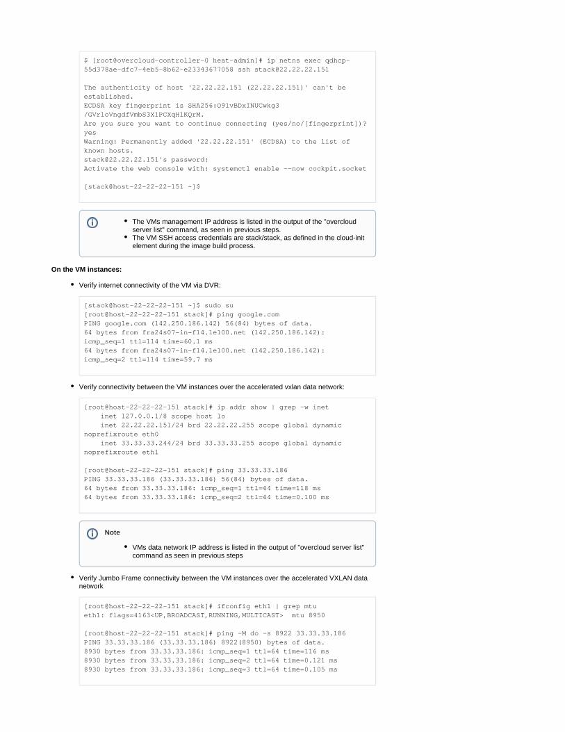
$ [root@overcloud-controller-0 heat-admin]# ip netns exec qdhcp-55d378ae-dfc7-4eb5-8b62-e23343677058 ssh [email protected]
The authenticity of host '22.22.22.151 (22.22.22.151)' can't be established.ECDSA key fingerprint is SHA256:O9lvBDxINUCwkg3/GVrloVngdfVmbS3X1PCXqHlKQrM.Are you sure you want to continue connecting (yes/no/[fingerprint])? yesWarning: Permanently added '22.22.22.151' (ECDSA) to the list of known [email protected]'s password: Activate the web console with: systemctl enable --now cockpit.socket
[stack@host-22-22-22-151 ~]$
On the VM instances:
Verify internet connectivity of the VM via DVR:
[stack@host-22-22-22-151 ~]$ sudo su[root@host-22-22-22-151 stack]# ping google.comPING google.com (142.250.186.142) 56(84) bytes of data.64 bytes from fra24s07-in-f14.1e100.net (142.250.186.142): icmp_seq=1 ttl=114 time=60.1 ms64 bytes from fra24s07-in-f14.1e100.net (142.250.186.142): icmp_seq=2 ttl=114 time=59.7 ms
Verify connectivity between the VM instances over the accelerated vxlan data network:
[root@host-22-22-22-151 stack]# ip addr show | grep -w inet inet 127.0.0.1/8 scope host lo inet 22.22.22.151/24 brd 22.22.22.255 scope global dynamic noprefixroute eth0 inet 33.33.33.244/24 brd 33.33.33.255 scope global dynamic noprefixroute eth1
[root@host-22-22-22-151 stack]# ping 33.33.33.186PING 33.33.33.186 (33.33.33.186) 56(84) bytes of data.64 bytes from 33.33.33.186: icmp_seq=1 ttl=64 time=118 ms64 bytes from 33.33.33.186: icmp_seq=2 ttl=64 time=0.100 ms
Verify Jumbo Frame connectivity between the VM instances over the accelerated VXLAN data network
[root@host-22-22-22-151 stack]# ifconfig eth1 | grep mtueth1: flags=4163<UP,BROADCAST,RUNNING,MULTICAST> mtu 8950
[root@host-22-22-22-151 stack]# ping -M do -s 8922 33.33.33.186PING 33.33.33.186 (33.33.33.186) 8922(8950) bytes of data.8930 bytes from 33.33.33.186: icmp_seq=1 ttl=64 time=116 ms8930 bytes from 33.33.33.186: icmp_seq=2 ttl=64 time=0.121 ms8930 bytes from 33.33.33.186: icmp_seq=3 ttl=64 time=0.105 ms
The VMs management IP address is listed in the output of the "overcloud server list" command, as seen in previous steps.The VM SSH access credentials are stack/stack, as defined in the cloud-init element during the image build process.
Note
VMs data network IP address is listed in the output of "overcloud server list" command as seen in previous steps

Performance Testing
iperf TCP Test
On the Transmitter VM, disable XPS (Transmit Packet Steering):
# for i in {0..7}; do echo 0 > /sys/class/net/eth1/queues/tx-$i/xps_cpus; done;
On the Receiver VM, start multiple iperf3 servers:
# iperf3 -s -p 5101&# iperf3 -s -p 5102&# iperf3 -s -p 5103&# iperf3 -s -p 5104&
On the Transmitter VM, start multiple iperf3 clients for multi-core parallel streams:
# iperf3 -c 33.33.33.244 -T s1 -p 5101 -t 120 &# iperf3 -c 33.33.33.244 -T s2 -p 5102 -t 120 &# iperf3 -c 33.33.33.244 -T s3 -p 5103 -t 120 &# iperf3 -c 33.33.33.244 -T s4 -p 5104 -t 120 &
Check the results:
Note
The tools used in the below tests are included in the VM image built with the perf-tools element, as instructed in previous steps.
This step is required to allow packet distribution of the iperf traffic using ConnectX VF-LAG.Use interface statistic/counters on the Leaf switches bond interfaces to confirm traffic is distributed by the Transmitter VM to both switches using VF-LAG (Cumulus "net show counters" command).

s3: - - - - - - - - - - - - - - - - - - - - - - - - -s3: [ ID] Interval Transfer Bitrate Retrs3: [ 5] 0.00-120.00 sec 346 GBytes 24.8 Gbits/sec 1677 senders3: [ 5] 0.00-120.04 sec 346 GBytes 24.8 Gbits/sec receivers3: s3: iperf Done.s2: [ 5] 119.00-120.00 sec 3.22 GBytes 27.6 Gbits/sec 0 3.22 MBytes s2: - - - - - - - - - - - - - - - - - - - - - - - - -s2: [ ID] Interval Transfer Bitrate Retrs2: [ 5] 0.00-120.00 sec 390 GBytes 27.9 Gbits/sec 1193 senders2: [ 5] 0.00-120.04 sec 390 GBytes 27.9 Gbits/sec receivers2: s2: iperf Done.s1: [ 5] 119.00-120.00 sec 2.71 GBytes 23.3 Gbits/sec 0 3.02 MBytes s1: - - - - - - - - - - - - - - - - - - - - - - - - -s1: [ ID] Interval Transfer Bitrate Retrs1: [ 5] 0.00-120.00 sec 276 GBytes 19.7 Gbits/sec 1022 senders1: [ 5] 0.00-120.04 sec 276 GBytes 19.7 Gbits/sec receivers1: s1: iperf Done.s4: [ 5] 119.00-120.00 sec 4.29 GBytes 36.8 Gbits/sec 0 3.19 MBytes s4: - - - - - - - - - - - - - - - - - - - - - - - - -s4: [ ID] Interval Transfer Bitrate Retrs4: [ 5] 0.00-120.00 sec 359 GBytes 25.7 Gbits/sec 1033 senders4: [ 5] 0.00-120.04 sec 359 GBytes 25.7 Gbits/sec receivers4: s4: iperf Done.
Before proceeding to the next test, stop all iperf servers on the Receiver VM:
# killall iperf3iperf3: interrupt - the server has terminatediperf3: interrupt - the server has terminatediperf3: interrupt - the server has terminatediperf3: interrupt - the server has terminated
RoCE Bandwidth Test
On the Receiver VM, start the ib_write_bw server:
# ib_write_bw -R -a --report_gbits
On the Transmitter VM, start the ib_write_bw client:
# ib_write_bw -R -a --report_gbits 33.33.33.244
Check the test results:
---------------------------------------------------------------------
The test results above demonstrate a total of around 100Gbps line rate for IP TCP traffic.

------------------ RDMA_Write BW Test Dual-port : OFF Device : mlx5_0 Number of qps : 1 Transport type : IB Connection type : RC Using SRQ : OFF PCIe relax order: ON ibv_wr* API : ON TX depth : 128 CQ Moderation : 100 Mtu : 4096[B] Link type : Ethernet GID index : 3 Max inline data : 0[B] rdma_cm QPs : ON Data ex. method : rdma_cm--------------------------------------------------------------------------------------- local address: LID 0000 QPN 0x07f3 PSN 0x6a025e GID: 00:00:00:00:00:00:00:00:00:00:255:255:33:33:33:186 remote address: LID 0000 QPN 0x06e8 PSN 0x7696bd GID: 00:00:00:00:00:00:00:00:00:00:255:255:33:33:33:244--------------------------------------------------------------------------------------- #bytes #iterations BW peak[Gb/sec] BW average[Gb/sec] MsgRate[Mpps] 2 5000 0.11 0.10 6.495542 4 5000 0.22 0.21 6.603626 8 5000 0.43 0.43 6.742424 16 5000 0.87 0.85 6.631824 32 5000 1.73 1.70 6.625489 64 5000 3.46 3.46 6.752682 128 5000 6.88 6.78 6.624954 256 5000 13.64 13.37 6.526054 512 5000 26.89 26.28 6.416973 1024 5000 51.14 50.36 6.146967 2048 5000 84.02 83.54 5.099077 4096 5000 95.90 95.78 2.922959 8192 5000 96.45 96.42 1.471245 16384 5000 96.64 96.61 0.737042 32768 5000 96.70 96.70 0.368864 65536 5000 96.74 96.74 0.184518 131072 5000 96.76 96.76 0.092274 262144 5000 96.77 96.77 0.046145 524288 5000 96.78 96.78 0.023074 1048576 5000 96.78 96.78 0.011537 2097152 5000 96.78 96.78 0.005769 4194304 5000 96.78 96.78 0.002884 8388608 5000 96.78 96.78 0.001442

---------------------------------------------------------------------------------------
RoCE Bandwidth Test over LAG
On the Receiver VM, start ib_write_bw server with 2 QPs in order to utilize the VF-LAG infrastructure:
# ib_write_bw -R --report_gbits --qp 2
On the Transmitter VM, start ib_write_bw client with 2 QPs and a duration of 60 seconds:
# ib_write_bw -R --report_gbits 33.33.33.244 --qp 2 -D 60
Use interface statistic/counters on the Leaf switches facing the Transmitter VM to confirm traffic is distributed over the VF-LAG towards both switches during the test:
# watch -n 1 -d net show counters
Kernel Interface tableIface MTU RX_OK RX_ERR RX_DRP RX_OVR TX_OK TX_ERR TX_DRP TX_OVR Flg------------- ----- ---------- -------- -------- -------- ---------- -------- -------- -------- -----bond1 9216 80545788 0 89 0 25903701 0 0 0 BMmRUbond2 9216 8966289 0 9 0 74391671 0 1 0 BMmRUbond3 9216 31188972 0 36 0 21469790 0 1 0 BMmRUbond4 9216 2322300138 0 24 0 1536565903 0 1 0 BMmRUbond5 9216 881342 0 63 0 791907 0 3 0 BMmRU
Check the test results:
---------------------------------------------------------------------------------------- #bytes #iterations BW peak[Gb/sec] BW average[Gb/sec] MsgRate[Mpps] 65536 6340506 0.00 110.81 0.211350---------------------------------------------------------------------------------------
RoCE Latency Test
On the Receiver VM, start the ib_write_lat server:
# ib_write_lat -R
On the Transmitter VM, start the ib_write_lat client:
# ib_write_lat -R 33.33.33.244
Check the test results:
The test results above demonstrate around 100Gbps line rate for RDMA over Converged Ethernet (RoCE) traffic.
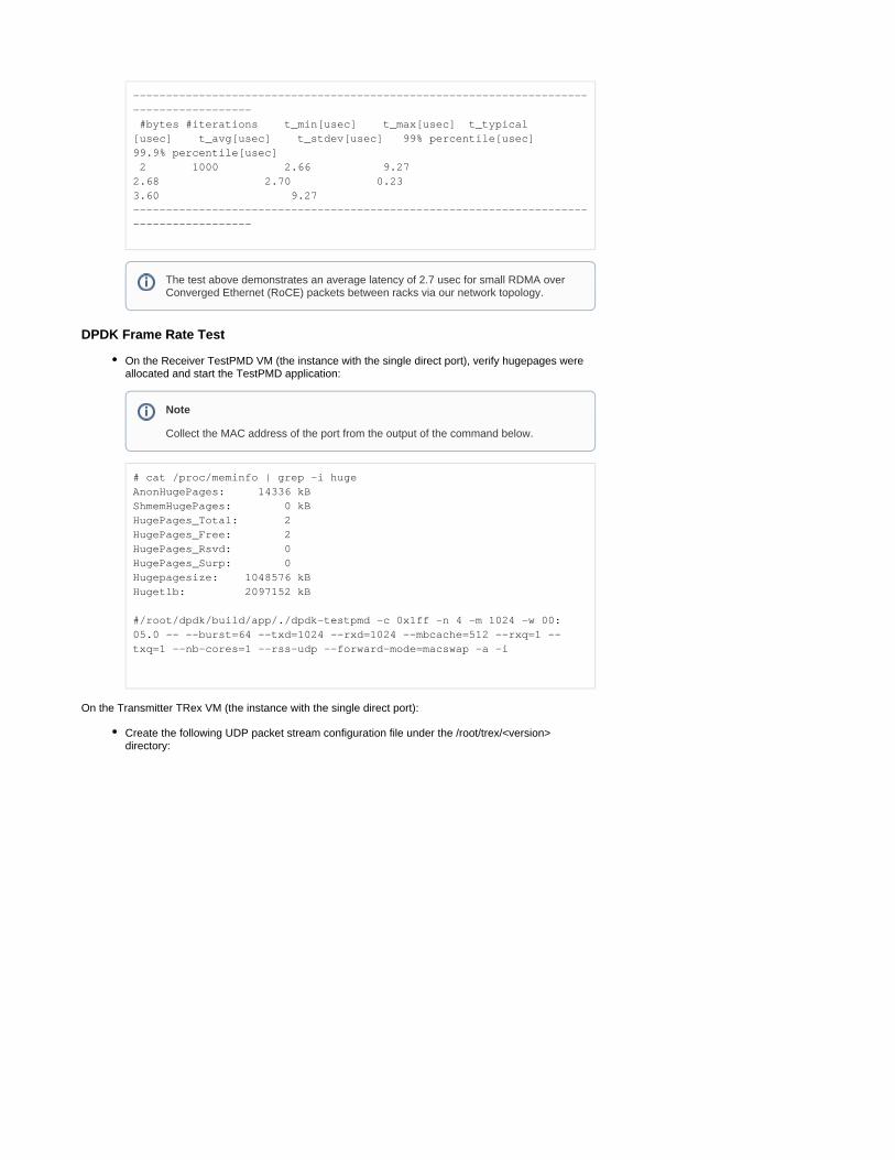
--------------------------------------------------------------------------------------- #bytes #iterations t_min[usec] t_max[usec] t_typical[usec] t_avg[usec] t_stdev[usec] 99% percentile[usec] 99.9% percentile[usec] 2 1000 2.66 9.27 2.68 2.70 0.23 3.60 9.27 ---------------------------------------------------------------------------------------
DPDK Frame Rate Test
On the Receiver TestPMD VM (the instance with the single direct port), verify hugepages were allocated and start the TestPMD application:
# cat /proc/meminfo | grep -i hugeAnonHugePages: 14336 kBShmemHugePages: 0 kBHugePages_Total: 2HugePages_Free: 2HugePages_Rsvd: 0HugePages_Surp: 0Hugepagesize: 1048576 kBHugetlb: 2097152 kB
#/root/dpdk/build/app/./dpdk-testpmd -c 0x1ff -n 4 -m 1024 -w 00:05.0 -- --burst=64 --txd=1024 --rxd=1024 --mbcache=512 --rxq=1 --txq=1 --nb-cores=1 --rss-udp --forward-mode=macswap -a -i
On the Transmitter TRex VM (the instance with the single direct port):
Create the following UDP packet stream configuration file under the /root/trex/<version> directory:
The test above demonstrates an average latency of 2.7 usec for small RDMA over Converged Ethernet (RoCE) packets between racks via our network topology.
Note
Collect the MAC address of the port from the output of the command below.

udp_rss.py
from trex_stl_lib.api import *
class STLS1(object):
def create_stream (self): pkt = Ether()/IP(src="16.0.0.1",dst="48.0.0.1")/UDP(dport=12)/(18*'x') vm = STLScVmRaw( [ STLVmFlowVar(name="v_port", min_value=4337, max_value=5337, size=2, op="inc"), STLVmWrFlowVar(fv_name="v_port", pkt_offset= "UDP.sport" ), STLVmFixChecksumHw(l3_offset="IP",l4_offset="UDP",l4_type=CTRexVmInsFixHwCs.L4_TYPE_UDP),
] )
return STLStream(packet = STLPktBuilder(pkt = pkt ,vm = vm ) , mode = STLTXCont(pps = 8000000) )
def get_streams (self, direction = 0, **kwargs): # create 1 stream return [ self.create_stream() ]
# dynamic load - used for trex console or simulatordef register(): return STLS1()
Run the DPDK port setup interactive wizard by following the steps specified below. When requested, use the MAC address of the TestPMD VM you collected in previous steps:

# cd /root/trex/v2.87# ./dpdk_setup_ports.py -iBy default, IP based configuration file will be created. Do you want to use MAC based config? (y/N)y+----+------+---------+-------------------+----------------------------------------------+------------+----------+----------+| ID | NUMA | PCI | MAC | Name | Driver | Linux IF | Active |+====+======+=========+===================+==============================================+============+==========+==========+| 0 | -1 | 00:03.0 | fa:16:3e:11:3e:64 | Virtio network device | virtio-pci | eth0 | *Active* |+----+------+---------+-------------------+----------------------------------------------+------------+----------+----------+| 1 | -1 | 00:05.0 | fa:16:3e:cb:a4:82 | ConnectX Family mlx5Gen Virtual Function | mlx5_core | eth1 | |+----+------+---------+-------------------+----------------------------------------------+------------+----------+----------+| 2 | -1 | 00:06.0 | fa:16:3e:58:79:e2 | ConnectX Family mlx5Gen Virtual Function | mlx5_core | eth2 | |+----+------+---------+-------------------+----------------------------------------------+------------+----------+----------+Please choose an even number of interfaces from the list above, either by ID, PCI or Linux IFStateful will use order of interfaces: Client1 Server1 Client2 Server2 etc. for flows.Stateless can be in any order.Enter list of interfaces separated by space (for example: 1 3) : 1 2
For interface 1, assuming loopback to its dual interface 2.Destination MAC is fa:16:3e:58:79:e2. Change it to MAC of DUT? (y/N).yPlease enter a new destination MAC of interface 1: FA:16:3E:32:5C:A4For interface 2, assuming loopback to its dual interface 1.Destination MAC is fa:16:3e:cb:a4:82. Change it to MAC of DUT? (y/N).yPlease enter a new destination MAC of interface 2: FA:16:3E:32:5C:A4Print preview of generated config? (Y/n)### Config file generated by dpdk_setup_ports.py ###
- version: 2 interfaces: ['00:05.0', '00:06.0'] port_info: - dest_mac: fa:16:3e:32:5c:a4 src_mac: fa:16:3e:cb:a4:82 - dest_mac: fa:16:3e:32:5c:a4 src_mac: fa:16:3e:58:79:e2
platform: master_thread_id: 0 latency_thread_id: 1 dual_if: - socket: 0 threads: [2,3,4,5,6,7,8,9]
Save the config to file? (Y/n)yDefault filename is /etc/trex_cfg.yamlPress ENTER to confirm or enter new file: Saved to /etc/trex_cfg.yaml.
Run the TRex application in the background over 8 out of 10 cores:

# nohup ./t-rex-64 --no-ofed-check -i -c 8 &
Run the TRex Console:
# ./trex-console
Using 'python3' as Python interpeter
Connecting to RPC server on localhost:4501 [SUCCESS]
Connecting to publisher server on localhost:4500 [SUCCESS]
Acquiring ports [0, 1]: [SUCCESS]
Server Info:
Server version: v2.87 @ STLServer mode: StatelessServer CPU: 8 x Intel Core Processor (Haswell, no TSX, IBRS)Ports count: 2 x 100Gbps @ ConnectX Family mlx5Gen Virtual Function
-=TRex Console v3.0=-
Type 'help' or '?' for supported actions
trex>
Run the TRex Console UI (TUI):
trex>tui
Start a 30MPPS stream using the stream configuration file created in previous steps:
tui>start -f udp_rss.py -m 30mpps -p 0
Check the test results:
Global Statistitcs
connection : localhost, Port 4501 total_tx_L2 : 15.34 Gbps version : STL @ v2.87 total_tx_L1 : 20.14 Gbps cpu_util. : 55.78% @ 8 cores (8 per dual port) total_rx : 14.13 Gbps rx_cpu_util. : 0.0% / 0 pps total_pps : 29.97 Mpps async_util. : 0.03% / 11.55 Kbps drop_rate : 0 bps total_cps. : 0 cps queue_full : 0 pkts

Accelerated Data Processing (GPU)
Logical Topology
VM Image
Build a VM cloud image (qcow2) with cUDA, MLNX_OFED and cloud-init elements, as described in How-to: Create OpenStack Cloud Image with NVIDIA GPU and Network Drivers.Upload the image to the overcloud image store:
$ openstack image create cuda --public --disk-format qcow2 --container-format bare --file /home/stack/images/guest/centos7-gpu.qcow2
VM Flavor
Create a flavor :
$ openstack flavor create m1.gpu --id auto --ram 8192 --disk 40 --vcpus 8
Set Tesla T4 GPU alias and ratio:
$ openstack flavor set m1.gpu --property "pci_passthrough:alias"="t4:1"
Increase the default cores quota :
$ openstack quota set --cores 40 admin
The test above demonstrates 30 MPPS frame rate for DPDK workload against a DPDK receiver with a single core, and should scale accordingly for multiple cores.
Note
The flavor configuration does not include cpu-pinning properties, due to the compute server board architecture used in this RDG (the NIC and GPU are not associated with the same Numa node). This limitation required us to disable the cpu_dedicated_set nova.conf setting on the relevant compute nodes, and restart the nova_compute service container before spawning the instances.
The "t4" alias used in the flavor is matching the Nova PCI alias set in the cloud configuration files of this RDG. For further information, please refer to RH-OSP
.Enabling PCI Passthrough for a GPU Device

VM Networks and Ports
Create 2 x normal ports to be used for instance management and access:
$ openstack port create normal3 --network vx_mgmt --no-security-group --disable-port-security$ openstack port create normal4 --network vx_mgmt --no-security-group --disable-port-security
Create 2 x SR-IOV direct ports with hardware offload capabilities:
$ openstack port create direct4 --vnic-type=direct --network vx_data --binding-profile '{"capabilities":["switchdev"]}'$ openstack port create direct5 --vnic-type=direct --network vx_data --binding-profile '{"capabilities":["switchdev"]}'
VM Instance
Create a VM instance with a management port and a direct port on the second compute node located on the L3 network segment: Rack0
$ openstack server create --flavor m1.gpu --image cuda --port normal3 --port direct4 gpu_vm1 --availability-zone nova:overcloud-computesriov-rack0-1.localdomain
Create a VM instance with a management port and a direct port on the second compute node located on the L3 network segment: Rack1
$ openstack server create --flavor m1.gpu --image cuda --port normal4 --port direct5 gpu_vm2 --availability-zone nova:overcloud-computesriov-rack1-1.localdomain
Wait until the VM instances status is changed to ACTIVE:
$ openstack server list | grep -i gpu| ea0fb2cf-04ae-4cfb-9f66-0892d8f27faa | gpu_vm2 | ACTIVE | vx_data=33.33.33.172; vx_mgmt=22.22.22.183 | cuda | || ce154553-6020-493e-ac48-60ae6f58cc0a | gpu_vm1 | ACTIVE | vx_data=33.33.33.58; vx_mgmt=22.22.22.13 | cuda | |
Verification
Use the method described in the packet processing use case to SSH into the VM instance via the controller node. On the VM, verify that the allocated NVIDIA GPU and VF are seen as PCI devices:
The same networks created in the previous use case can be used in this use case as well.

[root@gpu-vm1 stack]# lspci00:00.0 Host bridge: Intel Corporation 440FX - 82441FX PMC [Natoma] (rev 02)00:01.0 ISA bridge: Intel Corporation 82371SB PIIX3 ISA [Natoma/Triton II]00:01.1 IDE interface: Intel Corporation 82371SB PIIX3 IDE [Natoma/Triton II]00:01.2 USB controller: Intel Corporation 82371SB PIIX3 USB [Natoma/Triton II] (rev 01)00:01.3 Bridge: Intel Corporation 82371AB/EB/MB PIIX4 ACPI (rev 03)00:02.0 VGA compatible controller: Cirrus Logic GD 544600:03.0 Ethernet controller: Red Hat, Inc. Virtio network device00:04.0 SCSI storage controller: Red Hat, Inc. Virtio block device00:05.0 Ethernet controller: Mellanox Technologies ConnectX Family mlx5Gen Virtual Function00:06.0 3D controller: NVIDIA Corporation TU104GL [Tesla T4] (rev a1)00:07.0 Unclassified device [00ff]: Red Hat, Inc. Virtio memory balloon
Execute IP and RoCE connectivity and bandwidth tests between the GPU instances over the data network, as described in the packet processing use case example.
Authors
Itai Levy
Over the past few years, Itai Levy has worked as a Solutions Architect and member of the NVIDIA Networking “Solutions Labs” team. Itai designs and executes cutting-edge solutions around Cloud Computing, SDN, SDS and Security. His main areas of expertise include NVIDIA BlueField Data Processing Unit (DPU) solutions and accelerated OpenStack/K8s platforms.