r&d for the sponge cleaning of superconducting rf cavity · pdf filer&d for sponge...
TRANSCRIPT
R&D FOR SPONGE CLEANING OF SUPERCONDUCTING RF CAVITY
T. Saeki#, Y. Funahashi, H. Hayano, S. Kato, M. Nishiwaki, M. Sawabe, K. Ueno, K. Watanabe, KEK, Tsukuba, Ibaraki, Japan,
W. Clemens, R. L. Geng, R. Manus, JLAB, Newport News, Virginia, U.S.A.
Abstract The Electro-polishing (EP) process is the best candidate
of final surface treatment for the production of ILC cavities. Nevertheless, the broad distribution of the gradient caused by field emitters in cavities is still a serious problem for the EP process. Ethanol- and degreaser-rinse processes after the EP process were found to be effective to decrease the field emitters in recent studies, although these are not perfect yet. We tried to test the sponge cleaning as the post-EP process to remove the field emitters inside the cavity. This article describes the results of a test with a proto-type sponge-cleaning tool for single-cell cavity at KEK in collaboration with JLAB.
INTRODUCTION In the activities of Global Design Effort (GDE) to study
the construction of International Linear Collider (ILC), the acceptant gradient of produced SRF cavities was decided to be 35 MV/m in vertical test [1]. The yield rate of the cavity to be accepted beyond this threshold should be more than 90% to minimize the cost of ILC. Even if choosing one qualified company, the current yield rate of produced cavities is only 45%. In the standard recipe of cavity treatment, the Electro-Polishing (EP) is the final process to remove the inner surface of the cavity. However, the following rinsing processes; ultrasonic Ultra-Pure Water (UPW) rinse, Ethanol rinse, detergent rinse and High Pressure Rinse (HPR) seem not to be enough to remove residual particles on the inner surface of cavity after the EP process. This causes the field emission of cavities and also resultant broad distribution of gradient. In order to improve this situation, we started studying sponge cleaning as the post-EP process. The study was initiated by the fundamental experiment to test the effect of sponge-cleaning process with niobium (Nb) plate samples in collaboration with JLAB. The good results of this experiment were followed by the development of proto-type sponge-cleaning tool for single-cell cavity at KEK. This article describes the details of the studies and experiments of sponge-cleaning process and the development of sponge-cleaning tool.
SELECTION OF SPONGE MATERIAL The inner surface of cavity is rinsed by running UPW
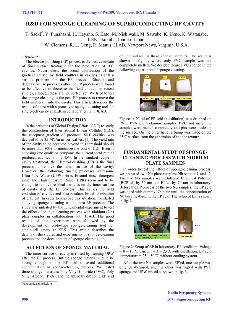
after the EP process. But the sponge material should be strong enough to the EP acid to avoid additional contamination in sponge-cleaning process. We tested three sponge materials; Poly Vinyl Chloride (PVC), Poly Vinyl Alcohol (PVA), and melamine by dropping EP acid
on the surface of these sponge samples. The result is shown in fig. 1, where only PVC sample was not completely melted. We decided to use PVC sponge in the following experiment of sponge cleaning.
Figure 1: 20 ml of EP acid (no dilution) was dropped on PVC, PVA and melamine samples. PVC and melamine samples were melted completely and pits were made on the surface. On the other hand, a bump was made on the PVC surface from the expansion of sponge texture.
FUNDAMENTAL STUDY OF SPONGE-CLEANING PROCESS WITH NIOBIUM
PLATE SAMPLES In order to test the effect of sponge-cleaning process,
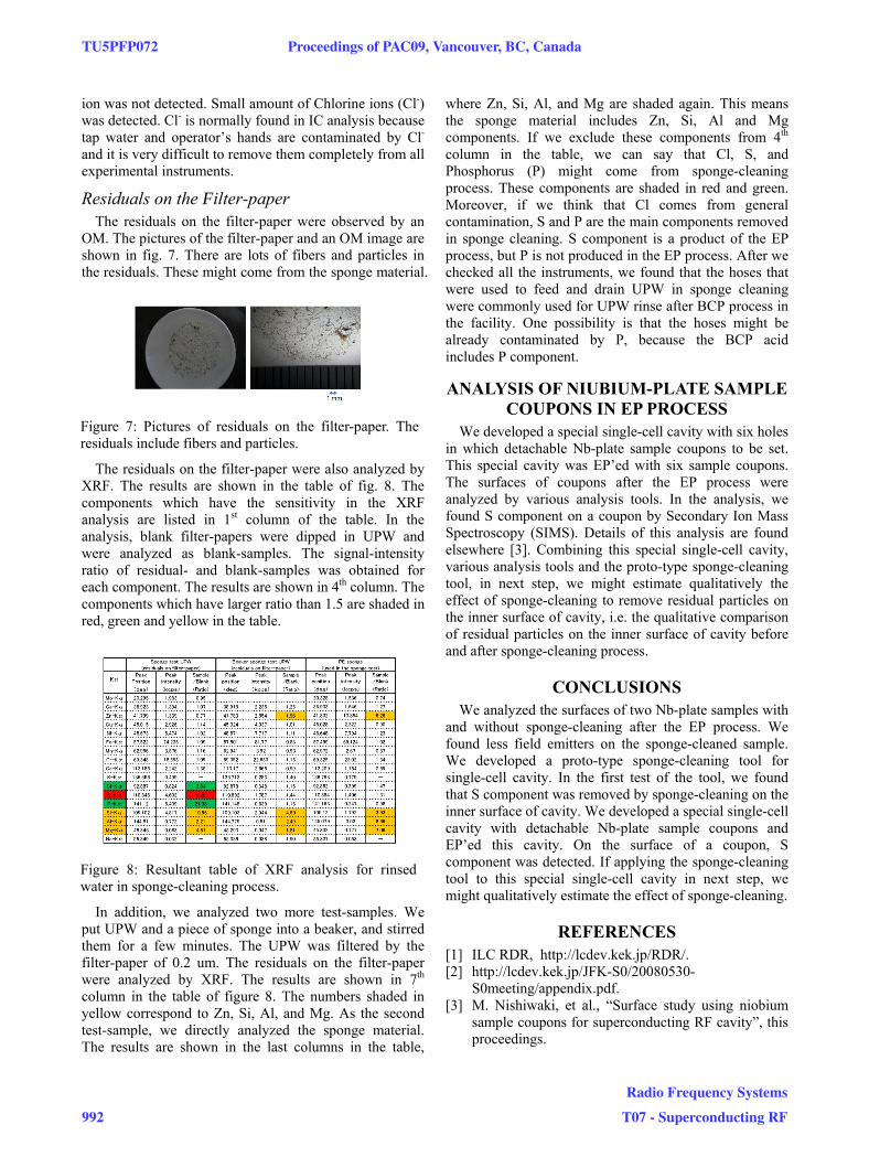
we prepared two Nb-plate samples; Nb-sample-1 and -2. The two Nb samples were Buffered Chemical Polished (BCP’ed) by 30 um and EP’ed by 70 um in laboratory. Before the EP process of the two Nb samples, the EP acid was aged with dummy Nb plate until the concentration of Nb became 4 g/L in the EP acid. The setup of EP is shown in fig. 2.
Figure 2: Setup of EP in laboratory. EP condition: Voltage = 8 ~ 13 V, Current = 3 ~ 23 A with oscillation, EP acid temperature = 25 ~ 50 0C without cooling system.
After the two Nb samples were EP’ed, one sample was only UPW-rinsed, and the other was wiped with PVC sponge and UPW-rinsed as shown in fig. 3.
___________________________________________
TU5PFP072 Proceedings of PAC09, Vancouver, BC, Canada
990
Radio Frequency Systems
T07 - Superconducting RF

Figure 3: Nb-sample-1 was processed through 1) UPW rinse, 3) packing, and 4) transportation. Nb-sample-2 was processed through 1) UPW rinse, 2) sponge-wipe + UPW rinse, 3) packing, and 4) transportation.
The two Nb samples with and without sponge-cleaning
were packed in transparent PVC containers filled with UPW, and transported to JLAB by air. The two Nb samples were analyzed by Scanning Field Emission Microscope (SFEM) at JLAB. The specification of SFEM is found elsewhere [2]. The results of analysis are shown in fig. 4.
Figure 4: Results of S EM analysis. Left-hand side: Nb-sample-1 w/o sponge-cleaning. Right-hand side: Nb-sample-2 w/ sponge-cleaning. Each horizontal line corresponds to a scan by SFEM. Each peak corresponds to a field emitter.
Many field emitters were found and lower Field Emission (FE) onset around 10 MV/m was observed on Nb-sample-1 without sponge-cleaning process. Much less field emitters and high FE onset were found in Nb-sample-2 with sponge-cleaning process.
DEVELOPMENT OF PROTO-TYPE SPONGE-CLEANING TOOL
Encouraged by the good results of fundamental study with Nb-plate samples, we developed a proto-type sponge-cleaning tool for single-cell cavity. The pictures and drawings of the tool are shown in fig. 5. Sponges are attached on the expandable structure around a rod. The rod is inserted into a cavity and the structure is expanded
for the sponges to be touched on the inner surface of cavity. The rod is rotated by a handle to wipe the inner surface of cavity. Before developing the tool, we tested Poly Ethylene (PE) sponge material with EP acid in addition to the three sponge materials already mentioned. The PE sponge kept the original surface and no corrosion was found even after dropping EP acid. Based on this test result, we used PE sponge material for the tool.
Figure 5: Left-hand side: drawings of proto-type sponge-cleaning tool for single-cell cavity. Right-hand side: pictures of sponge-cleaning tool.
The proto-type sponge-cleaning tool was tested by a
single-cell cavity. Before the test, the single-cell cavity was EP’ed and UPW-rinsed. The pictures of test are shown in fig. 6. The structure and rod of the tool was inserted into the cavity and UPW was fed into the cavity from the lower flange. The overflowed UPW from the upper flange was drained through a hose and kept in a container to be analyzed.
Figure 6: Test of proto-type sponge-cleaning tool.
The drained water was 10 L in volume and was analyzed by following sequence. 1) The water was filtered through the filter-paper of 0.2 um. 2) The filtered water was condensed to 70 mL in volume. 3) Ion Chromatography (IC) was applied to the condensed water. 4) The residuals on the filter-paper were observed by an Optical Microscope (OM), 5) and analyzed by X-ray Fluorescence analyzer (XRF).
Ion Chromatography (IC) Analysis 4.9 mg/L of Fluorine ions (F-) was detected in the
filtered and condensed water by IC analysis. Sulfur (S)
F
Proceedings of PAC09, Vancouver, BC, Canada TU5PFP072
Radio Frequency Systems
T07 - Superconducting RF 991
ion was not detected. Small amount of Chlorine ions (Cl-) was detected. Cl- is normally found in IC analysis because tap water and operator’s hands are contaminated by Cl- and it is very difficult to remove them completely from all experimental instruments.
Residuals on the Filter-paper The residuals on the filter-paper were observed by an
OM. The pictures of the filter-paper and an OM image are shown in fig. 7. There are lots of fibers and particles in the residuals. These might come from the sponge material.
Figure 7: Pictures of residuals on the filter-paper. The residuals include fibers and particles.
The residuals on the filter-paper were also analyzed by
XRF. The results are shown in the table of fig. 8. The components which have the sensitivity in the XRF analysis are listed in 1st column of the table. In the analysis, blank filter-papers were dipped in UPW and were analyzed as blank-samples. The signal-intensity ratio of residual- and blank-samples was obtained for each component. The results are shown in 4th column. The components which have larger ratio than 1.5 are shaded in red, green and yellow in the table.
Figure 8: Resultant table of XRF analysis for rinsed water in sponge-cleaning process.
In addition, we analyzed two more test-samples. We
put UPW and a piece of sponge into a beaker, and stirred them for a few minutes. The UPW was filtered by the filter-paper of 0.2 um. The residuals on the filter-paper were analyzed by XRF. The results are shown in 7th column in the table of figure 8. The numbers shaded in yellow correspond to Zn, Si, Al, and Mg. As the second test-sample, we directly analyzed the sponge material. The results are shown in the last columns in the table,
where Zn, Si, Al, and Mg are shaded again. This means the sponge material includes Zn, Si, Al and Mg components. If we exclude these components from 4th column in the table, we can say that Cl, S, and Phosphorus (P) might come from sponge-cleaning process. These components are shaded in red and green. Moreover, if we think that Cl comes from general contamination, S and P are the main components removed in sponge cleaning. S component is a product of the EP process, but P is not produced in the EP process. After we checked all the instruments, we found that the hoses that were used to feed and drain UPW in sponge cleaning were commonly used for UPW rinse after BCP process in the facility. One possibility is that the hoses might be already contaminated by P, because the BCP acid includes P component.
ANALYSIS OF NIUBIUM-PLATE SAMPLE COUPONS IN EP PROCESS
We developed a special single-cell cavity with six holes in which detachable Nb-plate sample coupons to be set. This special cavity was EP’ed with six sample coupons. The surfaces of coupons after the EP process were analyzed by various analysis tools. In the analysis, we found S component on a coupon by Secondary Ion Mass Spectroscopy (SIMS). Details of this analysis are found elsewhere [3]. Combining this special single-cell cavity, various analysis tools and the proto-type sponge-cleaning tool, in next step, we might estimate qualitatively the effect of sponge-cleaning to remove residual particles on the inner surface of cavity, i.e. the qualitative comparison of residual particles on the inner surface of cavity before and after sponge-cleaning process.
CONCLUSIONS We analyzed the surfaces of two Nb-plate samples with
and without sponge-cleaning after the EP process. We found less field emitters on the sponge-cleaned sample. We developed a proto-type sponge-cleaning tool for single-cell cavity. In the first test of the tool, we found that S component was removed by sponge-cleaning on the inner surface of cavity. We developed a special single-cell cavity with detachable Nb-plate sample coupons and EP’ed this cavity. On the surface of a coupon, S component was detected. If applying the sponge-cleaning tool to this special single-cell cavity in next step, we might qualitatively estimate the effect of sponge-cleaning.
REFERENCES [1] ILC RDR, http://lcdev.kek.jp/RDR/. [2] http://lcdev.kek.jp/JFK-S0/20080530-
S0meeting/appendix.pdf. [3] M. Nishiwaki, et al., “Surface study using niobium
sample coupons for superconducting RF cavity”, this proceedings.
TU5PFP072 Proceedings of PAC09, Vancouver, BC, Canada
992
Radio Frequency Systems
T07 - Superconducting RF