rd-ai56 489 national program for inspection of … · 17. distri1uution st atement (of the ahaltet...
TRANSCRIPT

RD-Ai56 489 NATIONAL PROGRAM FOR INSPECTION OF NON-FEDERAL DAMS 1/iTRICKLING FALLS DAM (..(U) CORPS OF ENGINEERS WALTHAMMA NEW ENGLAND DIV NOV 78
UNCLSSIFIED F/G 13/13 NL
,mmIImmhIIIIImhhmmmomhhhhl

2-1'
1111 *4* 1-
NATIONAL BUREAU C# STANDARDSMICROOPY RESOLUTION TEST CHART
.7i

c0 MERRIMACK RIVER BASIN
EAST KINGSTON, NEW HAMPSHIRE
L1nrum
I TRICKLING FALLS DAM
N H 00440
* NHWRB 72.01
PHASE I INSPECTION REPORT
NATIONAL DAM INSPECTION PROGRAM
DTICELECTEnhAEI~I JULI I98
DEPARTMENT OF THE ARMYNEW ENGLAND DIVISION, CORPS OF ENGINEERS
WALTHAM, MASS. 02154t()N srirE, rr.1' A . *-
Appfo-x(-d ict pubii. rsiaomN
NOVEMBER 1978 i Distzibution Unlimited
D1rid COPY .1 0 3 QQ.
w w w w w -, w w w 10
IINCt ASSTFTEDSECURITY CLASSIFICATION OF THIS PAGE (When Data hntewodJ
REPOT DOU)ANTATON PGEEAD INSTRUCTIONSREPOR DOCMENTAION AGE EFORE COMPLETING FORM1. REPORT NUMBER2.G M f CA'CTAL NBE
4. TITLE (and Subtitle) 6 TYPE OP REPORT &PERIOD COVERED
Tricklung Falls Dam ______________
NATIONAL PROGRAM FOR INSPECTION OF NON-FEDERAL * PERFORMING ONG. REPORT NUMBER
DAM& .____________
7. AUTHOR(@) a. COraACT on GRANT "uUew)
U.S. ARMY CORPS OF ENGINEERSNEW ENGLAND DIVISION
9. PERFORMING ORGANIZATION NAME AND ADDRESS 16. PROGRAM ELEMENT PROJECT, TASKCAREA 6 WORK UNIT NUMBERS
11. CONTROLLING OFFICE NAME AND ADDRESS 12. REPORT DATE
DEPT. OF THE ARMY, CORPS OF ENGINEERS 1% 4ember 1978NEW ENGLAND DIVISION, NEDED 13 NUMBER OF' PAGES
424 TRAPELO ROAD, WALTHAM, MA. 02254 4_________,____14.- MONITORING AGENCY NAME &ADORESS(If dift.'unt learn C~mlliaid 0111190) 1S. SECURITY CLASS. (of iled tuport)
UNCLASS I FIED1s. DECk ASSI PIC ATION/ DOWNGRADING
SON OULE
16. DISTRIBUTION STATEMENT (a# this Reoge)
APPROVAL FOR PUBLIC RELEASE: DISTRIBUTION UNLIMITED
17. DISTRI1UUTION ST ATEMENT (of the ahaltet enteed in block 1011i0,108s it W Aspol
I&. SUPPLEUWNTARY NOTESCover progtam reads: Phase I Inspection Report, National Dam Inspection Program;however, the official title of the program is: National Program for Inspection ofNon-Federal Dams; use cover date for date of report.
19. K EY WORDS (Contunue on revW60 side It 1006048MY MINd AdON1eii by block mumbe.)
* DAMS, INSPECTION, DAM SAFETY,
Merrimack River BasinEast Kingston, New HampshirePowwow River
* 20. ABSTRACT (Continue an reverse side it 0169616Man d IjuN11) bF block Inmus.)
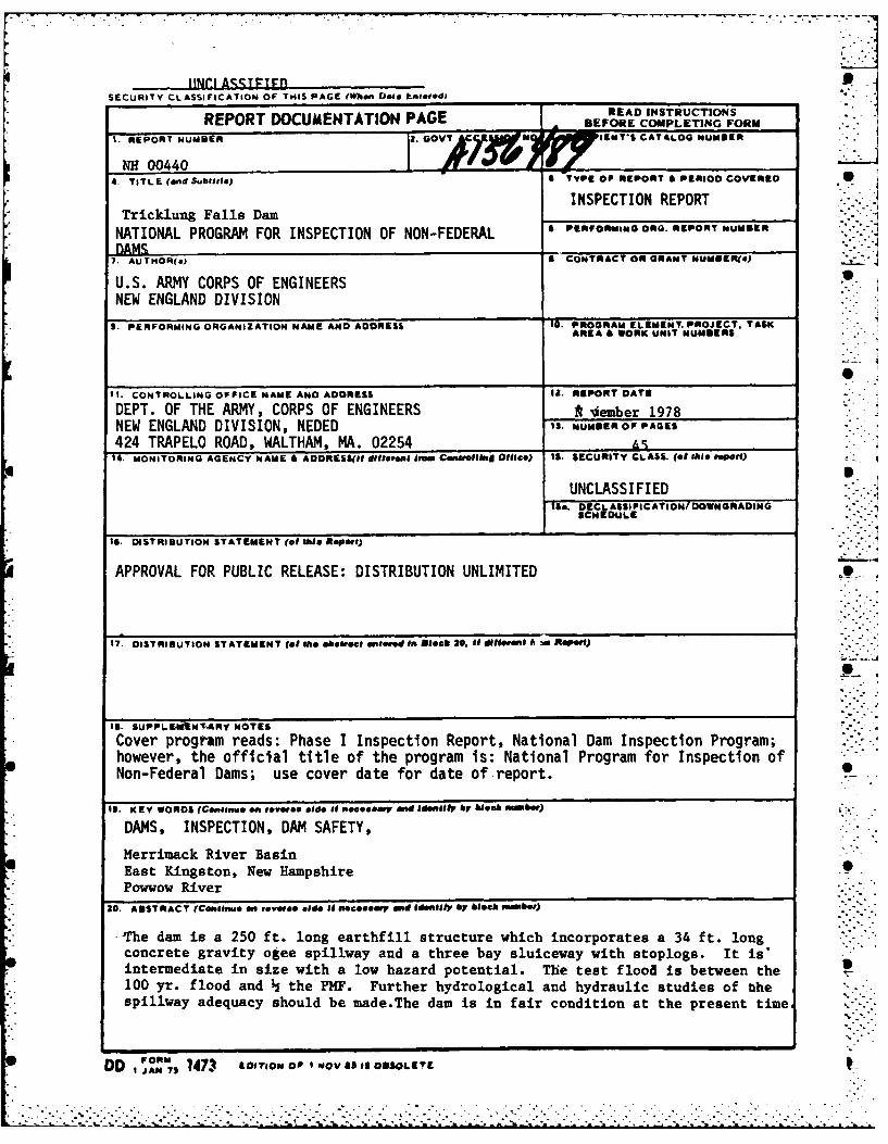
-The damn is a 250 ft. long earthf ill structure which incorporates a 34 ft. longconcrete gravity otee spillway and a three bay sluiceway with stoplogs. It is*intermediate in size with a low hazard potential. The test flood is between the100 yr. flood and h the PMF. Further hydrological and hydraulic studies of thespillway adequacy should be made.The dam is in fair condition at the present time
DO I IN7 1473 ILOITION OF NOV Of5IS OBSOLETE

*.-. .. . .
DISCLAIMER NOTICE
THIS DOCUMENT IS BEST QUALITYPRACTICABLE. THE COPY FURNISHEDTO DTIC CONTAINED A SIGNIFICANTNUMBER OF PAGES WHICH DO NOTREPRODUCE LEGIBLY.
°1

DEPARTMENT OF THE ARMY 0NEW ENGLAND DIVISION. CORPS OF ENGINEERS
~424 TRAPELO ROADREPLY TO WALTHAM, MASSACHUSETrS 02154
... " '" REPLY TO ' " " '-
ATTENTION OF:
NEDED
Honorable Hugh J. Gallen ..... -'-Governor of the State of New Hampshire S 0State HouseConcord, New Hampshire 03301
Dear Governor Gallen: 5. 0
I am forwarding to you a copy of the Trickling Falls Dam Phase IInspection Report, which was prepared under the National Program forInspection of Non-Federal Dams. This report is presented for your useand is based upon a visual inspection, a review of the past performanceand a brief hydrological study of the dam. A brief assessment is in- 5 6cluded at the beginning of the report. I have approved the report andsupport the findings and recommendations described in Section 7 and ask -.
that you keep me informed of the actions taken to implement them. Thisfollow-up action is a vitally important part of this program.
A copy of this report has been forwarded to the Water Resources Board, 0
the cooperating agency for the State of New Hampshire. In addition, a - ."copy of the report has also been furnished the owner, New HampshireWater Resources Board, 37 Pleasant Street, Concord, New Hampshire03301, ATTN: Mr. George M. McGee, Sr., Chairman.
Copies of this report will be made available to the public, uponrequest, by this office under the Freedom of Information Act. In thecase of this report the release date will be thirty days from the date. .
of this letter.
I wish to take this opportunity to thank you and the Water ResourcesBoard for your cooperation in carrying out this program.
Sincerely yours,
Incl P. CHANDLERAs stated C lonel, Corps of Engineers
"--l vision Engineer
S. .. . . II.-.. . . ... . . . . .. . . . . .. -.-- '.- -. . . . . . . . . . . . . . . . . . . . . . . . . . . . . .

- ~~~~~TRICKLING FALLS DAM _________
NH 00440 Aocesio ForNTIS GRA&I
DTIC TABoUllanynowncedJustitloati
Distributimig
Avaliblj1ti C eha0
F Stecial
MERRIMACK RIVER BASIN
K ~EAST KINGSTON, NEW HAMPSHIRE -.
PHASE I INSPECTION REPORTNATIONAL DAM INSPECTION PROGRAM
I 7 S

I---< ] - ] -
NATIONAL DAM INSPECTION PROGRAM
E. PHASE I REPORT '
Identification No.: NH 00440NHWRB No.: 72.01
* Name of Dam: TRICKLING FALLS DAMTown: East KingstonCounty and State: Rockingham County, New Hampshire SStream: Powwow RiverDate of Inspection: September 21, 1978
BRIEF ASSESSMENT
, The Trickling Falls Dam is a 250 foot long earthfill structure", which incorporates a 34 foot long, concrete gravity ogee spill-
r way and a three bay sluiceway with stoplogs. The dam, whichis owned by the New Hampshire Water Resources Board (NHWRB), 0has a maximum height of approximately 12 feet. While an earth-fill dam of some type has existed at the site since before 1940,major alterations in 1940 and 1962, both carried out by theNHWRB, have resulted in the structure's present configuration.
*. The dam, which lies on the Powwow River, is used primarily to 0control the level of Powwow Pond for recreational purposes.Some flood control functions are also served, however. The
.. 30.6 square mile drainage area consists of flat to steeplysloping forest. The dam's maximum impoundment of approximately
so 1700 acre-feet places it in the INTERMEDIATE size category,while the lack of any significant downstream hazard results in ,Oa LOW hazard potential classification.
Based on the size and hazard potential classification and inaccordance with the Corps' guidelines, the Test Flood (TF) isbetween the 100 year flood and one half the Probable MaximumFlood (PMF). The selected TF inflow of 7500 cfs results in apeak discharge at the dam of 6300 cfs. Since the maximumcapacity of the dam prior to overtopping is only approximately .-.. .2200 cfs, the TF would overtop the dam by more than 2 feet. -
*" For this reason, further hydrologic studies of the spillwayadequacy should be made.
°S
,. . .-

* - -. r-- .--°. .
* The dam is in FAIR condition at the present time and requiresconsiderable routine maintenance. Recommended remedial mea-sures include repair of erosion on the embankment, removal of pall trees and brush from the embankment, monitoring of two *...
small seepages, repair of deteriorated concrete surfaces andjoints, repair of a concrete wall, repair of safety railing,
-. clearing or trimming of trees and other potential obstructionsin and around the approach and downstream channels, and train-ing of local officials in dam operation to decrease responsetime in an emergency.
The improvements and recommendation outlined above should beimplemented within two years of receipt of the Phase I Inspec- -
-- tion Report by the owner. In light of the dam's FAIR condition,periodic technical inspections should be scheduled every two
.* years.
WVILLIAS. z[ RMRT\
n ~MINLJTOUi~~~o .2o9165.. ..N..o..32266.
%OALhg g
William S. Ziob er"-t-'..".New Hampshi egistration 3226 Massachusetts Registration 29165
L •
- I. . . . . . . . . . . . . . . . . . . . . .

I0 C0
This Phase I Inspection Report on Trickling Falls Damnhas been-reviewed by the undersigned Review Board members. In our
opinion, the reported findings, conclusions, and recommendations are
consistent with the Recommended Guidelines for Safety Inspection of ______
Dams, and with good engineering judgment and practice, and is hereby 0submitted for approval.
*
RICHARD F. DOH1ERTY, MEBER 0 0
Water Control BranchEngineering Division
* 0
CARNEY M. TERZI4N, MEMBERDesign Branch
ierng Division * 0
JOSEPH A. MCELROY, CHAIRM{AN
Chief, NED Materials Testing Lab.Foundations & Materials BranchEngineering Division
* 0
AP I VAT, .XE
0
JEB. FRYAR/Chief, Engineering Division
W~~ W o

PREFACE
This report is prepared under guidance contained in theRecommended Guidelines for Safety Inspection of Dams forPhase I Investigations. Copies of these guidelines may be
". obtained from the Office of Chief of Engineers, Washington,S D.C. 20314. The purpose of a Phase I Investigation is to
identify expeditiously those dams which may pose hazards to_ human life or property. The assessment of the general con-
dition of the dam is based upon available data and visualinspections. Detailed investigation and analyses involvingtopographic mapping, subsurface investigations, testing, and " 'detailed computational evaluations are beyond the scope ofa Phase I investigation; however, the investigation is inten-ded to identify any need for such studies.
In reviewing this report, it should be realized that thereported condition of the dam is based on observations offield conditions at the time of inspection along with dataavailable to the inspection team. In cases where the reser-voir was lowered or drained prior to inspection, such action,while improving the stability and safety of the dam, removesthe normal load on the structure and may obscure certain
- "conditions which might otherwise be detectable if inspectedunder the normal operating environment of the structure.
It is important to note that the condition of a dam dependson numerous and constantly changing internal and externalconditions, and is evolutionary in nature. It would beincorrect to assume that the present condition of the damwill continue to represent the condition of the dam at somepoint in the future. Only through continued care and inspec-
• tion can unsafe conditions be detected. "-. .'
Phase I inspections are not intended to provide detailedhydrologic and hydraulic analyses. In accordance with theestablished Guidelines, the Test Flood is based on theestimated "Probable Maximum Flood" for the region (greatestreasonably possible storm runoff), or fractions thereof. Be-cause of the magnitude and rarity of such a storm event, afinding that a spillway will not pass the Test Flood shouldnot be interpreted as necessarily posing a highly inadequatecondition. The Test Flood provides a measure of relativespillway capacity and serves as an aid in determining theneed for more detailed hydrologic and hydraulic studies,considering the size of the dam, its general condition and -the downstream damage potential.
~ K iv "''
S S.S S S -S S
...................................................

'I7
TABLE OF CONTENTS
Page
LETTER OF TRANSMITTAL
BRIEF ASSESSMENT
REVIEW BOARD SIGNATURE SHEET *
PREFACE iv
TABLE OF CONTENTS v
OVERVIEW PHOTOS vii
LOCATION MAP ix
SECTION 1 - PROJECT INFORMATION
1.1 General 1-11.2 Description of Project 1-2
- 1.3 Pertinent Data 1-4
SECTION 2 - ENGINEERING DATA
2.1 Design Records 2-12.2 Construction Records 2-12.3 Operational Records 2-i
- 2.4 Evaluation of Data 2-1
SECTION 3 - VISUAL INSPECTION•S
3.1 Findings 3-13.2 Evaluation 3-5
SECTION 4 - OPERATIONAL PROCEDURES
4.1 Procedures 4-14.2 Maintenance of Dam 4-14.3 Maintenance of Operating
Facilities 4-14.4 Description of Any Warning
System in Effect 4-14.5 Evaluation 4-1
v
.) -..?..-
- w.0 " "0°

Table of Contents - cont.
Page is
SECTION 5 -HYDRAULIC/HYDROLOGIC
5.1 Evaluation of Feature 5-15.2 Hydraulic/Hydrologic Evaluation 5-3
-_ 5.3 Downstream Dam Failure Hazard 0Estimate 5-4
SECTION 6 - STRUCTURAL STABILITY
6.1 Evaluation of StructuralStability 6-1 I
SECTION 7 - ASSESSMENT, RECOMMENDATIONS ANDREMEDIAL MEASURES
7.1 Dam Assessment 7-17.2 Recommendations 7-17.3 Remedial Measures 7-1
APPENDICES
[ APPENDIX A -VISUAL INSPECTION CHECKLIST A-i
APPENDIX B - FIGURES AND PERTINENT RECORDS B-I
APPENDIX C -PHOTOGRAPHS C-i
* • APPENDIX D -HYDROLOGIC AND HYDRAULIC SCOMPUTATIONS D-1
APPENDIX E - INFORMATION AS CONTAINED INTHE NATIONAL INVENTORY OF DAMS E-I
vi
.- • - .." .o . .
.-. . ".'i....ii... .i..-........ ...... i'o- - ) ~° - 2. .--. ".i-?.."I

Overview of damn from left sidedownstream (Sept. 21, 1978)
overview of dam from right sidedownstream (May 25, 1978)
vii

'da~
Overview of dam from left side upstream(Sept. 21, 1978)
viii

~~I r
* ~ .~r&~.,a 4 J
* ~ _X
m
;Ar m -..4 Bao
r~P".
SITE~
A ".
-O -vo'r
~~. I-
00
I. 2mil-
GODEG*.NW ILF &A")4N .AMYEGNERDVNW NLN
GET C ICAL- CO SLATSC4. f N IE RFRO M US S HA ERH LL, A EVIT N U PER ALL , MA S. ALTH M. ASS
FRO: UGS AVTRICKLI NW NG FPEALLS DMEWHAPSIR
SLE AS NOTEDDATE SEP 19T
.7 -

PHASE I INSPECTION REPORT
TRICKLING FALLS DAM
SECTION 1
PROJECT INFORMATION
1.1 General
(a) Authority
Public Law 92-367, August 8, 1972, authorized theSecretary of the Army, through the Corps of Engineers,to initiate a national program of dam inspection through- -
out the United States. The New England Division of the SCorps of Engineers has been assigned the responsibilityof supervising the inspection of dams within the NewEngland Region. Goldberg, Zoino, Dunnicliff & Associates,Inc. (GZD) has been retained by the New England Divisionto inspect and report on selected dams in the State ofNew Hampshire. Authorization and notice to proceed was Oissued to GZD under a letter of August 22, 1978 fromColonel Ralph T. Garver, Corps of Engineers. ContractNo. DACW 33-78-C-0303 has been assigned by the Corpsof Engineers for this work.
(b) Purpose
(1) Perform technical inspection and evaluationo' non-federal dams to identify conditions whichthreaten the public safety and thus permit cor-rection in a timely manner by non-federal inter-
" • ests. .
(2) Encourage and prepare the states to initiatequickly effective dam safety programs for non-federal dams.
(3) Update, verify and complete the National SInventory of Dams.
(c) Scope
The program provides for the inspection of non-federal dams in the high hazard potential category based Supon location of the dams and those dams in the signifi-cant hazard potential category believed to represent animmediate danger based on condition of the dam. .-
1-1-
* i . 6<.. . --..U •. % . . • . .U ... U - .. ' U . . . .. .. -. ,S .. ' .. .. S S .-

1.2 Description of Project
(a) Location
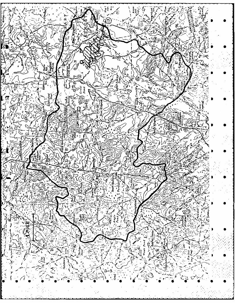
The Trickling Falls Dam lies on the Powwow Rivernear the intersection of Route 107A and the road connect-ing Route 107A with Route 108. This junction is approxi- . -mately 2.8 miles southeast of the town of Kingston. Theportion of the USGS Haverhill quadrangle presented onpage ix shows this locus. Figure 1 of Appendix B shows 0a site plan developed from the map and the visual inspec-tion.
-(b) Description of Dam and Appurtenances
This dam is a 250 foot long earthfill structurewhich incorporates a 34 foot wide concrete ogee spillwayand a three bay sluiceway equipped with stoplogs (PagesB-3 through B-5). Two of the sluiceway bays are 5 feetwide while the third is 5.5 feet wide. The inverts ofthe two leftmost sluiceways are 2 feet below the spill- *way crest while the invert of the third is 7.6 feet belowthe crest. A concrete walkway spans over the sluiceways.
- . The maximum height of the embankments and the concrete por-tions of the dam is approximately 12.0 feet. A brassplug at El. 114 (MSL) on the upstream face of the sluice- - -
K way structure serves as a reference point for water level- readings.
Ancillary portions of the outlet structure consistof two endwalls, the left one having a 900 wingwall up-stream of the sluiceway bays and a 900 return located at
" mthe downstream end of the structure. Construction draw-ings dated January 1940 indicate that a cut-off wall,located approximately 8 feet upstream of the stoplogslots, penetrates approximately 1 foot below grade 8 feet
"* into the left embankment. The right endwall, which is* approximately 45 feet long and which is normal to the
spillway axis, also contains a monolithically cast cut-off wall located normal to the endwall and in line withthe spillway axis.
S(c) Size Classification
The dam's maximum impoundment of 1700 acre-feet
falls within the 1000 to 50,000 acre-feet range whichdefines the INTERMEDIATE size category as defined in the"Recommended Guidelines." .:
1-2L o 0
S S.S S• 0.0 0, 0•0 0 0,0 0
...........................................
* S
(d) Hazard Potential Classification
With the possible exception of one house, there is . -.no significant development within the area which would .be affected by a failure of the dam. The only probableeffect on this house would be basement flooding since thefirst flocr is above the 6.4 feet flooding depth. Forthis reason, a hazard potential classification of LOWis assigned.
* 0(e) Ownership
The NHWRB owns this dam. Key officials are Chair-man George McGee, Chief Engineer Vernon Knowlton,
- Assistant Chief Engineer Donald Rapoza and Staff Engi-neers Pattu Kesavan and Gary Kerr. The Board's telephone * Snumber is (603) 271-3406 and it can also be reached throughthe State Capital operator at (603) 271-1110. The Merri-Mack Valley Power and Building Company turned the damover to the state in 1940.
(f) Operator
The NHWRB has permanent dam tenders who simultane-ously cover all dams owned by the state. The operatorscan be reached through the Board's engineers, who directall dam operations.
(g) Purpose of Dam
The primary purpose of the dam is to maintain the
" i~level of Powwow Pond for recreational use. The dam also . -provides some flood control benefits.
- L 0
(h) Design and Construction History
The Merrimack Valley Power and Building Company hadsome type of earthfill dam at the site prior to 1940(Pages B-6 and B-7). With the advent of state ownershipin 1940, the dam was significantly modified by the Sconstruction of a concrete spillway and sluiceway designedby Roland S. Burlingame of the NHWRB and by the enlarge-ment of the embankment (Page B-7). Additional modifica-tions, also designed by the NHWRB, occurred in 1962 whenthe original spillway was converted into two sluicewayswith stoplogs and a new concrete ogee spillway was added.These alterations resulted in the dam's present configura-tion.
1-3
.. ~~I 5i .".-p
. . . . . . ....... ..... .... ..... . .
..............
. .... .-... . .. . .-

(i) Normal Operational Procedure
A NHWRB dam tender visits the dam at least weeklyand reports water levels referenced to the brass plugback to the Concord office. The Board's engineers, inturn, direct any operations necessitated by the operator's
S.. input. In late summer or early fall, the pond is drawndown approximately one foot in anticipation of fallstorms and spring runoff.
1.3 Pertinent Data
(a) Drainage
The drainage area for Powwow Pond contains 30.6square miles of forested terrain varying from relativelyflat near the pond itself to steeply sloping in some
* portions farther west. The basin contains considerablepermanent development dispersed throughout the area.
(b) Discharge at Damsite
(1) Outlet Works
The dam's outlet works consist of the threebay sluiceway on the left side. Two of the baysare 5 feet wide while the third is 5.5 feet wide.The two leftmost bays have inverts at El. 111.8,while the right bay has its invert at El. 106.2.The sluiceways are intended to hold stoplogs upto the permanent crest elevation at El. 113.7.
(2) Maximum Known Flood at Dam Site 7
The maximum water level at the dam since the1962 reconstruction occurred in 1973 when waterflowed approximately 2.2 feet deep over the spill-way according to NHWRB records.
(3) Spillway capacity at maximum pool elevation:975 cfs at El. 118.2
(4) Gate capacity at normal pool elevation:450 cfs at El. 113.7
(5) Gate capacity at maximum pool elevation:1280 cfs at El. 118.2
1-4 ,. -' '-'='D 0
V V V V V V-V.V 6 V. U U-US_

(6) Total discharge capacity at maximum poolelevation: 2255 .fs at El. 118.2
*(c) Elevation (feet above MSL) j
(1) Top of dam: 118.2
- (2) Maximum pool: 118.2
(3) Recreational pool: 113.7 0
(4) Spillway crest: 113.7
(5) Streambed at centerline of dam: 106.2m
(6) Maximum tailwater: Unknown 5
(d) Reservoir
(1) Length of recreational pool: 1.1 miles
F (2) Length of maximum pool: Unknown S
* (e) Storage (acre-feet)
(1) Recreational pool: 400
1 (2) Top of Dam: 1700 0
(f) Reservoir Surface (acres)
• (1) Top dam: Unknown
- (2) Recreational pool: 288
(g) Dam
(1) Type: Earthfill
- (2) Length: 250 feet + 0
- (3) Height: 12 feet (structural and hydraulic)
(4) Top width: 15 feet +
(5) Side slopes: 2:1 0
(6) Zoning, impervious core and grout
curtain: Unknown .:..:
1-5 0
•. . . .. . . . .

(7) Cutoff: Plans indicate 1 foot thick concretewalls carried to impervious materialat back of spillway and at toe of
C. downstream apron and concrete corewalls extending from endwalls approxi-mately 8 feet into embankments and .-
within 1 foot of top of dam
S(f) Spillway
(1) Type: Concrete gravity
(2) Length of weir: 34 feet
(3) Crest elevation: 113.7 feet
(4) Gates: None
(5) U/S channel: Broad, deep approach from pond
(6) D/S channel: Wide with rock bottom andoverhanging vegetation 1 0
(g) Regulating Outlets
The size and inverts of the three bay sluiceway
are given in subparagraph 1.3(b) (1). Stoplogs are
manually installed and removed.
m 1-
* S
. . *. ... o . °

SECTION 2 - ENGINEERING DATA
2.1 Engineering Records S
The design of this dam is quite simple and incorporatesno unusual features. No original design drawings or calcula-tions are available. Significantly lacking are data concerningfoundation conditions and embankment construction.
2.2 Construction Records
Plans for the dam reconstructions in 1940 and 1962 areincluded in Appendix B. These drawings are, in general, quitedetailed and contain only minor deviations from the as-builtconfiguration.
2.3 Operation Records
The NHWRB operates the dam in a manner consistent withits intended purpose and engineering features.
2.4 Evaluation of Data
(a) Availability
The absence of design drawings and calculations andof foundation and embankment data are significant short- S Scomings, but are somewhat mitigated by the availabilityof the construction plans. An overall marginal assess-ment for availability is, therefore, warranted.
(b) Adequacy
The lack of in-depth engineering data does notpermit a definitive review. Therefore, the adequacy ofthe dam cannot be assessed from the standpoint of review-ing design and construction data. This assessment is thusbased primarily on the visual inspection, past performanceand sound engineering judgement. S S
(c) Validity
Since the observations of the inspection teamgenerally confirm the information contained in the con-struction drawings, a satisfactory evaluation for validity S S
is warrunted.
2-1
-. *.*: ~ - - - ~ -:°.-•. .- *.° :.::-: -... .: -:.,-. ..
2 . - . . . . . . . . . . . . . . . . . . . . . .
SECTION 3 - VISUAL OBSERVATIONS
3.1 Findings * S
(a) General
The Trickling Falls Dam is in FAIR condition at thepresent time. Considerable routine maintenance isrequired to correct minor deficiencies on all parts of 5the structure.
(b) Dam
- (1) Embankments (Photo 1)
The dam's embankment is divided into twosections, each approximately 100 feet long, by thespillway and the three bay sluiceway. Both sectionshave a maximum height of approximately 12 feet.Pages B-6 and B-7 contain the only informationavailable concerning the internal construction of I 0the embankments. As the plans indicate, the presentembankment was constructed by placing granularfill over an existing earthfill structure. Addi-tionally, the plans show concrete core walls extend-ing from the endwalls 8 feet into the embankments.
Inspection of the embankments revealed noevidence of horizontal or vertical movement. Someminor erosion is evident at the junction of theright endwall with the embankment, as riprap hasbeen placed on the upstream face and as the embank-I ~ ment is approximately 8 inches lower than the end- 0
wall at this location. The slopes are covered withthick, low brush and many trees which hinder athorough inspection of the embankment. There isno evidence of any sloughing or cracking of thefill. No deficiencies were noted at the abutments,where the embankments tie into naturally higher Bground. Neither the plans nor the inspection revealevidence of any drainage features for the embank-ment.
iTwo seepage areas were noted during the
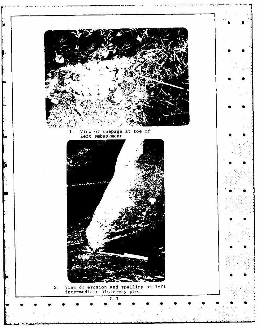
inspection. At the jgnction of the left endwall 0and its downstream 90 return wall, seepage on theorder of 2 gpm was observed through a void in theconcrete. Approximately 20 feet to the left ofthis point, a second small seepage of approximately0.1 gpm was detected at the toe of the embankment.The water was clear with no evidence of soil Bparticle movement.
3-1
• .-. .°. - °. • -... .,-. ...- , ' .. . "k° .
. '. ' ". - \ %. . -. , . . . . . . . .. . . . . . . . . .,.. . . . . .-.. . .L.. . . .".. . ". ".. .. .

(2) Spillway
The surface of the spillway exhibits minorsurface erosion which is not detrimental to thestructure. A vertical construction joint locatedat approximately mid-length of this structure anda horizontal construction joint located over thefull length of the structure approximately 6 feetbelow the crest are slightly open. These openingsare, however, not detrimental to the safety ofthe structure.
(3) Buttress
The buttress which separates the spillwayfrom the sluiceways has been subjected to erosion,spalling, random cracking and efflourescence andhas an open horizontal joint. A minor spall withassociated efflourescence is located at a verticalconstruction joint 3 feet upstream of the spillwaycrest on the right side of the buttress. The 0balance of this face of the buttress exhibits nosigns of cracks or efflourescence. The left sideof the buttress exhibits considerable randomcracking both upstream and downstream of the adja-cent sluiceway. A vertical joint approximately5 feet downstream of the sluiceway has beenrepaired with epoxy mortar. The upstream end ofthis buttress is eroded to an elevation approxi-mately 5 inches below the spillway crest. Thiserosion is approximately 6 inches high and 2 inchesdeep and extends around the end of the wall. Sur-face erosion is evident downstream of the sluicewaysup to 4 feet above the concrete sill. The erosion,spalling, cracking and efflourescence may be attri-buted to alternate freeze and thaw cycles combinedwith moisture penetration into the concretesurfaces.
I 0
(4) Sluiceway Piers (Photo 2)
The downstream end of the base of the rightpier is eroded and spalled and its sidewalls sufferfrom minor surface erosion, random cracking andefflourescence. The surface erosion is evidentup to 4 feet above the sill. The upstream noseof this pier is eroded from the spillway crest to apoint 12 inches lower.
3-2
U• .W W W 9 0 0 0 .

The surface erosion may be attributed to cavita-tion and the random cracking and efflourescenceto alternate freeze and thaw cycles combined with 0 -moisture penetration into the concrete surfaces.
The left pier displays minor surface erosionon its sidewalls and a crack at its connectionwith the concrete service walkway. Surface ero-sion of its upstream nose is similar to the right 5 Spier. The surface erosion may be attributed tocavitation and the crack to shrinkage forces.
The concrete sill below the sluiceway outletsexhibits minor surface erosion.
I S
(5) Right Endwall
Inspection of the right endwall revealed avertical crack upstream of the spillway which hasbeen pointed with epoxy mortar. Minor hairlinecracks with traces of efflourescence are evident I Sdownstream of the spillway.
(6) Left Endwall (Photo 3)
The inspection of this endwall was divided ..into two phases which consisted of conditions Iupstream and downstream of the sluiceway stoplogs.
The portion of this endwall upstream of thestoplogs exhibits random cracking with minor efflour-escence. Patching repairs with epoxy mortar have
n been carried out immediately upstream of the stop- " Slog guides. The repairs are in good condition.
The 900 return of the endwall upstream of thesluiceways is in good condition. It was noted thata horizontal and a vertical construction joint arewell sealed. There is no evidence of cracks, spalls I Sor efflourescence.
The portion of this endwall downstream of thestoplogs was refaced with a mortar-stucco finish.The original wall finish is not visible. However,the surface finish of this wall exhibits random I Scracking over 75% of its face.
3-3
w w U U S U U U U U U U S U U S S
In addition to the foregoing, a horizontal(longitudinal) crack, located approximately 4
* feet above the sluiceway outlet sill, exists *over the entire length of this wall. Spalls anddiagonal and random surface cracks with a highdegree of efflourescence are prevalent over thelast 10 feet of the endwall. A void is located inthe plane of the longitudinal crack and is approxi-mately 6 inches long, 4 inches high and 6 inches *
- deep. It is apparent that the horizontal crackis the location of a "stuccoed over" constructionjoint. Seepage through the endwall has causederosion, spalling, cracking and the high concentra-tion of efflourescence.
The 900 return of the endwall downstream ofthe stoplogs has sheared and translated away fromendwall by approximately 1.5 inches. Inspection ofthe opening revealed that this return wall is notstructurally tied to the endwall and that the wall
r" is 12 inches thick without any back batter. The *base of this wall and the end of the abutment areeroded, with seepage flowing out of the void. Theerosion covers a surface area of approximately 12inches by 18 inches and is 12 inches deep at its - "greatest penetration. The seepage was in the
* range of 2 gpm. The displacement of this wall may .be attributed to active earth pressures, and tofrost action to a lesser extent.
(c) Appurtenant Structures .
(1) Concrete Walkway
The concrete walkway is in good condition.
(2) Safety Railing
Two top horizontal rails approximately 15feet in overall length are missing above the sluice-way openings. The balance of the rails are ingood condition.
(d) Reservoirp 0
An examination of the reservoir shoreline revealedno evidence of movement or other instability. No signi- .
ficant sedimentation exists behind the spillway. Obser- "vation of the surrounding area showed no evidence of work . .
in progress or recently completed which might increasethe flow of sediment into the pond. *
3-4
. . .". ". "

.° .
Additionally, there were no changes to the surroundingwatershed which might adversely affect the runoff char-acteristics of the basin. There is considerable perma- 0nent development along the south shore of the pond.
(e) Downstream Channel (Photo 4)
There are no downstream conditions which adversely- affect the operation of the dam or which pose a hazard
to the safety of the structure. While the road bridgejust downstream of the dam does create a hydraulicconstriction, its existence has no detrimental effecton the structure, especially in light of the dam's limitedoperational capacity. Some maintenance of the down-stream channel is necessary, as it contains considerabledebris and overhanging trees which could become obstruc-tions to flow during a flood. While the two downstreamrubble training walls are in generally poor condition,they pose no significant problems for operation of thedam.
3.2 Evaluation
As mentioned previously, the Trickling Falls Dam is inFAIR condition. Because most of the dam's major componentsare readily accessible for examination, the visual inspectionprovided a satisfactory basis for assigning a condition rating.
3-5
3-5 0 S S ..-'S.0 .. 5-.-
• . . . . -- . .
. . . . . . . . . . . . . . . . . . . . . .. . .. .-.. .-.. . .

S O
SECTION 4 - OPERATIONAL PROCEDURES
i 4.1 Procedures a
As mentioned previously, a dam tender from the NHWRBvisits the dam at least weekly and reports water levels back .
to the Board's offices. The Board's engineers, in turn,direct any operations deemed necessary. The pond is drawndown approximately one foot in late summer or early fall inanticipation of fall storms and spring runoff.
4.2 Maintenance of Dam
The dam tender also inspects the condition of the damduring his visits and periodically files a written reportwith the Board. The engineers then initiate whatever actionsare deemed necessary to effect repairs. Additionally, a staffengineer inspects the dam at least annually.
4.3 Maintenance of Operating Facilities* S
The procedures outlined in subparagraph 4.2 apply tosluiceways and stoplogs also.
* 4.4 Description of Any Warning System in Effect
j No formal warning system exists for this dam. .
4.5 Evaluation
While the dam is in overall fair condition, the largenumber of minor deficiencies indicate that increased attentionto routine maintenance is warranted. Due to the absence of m .any real downstream hazard, the lack of a formal warningsystem is not a significant problem at this time.
4 -
4-1
* 0
..................................

4
SECTION 5 - HYDROLOGIC/HYDRAULIC
12 5.1 Evaluation of Features 0
(a) Available Data
" .* The primary data source for Trickling Falls Damis the records of the NHWRB. These files containconstruction plans showing the sizes of the original 0dam and the subsequent major alterations in 1940 and1962. Additionally, several pages of hydraulic and hydro-logic calculations for both structures are also available.These data are supplemented by two 1941 reports by the
- New Hampshire Water Control Commission entitled "Dataon Reservoirs and Ponds in New Hampshire" and "Data on 0Dams in New Hampshire."
(b) Experience Data
According to the records of the NHWRB, the highestwater level recorded at Trickling Falls Dam since its 0
reconstruction in 1962 is approximately 2 feet abovethe brass pin during a storm in 1973. This levelequates to a water surface elevation of approximately116.0 feet MSL which probably produced a discharge over
p the dam on the order of 500 cfs.
(c) Visual Observations
Trickling Falls Dam is an earthfill structure witha concrete gravity spillway and outlet works. The damhas an overall crest length of about 250 feet. The top
n width of the dam is variable with a minimum width of 0about 15 feet.
The dam contains a 34 foot long concrete ogeespillway and a three bay sluiceway with stoplogs havinga total effective width of 15.5 feet. Two of the baysare 5.0 feet in width while the third is 5.5 feet wide.The spillway crest height is about 7.5 feet above thestreambed and 4.5 feet lower than the top of the dam.Pond levels may be controlled to some extent by varyingthe height of the stoplogs. Two of the sluiceway bayshave permanent concrete bases two feet lower (El. 111.7)than the spillway crest. The third bay may be opened Sall the way to the base slab of the structure at anelevation of about 106.2 feet. At the time of theinspection, all stoplogs were set at the same heightas the spillway and the pond level was approximately " .
0.5 feet below the spillway crest. With the exception* . of a small amount of leakage between the stoplogs, there
was no discharge through the dam.
5-1
* W W W W W W W W 0
.:- ... ". . . ..".". ." ,.-.. " '' ": - ". -. -. .. . ..: , . -. , . - " ". . .", . . , .. ,.
.' .: : :-_ . . __ __ . - .-- . - - . . .= '- . .. . . . . . . . . . . . . . . . . .

4 B S
Just downstream of the dam is a constrictioncreated by a road bridge. The highway embankment is ata slightly higher (about 0.5 feet) elevation than the dam ,spillway and the bridge has a 17.0 foot wide clear span.Beyond this bridge the stream resumes a normal channeland is unobstructed, with little development in the ...-.
immediate vicinity.
(d) Overtopping Potential
The hydrologic conditions of interest in thisPhase I investigation are those required to assess thedam's overtopping potential and its ability to safelyallow a large flood flow to pass. This analysisrequires using the storage and discharge characteristicsof the structure to evaluate the impact of an appropri-ately sized Test Flood. The available discharge capacitycalculations included in the NHWRB records were not usedsince they predate the current configuration of the dam.
Guidelines for determining a recommended TestFlood based on the size and hazard potential classifica-tion of a dam are specified in the "Recommended Guide-lines" of the Corps of Engineers (COE). As specifiedin these guidelines, the appropriate Test Flood for adam classified as INTERMEDIATE in size and LOW inhazard potential is between the 100 year flood and onehalf the Probable Maximum Flood (PMF).
The magnitude of the 100 year peak inflow toPowwow Pond is estimated using a regression relationshipprovided by the USGS in Water Resources Investigations78-47, "Progress Report on Hydrologic Investigations ofSmall Drainage Areas in New Hampshire." This equation,which uses the drainage area, main channel slope andthe 24-hour, 2-year frequency precipitation to estimatepeak inflow, yields a 100-year inflow of about 4500 cfsfor the drainage basin.
The chart of "Maximum Probable Peak Flow Rates"obtained from the COE, New England Division, is usedto define the applicable PMF. For the 30.6 square miledrainage area above Trickling Falls Dam, which has atopography between "flat" and "rolling", the chart
* : gives a PMF flow of 900 cfs per square mile. Thisrunoff results in a total PMF of 27,500 cfs, or a one-half PMF flow of 13,750 cfs.
5-2
rS
0 wS S S S S S S S '.-

~1
The "Recommended Guidelines" suggest that if arange of values is indicated for the Test Flood, themagnitude most closely related to the involved riskshould be selected. Since the risk for Trickling FallsDam is midway within the LOW hazard category, a Test
* Flood of 7500 cfs is used as inflow to Powwow Pond.
The attenuation of the peak due to storage is- estimated using the procedure suggested by the COE
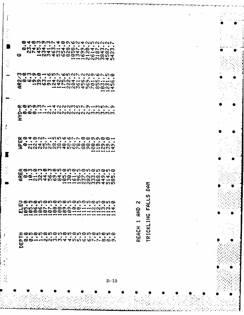
New England Division for "Estimating the Effect ofSurcharge Storage on Maximum Probable Discharges."The Storage-Stage Curve used for these calculations isdeveloped assuming that the surcharge storage available
- in a pond is equal to the surface area of the pondtimes the depth of surcharge. No spreading or increase Sin surface area with increasing depth is considered.The use of the recommended procedure shows that, inthis case, pond storage does have a significant dampingeffect on the magnitude of the peak flow since a 16percent reduction in peak flow to 6300 cfs as thecorrected Test Flood flow results. S
* .. The Stage-Discharge curve is developed by defining* .discharge as the sum of flow over the spillway and
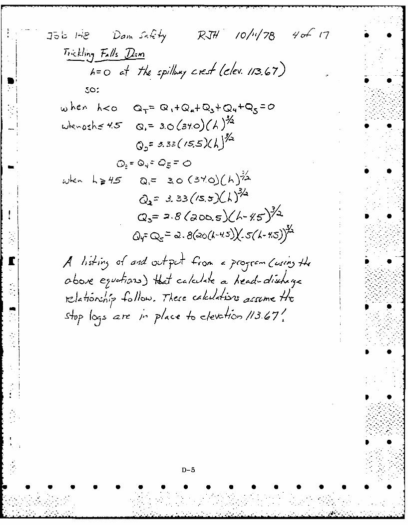
stoplogs, the flow over the dam crest and the flow overthe slopes at the end of the dam. These calculationsassume a stoplog height in all three sluiceways up toSthe level of the main spillway (El. 113.7) and thatthere would be insufficient opportunity to remove thestoplogs in an emergency. Paragraph 1.3 presents dis-
* - charge capacities assuming that stoplogs could beremoved. Application of the corrected peak Test Flood
* discharge of 6300 cfs to the derived Stage-Discharge. Srelationship results in a maximum stage at the dam of7.3 feet above the spillways (El. 121.0), which is2.8 feet above the crest of the dam.
5.2 Hydrologic/Hydraulic Evaluation
The results of the hydrologic and hydraulic calculationsindicate that the outlet capacity of Trickling Falls Dam isinsufficient to pass the appropriate Test Flood without signi-ficant overtopping. This conclusion is based on a likely,but relatively low outlet capacity condition with the stop-
* logs in place.
5-3
S
* S S S S S S S S S S 5 5]

Even if all stoplogs could be removed in the event of asevere storm, which might be difficult under the present oper--i-ating policy, the Test Flood would still result in the dam 0being overtopped by more than 2 feet. The maximum capacityof this outlet without overtopping the crest of the dam is .-
about 1500 cfs with the stoplogs at the normal pond level andabout 2200 cfs with all stoplogs removed.
- 5.3 Downstream Dam Failure Hazard Estimates
The flood hazards in downstream areas resulting from afailure of Trickling Falls Dam are estimated using the pro-cedure suggested in the COE New England Division's "Rule of
- Thumb Guidelines for Estimating Downstream Dam Failure Hydro-graphs." This procedure accounts for the attenuation of dam I Sfailure hydrographs in computing flows and flooding depthsfor downstream reaches.
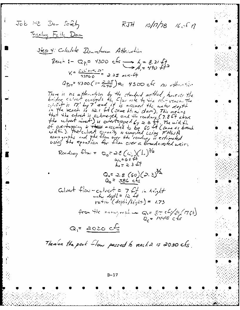
For these calculations, it is assumed that the damfails with the pond stage just overtopping the dam crest atEl. 118.2. This level corresponds to a height of 12.0 feet Sabove the stream bed. For an assumed breach width of 60feet, the resultant peak discharge due to dam failure is 4300 . .cfs.
Downstream of the dam there are essentially three reaches[ pertinent to these calculations. The first reach is 200 feet
in length and includes the region between the dam and theroad bridge. The second reach extends from the bridge to apoint about 500 feet downstream where the stream widens con- -
siderably. The third reach is a large flat swampy area withan estimated floodplain width of 1000 feet.
The attenuation of the dam failure hydrograph throughReach 1 is determined largely by the constricted channelopening through the road bridge. This embankment is a signi-ficant one that would be overtopped by the flows released,but because of its paved surface would probably not fail asa result of overtopping. Since the distance between thestructures is so small, the pond stage may be applied at thebridge to determine the flood flow passing on to Reach 2 asthe sum of the flows through the bridge opening and the flowover the roadway embankment. This calculation indicates thatthe peak dam failure flow would be reduced from 4,300 cfs to2,030 cfs in passing through this constriction. S
5-4
.. , -- ..-.-
* S S S S S S S S S S 5 5 0 5

Downstream of the bridge in Reach 2, a flow depth ofabout 6.4 feet would develop with very little additional atten-uation of the flow. One home located just below the bridge, - =appears to be the only structure that might be endangered. .This structure, however, is located above the 6.4 feet of . .flooding depth computed for this reach.
In Reach 3 the large volume of storage available in theswamp area would further attenuate the flow and produce aflood depth of less than 5 feet. No structures that would 6be affected by this depth of flow are located in this area.
I--
W S
K S
5-5 ii: ii:: °
: ................................-...................... ....... ,:.° .- :..

SECTION 6 - STRUCTURAL STABILITY
6.1 Evaluation of Structural Stability
(a) Visual Observations
The extensive field investigations of the damrevealed no significant displacements and/or distresswhich warrant the preparation of structural stabilitycalculations based upon assumed sectional propertiesand engineering factors.
(b) Design and Construction Data
No design stability calculations are available.The construction plans contained in Appendix B, however, Bare quite detailed and would be of significant valuewere a stability analysis deemed necessary.
(c) Operating Records
The dam's operating records reveal no evidence of 'instability under past flow conditions.
(d) Post Construction Changes
The alterations accomplished in 1940 and 1962 .significantly improved the dam's stability by greatlyincreasing discharge capacity and by providing addi-tional mass to resist sliding and overturning forces. .
(e) Seismic Stability
" mThis dam is located in Seismic Zone No. 2 and,in accordance with recommended Phase I guidelines, doesnot warrant seismic analyses.
6-1
V V V V V V V U U U • • " ]

I S
SECTION 7 - ASSESSMENT, RECOMMENDATIONS
* AND REMEDIAL MEASURES * .07.1 Dam Assessment
(a) Condition
The Trickling Falls Dam is in FAIR condition at
the present time.
(b) Adequacy of Information
The lack of in-depth engineering data does notpermit a definitive review. Therefore, the adequacyof the dam cannot be assessed from the standpoint of .reviewing design and construction data. This assess-ment is thus based primarily on the visual inspection,past performance and sound engineering judgement.
(c) Urgency
The improvements described herein should beimplemented by the owner within two years of receipt ofthe Phase I Inspection Report.
[ (d) Need for Additional Investigation
No additional investigations are deemed necessaryat this time.
7.2 Recommendations
As discussed in Section 5, the discharge capacity of 0• - the dam is insufficient to pass the Test Flood selected
without significant overtopping of the dam. It is thereforerecommended that further hydrologic studies of the spillwayadequacy be made.
7.3 Remedial Measures
The Trickling Falls Dam requires the following operatingand maintenance improvements:
(1) Repair the erosion at the junction of the rightendwall and the right embankment and provide suitableriprap protection to preclude similar problems in the
* future.
7-1
.L ... ->- .,

(2) Clear both embankments of all brush and treesand institute a regular program of slope maintenance.
(3) Closely monitor the two seepage areas, pay- S 0ing particular attention to changes in quantity andturbidity. If necessary, institute remedial measuresto preclude damage from the seepages.
(4) Repair all deteriorated concrete surfaces andjoints.
0(5) Stabilize and repair the 90 return wall at thedownstream end of the left endwall.
(6) Repair the safety railing over the three baysluiceway.
(7) Trim or remove all trees and vegetation alongthe approach channel and the downstream channel whichmight become obstructions to flow in the event of aserious storm. Institute a regular program of removingdebris from in and around the channel areas.
(8) Monitor the condition of the downstream trainingwalls to preclude their becoming obstructions to flow.Repair or remove the walls if necessary.
(9) Train local municipal officials in the proper 5 0operation of the dam and provide them with the necessaryoperating tools. Such a program could decrease responsetime in pulling stoplogs in the event of an emergency.
(10) Institute a formal warning system during periods - .-of flooding. -. @
(11) Perform a technical inspection of the dam everytwo years.
7.4 Alternatives
There are no meaningful alternatives to the accomplish-ment of the above listed actions.
7-2 3 0
a 4P a 6 6 0 0 0 0 0 0 0 0 0 0

I S
IS
I..
I S
APPENDIX A
VISUAL INSPECTION CHECKLIST
p 5
S
irn I S
I S
I S
A-iI S
* S S S S S S S S S S S S S S S S
. . .

l S
INSPECTION TEAM ORGANIZATION
Date: September 21, 1978
NH 00440TRICKLING FALLS DAMEast Kingston, New HampshirePowwow RiverNHWRB 72.01
Weather: Sunny and warm
INSPECTION TEAM S S
Robert Minutoli Goldberg, Zoino, Dunnicliff& Associates, Inc. (GZD) Team Captain
William Zoino GZD Soils S S
Nicholas Campagna GZD Soils
Andrew Christo Andrew Christo Engineers(ACE) Structural
Paul Razgha ACE Structural
Richard Laramie Resource Analysis, Inc. Hydrology . -. .
Mr. I'aittu Kesavan of the NHWRB accompanied the inspection team.
S Sd
A-2
. . , a .a..., • .. -. ..... ...... ..... . ............. . . :

Trickling Falls Dam September 21, 1978East Kingston, NH1 NH 00440
CHECK LISTS FOR VISUAL INSPECTION
- AREA EVALUATED BY CONDITION & REMARKS 0 0
EMBANKMENT
Vertical alignment andmovement . No deficiencies noted S S
Horizontal alignment andmovement No deficiencies noted; top
width 15' +
Condition at abutments No deficiencies noted; rubble o Swall D/S of left abutment
Trespassing on slopes No evidence
Sloughing or erosion ofslopes or abutments Some erosion on upstream side S S
at junction with right endwall"embankment 8" lower than wall:some riprap has been placed
Rock slope protection Small amount on upstream sideat junction with right end- Swall
Unusual movement orcracking at or near toe None noted
- Unusual downstream OSseepa! -e Small seepage (~0.1 gprn) at
D/S toe of left embankmentapproximately 20 feet fromleft endwall; small seepage(,2 gpm) under intersectionof left endwall and D/S 90S
return wall: area near baseof rubble wall D/S of leftabutment is damp, but noidentifiable seepage pointswere noted
Piping or boils None noted
A-3
W 4P W • W 0. .
Trickling Falls Dam September 21, 1978East Kingston, N11 NH 00440
CHECK LISTS FOR VISUAL INSPECTION
I AREA EVALUATED BY CONDITION & REMARKS 0
Foundation drainagefeatures Plans indicate coarse grained
gravel drain under D/S end of'spil lwav
Maintenance of slopes Some trees and considerableheavy brush cover most ofslopes and make inspection
-" difficult
OUTLET WORKS
a. Approach Channel . Broad approach from pond:shoreline along approach isflat; slides unlikely
Bottom conditions Not visible: bottom coveredwith leaves
Rock slides or falls No rock in vicinity
Log boom None, but steel cable can beinstalled across spillway
Control of debris Small amount of debris sub-merged behind dam
Trees overhangingchannel Many trees along shorelineimmediately U/S of dl-
b. Spillway - . .r
Condition of concrete
General condition Good
Erosion or cavitation Minor surface erosion on spill-
4 way and on left buttress be-tween spillway and sluiceways
Spalling Minor spalling on left buttress
A-4• A-4
... .., -]

Trickling Falls Dam September 21, 1978East Kingston, NHi NH 00440
CHECK LISTS FOR VISUAL INSPECTION
AREA EVALUATED BY CONDITION & REMARKS I S
Cracking Some random cracking on leftbut t ress
Condition of joints Minor opening of one full I Slength and one full heightconstruction joint on spill- -way; open horizontal joint onleft buttress.
Rusting or staining None noted I S
Visible reinforcing None noted
Seepage or efflour-escence Minor efflourescence on right
buttress I S
C. Three Bay Sluiceway
Condition of concrete
General condition Good I S
Erosion or cavitation Severe erosion near bottom ofright intermediate pier: minor -
erosion over remainder ofright intermediate and over
- left intermediate pier I
Spalling Some spalling near bottom ofright intermediate pier
Cracking Random cracking over bothintermediate piers I S
Condition of joints Considerable erosion of con-struction joint between rightintermediate pier and baseslab
Rusting or staining None noted
Visible reinforcing None noted
A-5
* U U U U U U U U U U U U U U

Trickling Falls Dam September 21, 1978East King:ston, Nil NH 00440 5 S
CHECK LISTS FOR VISUAL INSPECTION
3 AREA EVALUATED BY CONDITION & REMARKS 5 S
Seepage or efflour-
escence Some efflourescence on both
intermediate piers .
Condition of stoplogs Good; minor leakage between
logs
:lheluatelV 5Qseured
( *nr.-per pr F) ) Locked in place
d. Endwalls
Condition of concrete
General condition Good except 900 return wallon D/S end of left endwall,
which has sheared and trans-lated away from enu>,all; base
of wall adjacent to abutmenthas eroded approximately 12"
3 deep over a 12" x 18' area •
seepage of 2 gpm through void
Erosion or cavitation None noted
Spal ling Some spalling noted over 10-, feet of left wall on D/S end
Crackin- Vertical pointed crack and
minor hairline cracks on rightwall; on left wall, somerandom cracking on U/S end' onD/S end of left wall, fulllength horizontal cracks atone location and random sur-face cracks over 75 of face
Condition of ,Joints No deficiencie.; nl o)tc
Rusting or staining, None noted 5 •
"" _-Visible reinforcing ... None noted
UA-6 U-0 0
• 0) W W 0 W W-0 W .0 W 0.

Tricklin, Falls Dam September 21, 1978East Kingston. Nil N" 00-4-10 I '
CHECK LISTS FOR VISUAL INSPECTION I
AREA EVALUATED BY CONDITION & REMARKS
Seepage or efflour- -escence Traces of efflourescence near
cracks on ri-lht wall: some onU/S side of left wall; high 0degree of eff1ourescence onlast 10 feet of left \,l1 (onD/S side
e. Walkway
Condition Good a
Safety railing 15 feet of top rai]- missing,probably removed to facilitateaccess to stoplogs; remainingrailing in good condition
I. 0
OUTLET CHANNEL (immediatearea)
Slope conditions 7 Downstream channel is broadwith heavy vegetation on
I both sides: old rubble training Swalls in disrepair
Rockslides or falls No rock in vicinity .1-
- Control of debris Some debris, including several
large tree trunks, in channel 0
Trees overhangingchannel Heavy overgrowth on both sides
which does extend over channel: ..-
some vegetation growing inchannel •
Other obstructions Concrete highway bridge some200 feet downstream createsa hydraulic constriction
Existence of gages None; water levels measured 6from brass plug on U/S faceat El. 114 + (MSL)
4. IA-7
W
.. W . . . . -
. . . . . . . .. . . . . . . . . . . . . . . . . . . . . . . . . . . . . . . .

Trickling Falls Datm September 21, 1978East Kin-ston. NH NH 00440
CHECK LISTS FOR VISUAL INSPECTION
AREA EVALUATED BY CONDITION & REMARKS
RESERVOIR
a. Shoreline
Evidence of slides None noted
Potential for slides Shoreline stable
b. Sedimentation Nnne noted
c. Upstream hazard areasin the event of back-
flooding Considerable permanent de-velopment along south shoreof pond
d. Changes in nature of
watershed (agriculture.logging, construction,etc.) None noted
r DOWNSTREAM CHANNEL
Restraints on dam"
operation None, given dam's limitedoperational capacity
-Potential flooded
area Only one home within floodplain for a considerable dis-tance D/S
OPERATION & MAINTENANCE* FEATURES I S
a. Reservoir regulationplan
- Normal procedure Maintain water at spillwaylevel during summer recrea-tional period; draw down 1 foot
in late summer or early fall . .
for flood control
A-8
•.°. . .. .
_~~~~~~~.......... .-. 2....-."...-... .. , ..... . .. . . •.. - ... ..- .-.. ,.-... -.. ...
Trickling Falls Dam September 21. 1978East Kingston, NH Nh 00440
CHECK LISTS FOR VISUAL INSPECTION
AREA EVALUATED BY CONDITION & REMARKS 0
Emergency procedures Permanent dam tenders couldpull stoplogs if necessary,but could be slow due tonumber of dams covered byNHWRB; no warning system inaffect
Compliance withN designated plan Generally satisfactory,bul
many complaints on file aboi!both low and high pond levels
b. Maintenance
Quality Many 0 & M type repairs areneeded at dam
Adequacy opertorDam inspected weeklyV byoperators and annual1ly' byNHWRB engineers
- S .. .. S
A-9
W W W a W 0 0 0 a a U 0 0 0 0 0
'- )- '. ." .<.
-.- . ." -
. .

APPENDIX B -
Page
FIGURE 1 Site Plan B-2
Plans of 1961 Trickling Falls 0 0Reconstruction B-3
Plans of 1940 Trickling FallsReconstruction B-6
List of pertinent records not S 6included and their location B-8
News release by the NHWRB datedJanuary 18, 1978 concerningPowwow Pond levels B-9
B-i1
. ,.. . .. . . . . . . . - - .°.

~. <2>z.
T'-4
~:.FIG. I
DATE~ SET17
SB-2

I-,-
'Il

K . - . - .
S
-
--.-.- - - - - -~
S
I'
ii -~
I -I 1. - S* I
I- I
- S
-~ - - -, :1 I
~5
- I:-~~ 't~ - I * - - I,
~v-. .. e4S
-. 5I- .. -*~
S
.- 4.
.5.;
I, i I
S
S
1~@1 ~u I.
1,' - - -~

-iI d
-2..•
' . • . I
a, . ... ..-
* 2 .
I. -A
* . . . '4. . - . . . . - ,,-,, _ . . .. .
. . . .. ... .. .... . .! 2
It
• .--- " - i. .. . . - - . . -, . ,. . " . .. - i - . _ . --:.- . , -2. .

alS
ii 2 L iVI> .
e5~

,AFP~'~flhIC:EI Ar (;ov~RNMrN r F ______________
~I ) 0 3U
9 I p'F.-N ,~(*
r~4~3I.
- 'F 4'
"-A-- - -~ &* ;'* .~'. '-, V
- Qrv* ..
C>
'I A7, ~ 4 iA ** 'F~'A
~ K -~
4 7~\f
2.~ '41
I-.~;' j *.
'5' -~ S
4'
.4.4
4 t-4 A
44 5
A
V A
Iv .:~
('I
/ .5 ~-40~
.1.- ~-1 ~Ljj
I-2"LA.-~ U
>" :~ -. ryX'.5
.5 - '4
~ A. I. 4I . I
I'..'
L .
- -* .- - 7 - . . -- - * - *. .. . - - -. - -.. - . -- .7. - - - . ..
The New Hampshire Water Resources Board, 37 Pleasant Street, S SConcord, N.H. 03301 maintains a comprehensive correspondencefile on the dam dating back to the 1930's. Included in thisfile are:
(a) Several pages of hydrologic and hydraulic calcu-lations for both the old and new configurations.
(b) A large volume of correspondence from upstreamand downstream residents concerning reservoirlevels and discharges.
(c) A 1941 report by the New Hampshire Water Control 0 0Commission entitled "Data on Reservoirs and Pondsin New Hampshire."
(d) A 1941 report by the same agency entitled "Dataon Dams in New Hampshire."
B-8
0@.
. •
. ..-K
p.• .- . . --- o
2 . . .-. .-.
. . . . . . . . . . . . . . . . . . . . .. . . . . . . . .". .. ".

Otatr zef Xna WazMP~irrWATER RESOURCES BOARD O 0, CONcoRD O3 30t
January 18, 1978
NEW S- REL EAS E
George M. McGee, Sr., Chairman of the New Hampshire Water Resources Board,
announces that at a Board meeting held on January 11, 1978 that it was moved,
seconded and unanimously voted, that the level of Pow Wow River Pond be maintained
to the level of the emergency spillway during the sumer recreation months. * S
This change is a result of the public hearing which was recently held in
East Kingston regarding the level of Pow Wow River Pond. In previous years the
"full pond" measurement was set at 5 inches below the "pin" which is set in the p
concrete abutment. The new summer or "full pond" level will be to the emergency
spillway crest or an increase of less than 3 inches in pond elevation. This -i
as requested by those who were in attendance of the public hearing. It should be
noted though, that no change is anticipated in the standard fall and winter draw-
down schedule. As a consequence of the requested action, a minor decrease is
expected in the storage capacity of the dam, hence an increased susceptibility
to minor change will occur. h
3 S
G.LAIG:GK:njk
cc: WS & PCC14 Dept. of Safety
F & G Department'anchester Union Leader A •Concord M!onitor
Senator Vard B. BrownBox 404East Har.pstead, NH 03826
Councilor Dudley N'. Dudley23 t;odman RoadDurhan, NH LI\ .F r'... ( R DIE
I S
B-E
P - .- W W 0

- --
APPENDIX C
SELECTED PHOTOGRAPHS
4 I 1

e ~-
POWO P~o
U US$$ ft.
14A
TC
4
CONCO BEWE OTS 07 N 0
GOLBEGZ0140 DNNCLIF ASOINC US.ARY EGIEE DV N W NGAN
GEOTECHNICAL COSLAT OPSO NiEr NEWTON UPER FALLS, M S.ATA.MS
NATIONL PRORAM O ISETO FNNFDDM
+ OVRIWPOO
APPEDIX PHTOS OCATON ND OIENTTIO
C, 2
VIC i.,.
'4AI
1. View of seepage at toe ofleft embankment S
2.~~~~~ ~ ~ ~ Viwo rso ndsaln nlf
inemeit Sli a pie
C-3
* S

0
3. View of translation of 900 return wall atdownstream end of left endwall and ofdeteriorated concrete on both walls
4. View from dam of downstream channel and road.bridge creating hydraulic constriction
C-4
-. ..°
...... " -- i .- - -

APPENDIX D
HYDROLOGIC/HYDRAULIC COMPUTATIONS
D- 1
w w w w 0 w a

?AJ D~z a~-/'f/
Te/1;
0.. 7Z
/1~ Slp 75r~~ -Nrc- ,,
-. 105 \05 .Z.7a .
7 'j~lJ ~k tlei a Mei p i Lcl /Ai d ,lk4 a
0'-j t'j 4ao~ 713 7SO4'(
D-2
* 0 0 S S S 0 0 0 0 0 0 0 0 0 0 S
/~r
4A0,6~
~§ .. ,
9i 7' -0Ae'
/
Zy.
t
- C
1-oftI
I,-j . ..
AM* '-~ ~ (A
71 S0

'1'j
-7--
-~~ 11Vo'-\< . 0 (f7 M'
L)I\/JJ LCT. FS,,4r
*D-
A=O5 v/, A-3,A)
:.- o e,., <o +T Q ,,Q4- - + 5 0 ::--:--
G ..3.0 (3,O)( ;,0 0
S S
3, 33(
I S O I•'::- .:-:::
(cp
A . , . -? . -: .
-. . . o
D-5-

C 0L
* 00IL -jw
C.) W
0 00 -
-. 1-- C3 L U)
-~~ Z *04',
<C 1- in
<C L L1
-4 wU. -4 zJ r- 0 w 4)CUJl
z w #A 4' IAL-i.1 I L .
E) XL U w If MZi M- ix (n (n CC -0 A
=U IL :3 Id 3- V4C00- 0- -. 0) 0O 3 f)lc -_i-i- - L -CI - %_ <- .-w .~C 2 -4 M *& C5 - 0 - CD- OtI.
~~w Cin vnC - POIk~W W aom s oi an RA .- 'l, W S 0wu u... CDCC CD _j V ) U)' : (x.j Ei 4m W- - .4 L. V-4J0 u- 4-M +f- Sx 03f)
f.- UfOJ )x =z 4bJj c~i VfI Da=CwL UC. Li) 0.4 - a 0- 1. - - - 3 I,-- W-4 V)(j C +
:iA. Iz ' LaJ m V) 110 )
~~~~~ air1- 1W -IJ- 1-~9 ev *--L
D-6

-o •
* •
w0
7 ') Q)w*" % ( V % " C DJ V) V'L) W " N OD-
U)c) w D
U Ii S']~0 x
V) U)Q
r 0 ~ -jS0o,, --. ,, -4 -4, r-,4 ,,.Dl-l- " ,Xl O,, r' ...-.. 4i
U) L
aI.,
IL.
L7L .0 --
UUU a,. ,,. CD I ) ) ) 1 D () 0 " I C- 1 CD W) D 0 CD InJ CD ) CD ( J (S In CD 0 CD
o) U)wO ('-w
ID-7
.' z o.I,- 9 ) ) ) )) () () C) 1)> .. "C.),, UJ >I' 0) t' " " C)I19 I'" >Il9 I" ) -?
................................... .. ........................

D-8
1~ ~ UiL22 A: J~ I ~ ~
-- -~ -----v---* .*II* __ - - J -~ ~-
I______ I FT~P ------ ~-- *'i
_____ ______ - - -.- ~-..-~- 2....~.. -
* ___ I-~---r '' I
* __ ~~-~., .9 - I,
* . m~,- _____ - .1
-~ ~ -- - .4
I . - -- _ _ _ . '
* * ~ -- *~*~-- -. -- ~1~~ __-I ____. ,.. ........-.-42.-~ . _____ ____
. , ________ ____- -v---- - ------. . ---- ------- ~ - -- ------ ---------.. S -
_______________ I - ---.-- - ---- , - - -- -~---I----.-- --- - ----- _____ -
______ I __ ----9-,-----________________ ________________ _____ -.----. -.--- .-- . .-----.--- ,-
* . ____*~ II * I *~ I
__ - . ~ -
______ ______ -- .-.-- .2......,...~ ~V ' --
* I * .
(-
II -;
'-1,.
- . . . I . ,- .~ -~ .ffiz.L ~
* -in' I
'I
L -- ~ -
* 2L...z .~
I' ,__j~I. ~-
__ -'I'll S Sm - ___
Ii I -~
FP77 *I1I
,1-
S S
-i-i.~. _______ __
* S S S

.J4, ~93 27~ i;:~4~ ,/~) // 76 ~ 0 0
/2k//S
* S~r~eS~~5c ?e/~A5'Jr:SL~4~ ,4~ I p~'J (Ac PU> ~~ ~L1~ -
C f/\ ~ /-, ~ / ofr rU1~O~- fro~'ces ~ Ill
1v4'~-,'
cT (/i'cJ 'j(sc~o'~~ -
~2S$
L~ I-C.4 /~- S S
i4o'fmfri~e z~> 0/8
6 5 6
S
S S
~ ~
- S S
C S S-~
-~4( ((~J~
* S S
A S S
D-9
* 6 5 S S S S S S S 5 5 5 S S S S

D-1O1
1V _ _I__II
_ _ I N t I
I V I. i1 -
-- -- -I -------~
;),40

75D 7.4, 60,'- 4 ,~d&S0 (a 0 0. 7 .2
7•: -2'- .
jD-1
1 @ Q- 7&0 0 0 -- y,&,. b o" 7. 6'o --,
,2 Q ,- $s35s s -4z yrv<,,'i A -- 7./7 ,
=I 75.' i - 60/0 c-i,•
-i ~,,,,o.c. (z . Dc.' 3 - /.30o ,frc ! .:._-
5; t 7' "
I, - o'(, ,..o - ,
- :::::::::::::
.. 'I .-.I

~0 ~ A~ J~J7 ( /i~' / S
k,-vv), f7/4u a7)l-,Fc; / ,/v
3~~s~ ~~)~ Q~"2~44 /Vn&~d-a
-lzov r Zoc' >~
C/-'>= leLCO-4~ J~ .A ~J/ 1 J
ct~~~~~40 (6. 4Tk-L t /4 57/j/
= A/o-~/ '- S~jv),--I<o/7 7'
L r- - I/l-L i \)3e4
I, D-12

)V / tL/
fvcf
A)~
C- -- ~ -/soo, ,04#S
C. ~~0& 0,5,'~L
0 0 oo

-~ Vt
I- t
C$4 4 it.
SES
,~ ~ V4.: 4C..0
s-', tli
B ' M 'k,?C ~ LC~I
I
-pr .6$ ~ ~ ~ /r\ .1 4 J ~ .- - 'v
j~~-v~o4 Q.. '4, '
,~. *S * S S .000 0230
w ~ ~ C C rl: Q r r' t r; ar. r4 N ' nc0
NN)'.r-iN -- NN MV0
M C .M Ch Cs aW * N .W U- \ P- N N Ol %N.
N~~~ ~ ct Vt O- (\j OD W N' WI CD U - L m 'I) M-.- M1.
-4-4-4
W. CD V~ ) Ch M r- V IN N M ) r- ON M- f'0 r- N O
Q CDCDC -4 N N~ (N C'1 N\ (\ N N\ kN rf) M~ M) M~ M~
N Q % C N * N 4 Id IC) V0. U- Q) r- 03 a', IM No 0%
(.. Mo V4 N 0 2- OD) CS M0)0)0)0)) CO re)0 C O V OD
=> CD rW o) CD V ) CD nC o U.) LnC I A b) ab L) WD wA w NJ
_j ) U- w~ kD N G OD a a CD C 1.N Ni (V m) 0 m v ~ '- I.
u )w-
N .
uJ~~~~~~~~~D 15 a*aaaaa

*0.
CD (h M N M 14D~t N N% rN r- CO Q0 V rif) r9 P) to-1 W %- N N
.wrs s-I0 (nol-4 MN NN ChNW WO W M0.U D0N
0-4 -4 -4-0 -4 N~ N~
w 0 N Nqo 0% n k I' MJ N N M V0- N n~ W P- W N 0 N0- M4 M
W rl 1-4 C 10- (%J (h0 OD O) O. O C~ D 0'1NV- f' M. r - n C
w m 0 4 h Nh N (r a,, ch CD CD 0i C) OD) 00 0 0 N 0 0 m0m m 0 mVr 4%4 - - -4
G) ) SCDCW) CD In) G) In CD N O CD0 V0) (% ) CD 0 CD 0 NV) IM ) 0
0. ~ ~ ~ -4--- 0 0 N4 N~ N) M~ M 'rt Vt IW) Is)'01.0:Ia G ; 0
LU)
*D 1
. . . . . . .
C)o L :-,KB ] J- /07728 <f r7S .
* J~p y c• Jk-. .-
) Lr, .I, a/_ 4,"o
4 030ex. S-/ rj.-qc3.,
• , , . ./ . ,,-
•- 4< ::)- <r- / -.,-..-.,--.-.-
- t,<.k- !: c.-,Y , c (7,.$+,./
4 6~ ~ ~jmF-M- A'
= o .o y8.
att
! .4. _ S
::" ~~~~~D- 17:: :::: ::::-
c.. S"m:-:::
:::: -_-:: .:-::::: .::': _ ::; : .. .- -: .-: " .: : .-: ." ... 2" ..: -:: -: -.:.:.:_-2. ....= . -: -, :- .

Y OO,/273)~
7ZT- -= c?,.27c 4 -A.
V 0
7,V Y 740
Y3- .5 g-(
~ -- 1775' c A V.7
D- 18

APPENDIX E
INFORMATION AS CONTAINED IN
THE NATIONAL INVENTORY OF DAMS
E- 1

0 z
Go
oo~ LI%
00
-z
1C - Z
4 z
U I.r
C- i
cc Cfo z3
Lrox 0 0
C4 , w 0 c
I- I~. IuJ~ S ,In~.< In
'22 - aI IuJ *u.0>0 +-i i V'
o J o~i 0 z z -
I I jo~ cf_~Z~I - ~ u

8-85
DTIC