rcra closure guidance for treatment, storage, and disposal facilities
TRANSCRIPT
STATE OF CONNECTICUT BUREAU OF WASTE MANAGEMENT ENGINEERING & ENFORCEMENT DIVISION 79 ELM STREET, HARTFORD CT 06106-5127
TEL. (860) 424-3366 TOLL-FREE (RCRA Questions Only): 1-888-424-4193 www.dep.state.ct.us/
DRAFT RCRA CLOSURE PLAN GUIDANCE FOR TREATMENT, STORAGE AND DISPOSAL FACILITIES
CONTAINER STORAGE AREAS AND TANK SYSTEMS
PREFACE
This document was developed by the Department of Environmental Protection to guide all persons involved in preparing and reviewing closure plans for RCRA facilities used to store hazardous waste in containers and tanks for greater than 90 days. These facilities are subject to the provisions of the Connecticut Hazardous Waste Management Regulations and 40 CFR Part 265.
This guidance is primarily for clean closures. If during the site characterization process it becomes necessary (for reasons discussed in the guidance) to close the regulated unit as a RCRA landfill under 40 CFR 265 Subpart N, additional regulations and guidance may apply.
Facilities which have operated under interim status and are now closing, and facilities changing from interim status to generator status, i.e. less-than-90-day storage, will be the primary users of this guidance. Although not subject to the same closure requirements, RCRA generators could also use this document when closing.
This guidance can be used by the facility to prepare a first-time closure plan submittal, or will be used as a generic Notice of Deficiency (NOD) by the Department of Environmental Protection (DEP) in lieu of a detailed site-specific NOD. It is intended to insure a measure of consistency for all RCRA closure plans. Ultimately it will minimize the number of DEP-comment/facility-response cycles, thereby reducing the review and approval time.
DEP reserves the right to change the contents of this guidance.
Closure plans prepared using this guidance may still need to be modified.
The DEP welcomes input and/or constructive criticism regarding this document. If you have any questions, comments or suggested changes that will improve this guidance you may contact the DEP staff person currently assigned to your site.

2
TABLE OF CONTENTS
PREFACE.....................................................................................................................................1
INTRODUCTION........................................................................................................................4
Figure 1: Recommended Review and Approval Process ..........................................5
CLOSURE PLAN PART 1: FACILITY INFORMATION AND SITE CHARACTERIZATION WORK PLAN...................................................................................7
I. FACILITY INFORMATION ............................................................................................7 A. Introduction..................................................................................................................7 C. Environmental Setting.................................................................................................8 D. Description of regulated units.....................................................................................8 E. Part A Status ................................................................................................................9 F. Other Sources of Contamination................................................................................9
II. SITE CHARACTERIZATION WORK PLAN .................................................................9 A. Constituents of Concern ............................................................................................10 B. Identify All Potential Human Exposure Pathways .................................................12 C. Identify the Presence/Absence of Contamination Requiring Remediation ..........13
Figure 2: Determination of the Presence/Absence of Contamination Requiring Remediation ..................................................................................................................15
D. Determine the Extent of Contamination in Structures and Soils ..........................16 Figure 3: Illustration of an Idealized Contaminant Migration Pattern in the Unsaturated Zone .........................................................................................................17
CLOSURE PLAN PART 2: RESULTS OF SITE CHARACTERIZATION PROGRAM AND PROPOSED CLOSURE APPROACH ..........................................................................20
I. SITE CHARACTERIZATION SAMPLING AND ANALYSIS RESULTS........................................20 II. PROPOSED CLOSURE APPROACH.......................................................................................21 III. DEPARTURES FROM SITE CHARACTERIZATION WORK PLAN ............................................21
CLOSURE PLAN PART 3: REMEDIATION, VERIFICATION, QA/QC, CERTIFICATION.....................................................................................................................22
I. CLOSURE PERFORMANCE STANDARD ...............................................................................22 II. REMOVAL AND DISPOSAL/DECONTAMINATION OF WASTE, EQUIPMENT, STRUCTURES AND SOIL 22 III. REMOVAL AND DECONTAMINATION OF TANK SYSTEMS...................................................24 IV. QUALITY ASSURANCE AND QUALITY CONTROL PROCEDURES (QA/QC)..........................25 V. CLOSURE SCHEDULE.........................................................................................................25 VI. FINANCIAL ASSURANCE/CLOSURE COST ESTIMATES........................................................25 VII. CERTIFICATION OF CLOSURE ............................................................................................26 VIII. APPENDICES......................................................................................................................26
ATTACHMENT A: WIPE SAMPLING PROCEDURE.....................................................27
ATTACHMENT B: CALCULATION OF WORST-CASE AIR CONCENTRATIONS.28
3
ATTACHMENT C: SAMPLING AND ANALYSIS GUIDANCE ....................................29
TABLE 1-1: ANALYSIS OF WASTE FOR APPENDIX IX PARAMETERS ......................................29 TABLE 1-2: ANALYSIS OF SECONDARY CONTAINMENT STRUCTURES FOR APPENDIX IX CONSTITUENTS .........................................................................................................................30 TABLE 1-3: DEVELOPMENT OF BACKGROUND VALUES FOR MEDIA CLOSURE CRITERIA .....31 TABLE 1-4: SITE CHARACTERIZATION - DETERMINATION OF LATERAL EXTENT OF CONTAMINATION ......................................................................................................................32 TABLE 1-5: SITE CHARACTERIZATION - DETERMINATION OF VERTICAL EXTENT OF CONTAMINATION ......................................................................................................................33 TABLE 1-6: HAZARDOUS WASTE DETERMINATION - EQUIPMENT, STRUCTURES, SOILS DISPOSED OF OFFSITE ...............................................................................................................34 TABLE 1-7: POST-DECONTAMINATION SAMPLING OF SOILS.................................................35 TABLE 1-8: POST-DECONTAMINATION SAMPLING OF TANKS AND SECONDARY CONTAINMENT STRUCTURES WHICH ARE CONSTRUCTED OF POROUS MATERIAL .............................................36 TABLE 1-9: POST-DECONTAMINATION SAMPLING OF TANKS AND SECONDARY CONTAINMENT STRUCTURES WHICH ARE CONSTRUCTED OF NON-POROUS MATERIAL .....................................37
ATTACHMENT D: GUIDANCE ON DEVELOPING MEDIA CLOSURE CRITERIA38
I. GUIDANCE ON DEVELOPING MCCS BASED ON BACKGROUND SAMPLES ..........................38 II. EXPRESSION OF MEDIA CLOSURE CRITERIA AND RELATED ANALYTICAL DATA UNITS........38

4
INTRODUCTION
This guidance document recommends that the nature and extent of contamination be determined and included as part of the closure plan, prior to approval. In doing so, the remedial measures will be based on an accurate assessment of the problem and post-approval modifications due to "unexpected events" will be minimized. CTDEP has developed a closure process designed to achieve this result.
The following Figure 1 presents a recommended closure process which describes performing site characterization (nature and extent of contamination) prior to closure plan approval. In this process, the closure plan is submitted in three parts; CTDEP reviews and comments on the first two parts (if necessary) and then approves, disapproves, or modifies the 3-part closure plan. This 3-part process is not required by regulation but we have found that closure plans prepared in this way reach final approval in a more timely manner. In addition, because the site is more accurately characterized, post-approval "unexpected events" are minimized, thus avoiding a prolonged closure plan modification process.
Closure Plan Part 1 is a work plan to characterize the nature and extent of any hazardous constituents released by the regulated unit. In addition, a general background of the facility and its environmental setting is provided. CTDEP will review Part 1 and will provide the facility with further site-specific guidance if needed. Once Part 1 is completed the work plan can be implemented.
Closure Plan Part 2 is then submitted to summarize the site characterization results. Part 2 will also contain a proposal to close the unit "clean" or as a "landfill" based on the site characterization results. CTDEP again reviews this document and provides input prior to receiving Closure Plan Part 3.
If clean closure is proposed, then Closure Plan Part 3 will be submitted which will include a plan to remove or decontaminate waste and/or waste residues and to verify that decontamination was successful. It will also include the remainder of the required closure plan contents, e.g. schedule, cost estimates, contents of closure certification report.
CTDEP will approve of the completed 3-part closure plan after a 30-day public notice period.
CTDEP prefers that Part 1 of the Closure Plan be submitted in a loose-leaf 3-ring binder that is large enough to allow the addition of Parts 2 and 3 of the closure plan.
This guidance is organized into three sections which cover the requirements of Parts 1, 2 and 3 of the closure plan.
The 3-part closure process is most applicable for sites which are actively closing. We recognize that this process may be impractical in certain situations and the following are recommended approaches for some common closure scenarios.
1. Closure Plan On File at CTDEP and Awaiting Review by CTDEP: Many plans were submitted to CTDEP before this guidance was written. We recommend that these plans not be revised until a CTDEP staff person is assigned to review the plan; at that time we may request that the 3-part process be used.

5
Figure 1: Recommended Review and Approval Process

6
2. Closure Plan is Currently Being Reviewed by CTDEP: CTDEP will ask that the 3-part closure
process be used.
3. Closure Plan Being Written or Revised to Correct Deficiencies Found by a CTDEP Inspector: We recommend that the closure plan be written in a way that will adopt the three-part process when closure takes place. When the plan is reviewed by the CTDEP, we will ask that the 3-part process be used.
4. Closure Plan to be Implemented Voluntarily and Without CTDEP Approval: We recommend that closures which must be implemented prior to CTDEP approval follow the 3-part process even though DEP can not provide any input. However, when CTDEP reviews the plan revisions may be required.
5. Closure Plan Included With Part B Permit Application: Closure plans to be included in permits should follow the guidance to the extent possible without performing site characterization. The permit conditions imposed by CTDEP may specify that the facility must follow the 3-part process (to include CTDEP input) at the time of closure. This should be discussed with the permit writer assigned to your facility when the application is reviewed.

7
CLOSURE PLAN PART 1: FACILITY INFORMATION AND SITE CHARACTERIZATION WORK PLAN
Closure Plan Part 1 includes a general background of the facility and its environmental setting followed by a site characterization work plan. The work plan can be implemented after CTDEP reviews Part 1 and provides site-specific guidance if needed.
I. FACILITY INFORMATION
The following closure plan requirements have been compiled from the closure regulations and closure checklists.
A. Introduction
1. State the reason for closing, e.g. property transfer, status change.
2. Cite applicable regulations, both state and federal.
3. Summarize regulatory events leading up to closure, e.g. RCRA inspections, enforcement actions.
B. Facility Description
1. Describe products manufactured at the facility.
2. Provide the age of the facility, prior use of the property and dates of all historic property transfers.
3. Describe processes which generate hazardous wastes and where these wastes were stored.
4. Provide a topographic map showing a distance of 1000 feet around the facility at a scale of 1 inch equal to not more than 200 feet. Contours must be shown on the map. The contour interval must be sufficient to clearly show the pattern of surface water flow in the vicinity of each closing unit of the facility. The map shall clearly show the following:
a Map scale and date,
b Surface waters including intermittent streams,
c Surrounding land uses (e.g. residential, commercial, agricultural, recreational),
d Orientation of map (north arrow),
e Legal boundaries of the site,
f Withdrawal wells, public and private,

8
5. All buildings and structures on site (e.g. manufacturing, office, closing regulated unit(s)),
C. Environmental Setting
1. Describe the land use within a 1000-foot distance surrounding the facility.
2. Provide groundwater classification at the site.
3. Provide locations of drinking water supplies within a 1000-foot distance surrounding the facility.
4. Describe, using existing data and literature, the local and regional geologic and hydrogeologic setting including description and depth to bedrock, depth to and flow direction of groundwater in all potentially affected aquifers, and a description of site stratigraphy.
5. Describe and provide a map of local topography including surface water bodies.
6. Provide a map of surface drainage patterns and location of storm drains in the vicinity of the regulated units.
D. Description of regulated units
1. Provide photographs of the regulated unit(s) to be closed. Clearly delineate all existing containment structures and exterior and interior components.
2. Identify regulated units closing and those remaining open.
3. Provide scale drawings of each regulated unit being closed including secondary containment structures, cross-sections, details e.g. sumps, drains, floor pitches.
4. Provide the design capacity (maximum inventory) of each regulated unit to be closed.
5. Describe the material of construction of the primary and secondary containment structures (e.g. steel, fiberglass for primary containment, and asphalt, concrete, aggregate, soil for secondary containment). If changed or upgraded any time during interim status period, describe and provide dates of changes.
6. Describe the floor coating and the date of application.
7. Describe all components and history of the "tank system" including:
a Dimensions, capacity and materials of construction of each tank,
b Secondary containment structure design and materials of construction,
c All ancillary equipment directly connected to the tank or secondary containment structure, e.g. piping, pressure relief valves, instrumentation,

9
valves, level sensors,
d Provide a scale drawing of the tank system, include the process flow,
e Provide the maintenance/repair/replacement history of the tank system,
f Provide the age of the tank system,
g Provide information on any spills which occurred during the life of the facility.
E. Part A Status
1. Compare all RCRA-regulated units presently on site with those entered on the most recently submitted Part A permit application.
2. If necessary, resolve discrepancies between existing units, design capacities, and waste types with that which appears on the Part A by modifying and resubmitting the Part A as a separate stand-alone document. A modified Part A must be accompanied by an explanation of the changes. Attach a copy of the modified Part A as an appendix to Closure Plan Part I.
3. Include copies of the original Part A and all previous revisions to the Part A in an appendix to Closure Plan Part I.
F. Other Sources of Contamination
Describe and provide the location of all other sources of contamination which could potentially impact or interfere with characterization of releases from the regulated unit(s) at the site, e.g. spills adjacent to a regulated unit.
II. SITE CHARACTERIZATION WORK PLAN
The site characterization work plan must describe the steps that will be taken to determine the extent of contamination at the regulated unit. The primary concern is the release of hazardous constituents on/in structures and soil resulting from the storage of hazardous waste.
DEP will review and provide input to this work plan before it is implemented.
The objectives of site characterization are to:
A. Develop a list of constituents of concern (COCs),
B. Identify all potential human exposure pathways for each COC, e.g. direct ingestion of contaminated soil,
C. Determine whether any contamination (COCs) is present or absent on structures or in soils and, if present,
10
D. Determine the extent of the contamination.
The following provides guidance on preparing a site characterization work plan (work plan) that will be used to address each of these objectives.
A. Constituents of Concern
Constituents of concern are defined as those hazardous constituents which are listed in 40 CFR Part 261 Appendix VIII and which could be present at the regulated unit as residual contamination or as degradation products of residual contamination. DEP would like to see as many COCs as possible presented in the work plan. At the time the work plan is submitted, please state whether analytical work still needs to be performed to complete the COC list.
The following are various approaches to determining the COCs for a given site. One or a combination of these approaches can be used. If a particular source of information yields an accurate list of COCs then the other sources described below may not need to be used. As an example, if an active facility has a well organized and complete set of material safety data sheets (MSDS sheets) which date back to the start-up of the facility, then it may not be necessary to analyze the concrete pad for Appendix IX parameters. If however the facility is out of business and records are not available, Appendix IX may be the only option in determining the COCs.
1. Records Review
a. A complete review of all Material Safety Data Sheets:
i. On file at the site,
ii. For all virgin materials used at the entire site, present and historic. This must include everything at the site, not just what was stored at the regulated unit; if a good argument for only including those constituents which were stored at the regulated unit is provided, then it will be evaluated on a case-by-case basis,
iii. The COCs would be the hazardous constituent(s) listed on each MSDS.
b. Present and historic manufacturing records, e.g. process formulations, virgin product purchasing records,
c. Existing waste analysis records at facility or offsite licensed hazardous waste facility which received waste, if available,
d. Groundwater monitoring parameters, if available,
e. Other environmental permits, and
f. Manifests
2. Analysis of representative samples of waste for Appendix IX constituents:

11
a. The hazardous constituents listed in 40 CFR Part 264, Appendix IX are a subset of those constituents in Part 261 Appendix VIII. This list is an acceptable alternative to the Appendix VIII constituents.
b. Waste may be analyzed prior to submitting the work plan to DEP, or the sampling and analytical plan can be provided in the work plan and implemented after DEP's review and input. If implemented after, then state that the COC list submitted with the work plan may expand pending this analysis.
c. Only necessary if sufficient waste analysis data and generating process information is not available.
d. Each waste type must be sampled in accordance with Test Methods for Evaluating Solid Waste, dated November, 1986, SW-846. The samples must be representative of all wastes stored at the regulated unit. See Attachment C - Table 1-1 for guidance on sampling and analysis of wastes.
3. Analysis of porous secondary containment structures (e.g. concrete) for Appendix IX constituents. See Attachment C - Table 1-2.
a. Obtain chip samples for analysis. Perform mass analysis, no leach procedure.
b. Sampling guidance for inorganics, metals, semi-volatiles:
i. Sample locations selected randomly and judgmentally (e.g. stained areas, sumps).
ii. Obtain one composite sample made up of samples taken at the rate of one per 100 square feet of floor space per regulated unit but no less than three samples for small areas. Limit ten samples per composite.
iii. If incompatible wastes were segregated in separate storage areas, then each storage area must be sampled. Samples from two or more incompatible storage areas may be composited provided the samples are first evaluated for their compatibility. See 40 CFR 265.17 for a definition of compatibility.
c. Sampling guidance for volatile organics:
i. Sample locations judgmentally selected based on screening for VOCS (e.g. portable organic vapor analyzer) and visual staining and/or deterioration of containment structures.
ii. One discrete sample per regulated unit; no compositing.
d. The Appendix IX laboratory data must be appended to the closure plan. All data must be presented, including analytical detection limits and those parameters which are found to be below the detection limit.
12
4. Conduct interviews with former employees in cases where a site has been closed and storage records are not available.
5. If there are non-hazardous constituents present at concentrations which could pose a risk to human health and the environment , e.g. aluminum, then include them on the COC list.
B. Identify All Potential Human Exposure Pathways
All potential human exposure pathways must be identified before designing a site characterization sampling and analysis plan. Once each pathway is known, the relevant media (e.g. soil, soil water, air) can be evaluated. In determining human exposure pathways, the post-closure use of the site must be considered as well as all available site specific information. For more specific guidance on identifying all applicable human exposure pathways for a given site, see the following guidance documents:
• Supplemental Risk Assessment Guidance for the Superfund Program, EPA 901/5-89-001, USEPA Region I, Draft Final June 1989,
• Risk Assessment Guidance for Superfund, Volume I: Human Health Evaluation Manual (Part A), Interim Final, EPA/540/1-89/002, December 1989. (Available from NTIS, PB-90-155581.)
The following are three typical examples of human exposure pathways followed by the related media that will need to be evaluated/analyzed:
1. Direct ingestion of contaminated soil or structures. Possible at sites where children could be present. Related media: soil, concrete, or potentially contaminated structural material.
2. Ingestion of groundwater contaminated by water (i.e. "soil water") leached through structures (e.g. concrete) or soil which surrounds or underlies the regulated unit. The Toxicity Characteristic Leaching Procedure (TCLP), found in 40 CFR 261 Appendix II, produces a representative sample of soil water for analysis. Related media: soil, structural material.
3. Inhalation of air impacted by COCs released from regulated unit structures or soils:
a. Applies only to volatile COCs, e.g. organics and mercury.
b. Applies to the indoor air space for enclosed regulated units. To assess the risk posed by contaminated structures or soil in enclosed units, a worst-case air concentration can be estimated by calculating as follows:
i. Measure mass concentration of volatile COCs in structures or soil,
ii. Assume the most conservative exposure scenario: 100 percent of each

13
COC is released from the equipment, structures and soil to the air space and remains in the air for a 70-year exposure period.
iii. See Attachment B for an example calculation.
c. Applies to release of volatiles from water in an enclosed area, e.g. showering.
d. Related media: concrete, porous floor, wall, or ceiling material.
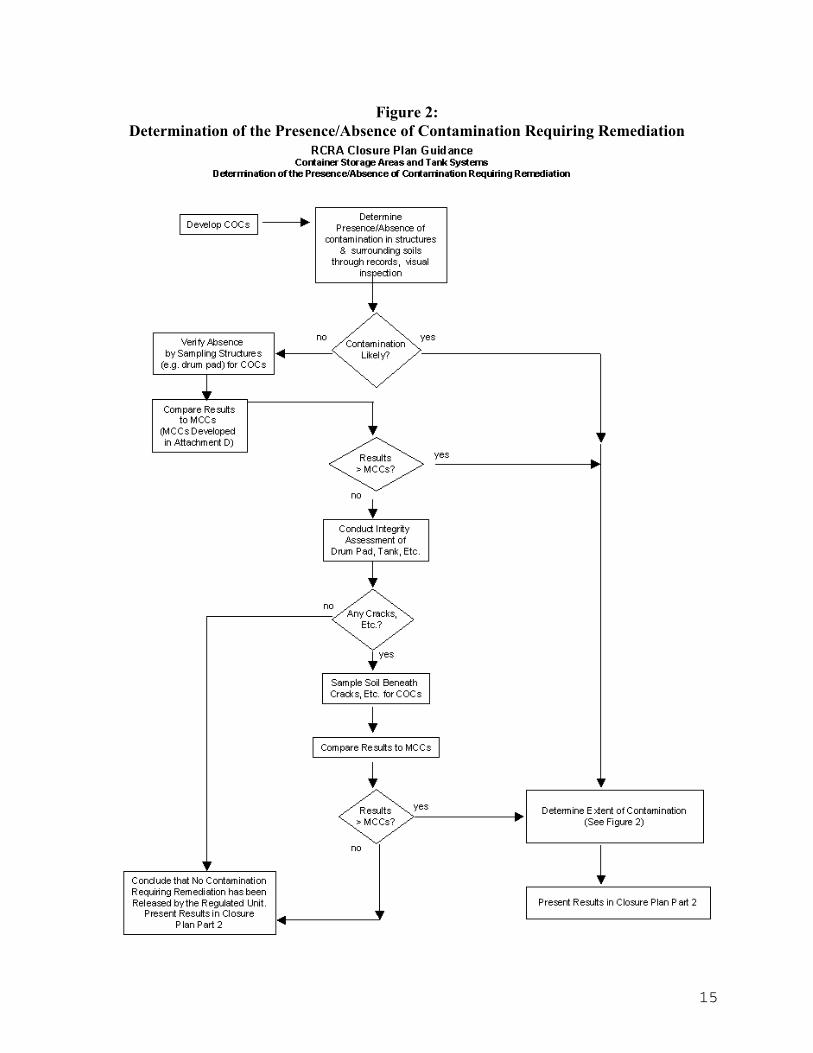
C. Identify the Presence/Absence of Contamination Requiring Remediation
The Site Characterization Work Plan must describe how the regulated unit structures and soils will be assessed to determine whether contamination has been released by the regulated unit and requires remediation. Figure 2 on the next page provides a visual explanation of what is described below.
If there is a record of a release, or there is physical or analytical evidence of a release of contaminants to structures or soils, then this step is not necessary; proceed to determination of the extent of contamination as described in the next section (IV). If there is no evidence of a release then verification sampling and analysis of structures and soils must be performed as follows:
1. Presence/Absence of Contamination on Structures
Determine whether the structures have been contaminated by the following:
a. Obtain a statistically representative number of samples of the structure, at randomly chosen locations, for analysis of the COCs.
b. The sampling method should not impact sample integrity, e.g. chip is favored over core sampling to avoid loss of volatiles.
c. Describe the sampling and analysis procedures. Indicator constituents can be used but the full COC list must be used if the indicator parameter results do not exceed media closure criteria (described below). Mass analysis can be used and leach values can be calculated if necessary.
d. For metals, compare each discrete sample result to the relevant media closure criteria and exposure pathway (media closure criteria are described in Attachment D). If any result exceeds the media closure criteria (MCC), then determine the extent of contamination as described in the next section. For volatiles, any detectable level triggers the need to measure the extent of contamination.
e. If the metals results are below MCCs and there are no detectable levels of volatiles then the structures can be considered free of contamination requiring remediation. Proceed to the determination of the presence/absence of contamination in soils, paragraph B below.
14
2. Presence/Absence of Contamination in Soils From Secondary Containment Structures
The work plan must describe how the structural integrity of secondary containment systems (e.g. container storage areas, tank systems) will be assessed for their potential impact to surrounding or underlying soils. Some considerations in this assessment are as follows:
a. Inspect pad and perimeter berms for features, e.g. expansion joints, cracks (including hairline), gaps, deteriorating concrete, which could have allowed a release of contaminants. Make sure that resurfacing/recoating of pad has not concealed cracks, etc.
b. Inspect for the above features after a dry sweep of the pad but prior to full decontamination,
c. If any of the above features are present, determine if contaminants migrated to the subsoils using the following procedure:
i. Bore a 4 inch core through the containment structure at the suspected conduit(s) and remove plug(s),
ii. Inspect each plug cross section,
iii. If feature (e.g. crack) extends through plug, sample each soil horizon down to groundwater, analyze (mass basis) each sample for the indicator COCs or full COC list if indicators are not detected.
iv. If any metal exceeds MCCs in any soil type or any volatile is detected then determine the extent of the contamination as described in the next section.
v. If crack does not extend through plug but volatile organics are on the constituent of concern list, use a portable organic vapor analyzer to measure soil vapors in the slab borehole.
(a) If volatile organics are detected in the borehole, determine extent of the volatile contamination as described in the next section.
(b) If volatile organics are not detected in the borehole, then further investigation for the extent of contamination in soil (described in the next section IV) is not necessary.
vi. Regrout boreholes before proceeding with closure.
15
Figure 2: Determination of the Presence/Absence of Contamination Requiring Remediation

16
3. Presence/Absence of Contamination in Soils from Tank Systems
The following is specific to tank systems when assessing their structural integrity for potential impact to surrounding or underlying soils.
A tank system integrity assessment can be conducted to prove that the tank system never leaked. If successful, subsoils need not be investigated for presence or extent of contamination. The completed integrity assessment must be appended to Closure Plan Part 2. If the tank is known to have leaked then the assessment is not necessary; proceed to determination of the extent of contamination.
The tank system integrity assessment includes:
a. A written assessment of the structural integrity of each tank system which is reviewed and certified by an independent, qualified, registered professional engineer.
b. For non-enterable, underground tank systems including ancillary components, the assessment should include a leak test. State-of-the-art leak test methodology must be used. Select a leak test after consulting with a qualified, independent, registered professional engineer.
c. All assessments must inspect each tank system component for cracks, leaks, corrosion, and erosion.
d. For tank systems which had secondary containment for their entire operating life, provide a summary of the leak inspections or leak-detection system monitoring data to verify that no leaks ever occurred during the lifetime of the tank system. If this information is not available, conduct an integrity assessment as described above.
e. If the tank integrity assessment indicates that there was a potential for leakage then determine the extent of the contamination as described in the next section.
f. In addition to the integrity assessment, the operating practices, e.g. filling/emptying, must be evaluated for potential sources of contaminant release.
D. Determine the Extent of Contamination in Structures and Soils
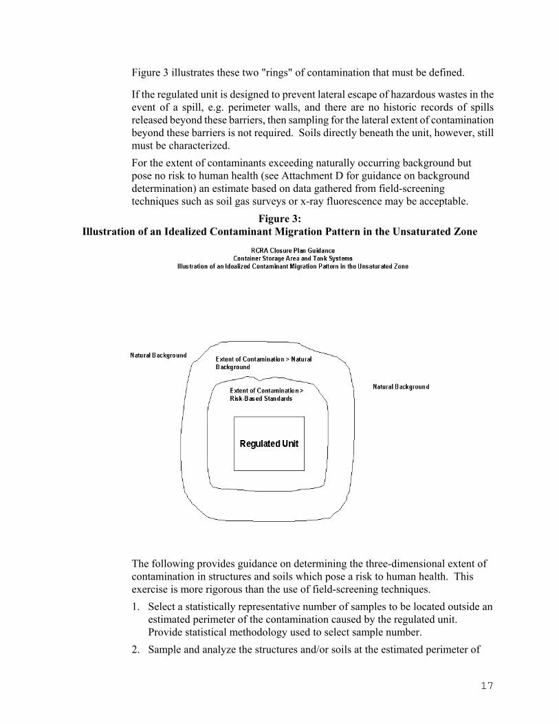
If contamination is found to be present in either the structures or soils of the regulated unit during the previously described exercise, the work plan must describe how the three-dimensional extent of contamination in both media will be determined. For unsaturated soils, you must determine the extent of contaminants which exceed naturally occurring background levels but, based on current toxicity information, pose no risk to human health. In addition, you must determine the extent of contaminants which pose a risk to human health and will need to be remediated.
17
Figure 3 illustrates these two "rings" of contamination that must be defined.
If the regulated unit is designed to prevent lateral escape of hazardous wastes in the event of a spill, e.g. perimeter walls, and there are no historic records of spills released beyond these barriers, then sampling for the lateral extent of contamination beyond these barriers is not required. Soils directly beneath the unit, however, still must be characterized. For the extent of contaminants exceeding naturally occurring background but pose no risk to human health (see Attachment D for guidance on background determination) an estimate based on data gathered from field-screening techniques such as soil gas surveys or x-ray fluorescence may be acceptable.
Figure 3: Illustration of an Idealized Contaminant Migration Pattern in the Unsaturated Zone
The following provides guidance on determining the three-dimensional extent of contamination in structures and soils which pose a risk to human health. This exercise is more rigorous than the use of field-screening techniques. 1. Select a statistically representative number of samples to be located outside an
estimated perimeter of the contamination caused by the regulated unit. Provide statistical methodology used to select sample number.
2. Sample and analyze the structures and/or soils at the estimated perimeter of
18
the contamination. Sampling and analysis procedures must be described.
3. Sample borings should extend to mean seasonal low groundwater, and samples should be taken at each soil horizon. Illustrate the sample depth, concentration data, each soil type, and the location of groundwater on a cross-sectional diagram.
4. General Sampling and Analysis Guidance for Determining the Extent of Contamination:
a. Use of indicator parameters is allowed but the full constituent-of-concern list must be analyzed at the sampling round thought to be at the extent of contamination.
b. Mass analysis is acceptable for the indicator parameters however all final samples must be analyzed for both mass and TCLP, or TCLP can be calculated by dividing the mass value by 20.
c. Obtain discrete samples; no compositing.
d. For sampling of organics in soil, take from 6 inches below the surface to avoid bias due to volatilization.
e. Perform all site characterization sampling prior to decontamination or removal of containment structures.
f. See Attachment C Tables 1-4 and 1-5 for further guidance on sampling and analysis.
5. Describe Decision Process to Conclude Sampling
The work plan must describe how to determine whether the extent of contamination has been defined and no further sampling is necessary. Consider the following:
a. Compare each discrete sample result with the Media Closure Criteria (MCC). MCCs are developed as described in Attachment D.
b. If any sample result is in excess of the MCCs then move outward and/or deeper and resample. The extent of contamination requiring remediation is defined by the outermost or deepest set of samples which contain constituents of concern at concentration levels at or below established MCCs. Structures and soils requiring remediation are those which lie within this sampling perimeter.
6. Present all analytical results in Closure Plan Part 2.
7. One of the purposes of conducting site characterization before completing the

19
closure plan is to determine if contamination is present which is unrelated to the activities of the regulated unit. If this occurs, DEP will evaluate these situations on a case-by-case basis. Some of the issues that will need to be addressed:
a. Where does RCRA interim-status closure leave off and where does Corrective Action take over in cleaning up the non-RCRA contamination?
b. Will the remediation standards be any different between the two programs?
c. When will Corrective Action be implemented at the site?

20
CLOSURE PLAN PART 2: RESULTS OF SITE CHARACTERIZATION PROGRAM
AND PROPOSED CLOSURE APPROACH Once the Site Characterization Work Plan has been implemented the results should be presented in Closure Plan Part 2. Using these results, a proposal should be made in Closure Plan Part 2 to close the regulated unit "clean" or close it as a landfill*. The following provides guidance on each of these objectives.
I. Site Characterization Sampling and Analysis Results
A. Include all site characterization sampling and analytical results including summary tables, laboratory reports and chain-of-custody documentation.
B. Although not required in this report, laboratory QA/QC data and chromatograms must be made available to DEP upon request.
C. Include the Media Closure Criteria and flag those results which exceed the criteria.
D. Analytical detection levels must be provided for all results presented.
E. Data Presentation
All media closure criteria and analysis data must be expressed in units which are clearly defined, labeled and used consistently throughout the closure plan and any appended laboratory reports. The following units must be used:
1. Inorganics:
a. Mass analysis of soil - milligrams per kilogram (Mg/kg)
b. Analysis of soil leachate - milligrams per liter (Mg/l)
c. Air - milligrams per cubic meter (Mg/m3)
2. Organics:
a. Mass analysis of soil - micrograms per kilogram (ug/kg)
b. Analysis of soil leachate - micrograms per liter (ug/l)
c. Air - micrograms per cubic meter (ug/m3)
F. Illustrate the 3-dimensional contaminant profile in soil with contour maps and cross-sectional diagrams. Include the location of the regulated unit, soil horizons, and depth to groundwater.

21
II. Proposed Closure Approach
A. Clean closure generally should be proposed if:
1. Surrounding and underlying soil has not been impacted by releases from the regulated unit or
2. Surrounding and underlying soil (which has been impacted) can be removed or decontaminated within the 180-day closure period.
B. Landfill Closure* generally should be proposed if:
1. The underlying or surrounding soil has been impacted by the regulated unit and the facility has decided that removal and/or decontamination of the soil is not feasible. Once the Connecticut Clean-up Standard Regulations become promulgated they will define and limit those circumstances under which contamination may be left in place.
2. If soil is contaminated down to the seasonal low ground water elevation then it is likely that groundwater has been impacted. For these sites, DEP will determine the most appropriate closure approach on a case-by-case basis.
III. Departures From Site Characterization Work Plan
Describe and justify those portions of the completed site characterization program that departed from the accepted site characterization work plan.
*Note: As stated in 40 CFR Part 265.197(b) regarding closure of tank systems: "If the owner or operator demonstrates that not all contaminated soils can be practicably removed or decontaminated......then the o/o must close the tank system and perform post-closure care in accordance with the closure and post-closure care requirements that apply to landfills (265.310)." Even though the regulations regarding closure of drum storage areas do not use this language, DEP will require that drum storage areas in similar situations be subject to closure as a landfill.

22
CLOSURE PLAN PART 3: REMEDIATION, VERIFICATION, QA/QC, CERTIFICATION
Closure Plan Part 3 describes the steps to remove and dispose of the hazardous waste, and the steps to remove and/or decontaminate media identified in the site characterization phase of the process as being contaminated.
Part 3 is the final document that will be submitted. We recommend that it be submitted so that it can be easily combined with Closure Plan Parts 1 and 2 to form the complete closure plan.
The following Sections I and II provide general guidance on writing both container storage and tank closure plans. Section III provides specific guidance for tank systems.
I. Closure Performance Standard
A. The closure performance standard specified in 40 CFR 265.111 is a regulation stating the general objectives of closure. This must not be confused with the media closure criteria or risk-based standards.
B. This requirement is satisfied by stating in the closure plan that closure will be carried out as required by this regulation, i.e. quote the regulation.
II. Removal and disposal/decontamination of waste, equipment, structures and soil
The closure plan must describe how the following activities will be performed:
A. Remove and dispose of all hazardous waste inventory from the regulated unit. Provide the name and location of the licensed hazardous waste facility that will receive the waste.
B. Decontaminate or remove and dispose of all equipment, structures and soils measured to be in excess of the media closure criteria. The following must be specified in the closure plan:
1. Method of decontamination and/or removal,
2. Means for collection and disposal of decontamination or removal residues,
3. Type of decontamination solutions to be used,
4. Method used to prevent the release of hazardous constituents to surrounding or underlying structures, soils, room air, or ambient air during decontamination and/or removal. As an example, if cracks or gaps were discovered during the site characterization phase of closure then they must be sealed prior to any decontamination procedures to prevent the release of residues to the subsoils,
5. An estimate of the volume of the decontamination and/or removal residues to be generated,
23
6. Name and location of proposed off-site facility which will receive decontamination and/or removal residues,
7. Method used to perform a hazardous waste determination on the decontamination and/or removal residues, (See Attachment C - Table 1-6),
8. Method to be used to decontaminate all equipment used in the decontamination and/or removal process,
9. Use manifest if decontamination and/or removal residues are hazardous waste, restricted from land disposal, or are Connecticut Regulated Wastes,
10. Obtain permission from DEP to dispose of decontamination and/or removal residues if they are non-hazardous waste and are to be disposed of at an in-state solid waste landfill,
11. Provide the location of the staging area for the decontamination and/or removal residues,
12. State that worker health and safety will be addressed in accordance with 29 CFR 1910.120. A complete health and safety plan is not necessary and CTDEP does not have the authority to approve them.
C. Include the following sampling and analysis methods that will be used to confirm that decontamination and/or removal achieved stated media closure criteria, (also see Attachment C - Tables 1-7 and 1-8):
1. Statistically representative number of samples at a 95 percent level of confidence. See the following references for the statistical procedures for selecting sample size:
• Technical Guidance Document: Construction Quality Assurance for Hazardous Waste Land Disposal Facilities, dated October, 1986, EPA/530-SW-86-031
• Test Methods for Evaluating Solid Waste, SW-846
2. Sample locations chosen randomly and judgmentally,
3. Sample floor, walls and ceilings of storage area if these structures were decontaminated,
4. Obtain chip samples if porous media, wipe sample if non-porous media,
5. See wipe sampling procedure in Attachment A,
6. Clean-up criteria for wipe samples is non-detect for all COCs; in cases where interferences are encountered, e.g. metals detected from a steel tank, an alternative to the "non-detect" criteria may be proposed,

24
7. No compositing of samples; analyze all discrete samples individually,
8. Media closure criteria must be achieved for each COC at each sample point; comparison of a mean concentration to clean-up criteria is not acceptable. Remove or decontaminate again if media closure criteria is not achieved,
9. If subsoils are removed, describe how the floor and sidewalls of the excavation will be sampled and analyzed.
D. Backfilling of excavations
1. Clean soil must be used; provide analysis results of representative samples of clean soil, and provide location and history of borrow site.
2. Backfilled soil must be compacted when placed in the excavation in such a manner as to prevent post-closure settlement.
III. Removal and Decontamination of Tank Systems
The following guidance is specific to tank systems. For more information read 40 CFR 265 Subpart J:
A. As stated earlier, a "tank system" includes:
1. Tank,
2. Secondary containment structure,
3. All ancillary equipment directly connected to the tank or secondary containment structure, e.g. piping, pressure relief valves, instrumentation, valves, level sensors.
B. Remove all hazardous wastes and residues from the tank system.
C. Verify that decontamination of the tank system was successful using the same methods described for container storage areas. In most cases, the tank itself will be non-porous and will require a wipe test described previously. For tank system piping, triple rinse with an appropriate decontamination solution and analyze the final rinse for all constituents of concern to verify that all media closure criteria have been met. Also see Attachment C - Tables 1-8 and 1-9.
D. Final disposition of tank system components can be accomplished by either:
1. Removing and disposing of tank if required by the State Fire Marshall, or
2. Abandoning in-place provided the tank is filled with an inert dry sand or equivalent media.
E. If tank is to remain in service after completion of closure, specify the material to be stored.

25
F. Remove or decontaminate contaminated soil in a manner similar to that described previously for container storage areas.
G. For additional information on closing tank systems, see Chapter 12 of the Technical Resource Document For The Storage And Treatment Of Hazardous Waste In Tank Systems, dated December 1986, NTIS #PB87-134391.
IV. Quality Assurance and Quality Control Procedures (QA/QC)
Describe the procedures to be used to ensure that the closure will be completed in accordance with the approved closure plan
A. Must be consistent with all applicable sections of: Technical Guidance Document: Construction Quality Assurance For Hazardous Waste Land Disposal Facilities , dated October 1986, EPA/530-SW-86-031.
B. Identify the responsibility and authority of each individual or organization listed below who is involved with QA/QC:
1. Engineer,
2. QA/QC personnel,
3. Construction contractor.
C. Describe the project meetings that will take place, including pre-closure meetings, and meetings to discuss deviations from the approved closure plan.
D. Provide the qualifications of the QA/QC coordinator, the QA/QC inspectors, and the engineering consultant.
E. Describe the QA/QC for sampling and chain-of-custody procedures.
F. Specify that all laboratory analyses will be conducted using QA/QC procedures specified in the EPA document Test Methods for Evaluation Solid Waste, SW-846.
V. Closure Schedule
A. Provide a schedule of closure.
B. State that closure activities will be completed within 180 days of approval of the closure plan.
C. Are any extensions to the time limits anticipated? If so provide justification.
D. Will seasonal conditions impact schedule?
VI. Financial Assurance/Closure Cost Estimates
A. Provide an estimate of the closure costs in accordance with 22a-449(c)-105 of the
26
CTHWMR and 40 CFR 265.142.
B. Provide documentation that financial assurance for closure has been obtained sufficient to cover the cost of closure. This must be in accordance with 22a-449(c)-105 of the CTHWMR and 40 CFR 265.143.
VII. Certification of Closure
The closure plan must state that a closure certification report will be prepared after closure is complete and that the following will be included in the report:
A. Provision for certification by owner or operator within 60 days following closure,
B. Provision for certification by independent registered Professional Engineer that facility was closed in accordance with the approved closure plan,
C. Provision for Closure Documentation Report to document closure activities,
D. Summary of all QA/QC data collected during closure,
E. Photographic record of each milestone event, (identify each event in the plan),
F. List and justify all departures from approved closure plan,
G. Certification statement,
H. Verification sample results after decontamination or removal of equipment, structures and soil,
I. If clean closure was achieved but there are other operating units at the facility, submit a revised Part A permit application by deleting the closed regulated unit,
J. For a complete closure, i.e. all regulated units closed, the Part A must be withdrawn; the withdrawal request must be submitted with the closure certification document.
VIII. Appendices
A. Do not append previous revisions of the closure plan to the closure plan.
B. Provide separating pages with tabs to divide each appendix.
C. Submit legible copies.
Last Updated: June, 2005
27
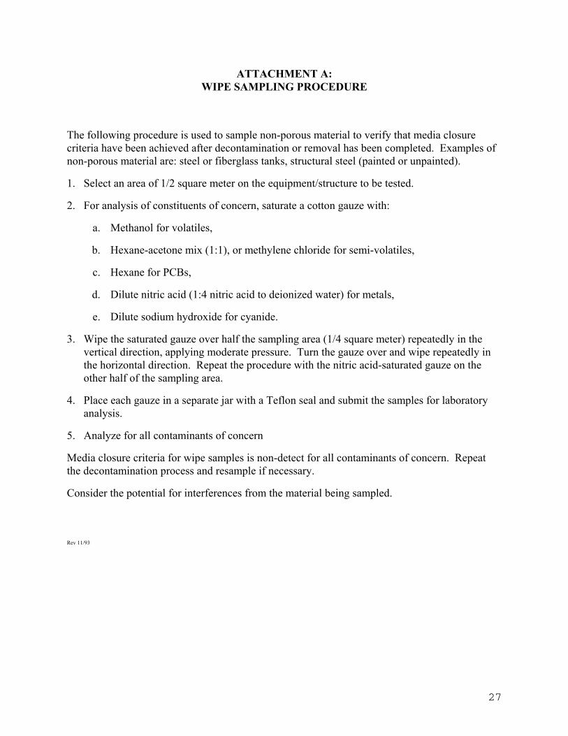
ATTACHMENT A: WIPE SAMPLING PROCEDURE
The following procedure is used to sample non-porous material to verify that media closure criteria have been achieved after decontamination or removal has been completed. Examples of non-porous material are: steel or fiberglass tanks, structural steel (painted or unpainted).
1. Select an area of 1/2 square meter on the equipment/structure to be tested.
2. For analysis of constituents of concern, saturate a cotton gauze with:
a. Methanol for volatiles,
b. Hexane-acetone mix (1:1), or methylene chloride for semi-volatiles,
c. Hexane for PCBs,
d. Dilute nitric acid (1:4 nitric acid to deionized water) for metals,
e. Dilute sodium hydroxide for cyanide.
3. Wipe the saturated gauze over half the sampling area (1/4 square meter) repeatedly in the vertical direction, applying moderate pressure. Turn the gauze over and wipe repeatedly in the horizontal direction. Repeat the procedure with the nitric acid-saturated gauze on the other half of the sampling area.
4. Place each gauze in a separate jar with a Teflon seal and submit the samples for laboratory analysis.
5. Analyze for all contaminants of concern
Media closure criteria for wipe samples is non-detect for all contaminants of concern. Repeat the decontamination process and resample if necessary.
Consider the potential for interferences from the material being sampled.
Rev 11/93

28
ATTACHMENT B: CALCULATION OF WORST-CASE AIR CONCENTRATIONS
To verify that the Media Closure Criteria for the air inhalation pathway have been achieved after remediation.
1. Measure the total mass of the concrete slab:
Slab Volume * density of concrete
Cubic Meters * Kilograms/Cubic meters = kg
2. Measure room dimensions and calculate volume of air in the storage area in cubic meters
3. Analyze a representative number of samples of concrete for each COC, on a mass basis (mg/kg).
4. Calculate the room air concentration for each COC, for each sample point, assuming the total constituent mass is released to the room air at one instant, and remains there for a 70-year exposure period:
Cc * Mc CRA =
VRA
Where: CRA = Concentration of room air for a given constituent (mg/m3) Cc = Mass Concentration of a given constituent in the concrete (mg/kg) Mc = Mass of concrete slab (kg) VRA = Volume of room air (m3)
5. Compare CRA to the media closure criteria for each COC.

29
ATTACHMENT C: SAMPLING AND ANALYSIS GUIDANCE
TABLE 1-1: Analysis of Waste for Appendix IX Parameters
Number of Samples: 1 per waste type, or 1 composite of all waste
types if compatible and there are no analytical interferences.
Selection of Sample Locations: Waste containers or tanks
Sampling Methodology Composite: Yes, if compatible Discrete: Yes, if incompatible Chip (Porous media): N/A Wipe (Non-Porous media): N/A
Analysis Parameters Target Parameters: N/A Complete COC List: N/A
Analysis of: Total Constituent Mass: Yes Extract from Leach Procedure: No
VOC screening (Portable organic vapor analyzer): N/A
NOTE: Analysis of waste for Appendix IX parameters is only necessary if waste analysis data is
not available.

30
TABLE 1-2: Analysis of Secondary Containment Structures for Appendix IX Constituents
Number of Samples: Inorganics: 1 per 100 square feet of surface area, but no less
than 3 total Organics: 1 per regulated unit
Selection of Sample Locations: Inorganics: Random and judgmental Organics: Use portable organic vapor analyzer to locate
most elevated levels for sample
Sampling Methodology: Composite: Yes, for inorganics only Discrete: Yes, for organics only Chip (Porous media): Yes Wipe (Non-Porous media): Yes
Analysis Parameters: Target Parameters: N/A Complete COC List: N/A
Analysis of: Total Constituent Mass: Yes Extract from Leach Procedure: No
VOC screening (Portable organic vapor analyzer): Yes, for organics

31
TABLE 1-3: Development of Background Values for Media Closure Criteria
Number of Samples: Statistically representative number
Selection of Sample Locations: In an area believed to be unaffected by the
activities of the regulated unit
Sampling Methodology: Composite: No Discrete: Yes Chip (Porous media): Yes Wipe (Non-Porous media): N/A
Analysis Parameters: Target Parameters: Yes, only those for which a media closure
criteria is needed, but exclude all volatile organics
Complete COC List: No
Analysis of : Total Constituent Mass: Yes, if needed Extract from Leach Procedure: If needed
VOC screening: (Portable organic vapor analyzer): N/A

32
TABLE 1-4: Site Characterization - Determination of Lateral Extent of Contamination
Number of Samples: Arbitrary but must be demonstrated to be
statistically representative using SW-846 Volume II Chapter 9
Selection of Sample Locations: At or beyond estimated lateral extent of contamination. Move outward if contaminants found
Sampling Methodology: Composite: No Discrete: Yes Chip (Porous media): Yes if structure, N/A if soil Wipe (Non-Porous media): N/A
Analysis Parameters: Target Parameters: Yes Complete COC List: Yes, at outermost sample point Analysis of : Total Constituent Mass: Yes Extract from Leach Procedure: Yes or can calculate (Mass/20) VOC screening: (Portable organic vapor analyzer): Contractor's discretion NOTE: Not necessary to sample beyond berms or walls if: 1) There is no record of spills outside containment area and 2) berms and walls have no cracks, gaps or deterioration

33
TABLE 1-5: Site Characterization - Determination of Vertical Extent of Contamination
Number of Samples: 1 per potential contaminant conduit (e.g. crack,
gap) per each soil horizon until extent of contamination is reached
Selection of Sample Locations: At potential contaminant conduits
Sampling Methodology: Composite: No Discrete: Yes Chip (Porous media): N/A Wipe (Non-Porous media): N/A
Analysis Parameters: Target Parameters: Yes Complete COC List: At deepest sample Analysis of : Total Constituent Mass: Yes Extract from Leach Procedure: Yes or can calculate (Mass/20)
VOC screening: (Portable organic vapor analyzer): Yes, sample for vapor in bore hole in cases
where conduit does not extend through plug removed from concrete slab. This verifies that organics never migrated through the porous concrete

34
TABLE 1-6: Hazardous Waste Determination - Equipment, Structures, Soils Disposed of Offsite
Number of Samples: 1 per 20 cubic yards
Selection of Sample Locations: Random and judgmental
Sampling Methodology: Composite: No Discrete: Yes Chip (Porous media): Yes Wipe (Non-Porous media): N/A
Analysis Parameters: Target Parameters: Yes Complete COC List: As needed
Analysis of : Total Constituent Mass: No Extract from Leach Procedure: Yes
VOC screening: (Portable organic vapor analyzer): N/A

TABLE 1-7: Post-Decontamination Sampling of Soils
Number of Samples: Arbitrary; must be demonstrated to be statically
representative using SW-846 Volume II, Chapter 9
Selection of Sample Locations: Random and judgmental
Sampling Methodology: Composite: No Discrete: Yes Chip (Porous media): N/A Wipe (Non-Porous media): N/A
Analysis Parameters: Target Parameters: Screening only Complete COC List: Yes
Analysis of : Total Constituent Mass: Yes Extract from Leach Procedure: Yes, or calculate (Mass/20)
VOC screening: (Portable organic vapor analyzer): Contractor discretion

TABLE 1-8: Post-Decontamination Sampling of Tanks and Secondary Containment Structures which
are Constructed of Porous Material Number of Samples: Arbitrary but must be demonstrated to be
statistically representative using SW-846 Volume II Chapter 9
Selection of Sample Locations: Random and judgmental
Sampling Methodology: Composite: No Discrete: Yes Chip (Porous media): Yes Wipe (Non-Porous media): N/A
Analysis Parameters: Target Parameters: Only for screening Complete COC List: Yes
Analysis of : Total Constituent Mass: Yes Extract from Leach Procedure: Yes or calculate (Mass/20)
VOC screening: (Portable organic vapor analyzer): Contractor discretion

TABLE 1-9: Post-Decontamination Sampling of Tanks and Secondary Containment Structures which
are Constructed of Non-porous Material Number of Samples: 1/2 square meter per regulated unit
Selection of Sample Locations: Judgmental
Sampling Methodology: Composite: N/A Discrete: N/A Chip (Porous media): N/A Wipe (Non-Porous media): Yes
Analysis Parameters: Target Parameters: No Complete COC List: Yes
Analysis of : Total Constituent Mass: Yes Extract from Leach Procedure: No
VOC screening: (Portable organic vapor analyzer): Contractor Discretion Notes:
1. Closure criteria for wipe sampling is the lowest analytical detection level for all COC's
2. See Attachment A for Wipe Sampling Procedure

ATTACHMENT D: GUIDANCE ON DEVELOPING MEDIA CLOSURE CRITERIA
Media closure criteria (MCCs) are contaminant concentrations in environmental media that will pose no risk to human health and the environment. MCCs are used to define the extent of contamination that must be remediated, and they are used to verify that the remediation was successful. An MCC must be developed for each constituent of concern (COC) and each applicable media, (soil, soil water, i.e. water leached from soil, concrete, air), as defined by the human exposure pathways at a given site. Using this procedure usually results in two or three MCCs developed for each COC to address each exposure pathway.
The numeric criteria found in the Remediation Standard Regulations (RSRs), adopted by the Commissioner pursuant to RCSA Sections 22a-133k and 22a-133q, are the source of media closure criteria for closure. All media closure criteria must be developed consistent with the RSRs. Go to http://www.dep.state.ct.us/wtr/regs/remediationregs.htm to access the RSRs on the web.
Please use the soil criteria in the RSRs as the media closure criteria for concrete.
I. Guidance on Developing MCCs Based on Background Samples
Refer to the RSRs for determining media closure criteria based on background concentrations in soil for naturally-occurring substances.
II. Expression of media closure criteria and related analytical data units
All media closure criteria and related analytical data must be expressed in units which are clearly defined, labeled and used consistently throughout the closure plan and any appended laboratory reports. The following units must be used:
A. Inorganics:
1. Mass analysis of soil - milligrams per kilogram (mg/Kg)
2. Analysis of soil leachate - milligrams per liter (mg/l)
3. Air - milligrams per cubic meter (mg/m3)
B. Organics:
1. Mass analysis of soil - milligrams per kilogram (mg/Kg)
2. Analysis of soil leachate - micrograms per liter (µg /l)
3. Air - micrograms per cubic meter (µg /m3)