rcp4cr catalogue extract robocylinder rcp4cr-sa5c
TRANSCRIPT

RCP4CR RoboCylinder
P29 RCP4CR-SA5CExtract RCP4 RoboCylinder Cat V2No 1012-E Version CJ0182-4B
GBCatalogue Extract RCP4 Cleanroom Type with Pulse Motor
Code explanation ➀ Stroke ➁ Cable length ➂ Options (unit mms)The values in lt gt apply when the actuator is used vertically
Leads and Payloads
Model number Lead (mm)
Maximum payload Stroke(mm)Horizontal (kg) Vertical (kg)
RCP4CR-SA5C-I-42P-20- ➀ -P3- ➁ - ➂ 20 65 1
50~800(every 50mm)
RCP4CR-SA5C-I-42P-12- ➀ -P3- ➁ - ➂ 12 9 25
RCP4CR-SA5C-I-42P-6- ➀ -P3- ➁ - ➂ 6 18 6
RCP4CR-SA5C-I-42P-3- ➀ -P3- ➁ - ➂ 3 20 12
9
0
565
255
1
66
910
151820
25
0
2
4
6
8
10
12
14
Lead 3
Lead 6
Lead 6
Lead 12 Lead 20 (when operated at 03G)
The values for leads 3612 are based on PCON-CA operation at 03G
The values for leads 3612 are based on PCON-CA operation at 03G
16001400120010008006004002000
1400120010008006004002000
Lead 3
Lead 20 (when operated at 05G)Lead 12
Horizontal
Vertical
Speed (mms)
Speed (mms)
Payl
oad
(kg)
Payl
oad
(kg)
05 05
Lead 20 (when operated at 05 G)
1
Stroke and Maximum Speed50~450(50mm)
500(mm)
550(mm)
600(mm)
650(mm)
700(mm)
750(mm)
800(mm)
20 1440lt1280gt
1440lt1280gt 1225 1045 900 785 690 610
12 900 795 665 570 490 425 375 330
6 450 395 335 285 245 215 185 165
3 225 195 165 140 120 105 90 80
Stroke
Lead
RCP4CR-SA5C Cleanroom RoboCylinder Slider Type Motor Unit CoupledActuator Width 52mm 24-V Pulse Motor
42P Pulse motor size 42
I Incremental P3 PCON-CA MSEP-C
N None P 1m S 3m M 5mXR Robot cable
Refer to the options table below
20 20mm 12 12mm 6 6mm 3 3mm
Lead Stroke Cable length OptionsTypeSA5C
Encoder typeI
Motor type42P
Applicable controllerP3
SeriesRCP4CRModel
SpecicItems
50 50mm
800 800mm(every 50mm)
Correlation Diagrams of Speed and Payload With the RCP4 series due to the characteristics of the pulse motor payload decreases as the speed increases Use the chart below to conrm that the desired speed and payload requirements are met
(1) The payload is the value when operated at 03 G acceleration The upper limit of acceleration is 1 G (or 05 G in a vertical
installation) Note that raising the acceleration causes the payload to drop 02 G for the 20mm-lead model
Type Cable symbol
Standard typeP (1m)S (3m)M (5m)
Special lengthX06 (6m) ~ X10 (10m)X11 (11m) ~ X15 (15m)X16 (16m) ~ X20 (20m)
Robot cable
R01 (1m) ~ R03 (3m)R04 (4m) ~ R05 (5m)R06 (6m) ~ R10 (10m)R11 (11m) ~ R15 (15m)R16 (16m) ~ R20 (20m)
Cable Length
Actuator Specications (based on operation with PCON-CA controller)
Actuator SpecicationsItem Description
Drive system Ball screw 10mm rolled C10
Cleanliness ISO class 4 (US FED STD class 10)Ambient operating temperature humidity
Options
Lost motion 01mm or lessPositioning repeatability (1) plusmn002mm [plusmn003mm]
Dynamic allowable moment (2) Ma 49 Nm Mb 68 Nm Mc 117 NmAllowable overhang 150mm or less in Ma Mb and Mc directions
L
L
Ma MaMb Mc Mc
Allowable load moment directions Overhang load lengths
(1) The values enclosed in [ ] apply for 20mm lead(2) Based on 5000km of traveling life
Suction volume(Nlmin)
80
50
30
15
B 8 CJT 8CJR 8CJL 8CJB 8NM 8
VR 8
Name Option code See pageBrakeCable exit direction (Top)Cable exit direction (Right)Cable exit direction (Left)Cable exit direction (Bottom)Non-motor end specicationIntake port (vacuum joint) onopposite side
RCP4 RoboCylinder
RCP4CR-SA5C P30Extract RCP4 RoboCylinder Cat V2No 1012-E Version CJ0182-4B
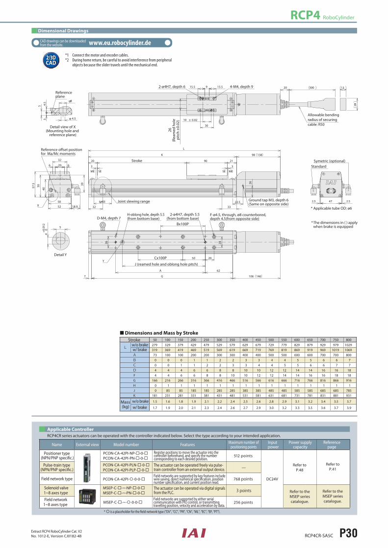
Dimensional Drawings
2D CAD23D CAD
CAD drawings can be downloaded from the website wwweurobocylinderde
1 Connect the motor and encoder cables2 During home return be careful to avoid interference from peripheral objects because the slider travels until the mechanical end
512 points
DC24V
Refer toP48
Refer to theMSEP seriescatalogue
Refer to theMSEP seriescatalogue
Refer toP41mdash
768 points
3 points
256 points
is a placeholder for the eld network type (ldquoDVldquo ldquoCCldquo ldquoPRldquo ldquoCNldquo ldquoMLldquo ldquoECldquo ldquoEP ldquoPTldquo)
RCP4CR series actuators can be operated with the controller indicated below Select the type according to your intended applicationApplicable Controller
Positioner type(NPNPNP specic)
Pulse-train type
Field network type
Field network1~8 axes type
Solenoid valve1~8 axes type
(NPNPNP specic)
PCON-CA-42PI-NP--0-PCON-CA-42PI-PN--0-
PCON-CA-42PI-PLN--0-PCON-CA-42PI-PLP--0-
MSEP-C--~-NP--0-MSEP-C--~-PN--0-
MSEP-C--~--0-0-
PCON-CA-42PI--0-0-
Register positions to move the actuator into thecontroller beforehand and specify the numbercorresponding to each desired position
Field networks are supported by key features includewire-saving direct numerical specication positionnumber specication and current position read
Field networks are supported by either serialcommunication with PIO control or transmittingtravelling position velocity and acceleration by data
The actuator can be operated freely via pulse-train controller from an external output device
The actuator can be operated via digital signalsfrom the PLC
50 100 150 200 250 300 350 400 450 500 550 600 650 700 750 800
L279 329 379 429 479 529 579 629 679 729 779 829 879 929 979 1029319 369 419 469 519 569 619 669 719 769 819 869 919 969 1019 1069
A 73 100 100 200 200 300 300 400 400 500 500 600 600 700 700 800B 0 0 0 1 1 2 2 3 3 4 4 5 5 6 6 7C 0 0 1 1 2 2 3 3 4 4 5 5 6 6 7 7D 4 4 4 6 6 8 8 10 10 12 12 14 14 16 16 18F 4 4 6 6 8 8 10 10 12 12 14 14 16 16 18 18G 166 216 266 316 366 416 466 516 566 616 666 716 766 816 866 916H 0 1 1 1 1 1 1 1 1 1 1 1 1 1 1 1J 0 85 85 185 185 285 285 385 385 485 485 585 585 685 685 785K 181 231 281 331 381 431 481 531 581 631 681 731 781 831 881 931
15 16 18 19 21 22 24 25 26 28 29 31 32 34 35 37
17 19 20 21 23 24 26 27 29 30 32 33 35 36 37 39
Y
X(φ40)
3
Stroke
Joint slewing range
3
20
98(138)K
L
225
26
90 21
3332
ME MESE SE
13
28
9 155155
19 plusmn 002
30
20 300
62
2050
A
G 106(146)7
26 24
47 2525
39
50
52
40
575
50
20 66
32
189
5
φ 45
φ8
34
5
5
40
+00
12
Name External view Model number Features Maximum number of positioning points
Input power
Power supply capacity
Reference page
Refefor MaMc moments
Detail view of X(Mounting hole and
reference plane)
Referenceplane
Detail Y
The dimensions in ( ) apply when brake is equipped
Cx100P
Bx100P
F-oslash45 through oslash8 counterboreddepth 45(from opposite side)
2-oslash4H7 depth 55(from bottom base)D-M4 depth 7
H-oblong hole depth 55(from bottom base)
J (reamed hole and oblong hole pitch)
Allowable bendingradius of securingcable R50
StandardSymetric (optional)
Applicable tube OD oslash6
Ground tap M3 depth 6 (Same on opposite side)
26(R
eam
ed h
ole
pitc
h plusmn0
02)
4-M4 depth 92-oslash4H7 depth 6
Dimensions and Mass by StrokeStroke
Mass(kg)
wo brakew brake
wo brakew brake
RCP4CR RoboCylinder
P31 RCP4CR-SA6CExtract RCP4 RoboCylinder Cat V2No 1012-E Version CJ0182-4B
0
5
10
15
20
30
25
0
2
4
6
8
10
12
14
16001400120010008006004002000
1400120010008006004002000
Lead 3
Lead 6
Lead 3
65
1
Lead 12
Speed (mms)
Speed (mms)
Payl
oad
(kg)
Payl
oad
(kg)
Lead 6
Lead 12
18
12
05
525
105
9
Horizontal
The values for leads 3612 are based on operation at 03 G
The values for leads 3612 are based on PCON-CA operation at 03 G
The values for leads 3612 are based on operation at 03 G
The values for leads 3612 are based on PCON-CA operation at 03 G
Lead 20 (when operated at 05 G)
Lead 20 (when operated at 03 G)
Lead 20 (when operated at 03 G)
Lead 20 (when operated at 05 G)
Lead 20 (when operated at 05 G)
Vertical
Leads and Payloads Stroke and Maximum Speed
L
L
Ma MaMb Mc Mc
Allowable load moment directions Overhang load lengths
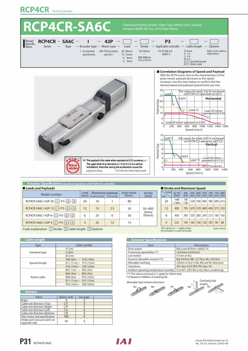
RCP4CR-SA6C Cleanroom RoboCylinder Slider Type Motor Unit CoupledActuator Width 58 mm 24-V Pulse Motor
42P Pulse motor size 42
I Incremental P3 PCON-CA MSEP-C
N None P 1 m S 3 m M 5 mXR Robot cable
Refer to the options table below
20 20mm 12 12mm 6 6mm 3 3mm
Lead Stroke Cable length OptionsTypeSA6C
Encoder typeI
Motor type42P
Applicable controllerP3
SeriesRCP4CRModel
SpecicItems
50 50mm
800 800mm(every 50mm)
(unit mms)Code explanation ➀ Stroke ➁ Cable length ➂ Options
Actuator Specications
Item DescriptionDrive system Ball screw 10mm rolled C10
Lost motion 01mm or lessPositioning repeatability (1) plusmn002mm [plusmn003mm]
Dynamic allowable moment (2) Ma 89 Nm Mb 127 Nm Mc 186 NmAllowable overhang 220mm or less in Ma Mb and Mc directions
Ambient operating temperature humidity 0 to 40degC 85 RH or less (Non-condensing)(1) The values enclosed in [ ] apply for 20mm lead(2) Based on 5000km of traveling life
(1) The payload is the value when operated at 03 G acceleration The upper limit of acceleration is 1 G (or 05 G in a vertical
installation) Note that raising the acceleration causes the
Correlation Diagrams of Speed and Payload With the RCP4 series due to the characteristics of the pulse motor payload decreases as the speed increases Use the chart below to conrm that the desired speed and payload requirements are met
The values in lt gt apply when the actuator is used vertically
Model number Lead (mm)
Maximum payload Suction volume(Nlmin)
Stroke(mm)Horizontal (kg) Vertical (kg)
RCP4CR-SA6C-I-42P-20- ➀ -P3- ➁ - ➂ 20 10 1 80
50 50~800(every 50mm)
RCP4CR-SA6C-I-42P-12- ➀ -P3- ➁ - ➂ 12 15 25
30
15
RCP4CR-SA6C-I-42P-6- ➀ -P3- ➁ - ➂ 6 25 6
RCP4CR-SA6C-I-42P-3- ➀ -P3- ➁ - ➂ 3 25 12
50~450(50mm)
500(mm)
550(mm)
600(mm)
650(mm)
700(mm)
750(mm)
800(mm)
20 1440lt1280gt
1440lt1280gt 1230 1045 905 785 690 615
12 900 795 670 570 490 430 375 335
6 450 395 335 285 245 215 185 165
3 225 195 165 140 120 105 90 80
Stroke
Lead
Type Cable symbol
Standard typeP (1m)S (3m)M (5m)
Special lengthX06 (6m) ~ X10 (10m)X11 (11m) ~ X15 (15m)X16 (16m) ~ X20 (20m)
Robot cable
R01 (1m) ~ R03 (3m)R04 (4m) ~ R05 (5m)R06 (6m) ~ R10 (10m)R11 (11m) ~ R15 (15m)R16 (16m) ~ R20 (20m)
Cable Length
Options
Cleanliness ISO class 4 (US FED STD class 10)
payload to drop 02 G for the 20mm-lead model
Actuator Specications (based on operation with PCON-CA controller)
B 8 CJT 8CJR 8CJL 8CJB 8NM 8
VR 8
Name Option code See pageBrakeCable exit direction (Top)Cable exit direction (Right)Cable exit direction (Left)Cable exit direction (Bottom)Non-motor end specicationIntake port (vacuum joint) onopposite side
RCP4 RoboCylinder
RCP4CR-SA6C P32Extract RCP4 RoboCylinder Cat V2No 1012-E Version CJ0182-4B
Dimensional Drawings
2D CAD23D CAD
CAD drawings can be downloaded from the website wwweurobocylinderde
1 Connect the motor and encoder cables2 During home return be careful to avoid interference from peripheral objects because the slider travels until the mechanical end
512 points
DC24V
Refer toP48
Refer to theMSEP seriescatalogue
Refer to theMSEP seriescatalogue
Refer toP41mdash
768 points
3 points
256 points
is a placeholder for the eld network type (ldquoDVldquo ldquoCCldquo ldquoPRldquo ldquoCNldquo ldquoMLldquo ldquoECldquo ldquoEP ldquoPTldquo)
RCP4CR series actuators can be operated with the controller indicated below Select the type according to your intended applicationApplicable Controller
Positioner type(NPNPNP specic)
Pulse-train type
Field network type
Field network1~8 axes type
Solenoid valve1~8 axes type
(NPNPNP specic)
PCON-CA-42PI-NP--0-PCON-CA-42PI-PN--0-
PCON-CA-42PI-PLN--0-PCON-CA-42PI-PLP--0-
MSEP-C--~-NP--0-MSEP-C--~-PN--0-
MSEP-C--~--0-0-
PCON-CA-42PI--0-0-
Register positions to move the actuator into thecontroller beforehand and specify the numbercorresponding to each desired position
Field networks are supported by key features includewire-saving direct numerical specication positionnumber specication and current position read
Field networks are supported by either serialcommunication with PIO control or transmittingtravelling position velocity and acceleration by data
The actuator can be operated freely via pulse-train controller from an external output device
The actuator can be operated via digital signalsfrom the PLC
50 100 150 200 250 300 350 400 450 500 550 600 650 700 750 800
L2995 3495 3995 4495 4995 5495 5995 6495 6995 7495 7995 8495 8995 9495 9995 104953395 3895 4395 4895 5395 5895 6395 6895 7395 7895 8395 8895 9395 9895 10395 10895
A 0 100 100 200 200 300 300 400 400 500 500 600 600 700 700 800B 0 0 0 1 1 2 2 3 3 4 4 5 5 6 6 7C 1 1 2 2 3 3 4 4 5 5 6 6 7 7 8 8D 4 6 6 8 8 10 10 12 12 14 14 16 16 18 18 20E 2 3 3 3 3 3 3 3 3 3 3 3 3 3 3 3F 4 4 6 6 8 8 10 10 12 12 14 14 16 16 18 18G 1865 2365 2865 3365 3865 4365 4865 5365 5865 6365 6865 7365 7865 8365 8865 9365H 0 1 1 1 1 1 1 1 1 1 1 1 1 1 1 1J 0 85 85 185 185 285 285 385 385 485 485 585 585 685 685 785K 2015 2515 3015 3515 4015 4515 5015 5515 6015 6515 7015 7515 8015 8515 9015 9515
20 21 23 24 26 27 29 30 32 34 35 37 38 40 41 43
22 23 25 26 28 30 31 33 34 36 37 39 41 42 44 45
Y
X
318
3
φ40
98(138)K
L
225
28
185115
3332
ME MESE SE
28
1321 195195
32 plusmn 002
50
20 300
25
20
75A
31
G 106(146)7
47 5555
40
56
58
4353595
23 88
39
189
φ 45
φ8
54
5
5
40+0
012
5
Name External view Model number Features Maximum number of positioning points
Input power
Power supply capacity
Reference page
Refefor MaMc moments
Detail view of X(Mounting hole and
reference plane)
Referenceplane
Detail Y
The dimensions in ( ) apply when brake is equipped
Cx100P
Bx100P
F-oslash45 through oslash8 counterboreddepth 45(from opposite side) E-oslash4H7 depth 55
(from bottom base)D-M5 depth 7
H-oblong hole depth 55(from bottom base)
J (reamed hole and oblong hole pitch)
Allowable bendingradius of securingcable R50
Standard
Symetric (optional)
Applicable tube OD oslash6Ground tap M3 depth 6 (Same on opposite side)
31(R
eam
ed h
ole
pitc
h plusmn0
02)
4-M5 depth 92-oslash5H7 depth 6
Dimensions and Mass by StrokeStroke
Mass(kg)
wo brakew brake
wo brakew brake
Stroke
Joint slewing range
RCP4CR RoboCylinder
P33 RCP4CR-SA7CExtract RCP4 RoboCylinder Cat V2No 1012-E Version CJ0182-4B
005
101520
504540353025
0
5
10
15
20
25
30
140012001000800600400200
1400120010008006004002000
Vertical
Horizontal
Speed (mms)
Speed (mms)
Payl
oad
(kg)
Payl
oad
(kg)
lead 4
lead 4
Lead 8
Lead 16
Lead 8
Lead 16
Lead 24
554
98
Lead 24
The values below are based on operation at 03 G
The values below are based onPCON-CA operation at 03 G
The values below are based on operation at 03 G
The values below are based on PCON-CA operation at 03 G
8
16
2 1 13
7
RCP4CR-SA7C Cleanroom RoboCylinder Slider Type Motor Unit CoupledActuator Width 73mm 24-V Pulse Motor
56P Pulse motor size 56
I Incremental P3 PCON-CA MSEP-C
N None P 1m S 3m M 5mXR Robot cable
Refer to the optionstable below
24 24mm 16 16mm 8 8mm 4 4mm
Lead Stroke Cable length OptionsTypeSA7C
Encoder typeI
Motor type56P
Applicable controllerP3
SeriesRCP4CRModel
SpecicItems
50 50mm
800 800mm(every 50mm)
Correlation Diagrams of Speed and Payload With the RCP4 series due to the characteristics of the pulse motor payload decreases as the speed increases Use the chart below to conrm that the desired speed and payload requirements are met
(1) The payload is the value when operated at 03 G acceleration The upper limit of acceleration is 1 G (or 05 G in a vertical
installation) Note that raising the acceleration causes the
Code explanation ➀ Stroke ➁ Cable length ➂ Options
Leads and Payloads
Model number Lead (mm)
Maximum payload Stroke(mm)Horizontal (kg) Vertical (kg)
RCP4CR-SA7C-I-56P-24- ➀ -P3- ➁ - ➂ 24 20 3
50~800(every 50mm)
RCP4CR-SA7C-I-56P-16- ➀ -P3- ➁ - ➂ 16 40 8
RCP4CR-SA7C-I-56P-8- ➀ -P3- ➁ - ➂ 8 45 16
RCP4CR-SA7C-I-56P-4- ➀ -P3- ➁ - ➂ 4 45 25
Actuator Specications
Item DescriptionDrive system Ball screw 12mm rolled C10
Ambient operating temperature humidity
(Unit mms)The values in lt gt apply when the actuator is used vertically
50~550(50mm)
600(mm)
650(mm)
700(mm)
750(mm)
800(mm)
24 1200 1200 1155 1010 890 790
16 980lt840gt
865lt840gt 750 655 580 515
8 490 430 375 325 290 255
4 245lt210gt
215lt210gt 185 160 145 125
Stroke
Lead
Stroke and Maximum
Type Cable symbol
Standard typeP (1m)S (3m)M (5m)
Special lengthX06 (6m) ~ X10 (10m)X11 (11m) ~ X15 (15m)X16 (16m) ~ X20 (20m)
Robot cable
R01 (1m) ~ R03 (3m)R04 (4m) ~ R05 (5m)R06 (6m) ~ R10 (10m)R11 (11m) ~ R15 (15m)R16 (16m) ~ R20 (20m)
Cable Length
Options
B 8 CJT 8CJR 8CJL 8CJB 8NM 8
VR 8
Name Option code See pageBrakeCable exit direction (Top)Cable exit direction (Right)Cable exit direction (Left)Cable exit direction (Bottom)Non-motor end specicationIntake port (vacuum joint) onopposite side
Actuator Specications (based on operation with PCON-CA controller)
Suction volume(Nlmin)
90
70
40
30
L
L
Ma MaMb Mc Mc
Allowable load moment directions Overhang load lengths
Lost motion 01mm or lessPositioning repeatability (1) plusmn002mm [plusmn003mm]
Dynamic allowable moment (2) Ma 139 Nm Mb 199 Nm Mc 383 NmAllowable overhang 230mm or less in Ma Mb and Mc directions
(1) The values enclosed in [ ] apply for 24mm lead(2) Based on 5000km of traveling life
Cleanliness ISO class 4 (US FED STD class 10)
payload to drop 02 G for the 24mm-lead model
RCP4 RoboCylinder
RCP4CR-SA7C P34Extract RCP4 RoboCylinder Cat V2No 1012-E Version CJ0182-4B
Dimensional Drawings
2D CAD23D CAD
CAD drawings can be downloaded from the website wwweurobocylinderde
1 Connect the motor and encoder cables2 During home return be careful to avoid interference from peripheral objects because the slider travels until the mechanical end
512 points
DC24V
Refer toP48
Refer to theMSEP seriescatalogue
Refer to theMSEP seriescatalogue
Refer toP41mdash
768 points
3 points
256 points
is a placeholder for the eld network type (ldquoDVldquo ldquoCCldquo ldquoPRldquo ldquoCNldquo ldquoMLldquo ldquoECldquo ldquoEP ldquoPTldquo)
RCP4CR series actuators can be operated with the controller indicated below Select the type according to your intended applicationApplicable Controller
Positioner type(NPNPNP specic)
Pulse-train type
Field network type
Field network1~8 axes type
Solenoid valve1~8 axes type
(NPNPNP specic)
PCON-CA-56PI-NP--0-PCON-CA-56PI-PN--0-
PCON-CA-56PI-PLN--0-PCON-CA-56PI-PLP--0-
MSEP-C--~-NP--0-MSEP-C--~-PN--0-
MSEP-C--~--0-0-
PCON-CA-56PI--0-0-
Register positions to move the actuator into thecontroller beforehand and specify the numbercorresponding to each desired position
Field networks are supported by key features includewire-saving direct numerical specication positionnumber specication and current position read
Field networks are supported by either serialcommunication with PIO control or transmittingtravelling position velocity and acceleration by data
The actuator can be operated freely via pulse-train controller from an external output device
The actuator can be operated via digital signalsfrom the PLC
50 100 150 200 250 300 350 400 450 500 550 600 650 700 750 800
L3525 1025 4525 5025 5525 6025 6525 7025 7525 8025 8525 9025 9525 10025 10525 110254025 4525 5025 5525 6025 6525 7025 7525 8025 8525 9025 9525 10025 10525 11025 11525
A 0 100 100 200 200 300 300 400 400 500 500 600 600 700 700 800B 0 0 0 1 1 2 2 3 3 4 4 5 5 6 6 7C 1 1 2 2 3 3 4 4 5 5 6 6 7 7 8 8D 4 6 6 8 8 10 10 12 12 14 14 16 16 18 18 20E 2 3 3 3 3 3 3 3 3 3 3 3 3 3 3 3F 4 4 6 6 8 8 10 10 12 12 14 14 16 16 18 18G 199 249 299 349 399 449 499 549 599 649 699 749 799 849 899 949H 0 1 1 1 1 1 1 1 1 1 1 1 1 1 1 1J 0 85 85 185 185 285 285 385 385 485 485 585 585 685 685 785K 2195 2695 3195 3695 4195 4695 5195 5695 6195 6695 7195 7695 8195 8695 9195 9695
34 36 38 41 43 46 48 51 53 56 58 60 63 65 68 70
39 41 43 46 48 51 53 56 58 61 63 65 68 70 73 75
Y
X
3 3
205
φ4 6 32
21
133(183)K
L
21128
40540
ME MESE SE
13
28
20 20 20
32 plusmn 002
50
20 300
255
30
G
80A
10 1435(1935)
40
61 66
43
71
73
48
506476
8 32 8
255
40+0
012 5
55
55
φ6
φ 95
6
Name External view Model number Features Maximum number of positioning points
Input power
Power supply capacity
Reference page
Refefor MaMc moments
Detail view of X(Mounting hole and
reference plane)
Referenceplane
Detail Y
The dimensions in ( ) apply when brake is equipped
Cx100P
Bx100P
F-oslash6 through oslash95 counterboreddepth 55 (from opposite side)
E-oslash4H7 depth 6(from bottom base)
D-M5 depth 9 H-oblong hole depth 55(from bottom base)
J (reamed hole and oblong hole pitch)
Allowable bendingradius of securingcable R50
Standard
Symetric (optional)
Applicable tube OD oslash8
Ground tap M3 depth 6 (Same on opposite side)
39(R
eam
ed h
ole
pitc
h plusmn0
02)
4-M5 depth 102-oslash5H7 depth 10
Dimensions and Mass by StrokeStroke
Mass(kg)
wo brakew brake
wo brakew brake
Stroke
Joint slewing range
RCP4 RoboCylinder
RCP4CR-SA5C P30Extract RCP4 RoboCylinder Cat V2No 1012-E Version CJ0182-4B
Dimensional Drawings
2D CAD23D CAD
CAD drawings can be downloaded from the website wwweurobocylinderde
1 Connect the motor and encoder cables2 During home return be careful to avoid interference from peripheral objects because the slider travels until the mechanical end
512 points
DC24V
Refer toP48
Refer to theMSEP seriescatalogue
Refer to theMSEP seriescatalogue
Refer toP41mdash
768 points
3 points
256 points
is a placeholder for the eld network type (ldquoDVldquo ldquoCCldquo ldquoPRldquo ldquoCNldquo ldquoMLldquo ldquoECldquo ldquoEP ldquoPTldquo)
RCP4CR series actuators can be operated with the controller indicated below Select the type according to your intended applicationApplicable Controller
Positioner type(NPNPNP specic)
Pulse-train type
Field network type
Field network1~8 axes type
Solenoid valve1~8 axes type
(NPNPNP specic)
PCON-CA-42PI-NP--0-PCON-CA-42PI-PN--0-
PCON-CA-42PI-PLN--0-PCON-CA-42PI-PLP--0-
MSEP-C--~-NP--0-MSEP-C--~-PN--0-
MSEP-C--~--0-0-
PCON-CA-42PI--0-0-
Register positions to move the actuator into thecontroller beforehand and specify the numbercorresponding to each desired position
Field networks are supported by key features includewire-saving direct numerical specication positionnumber specication and current position read
Field networks are supported by either serialcommunication with PIO control or transmittingtravelling position velocity and acceleration by data
The actuator can be operated freely via pulse-train controller from an external output device
The actuator can be operated via digital signalsfrom the PLC
50 100 150 200 250 300 350 400 450 500 550 600 650 700 750 800
L279 329 379 429 479 529 579 629 679 729 779 829 879 929 979 1029319 369 419 469 519 569 619 669 719 769 819 869 919 969 1019 1069
A 73 100 100 200 200 300 300 400 400 500 500 600 600 700 700 800B 0 0 0 1 1 2 2 3 3 4 4 5 5 6 6 7C 0 0 1 1 2 2 3 3 4 4 5 5 6 6 7 7D 4 4 4 6 6 8 8 10 10 12 12 14 14 16 16 18F 4 4 6 6 8 8 10 10 12 12 14 14 16 16 18 18G 166 216 266 316 366 416 466 516 566 616 666 716 766 816 866 916H 0 1 1 1 1 1 1 1 1 1 1 1 1 1 1 1J 0 85 85 185 185 285 285 385 385 485 485 585 585 685 685 785K 181 231 281 331 381 431 481 531 581 631 681 731 781 831 881 931
15 16 18 19 21 22 24 25 26 28 29 31 32 34 35 37
17 19 20 21 23 24 26 27 29 30 32 33 35 36 37 39
Y
X(φ40)
3
Stroke
Joint slewing range
3
20
98(138)K
L
225
26
90 21
3332
ME MESE SE
13
28
9 155155
19 plusmn 002
30
20 300
62
2050
A
G 106(146)7
26 24
47 2525
39
50
52
40
575
50
20 66
32
189
5
φ 45
φ8
34
5
5
40
+00
12
Name External view Model number Features Maximum number of positioning points
Input power
Power supply capacity
Reference page
Refefor MaMc moments
Detail view of X(Mounting hole and
reference plane)
Referenceplane
Detail Y
The dimensions in ( ) apply when brake is equipped
Cx100P
Bx100P
F-oslash45 through oslash8 counterboreddepth 45(from opposite side)
2-oslash4H7 depth 55(from bottom base)D-M4 depth 7
H-oblong hole depth 55(from bottom base)
J (reamed hole and oblong hole pitch)
Allowable bendingradius of securingcable R50
StandardSymetric (optional)
Applicable tube OD oslash6
Ground tap M3 depth 6 (Same on opposite side)
26(R
eam
ed h
ole
pitc
h plusmn0
02)
4-M4 depth 92-oslash4H7 depth 6
Dimensions and Mass by StrokeStroke
Mass(kg)
wo brakew brake
wo brakew brake
RCP4CR RoboCylinder
P31 RCP4CR-SA6CExtract RCP4 RoboCylinder Cat V2No 1012-E Version CJ0182-4B
0
5
10
15
20
30
25
0
2
4
6
8
10
12
14
16001400120010008006004002000
1400120010008006004002000
Lead 3
Lead 6
Lead 3
65
1
Lead 12
Speed (mms)
Speed (mms)
Payl
oad
(kg)
Payl
oad
(kg)
Lead 6
Lead 12
18
12
05
525
105
9
Horizontal
The values for leads 3612 are based on operation at 03 G
The values for leads 3612 are based on PCON-CA operation at 03 G
The values for leads 3612 are based on operation at 03 G
The values for leads 3612 are based on PCON-CA operation at 03 G
Lead 20 (when operated at 05 G)
Lead 20 (when operated at 03 G)
Lead 20 (when operated at 03 G)
Lead 20 (when operated at 05 G)
Lead 20 (when operated at 05 G)
Vertical
Leads and Payloads Stroke and Maximum Speed
L
L
Ma MaMb Mc Mc
Allowable load moment directions Overhang load lengths
RCP4CR-SA6C Cleanroom RoboCylinder Slider Type Motor Unit CoupledActuator Width 58 mm 24-V Pulse Motor
42P Pulse motor size 42
I Incremental P3 PCON-CA MSEP-C
N None P 1 m S 3 m M 5 mXR Robot cable
Refer to the options table below
20 20mm 12 12mm 6 6mm 3 3mm
Lead Stroke Cable length OptionsTypeSA6C
Encoder typeI
Motor type42P
Applicable controllerP3
SeriesRCP4CRModel
SpecicItems
50 50mm
800 800mm(every 50mm)
(unit mms)Code explanation ➀ Stroke ➁ Cable length ➂ Options
Actuator Specications
Item DescriptionDrive system Ball screw 10mm rolled C10
Lost motion 01mm or lessPositioning repeatability (1) plusmn002mm [plusmn003mm]
Dynamic allowable moment (2) Ma 89 Nm Mb 127 Nm Mc 186 NmAllowable overhang 220mm or less in Ma Mb and Mc directions
Ambient operating temperature humidity 0 to 40degC 85 RH or less (Non-condensing)(1) The values enclosed in [ ] apply for 20mm lead(2) Based on 5000km of traveling life
(1) The payload is the value when operated at 03 G acceleration The upper limit of acceleration is 1 G (or 05 G in a vertical
installation) Note that raising the acceleration causes the
Correlation Diagrams of Speed and Payload With the RCP4 series due to the characteristics of the pulse motor payload decreases as the speed increases Use the chart below to conrm that the desired speed and payload requirements are met
The values in lt gt apply when the actuator is used vertically
Model number Lead (mm)
Maximum payload Suction volume(Nlmin)
Stroke(mm)Horizontal (kg) Vertical (kg)
RCP4CR-SA6C-I-42P-20- ➀ -P3- ➁ - ➂ 20 10 1 80
50 50~800(every 50mm)
RCP4CR-SA6C-I-42P-12- ➀ -P3- ➁ - ➂ 12 15 25
30
15
RCP4CR-SA6C-I-42P-6- ➀ -P3- ➁ - ➂ 6 25 6
RCP4CR-SA6C-I-42P-3- ➀ -P3- ➁ - ➂ 3 25 12
50~450(50mm)
500(mm)
550(mm)
600(mm)
650(mm)
700(mm)
750(mm)
800(mm)
20 1440lt1280gt
1440lt1280gt 1230 1045 905 785 690 615
12 900 795 670 570 490 430 375 335
6 450 395 335 285 245 215 185 165
3 225 195 165 140 120 105 90 80
Stroke
Lead
Type Cable symbol
Standard typeP (1m)S (3m)M (5m)
Special lengthX06 (6m) ~ X10 (10m)X11 (11m) ~ X15 (15m)X16 (16m) ~ X20 (20m)
Robot cable
R01 (1m) ~ R03 (3m)R04 (4m) ~ R05 (5m)R06 (6m) ~ R10 (10m)R11 (11m) ~ R15 (15m)R16 (16m) ~ R20 (20m)
Cable Length
Options
Cleanliness ISO class 4 (US FED STD class 10)
payload to drop 02 G for the 20mm-lead model
Actuator Specications (based on operation with PCON-CA controller)
B 8 CJT 8CJR 8CJL 8CJB 8NM 8
VR 8
Name Option code See pageBrakeCable exit direction (Top)Cable exit direction (Right)Cable exit direction (Left)Cable exit direction (Bottom)Non-motor end specicationIntake port (vacuum joint) onopposite side
RCP4 RoboCylinder
RCP4CR-SA6C P32Extract RCP4 RoboCylinder Cat V2No 1012-E Version CJ0182-4B
Dimensional Drawings
2D CAD23D CAD
CAD drawings can be downloaded from the website wwweurobocylinderde
1 Connect the motor and encoder cables2 During home return be careful to avoid interference from peripheral objects because the slider travels until the mechanical end
512 points
DC24V
Refer toP48
Refer to theMSEP seriescatalogue
Refer to theMSEP seriescatalogue
Refer toP41mdash
768 points
3 points
256 points
is a placeholder for the eld network type (ldquoDVldquo ldquoCCldquo ldquoPRldquo ldquoCNldquo ldquoMLldquo ldquoECldquo ldquoEP ldquoPTldquo)
RCP4CR series actuators can be operated with the controller indicated below Select the type according to your intended applicationApplicable Controller
Positioner type(NPNPNP specic)
Pulse-train type
Field network type
Field network1~8 axes type
Solenoid valve1~8 axes type
(NPNPNP specic)
PCON-CA-42PI-NP--0-PCON-CA-42PI-PN--0-
PCON-CA-42PI-PLN--0-PCON-CA-42PI-PLP--0-
MSEP-C--~-NP--0-MSEP-C--~-PN--0-
MSEP-C--~--0-0-
PCON-CA-42PI--0-0-
Register positions to move the actuator into thecontroller beforehand and specify the numbercorresponding to each desired position
Field networks are supported by key features includewire-saving direct numerical specication positionnumber specication and current position read
Field networks are supported by either serialcommunication with PIO control or transmittingtravelling position velocity and acceleration by data
The actuator can be operated freely via pulse-train controller from an external output device
The actuator can be operated via digital signalsfrom the PLC
50 100 150 200 250 300 350 400 450 500 550 600 650 700 750 800
L2995 3495 3995 4495 4995 5495 5995 6495 6995 7495 7995 8495 8995 9495 9995 104953395 3895 4395 4895 5395 5895 6395 6895 7395 7895 8395 8895 9395 9895 10395 10895
A 0 100 100 200 200 300 300 400 400 500 500 600 600 700 700 800B 0 0 0 1 1 2 2 3 3 4 4 5 5 6 6 7C 1 1 2 2 3 3 4 4 5 5 6 6 7 7 8 8D 4 6 6 8 8 10 10 12 12 14 14 16 16 18 18 20E 2 3 3 3 3 3 3 3 3 3 3 3 3 3 3 3F 4 4 6 6 8 8 10 10 12 12 14 14 16 16 18 18G 1865 2365 2865 3365 3865 4365 4865 5365 5865 6365 6865 7365 7865 8365 8865 9365H 0 1 1 1 1 1 1 1 1 1 1 1 1 1 1 1J 0 85 85 185 185 285 285 385 385 485 485 585 585 685 685 785K 2015 2515 3015 3515 4015 4515 5015 5515 6015 6515 7015 7515 8015 8515 9015 9515
20 21 23 24 26 27 29 30 32 34 35 37 38 40 41 43
22 23 25 26 28 30 31 33 34 36 37 39 41 42 44 45
Y
X
318
3
φ40
98(138)K
L
225
28
185115
3332
ME MESE SE
28
1321 195195
32 plusmn 002
50
20 300
25
20
75A
31
G 106(146)7
47 5555
40
56
58
4353595
23 88
39
189
φ 45
φ8
54
5
5
40+0
012
5
Name External view Model number Features Maximum number of positioning points
Input power
Power supply capacity
Reference page
Refefor MaMc moments
Detail view of X(Mounting hole and
reference plane)
Referenceplane
Detail Y
The dimensions in ( ) apply when brake is equipped
Cx100P
Bx100P
F-oslash45 through oslash8 counterboreddepth 45(from opposite side) E-oslash4H7 depth 55
(from bottom base)D-M5 depth 7
H-oblong hole depth 55(from bottom base)
J (reamed hole and oblong hole pitch)
Allowable bendingradius of securingcable R50
Standard
Symetric (optional)
Applicable tube OD oslash6Ground tap M3 depth 6 (Same on opposite side)
31(R
eam
ed h
ole
pitc
h plusmn0
02)
4-M5 depth 92-oslash5H7 depth 6
Dimensions and Mass by StrokeStroke
Mass(kg)
wo brakew brake
wo brakew brake
Stroke
Joint slewing range
RCP4CR RoboCylinder
P33 RCP4CR-SA7CExtract RCP4 RoboCylinder Cat V2No 1012-E Version CJ0182-4B
005
101520
504540353025
0
5
10
15
20
25
30
140012001000800600400200
1400120010008006004002000
Vertical
Horizontal
Speed (mms)
Speed (mms)
Payl
oad
(kg)
Payl
oad
(kg)
lead 4
lead 4
Lead 8
Lead 16
Lead 8
Lead 16
Lead 24
554
98
Lead 24
The values below are based on operation at 03 G
The values below are based onPCON-CA operation at 03 G
The values below are based on operation at 03 G
The values below are based on PCON-CA operation at 03 G
8
16
2 1 13
7
RCP4CR-SA7C Cleanroom RoboCylinder Slider Type Motor Unit CoupledActuator Width 73mm 24-V Pulse Motor
56P Pulse motor size 56
I Incremental P3 PCON-CA MSEP-C
N None P 1m S 3m M 5mXR Robot cable
Refer to the optionstable below
24 24mm 16 16mm 8 8mm 4 4mm
Lead Stroke Cable length OptionsTypeSA7C
Encoder typeI
Motor type56P
Applicable controllerP3
SeriesRCP4CRModel
SpecicItems
50 50mm
800 800mm(every 50mm)
Correlation Diagrams of Speed and Payload With the RCP4 series due to the characteristics of the pulse motor payload decreases as the speed increases Use the chart below to conrm that the desired speed and payload requirements are met
(1) The payload is the value when operated at 03 G acceleration The upper limit of acceleration is 1 G (or 05 G in a vertical
installation) Note that raising the acceleration causes the
Code explanation ➀ Stroke ➁ Cable length ➂ Options
Leads and Payloads
Model number Lead (mm)
Maximum payload Stroke(mm)Horizontal (kg) Vertical (kg)
RCP4CR-SA7C-I-56P-24- ➀ -P3- ➁ - ➂ 24 20 3
50~800(every 50mm)
RCP4CR-SA7C-I-56P-16- ➀ -P3- ➁ - ➂ 16 40 8
RCP4CR-SA7C-I-56P-8- ➀ -P3- ➁ - ➂ 8 45 16
RCP4CR-SA7C-I-56P-4- ➀ -P3- ➁ - ➂ 4 45 25
Actuator Specications
Item DescriptionDrive system Ball screw 12mm rolled C10
Ambient operating temperature humidity
(Unit mms)The values in lt gt apply when the actuator is used vertically
50~550(50mm)
600(mm)
650(mm)
700(mm)
750(mm)
800(mm)
24 1200 1200 1155 1010 890 790
16 980lt840gt
865lt840gt 750 655 580 515
8 490 430 375 325 290 255
4 245lt210gt
215lt210gt 185 160 145 125
Stroke
Lead
Stroke and Maximum
Type Cable symbol
Standard typeP (1m)S (3m)M (5m)
Special lengthX06 (6m) ~ X10 (10m)X11 (11m) ~ X15 (15m)X16 (16m) ~ X20 (20m)
Robot cable
R01 (1m) ~ R03 (3m)R04 (4m) ~ R05 (5m)R06 (6m) ~ R10 (10m)R11 (11m) ~ R15 (15m)R16 (16m) ~ R20 (20m)
Cable Length
Options
B 8 CJT 8CJR 8CJL 8CJB 8NM 8
VR 8
Name Option code See pageBrakeCable exit direction (Top)Cable exit direction (Right)Cable exit direction (Left)Cable exit direction (Bottom)Non-motor end specicationIntake port (vacuum joint) onopposite side
Actuator Specications (based on operation with PCON-CA controller)
Suction volume(Nlmin)
90
70
40
30
L
L
Ma MaMb Mc Mc
Allowable load moment directions Overhang load lengths
Lost motion 01mm or lessPositioning repeatability (1) plusmn002mm [plusmn003mm]
Dynamic allowable moment (2) Ma 139 Nm Mb 199 Nm Mc 383 NmAllowable overhang 230mm or less in Ma Mb and Mc directions
(1) The values enclosed in [ ] apply for 24mm lead(2) Based on 5000km of traveling life
Cleanliness ISO class 4 (US FED STD class 10)
payload to drop 02 G for the 24mm-lead model
RCP4 RoboCylinder
RCP4CR-SA7C P34Extract RCP4 RoboCylinder Cat V2No 1012-E Version CJ0182-4B
Dimensional Drawings
2D CAD23D CAD
CAD drawings can be downloaded from the website wwweurobocylinderde
1 Connect the motor and encoder cables2 During home return be careful to avoid interference from peripheral objects because the slider travels until the mechanical end
512 points
DC24V
Refer toP48
Refer to theMSEP seriescatalogue
Refer to theMSEP seriescatalogue
Refer toP41mdash
768 points
3 points
256 points
is a placeholder for the eld network type (ldquoDVldquo ldquoCCldquo ldquoPRldquo ldquoCNldquo ldquoMLldquo ldquoECldquo ldquoEP ldquoPTldquo)
RCP4CR series actuators can be operated with the controller indicated below Select the type according to your intended applicationApplicable Controller
Positioner type(NPNPNP specic)
Pulse-train type
Field network type
Field network1~8 axes type
Solenoid valve1~8 axes type
(NPNPNP specic)
PCON-CA-56PI-NP--0-PCON-CA-56PI-PN--0-
PCON-CA-56PI-PLN--0-PCON-CA-56PI-PLP--0-
MSEP-C--~-NP--0-MSEP-C--~-PN--0-
MSEP-C--~--0-0-
PCON-CA-56PI--0-0-
Register positions to move the actuator into thecontroller beforehand and specify the numbercorresponding to each desired position
Field networks are supported by key features includewire-saving direct numerical specication positionnumber specication and current position read
Field networks are supported by either serialcommunication with PIO control or transmittingtravelling position velocity and acceleration by data
The actuator can be operated freely via pulse-train controller from an external output device
The actuator can be operated via digital signalsfrom the PLC
50 100 150 200 250 300 350 400 450 500 550 600 650 700 750 800
L3525 1025 4525 5025 5525 6025 6525 7025 7525 8025 8525 9025 9525 10025 10525 110254025 4525 5025 5525 6025 6525 7025 7525 8025 8525 9025 9525 10025 10525 11025 11525
A 0 100 100 200 200 300 300 400 400 500 500 600 600 700 700 800B 0 0 0 1 1 2 2 3 3 4 4 5 5 6 6 7C 1 1 2 2 3 3 4 4 5 5 6 6 7 7 8 8D 4 6 6 8 8 10 10 12 12 14 14 16 16 18 18 20E 2 3 3 3 3 3 3 3 3 3 3 3 3 3 3 3F 4 4 6 6 8 8 10 10 12 12 14 14 16 16 18 18G 199 249 299 349 399 449 499 549 599 649 699 749 799 849 899 949H 0 1 1 1 1 1 1 1 1 1 1 1 1 1 1 1J 0 85 85 185 185 285 285 385 385 485 485 585 585 685 685 785K 2195 2695 3195 3695 4195 4695 5195 5695 6195 6695 7195 7695 8195 8695 9195 9695
34 36 38 41 43 46 48 51 53 56 58 60 63 65 68 70
39 41 43 46 48 51 53 56 58 61 63 65 68 70 73 75
Y
X
3 3
205
φ4 6 32
21
133(183)K
L
21128
40540
ME MESE SE
13
28
20 20 20
32 plusmn 002
50
20 300
255
30
G
80A
10 1435(1935)
40
61 66
43
71
73
48
506476
8 32 8
255
40+0
012 5
55
55
φ6
φ 95
6
Name External view Model number Features Maximum number of positioning points
Input power
Power supply capacity
Reference page
Refefor MaMc moments
Detail view of X(Mounting hole and
reference plane)
Referenceplane
Detail Y
The dimensions in ( ) apply when brake is equipped
Cx100P
Bx100P
F-oslash6 through oslash95 counterboreddepth 55 (from opposite side)
E-oslash4H7 depth 6(from bottom base)
D-M5 depth 9 H-oblong hole depth 55(from bottom base)
J (reamed hole and oblong hole pitch)
Allowable bendingradius of securingcable R50
Standard
Symetric (optional)
Applicable tube OD oslash8
Ground tap M3 depth 6 (Same on opposite side)
39(R
eam
ed h
ole
pitc
h plusmn0
02)
4-M5 depth 102-oslash5H7 depth 10
Dimensions and Mass by StrokeStroke
Mass(kg)
wo brakew brake
wo brakew brake
Stroke
Joint slewing range
RCP4CR RoboCylinder
P31 RCP4CR-SA6CExtract RCP4 RoboCylinder Cat V2No 1012-E Version CJ0182-4B
0
5
10
15
20
30
25
0
2
4
6
8
10
12
14
16001400120010008006004002000
1400120010008006004002000
Lead 3
Lead 6
Lead 3
65
1
Lead 12
Speed (mms)
Speed (mms)
Payl
oad
(kg)
Payl
oad
(kg)
Lead 6
Lead 12
18
12
05
525
105
9
Horizontal
The values for leads 3612 are based on operation at 03 G
The values for leads 3612 are based on PCON-CA operation at 03 G
The values for leads 3612 are based on operation at 03 G
The values for leads 3612 are based on PCON-CA operation at 03 G
Lead 20 (when operated at 05 G)
Lead 20 (when operated at 03 G)
Lead 20 (when operated at 03 G)
Lead 20 (when operated at 05 G)
Lead 20 (when operated at 05 G)
Vertical
Leads and Payloads Stroke and Maximum Speed
L
L
Ma MaMb Mc Mc
Allowable load moment directions Overhang load lengths
RCP4CR-SA6C Cleanroom RoboCylinder Slider Type Motor Unit CoupledActuator Width 58 mm 24-V Pulse Motor
42P Pulse motor size 42
I Incremental P3 PCON-CA MSEP-C
N None P 1 m S 3 m M 5 mXR Robot cable
Refer to the options table below
20 20mm 12 12mm 6 6mm 3 3mm
Lead Stroke Cable length OptionsTypeSA6C
Encoder typeI
Motor type42P
Applicable controllerP3
SeriesRCP4CRModel
SpecicItems
50 50mm
800 800mm(every 50mm)
(unit mms)Code explanation ➀ Stroke ➁ Cable length ➂ Options
Actuator Specications
Item DescriptionDrive system Ball screw 10mm rolled C10
Lost motion 01mm or lessPositioning repeatability (1) plusmn002mm [plusmn003mm]
Dynamic allowable moment (2) Ma 89 Nm Mb 127 Nm Mc 186 NmAllowable overhang 220mm or less in Ma Mb and Mc directions
Ambient operating temperature humidity 0 to 40degC 85 RH or less (Non-condensing)(1) The values enclosed in [ ] apply for 20mm lead(2) Based on 5000km of traveling life
(1) The payload is the value when operated at 03 G acceleration The upper limit of acceleration is 1 G (or 05 G in a vertical
installation) Note that raising the acceleration causes the
Correlation Diagrams of Speed and Payload With the RCP4 series due to the characteristics of the pulse motor payload decreases as the speed increases Use the chart below to conrm that the desired speed and payload requirements are met
The values in lt gt apply when the actuator is used vertically
Model number Lead (mm)
Maximum payload Suction volume(Nlmin)
Stroke(mm)Horizontal (kg) Vertical (kg)
RCP4CR-SA6C-I-42P-20- ➀ -P3- ➁ - ➂ 20 10 1 80
50 50~800(every 50mm)
RCP4CR-SA6C-I-42P-12- ➀ -P3- ➁ - ➂ 12 15 25
30
15
RCP4CR-SA6C-I-42P-6- ➀ -P3- ➁ - ➂ 6 25 6
RCP4CR-SA6C-I-42P-3- ➀ -P3- ➁ - ➂ 3 25 12
50~450(50mm)
500(mm)
550(mm)
600(mm)
650(mm)
700(mm)
750(mm)
800(mm)
20 1440lt1280gt
1440lt1280gt 1230 1045 905 785 690 615
12 900 795 670 570 490 430 375 335
6 450 395 335 285 245 215 185 165
3 225 195 165 140 120 105 90 80
Stroke
Lead
Type Cable symbol
Standard typeP (1m)S (3m)M (5m)
Special lengthX06 (6m) ~ X10 (10m)X11 (11m) ~ X15 (15m)X16 (16m) ~ X20 (20m)
Robot cable
R01 (1m) ~ R03 (3m)R04 (4m) ~ R05 (5m)R06 (6m) ~ R10 (10m)R11 (11m) ~ R15 (15m)R16 (16m) ~ R20 (20m)
Cable Length
Options
Cleanliness ISO class 4 (US FED STD class 10)
payload to drop 02 G for the 20mm-lead model
Actuator Specications (based on operation with PCON-CA controller)
B 8 CJT 8CJR 8CJL 8CJB 8NM 8
VR 8
Name Option code See pageBrakeCable exit direction (Top)Cable exit direction (Right)Cable exit direction (Left)Cable exit direction (Bottom)Non-motor end specicationIntake port (vacuum joint) onopposite side
RCP4 RoboCylinder
RCP4CR-SA6C P32Extract RCP4 RoboCylinder Cat V2No 1012-E Version CJ0182-4B
Dimensional Drawings
2D CAD23D CAD
CAD drawings can be downloaded from the website wwweurobocylinderde
1 Connect the motor and encoder cables2 During home return be careful to avoid interference from peripheral objects because the slider travels until the mechanical end
512 points
DC24V
Refer toP48
Refer to theMSEP seriescatalogue
Refer to theMSEP seriescatalogue
Refer toP41mdash
768 points
3 points
256 points
is a placeholder for the eld network type (ldquoDVldquo ldquoCCldquo ldquoPRldquo ldquoCNldquo ldquoMLldquo ldquoECldquo ldquoEP ldquoPTldquo)
RCP4CR series actuators can be operated with the controller indicated below Select the type according to your intended applicationApplicable Controller
Positioner type(NPNPNP specic)
Pulse-train type
Field network type
Field network1~8 axes type
Solenoid valve1~8 axes type
(NPNPNP specic)
PCON-CA-42PI-NP--0-PCON-CA-42PI-PN--0-
PCON-CA-42PI-PLN--0-PCON-CA-42PI-PLP--0-
MSEP-C--~-NP--0-MSEP-C--~-PN--0-
MSEP-C--~--0-0-
PCON-CA-42PI--0-0-
Register positions to move the actuator into thecontroller beforehand and specify the numbercorresponding to each desired position
Field networks are supported by key features includewire-saving direct numerical specication positionnumber specication and current position read
Field networks are supported by either serialcommunication with PIO control or transmittingtravelling position velocity and acceleration by data
The actuator can be operated freely via pulse-train controller from an external output device
The actuator can be operated via digital signalsfrom the PLC
50 100 150 200 250 300 350 400 450 500 550 600 650 700 750 800
L2995 3495 3995 4495 4995 5495 5995 6495 6995 7495 7995 8495 8995 9495 9995 104953395 3895 4395 4895 5395 5895 6395 6895 7395 7895 8395 8895 9395 9895 10395 10895
A 0 100 100 200 200 300 300 400 400 500 500 600 600 700 700 800B 0 0 0 1 1 2 2 3 3 4 4 5 5 6 6 7C 1 1 2 2 3 3 4 4 5 5 6 6 7 7 8 8D 4 6 6 8 8 10 10 12 12 14 14 16 16 18 18 20E 2 3 3 3 3 3 3 3 3 3 3 3 3 3 3 3F 4 4 6 6 8 8 10 10 12 12 14 14 16 16 18 18G 1865 2365 2865 3365 3865 4365 4865 5365 5865 6365 6865 7365 7865 8365 8865 9365H 0 1 1 1 1 1 1 1 1 1 1 1 1 1 1 1J 0 85 85 185 185 285 285 385 385 485 485 585 585 685 685 785K 2015 2515 3015 3515 4015 4515 5015 5515 6015 6515 7015 7515 8015 8515 9015 9515
20 21 23 24 26 27 29 30 32 34 35 37 38 40 41 43
22 23 25 26 28 30 31 33 34 36 37 39 41 42 44 45
Y
X
318
3
φ40
98(138)K
L
225
28
185115
3332
ME MESE SE
28
1321 195195
32 plusmn 002
50
20 300
25
20
75A
31
G 106(146)7
47 5555
40
56
58
4353595
23 88
39
189
φ 45
φ8
54
5
5
40+0
012
5
Name External view Model number Features Maximum number of positioning points
Input power
Power supply capacity
Reference page
Refefor MaMc moments
Detail view of X(Mounting hole and
reference plane)
Referenceplane
Detail Y
The dimensions in ( ) apply when brake is equipped
Cx100P
Bx100P
F-oslash45 through oslash8 counterboreddepth 45(from opposite side) E-oslash4H7 depth 55
(from bottom base)D-M5 depth 7
H-oblong hole depth 55(from bottom base)
J (reamed hole and oblong hole pitch)
Allowable bendingradius of securingcable R50
Standard
Symetric (optional)
Applicable tube OD oslash6Ground tap M3 depth 6 (Same on opposite side)
31(R
eam
ed h
ole
pitc
h plusmn0
02)
4-M5 depth 92-oslash5H7 depth 6
Dimensions and Mass by StrokeStroke
Mass(kg)
wo brakew brake
wo brakew brake
Stroke
Joint slewing range
RCP4CR RoboCylinder
P33 RCP4CR-SA7CExtract RCP4 RoboCylinder Cat V2No 1012-E Version CJ0182-4B
005
101520
504540353025
0
5
10
15
20
25
30
140012001000800600400200
1400120010008006004002000
Vertical
Horizontal
Speed (mms)
Speed (mms)
Payl
oad
(kg)
Payl
oad
(kg)
lead 4
lead 4
Lead 8
Lead 16
Lead 8
Lead 16
Lead 24
554
98
Lead 24
The values below are based on operation at 03 G
The values below are based onPCON-CA operation at 03 G
The values below are based on operation at 03 G
The values below are based on PCON-CA operation at 03 G
8
16
2 1 13
7
RCP4CR-SA7C Cleanroom RoboCylinder Slider Type Motor Unit CoupledActuator Width 73mm 24-V Pulse Motor
56P Pulse motor size 56
I Incremental P3 PCON-CA MSEP-C
N None P 1m S 3m M 5mXR Robot cable
Refer to the optionstable below
24 24mm 16 16mm 8 8mm 4 4mm
Lead Stroke Cable length OptionsTypeSA7C
Encoder typeI
Motor type56P
Applicable controllerP3
SeriesRCP4CRModel
SpecicItems
50 50mm
800 800mm(every 50mm)
Correlation Diagrams of Speed and Payload With the RCP4 series due to the characteristics of the pulse motor payload decreases as the speed increases Use the chart below to conrm that the desired speed and payload requirements are met
(1) The payload is the value when operated at 03 G acceleration The upper limit of acceleration is 1 G (or 05 G in a vertical
installation) Note that raising the acceleration causes the
Code explanation ➀ Stroke ➁ Cable length ➂ Options
Leads and Payloads
Model number Lead (mm)
Maximum payload Stroke(mm)Horizontal (kg) Vertical (kg)
RCP4CR-SA7C-I-56P-24- ➀ -P3- ➁ - ➂ 24 20 3
50~800(every 50mm)
RCP4CR-SA7C-I-56P-16- ➀ -P3- ➁ - ➂ 16 40 8
RCP4CR-SA7C-I-56P-8- ➀ -P3- ➁ - ➂ 8 45 16
RCP4CR-SA7C-I-56P-4- ➀ -P3- ➁ - ➂ 4 45 25
Actuator Specications
Item DescriptionDrive system Ball screw 12mm rolled C10
Ambient operating temperature humidity
(Unit mms)The values in lt gt apply when the actuator is used vertically
50~550(50mm)
600(mm)
650(mm)
700(mm)
750(mm)
800(mm)
24 1200 1200 1155 1010 890 790
16 980lt840gt
865lt840gt 750 655 580 515
8 490 430 375 325 290 255
4 245lt210gt
215lt210gt 185 160 145 125
Stroke
Lead
Stroke and Maximum
Type Cable symbol
Standard typeP (1m)S (3m)M (5m)
Special lengthX06 (6m) ~ X10 (10m)X11 (11m) ~ X15 (15m)X16 (16m) ~ X20 (20m)
Robot cable
R01 (1m) ~ R03 (3m)R04 (4m) ~ R05 (5m)R06 (6m) ~ R10 (10m)R11 (11m) ~ R15 (15m)R16 (16m) ~ R20 (20m)
Cable Length
Options
B 8 CJT 8CJR 8CJL 8CJB 8NM 8
VR 8
Name Option code See pageBrakeCable exit direction (Top)Cable exit direction (Right)Cable exit direction (Left)Cable exit direction (Bottom)Non-motor end specicationIntake port (vacuum joint) onopposite side
Actuator Specications (based on operation with PCON-CA controller)
Suction volume(Nlmin)
90
70
40
30
L
L
Ma MaMb Mc Mc
Allowable load moment directions Overhang load lengths
Lost motion 01mm or lessPositioning repeatability (1) plusmn002mm [plusmn003mm]
Dynamic allowable moment (2) Ma 139 Nm Mb 199 Nm Mc 383 NmAllowable overhang 230mm or less in Ma Mb and Mc directions
(1) The values enclosed in [ ] apply for 24mm lead(2) Based on 5000km of traveling life
Cleanliness ISO class 4 (US FED STD class 10)
payload to drop 02 G for the 24mm-lead model
RCP4 RoboCylinder
RCP4CR-SA7C P34Extract RCP4 RoboCylinder Cat V2No 1012-E Version CJ0182-4B
Dimensional Drawings
2D CAD23D CAD
CAD drawings can be downloaded from the website wwweurobocylinderde
1 Connect the motor and encoder cables2 During home return be careful to avoid interference from peripheral objects because the slider travels until the mechanical end
512 points
DC24V
Refer toP48
Refer to theMSEP seriescatalogue
Refer to theMSEP seriescatalogue
Refer toP41mdash
768 points
3 points
256 points
is a placeholder for the eld network type (ldquoDVldquo ldquoCCldquo ldquoPRldquo ldquoCNldquo ldquoMLldquo ldquoECldquo ldquoEP ldquoPTldquo)
RCP4CR series actuators can be operated with the controller indicated below Select the type according to your intended applicationApplicable Controller
Positioner type(NPNPNP specic)
Pulse-train type
Field network type
Field network1~8 axes type
Solenoid valve1~8 axes type
(NPNPNP specic)
PCON-CA-56PI-NP--0-PCON-CA-56PI-PN--0-
PCON-CA-56PI-PLN--0-PCON-CA-56PI-PLP--0-
MSEP-C--~-NP--0-MSEP-C--~-PN--0-
MSEP-C--~--0-0-
PCON-CA-56PI--0-0-
Register positions to move the actuator into thecontroller beforehand and specify the numbercorresponding to each desired position
Field networks are supported by key features includewire-saving direct numerical specication positionnumber specication and current position read
Field networks are supported by either serialcommunication with PIO control or transmittingtravelling position velocity and acceleration by data
The actuator can be operated freely via pulse-train controller from an external output device
The actuator can be operated via digital signalsfrom the PLC
50 100 150 200 250 300 350 400 450 500 550 600 650 700 750 800
L3525 1025 4525 5025 5525 6025 6525 7025 7525 8025 8525 9025 9525 10025 10525 110254025 4525 5025 5525 6025 6525 7025 7525 8025 8525 9025 9525 10025 10525 11025 11525
A 0 100 100 200 200 300 300 400 400 500 500 600 600 700 700 800B 0 0 0 1 1 2 2 3 3 4 4 5 5 6 6 7C 1 1 2 2 3 3 4 4 5 5 6 6 7 7 8 8D 4 6 6 8 8 10 10 12 12 14 14 16 16 18 18 20E 2 3 3 3 3 3 3 3 3 3 3 3 3 3 3 3F 4 4 6 6 8 8 10 10 12 12 14 14 16 16 18 18G 199 249 299 349 399 449 499 549 599 649 699 749 799 849 899 949H 0 1 1 1 1 1 1 1 1 1 1 1 1 1 1 1J 0 85 85 185 185 285 285 385 385 485 485 585 585 685 685 785K 2195 2695 3195 3695 4195 4695 5195 5695 6195 6695 7195 7695 8195 8695 9195 9695
34 36 38 41 43 46 48 51 53 56 58 60 63 65 68 70
39 41 43 46 48 51 53 56 58 61 63 65 68 70 73 75
Y
X
3 3
205
φ4 6 32
21
133(183)K
L
21128
40540
ME MESE SE
13
28
20 20 20
32 plusmn 002
50
20 300
255
30
G
80A
10 1435(1935)
40
61 66
43
71
73
48
506476
8 32 8
255
40+0
012 5
55
55
φ6
φ 95
6
Name External view Model number Features Maximum number of positioning points
Input power
Power supply capacity
Reference page
Refefor MaMc moments
Detail view of X(Mounting hole and
reference plane)
Referenceplane
Detail Y
The dimensions in ( ) apply when brake is equipped
Cx100P
Bx100P
F-oslash6 through oslash95 counterboreddepth 55 (from opposite side)
E-oslash4H7 depth 6(from bottom base)
D-M5 depth 9 H-oblong hole depth 55(from bottom base)
J (reamed hole and oblong hole pitch)
Allowable bendingradius of securingcable R50
Standard
Symetric (optional)
Applicable tube OD oslash8
Ground tap M3 depth 6 (Same on opposite side)
39(R
eam
ed h
ole
pitc
h plusmn0
02)
4-M5 depth 102-oslash5H7 depth 10
Dimensions and Mass by StrokeStroke
Mass(kg)
wo brakew brake
wo brakew brake
Stroke
Joint slewing range

RCP4 RoboCylinder
RCP4CR-SA6C P32Extract RCP4 RoboCylinder Cat V2No 1012-E Version CJ0182-4B
Dimensional Drawings
2D CAD23D CAD
CAD drawings can be downloaded from the website wwweurobocylinderde
1 Connect the motor and encoder cables2 During home return be careful to avoid interference from peripheral objects because the slider travels until the mechanical end
512 points
DC24V
Refer toP48
Refer to theMSEP seriescatalogue
Refer to theMSEP seriescatalogue
Refer toP41mdash
768 points
3 points
256 points
is a placeholder for the eld network type (ldquoDVldquo ldquoCCldquo ldquoPRldquo ldquoCNldquo ldquoMLldquo ldquoECldquo ldquoEP ldquoPTldquo)
RCP4CR series actuators can be operated with the controller indicated below Select the type according to your intended applicationApplicable Controller
Positioner type(NPNPNP specic)
Pulse-train type
Field network type
Field network1~8 axes type
Solenoid valve1~8 axes type
(NPNPNP specic)
PCON-CA-42PI-NP--0-PCON-CA-42PI-PN--0-
PCON-CA-42PI-PLN--0-PCON-CA-42PI-PLP--0-
MSEP-C--~-NP--0-MSEP-C--~-PN--0-
MSEP-C--~--0-0-
PCON-CA-42PI--0-0-
Register positions to move the actuator into thecontroller beforehand and specify the numbercorresponding to each desired position
Field networks are supported by key features includewire-saving direct numerical specication positionnumber specication and current position read
Field networks are supported by either serialcommunication with PIO control or transmittingtravelling position velocity and acceleration by data
The actuator can be operated freely via pulse-train controller from an external output device
The actuator can be operated via digital signalsfrom the PLC
50 100 150 200 250 300 350 400 450 500 550 600 650 700 750 800
L2995 3495 3995 4495 4995 5495 5995 6495 6995 7495 7995 8495 8995 9495 9995 104953395 3895 4395 4895 5395 5895 6395 6895 7395 7895 8395 8895 9395 9895 10395 10895
A 0 100 100 200 200 300 300 400 400 500 500 600 600 700 700 800B 0 0 0 1 1 2 2 3 3 4 4 5 5 6 6 7C 1 1 2 2 3 3 4 4 5 5 6 6 7 7 8 8D 4 6 6 8 8 10 10 12 12 14 14 16 16 18 18 20E 2 3 3 3 3 3 3 3 3 3 3 3 3 3 3 3F 4 4 6 6 8 8 10 10 12 12 14 14 16 16 18 18G 1865 2365 2865 3365 3865 4365 4865 5365 5865 6365 6865 7365 7865 8365 8865 9365H 0 1 1 1 1 1 1 1 1 1 1 1 1 1 1 1J 0 85 85 185 185 285 285 385 385 485 485 585 585 685 685 785K 2015 2515 3015 3515 4015 4515 5015 5515 6015 6515 7015 7515 8015 8515 9015 9515
20 21 23 24 26 27 29 30 32 34 35 37 38 40 41 43
22 23 25 26 28 30 31 33 34 36 37 39 41 42 44 45
Y
X
318
3
φ40
98(138)K
L
225
28
185115
3332
ME MESE SE
28
1321 195195
32 plusmn 002
50
20 300
25
20
75A
31
G 106(146)7
47 5555
40
56
58
4353595
23 88
39
189
φ 45
φ8
54
5
5
40+0
012
5
Name External view Model number Features Maximum number of positioning points
Input power
Power supply capacity
Reference page
Refefor MaMc moments
Detail view of X(Mounting hole and
reference plane)
Referenceplane
Detail Y
The dimensions in ( ) apply when brake is equipped
Cx100P
Bx100P
F-oslash45 through oslash8 counterboreddepth 45(from opposite side) E-oslash4H7 depth 55
(from bottom base)D-M5 depth 7
H-oblong hole depth 55(from bottom base)
J (reamed hole and oblong hole pitch)
Allowable bendingradius of securingcable R50
Standard
Symetric (optional)
Applicable tube OD oslash6Ground tap M3 depth 6 (Same on opposite side)
31(R
eam
ed h
ole
pitc
h plusmn0
02)
4-M5 depth 92-oslash5H7 depth 6
Dimensions and Mass by StrokeStroke
Mass(kg)
wo brakew brake
wo brakew brake
Stroke
Joint slewing range
RCP4CR RoboCylinder
P33 RCP4CR-SA7CExtract RCP4 RoboCylinder Cat V2No 1012-E Version CJ0182-4B
005
101520
504540353025
0
5
10
15
20
25
30
140012001000800600400200
1400120010008006004002000
Vertical
Horizontal
Speed (mms)
Speed (mms)
Payl
oad
(kg)
Payl
oad
(kg)
lead 4
lead 4
Lead 8
Lead 16
Lead 8
Lead 16
Lead 24
554
98
Lead 24
The values below are based on operation at 03 G
The values below are based onPCON-CA operation at 03 G
The values below are based on operation at 03 G
The values below are based on PCON-CA operation at 03 G
8
16
2 1 13
7
RCP4CR-SA7C Cleanroom RoboCylinder Slider Type Motor Unit CoupledActuator Width 73mm 24-V Pulse Motor
56P Pulse motor size 56
I Incremental P3 PCON-CA MSEP-C
N None P 1m S 3m M 5mXR Robot cable
Refer to the optionstable below
24 24mm 16 16mm 8 8mm 4 4mm
Lead Stroke Cable length OptionsTypeSA7C
Encoder typeI
Motor type56P
Applicable controllerP3
SeriesRCP4CRModel
SpecicItems
50 50mm
800 800mm(every 50mm)
Correlation Diagrams of Speed and Payload With the RCP4 series due to the characteristics of the pulse motor payload decreases as the speed increases Use the chart below to conrm that the desired speed and payload requirements are met
(1) The payload is the value when operated at 03 G acceleration The upper limit of acceleration is 1 G (or 05 G in a vertical
installation) Note that raising the acceleration causes the
Code explanation ➀ Stroke ➁ Cable length ➂ Options
Leads and Payloads
Model number Lead (mm)
Maximum payload Stroke(mm)Horizontal (kg) Vertical (kg)
RCP4CR-SA7C-I-56P-24- ➀ -P3- ➁ - ➂ 24 20 3
50~800(every 50mm)
RCP4CR-SA7C-I-56P-16- ➀ -P3- ➁ - ➂ 16 40 8
RCP4CR-SA7C-I-56P-8- ➀ -P3- ➁ - ➂ 8 45 16
RCP4CR-SA7C-I-56P-4- ➀ -P3- ➁ - ➂ 4 45 25
Actuator Specications
Item DescriptionDrive system Ball screw 12mm rolled C10
Ambient operating temperature humidity
(Unit mms)The values in lt gt apply when the actuator is used vertically
50~550(50mm)
600(mm)
650(mm)
700(mm)
750(mm)
800(mm)
24 1200 1200 1155 1010 890 790
16 980lt840gt
865lt840gt 750 655 580 515
8 490 430 375 325 290 255
4 245lt210gt
215lt210gt 185 160 145 125
Stroke
Lead
Stroke and Maximum
Type Cable symbol
Standard typeP (1m)S (3m)M (5m)
Special lengthX06 (6m) ~ X10 (10m)X11 (11m) ~ X15 (15m)X16 (16m) ~ X20 (20m)
Robot cable
R01 (1m) ~ R03 (3m)R04 (4m) ~ R05 (5m)R06 (6m) ~ R10 (10m)R11 (11m) ~ R15 (15m)R16 (16m) ~ R20 (20m)
Cable Length
Options
B 8 CJT 8CJR 8CJL 8CJB 8NM 8
VR 8
Name Option code See pageBrakeCable exit direction (Top)Cable exit direction (Right)Cable exit direction (Left)Cable exit direction (Bottom)Non-motor end specicationIntake port (vacuum joint) onopposite side
Actuator Specications (based on operation with PCON-CA controller)
Suction volume(Nlmin)
90
70
40
30
L
L
Ma MaMb Mc Mc
Allowable load moment directions Overhang load lengths
Lost motion 01mm or lessPositioning repeatability (1) plusmn002mm [plusmn003mm]
Dynamic allowable moment (2) Ma 139 Nm Mb 199 Nm Mc 383 NmAllowable overhang 230mm or less in Ma Mb and Mc directions
(1) The values enclosed in [ ] apply for 24mm lead(2) Based on 5000km of traveling life
Cleanliness ISO class 4 (US FED STD class 10)
payload to drop 02 G for the 24mm-lead model
RCP4 RoboCylinder
RCP4CR-SA7C P34Extract RCP4 RoboCylinder Cat V2No 1012-E Version CJ0182-4B
Dimensional Drawings
2D CAD23D CAD
CAD drawings can be downloaded from the website wwweurobocylinderde
1 Connect the motor and encoder cables2 During home return be careful to avoid interference from peripheral objects because the slider travels until the mechanical end
512 points
DC24V
Refer toP48
Refer to theMSEP seriescatalogue
Refer to theMSEP seriescatalogue
Refer toP41mdash
768 points
3 points
256 points
is a placeholder for the eld network type (ldquoDVldquo ldquoCCldquo ldquoPRldquo ldquoCNldquo ldquoMLldquo ldquoECldquo ldquoEP ldquoPTldquo)
RCP4CR series actuators can be operated with the controller indicated below Select the type according to your intended applicationApplicable Controller
Positioner type(NPNPNP specic)
Pulse-train type
Field network type
Field network1~8 axes type
Solenoid valve1~8 axes type
(NPNPNP specic)
PCON-CA-56PI-NP--0-PCON-CA-56PI-PN--0-
PCON-CA-56PI-PLN--0-PCON-CA-56PI-PLP--0-
MSEP-C--~-NP--0-MSEP-C--~-PN--0-
MSEP-C--~--0-0-
PCON-CA-56PI--0-0-
Register positions to move the actuator into thecontroller beforehand and specify the numbercorresponding to each desired position
Field networks are supported by key features includewire-saving direct numerical specication positionnumber specication and current position read
Field networks are supported by either serialcommunication with PIO control or transmittingtravelling position velocity and acceleration by data
The actuator can be operated freely via pulse-train controller from an external output device
The actuator can be operated via digital signalsfrom the PLC
50 100 150 200 250 300 350 400 450 500 550 600 650 700 750 800
L3525 1025 4525 5025 5525 6025 6525 7025 7525 8025 8525 9025 9525 10025 10525 110254025 4525 5025 5525 6025 6525 7025 7525 8025 8525 9025 9525 10025 10525 11025 11525
A 0 100 100 200 200 300 300 400 400 500 500 600 600 700 700 800B 0 0 0 1 1 2 2 3 3 4 4 5 5 6 6 7C 1 1 2 2 3 3 4 4 5 5 6 6 7 7 8 8D 4 6 6 8 8 10 10 12 12 14 14 16 16 18 18 20E 2 3 3 3 3 3 3 3 3 3 3 3 3 3 3 3F 4 4 6 6 8 8 10 10 12 12 14 14 16 16 18 18G 199 249 299 349 399 449 499 549 599 649 699 749 799 849 899 949H 0 1 1 1 1 1 1 1 1 1 1 1 1 1 1 1J 0 85 85 185 185 285 285 385 385 485 485 585 585 685 685 785K 2195 2695 3195 3695 4195 4695 5195 5695 6195 6695 7195 7695 8195 8695 9195 9695
34 36 38 41 43 46 48 51 53 56 58 60 63 65 68 70
39 41 43 46 48 51 53 56 58 61 63 65 68 70 73 75
Y
X
3 3
205
φ4 6 32
21
133(183)K
L
21128
40540
ME MESE SE
13
28
20 20 20
32 plusmn 002
50
20 300
255
30
G
80A
10 1435(1935)
40
61 66
43
71
73
48
506476
8 32 8
255
40+0
012 5
55
55
φ6
φ 95
6
Name External view Model number Features Maximum number of positioning points
Input power
Power supply capacity
Reference page
Refefor MaMc moments
Detail view of X(Mounting hole and
reference plane)
Referenceplane
Detail Y
The dimensions in ( ) apply when brake is equipped
Cx100P
Bx100P
F-oslash6 through oslash95 counterboreddepth 55 (from opposite side)
E-oslash4H7 depth 6(from bottom base)
D-M5 depth 9 H-oblong hole depth 55(from bottom base)
J (reamed hole and oblong hole pitch)
Allowable bendingradius of securingcable R50
Standard
Symetric (optional)
Applicable tube OD oslash8
Ground tap M3 depth 6 (Same on opposite side)
39(R
eam
ed h
ole
pitc
h plusmn0
02)
4-M5 depth 102-oslash5H7 depth 10
Dimensions and Mass by StrokeStroke
Mass(kg)
wo brakew brake
wo brakew brake
Stroke
Joint slewing range
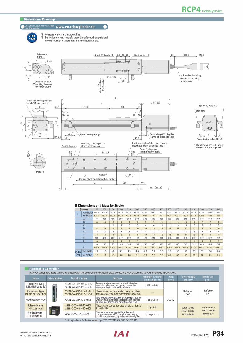