rcm turbo - strategicorp.comstrategicorp.com/files/rcmturbo/installs/sql/version 1… · web...
TRANSCRIPT

RCM TurboMaintenance Strategy Development System
User GuideRCM Turbo v14.x – SQL Version 1

General Comments..........................................................................................4Installation........................................................................................................5Existing Users - Converting current RCM Turbo files.......................................6Verify Component Codes.................................................................................7Verify Root Cause Codes.................................................................................8Verify Resources..............................................................................................9Update Component Part Definitions...............................................................11Update Root Cause Definitions......................................................................12Commencing a New RCM Turbo Assessment File........................................14Edit Component Codes..................................................................................17Edit Root Cause Definitions............................................................................19Import of Spares Data....................................................................................20Adding a New Productive Unit........................................................................21
Completing RCM Turbo Productive Unit Details.........................................30Functions & Standards................................................................................32Always click on ‘Apply’ after making changes.............................................32Functional Failures......................................................................................33Costing Assumptions...................................................................................34Productive Unit Criticality Assessment........................................................35Zonal Inspections........................................................................................36
Adding a New Maintainable Item....................................................................37Completing RCM Turbo Maintainable Item Details.....................................39Maintainable Item Criticality Assessment....................................................42
Entering Failure Mode information – Evident Failures....................................43Defining a Failure Mode..............................................................................45
FMEA Entry ‘Wizard’......................................................................................46Failure Mode Details screen........................................................................50Completing Evident Failure Data Details Table:..........................................53Breakdown Action screen............................................................................56Primary Action screen.................................................................................60Secondary Action screen............................................................................62Including Spare Parts in the analysis..........................................................64Task Frequency Optimisation......................................................................69Advanced CBM Details...............................................................................71Preferred Frequency...................................................................................75Completing Frequency Optimisation Details Table.....................................78
Breakdown Failure Data..........................................................................78Equipment Failure Data...........................................................................79Primary Action Data.................................................................................79Secondary Action Data............................................................................80
Entering Failure Mode Information - Hidden Failures.....................................81Risk Assessment for Hidden Failures.........................................................86
Auto-Grouping Facility....................................................................................87Auto-Grouping Overview.............................................................................87Create Groups Screen................................................................................92Optimise/Update Grouped Actions..............................................................97Grouping of Tasks.......................................................................................98
Ungrouping of Tasks....................................................................................107
RCM Turbo v14.x – SQL Version 2
Workload Forecasting...................................................................................109Work Requirements Histogram.................................................................111Changing Initiate Dates.............................................................................113Auto-Grouping – Selection Screen Fields Table:......................................114
Reporting within RCM Turbo........................................................................115General Navigation and Functions in RCM Turbo........................................116
Copying, Pasting, Dragging & Dropping....................................................118Optional General Display Settings............................................................119
Merging Files within RCM Turbo..................................................................120Languages Other than English.....................................................................121Other CMMS Data Transfers........................................................................123SAP CMMS Data Transfers..........................................................................124
Import of Data...........................................................................................125RCM Turbo Failure Mode Library function....................................................127
Operation of Failure Mode Data Library....................................................127Process for accessing library failure data..................................................129Process for Storing Failure Data in the Library.........................................134
Failure Mode Library Administration program...............................................137Criticality Assessment Question Set Interpretation.......................................144
Productive Unit Criticality Questions and Responses...............................144Maintainable Item Criticality Questions and Responses...........................148
RCM Turbo Assessment Templates.............................................................151Running RCM Turbo in Special Modes........................................................152User Definition and Security.........................................................................153
MySQL Administrator................................................................................153User Administration...................................................................................155Backup RCM Turbo files...........................................................................159Restore RCM Turbo files...........................................................................162Support from Strategic..............................................................................164Troubleshooting........................................................................................165
RCM Turbo v14.x – SQL Version 3
General CommentsThis User Guide is intended to be used in conjunction with and subsequent to formal training in the use of RCM Turbo.
The process of achieving plant reliability improvement is not simply an exercise in filling fields within a software application.
An understanding of formal reliability principles is required to obtain the greatest benefits from the use of RCM Turbo.
In general terms, RCM Turbo is a decision support methodology which in an asset maintenance context takes an organization from where it is today through to the delivery of new, optimized maintenance schedules ready for implementation in the CMMS.
In RCM Turbo, the base process involves:
Identifying and recording the equipment to be maintained (equipment hierarchy)Identifying and recording the functions and standards, and functional failures to be addressedEstablishing the criticality of assetsPerforming failure modes & effects analysis with a view to instigating maintenance practices aimed firmly at the minimization of business failure consequencesOptimising task frequencies in a formal and scientific mannerAssembling all the assessment data in such a format that results can be handed over to the existing Computerised Maintenance Management system for day by day operation
The following pages describe each of these steps and more. The intention is to streamline the activity so that the highest quality decisions are made and so that a clear audit trail of the basis for each and every maintenance activity is retained.
RCM Turbo v14.x – SQL Version 4
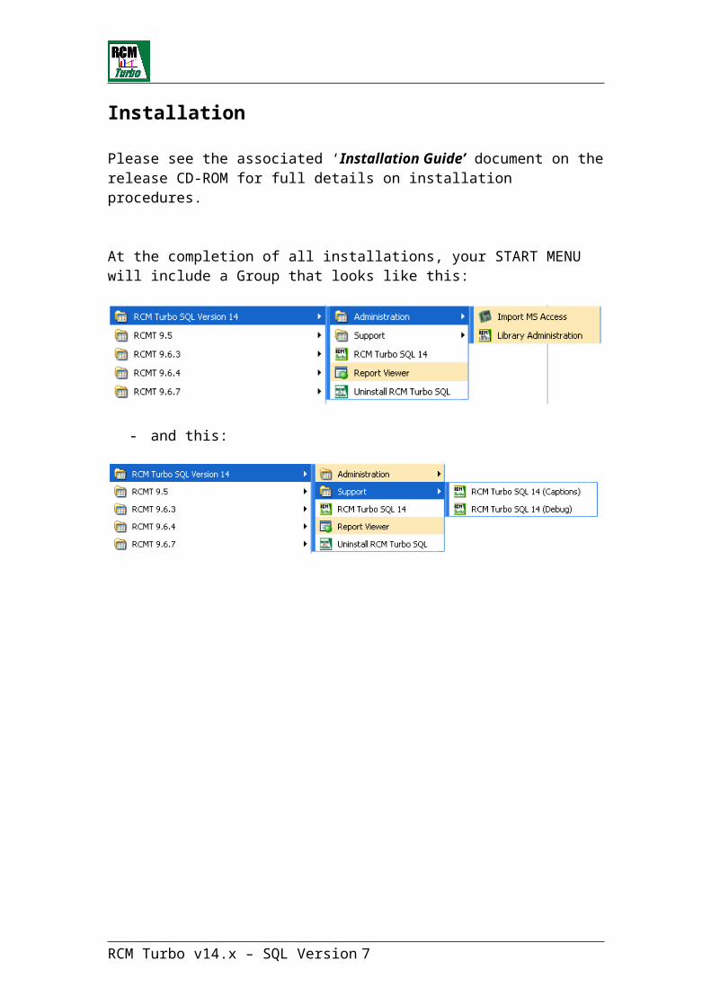
Installation
Please see the associated ‘Installation Guide’ document on the release CD-ROM for full details on installation procedures.
At the completion of all installations, your START MENU will include a Group that looks like this:
- and this:
RCM Turbo v14.x – SQL Version 5

Existing Users - Converting current RCM Turbo filesPlease see the Installation Guide for instructions on importing old RCM Turbo files.
Once an existing file has been imported to the SQL format, it can be further prepared for use with the functions that allow for the pre-definition of Component and Root Cause codes (both optional).
These processes involve the verification of data in the original file as well as the update of information to match the pre-determined codes.
For users of existing SQL versions of RCM Turbo, the Apply/Modify function should be run against any target files before using the new version.
RCM Turbo v14.x – SQL Version 6
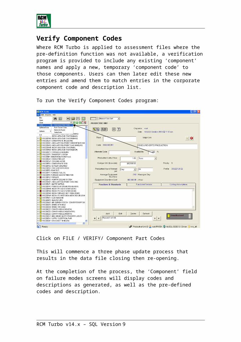
Verify Component CodesWhere RCM Turbo is applied to assessment files where the pre-definition function was not available, a verification program is provided to include any existing ‘component’ names and apply a new, temporary ‘component code’ to those components. Users can then later edit these new entries and amend them to match entries in the corporate component code and description list.
To run the Verify Component Codes program:
Click on FILE / VERIFY/ Component Part Codes
This will commence a three phase update process that results in the data file closing then re-opening.
At the completion of the process, the ‘Component’ field on failure modes screens will display codes and descriptions as generated, as well as the pre-defined codes and description.
This function can only be performed by the RCM Turbo administrator (a user with Administrative rights to the database(s)).
RCM Turbo v14.x – SQL Version 7
Verify Root Cause CodesWhere RCM Turbo is applied to assessment files where this pre-definition function was not available, a verification program is provided to include any existing ‘root causes’ and apply a new ‘root cause code’ to those failure modes. Users can then later edit these new entries and amend them to match entries in the corporate root cause code and description list.
To run the ‘Verify Root Cause Codes’ program:
Click on FILE / VERIFY/ Root Cause Codes
This will commence a three phase update process that results in the data file closing then re-opening.
At the completion of the process, the ‘Root Cause field on failure modes screens will display codes and descriptions as generated, as well as the pre-defined codes and description.
This function can only be performed by the RCM Turbo administrator (a user with Administrative rights to the database(s)).
RCM Turbo v14.x – SQL Version 8
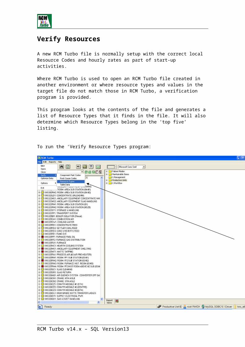
Verify Resources
A new RCM Turbo file is normally setup with the correct local Resource Codes and hourly rates as part of start-up activities.
Where RCM Turbo is used to open an RCM Turbo file created in another environment or where resource types and values in the target file do not match those in RCM Turbo, a verification program is provided.
This program looks at the contents of the file and generates a list of Resource Types that it finds in the file. It will also determine which Resource Types belong in the ‘top five’ listing.
To run the ‘Verify Resource Types program:
Click on FILE / VERIFY/ Resource Types
This will commence a two phase update process that results in the data file closing then re-opening.
RCM Turbo v14.x – SQL Version 9

At the completion of the process, the Resource Types table will be populated with values found in the file.
This function can only be performed by the RCM Turbo administrator (a user with Administrative rights to the database(s)).
RCM Turbo v14.x – SQL Version 10

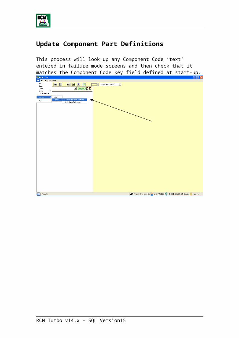
Update Component Part Definitions
This process will look up any Component Code ‘text’ entered in failure mode screens and then check that it matches the Component Code key field defined at start-up.
RCM Turbo v14.x – SQL Version 11

Update Root Cause Definitions
This process will look up any Root Cause ‘text’ entered in failure mode screens and then check that it matches the Root Cause Code key field defined at start-up.
RCM Turbo v14.x – SQL Version 12
New Users – no existing RCM Turbo files
If you are a new user of RCM Turbo, after the installations described above you are ready to begin use of the system.
Click on the RCM Turbo screen icon or activate the program from the START / Programs menu.
The toolbar items on this screen are described as follows:
Create a New File
Open Existing FileMerge RCM Turbo files together
On-line Help
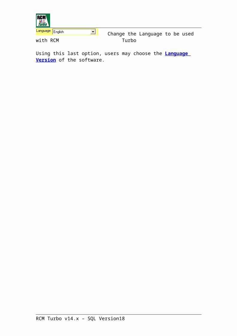
Change the Language to be used with RCM Turbo
Using this last option, users may choose the Language Version of the software.
RCM Turbo v14.x – SQL Version 13
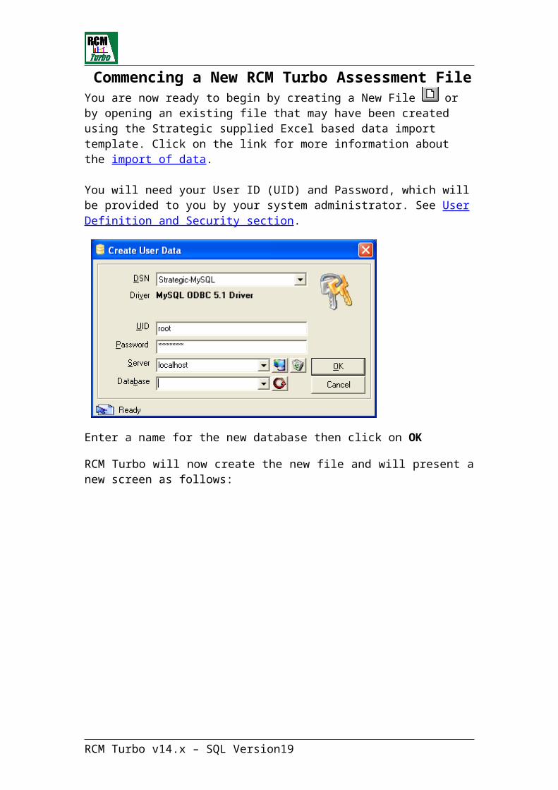
Commencing a New RCM Turbo Assessment FileYou are now ready to begin by creating a New File or by opening an existing file that may have been created using the Strategic supplied Excel based data import template. Click on the link for more information about the import of data.
You will need your User ID (UID) and Password, which will be provided to you by your system administrator. See User Definition and Security section.
Enter a name for the new database then click on OK
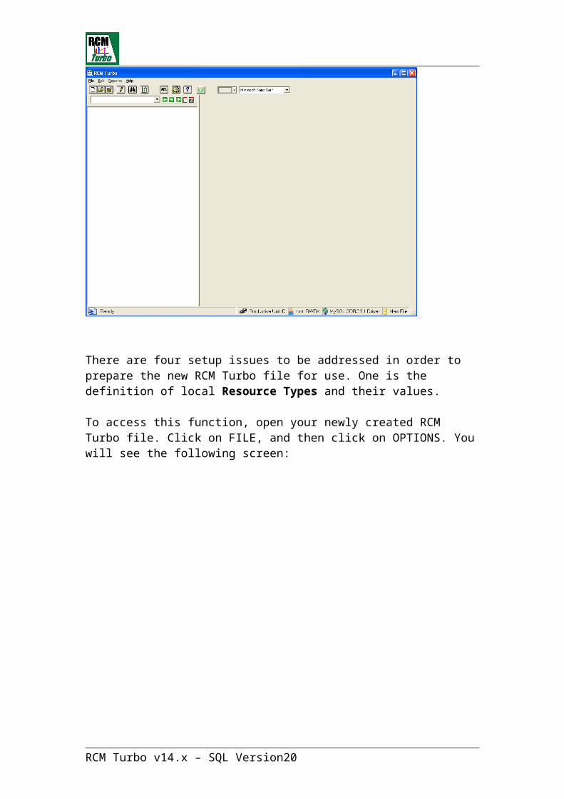
RCM Turbo will now create the new file and will present a new screen as follows:
RCM Turbo v14.x – SQL Version 14
There are four setup issues to be addressed in order to prepare the new RCM Turbo file for use. One is the definition of local Resource Types and their values.
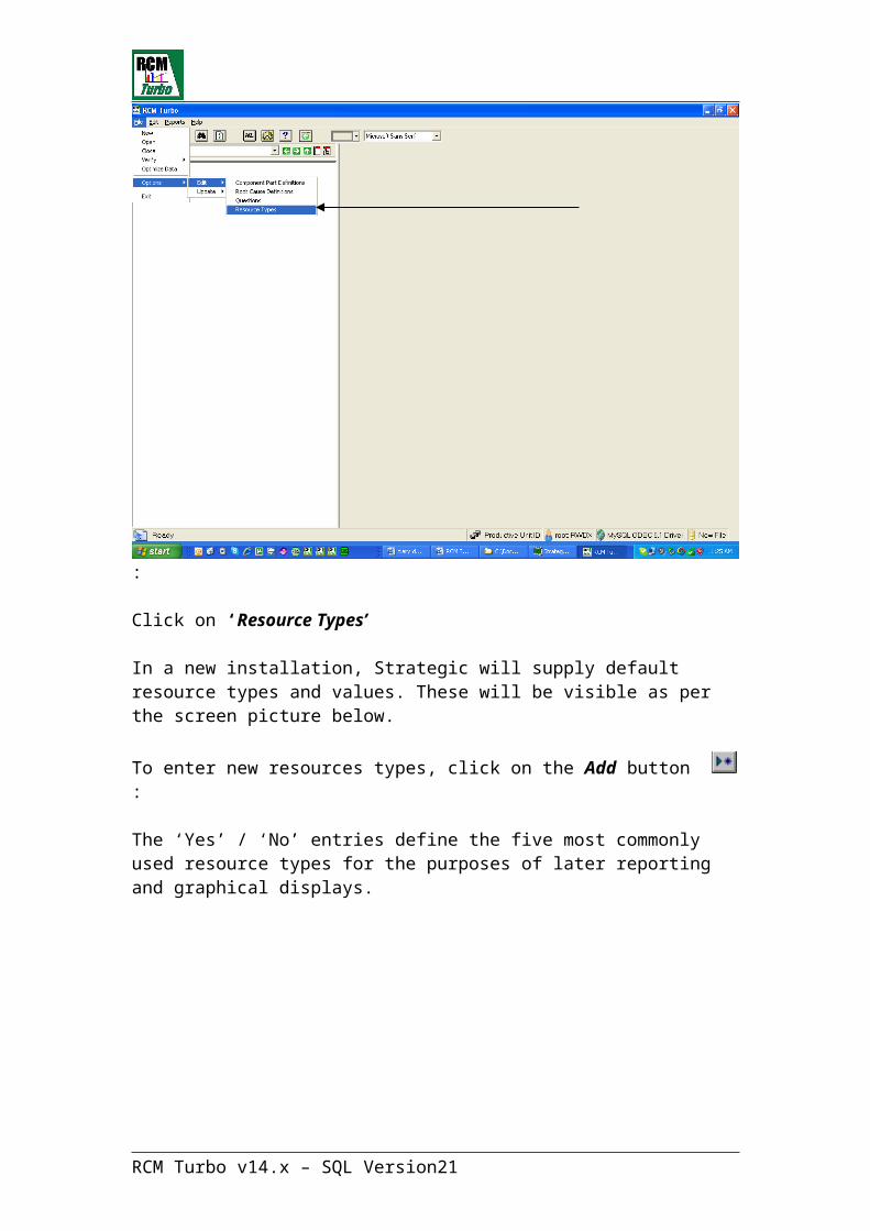
To access this function, open your newly created RCM Turbo file. Click on FILE, and then click on OPTIONS. You will see the following screen:
:
Click on ‘Resource Types’
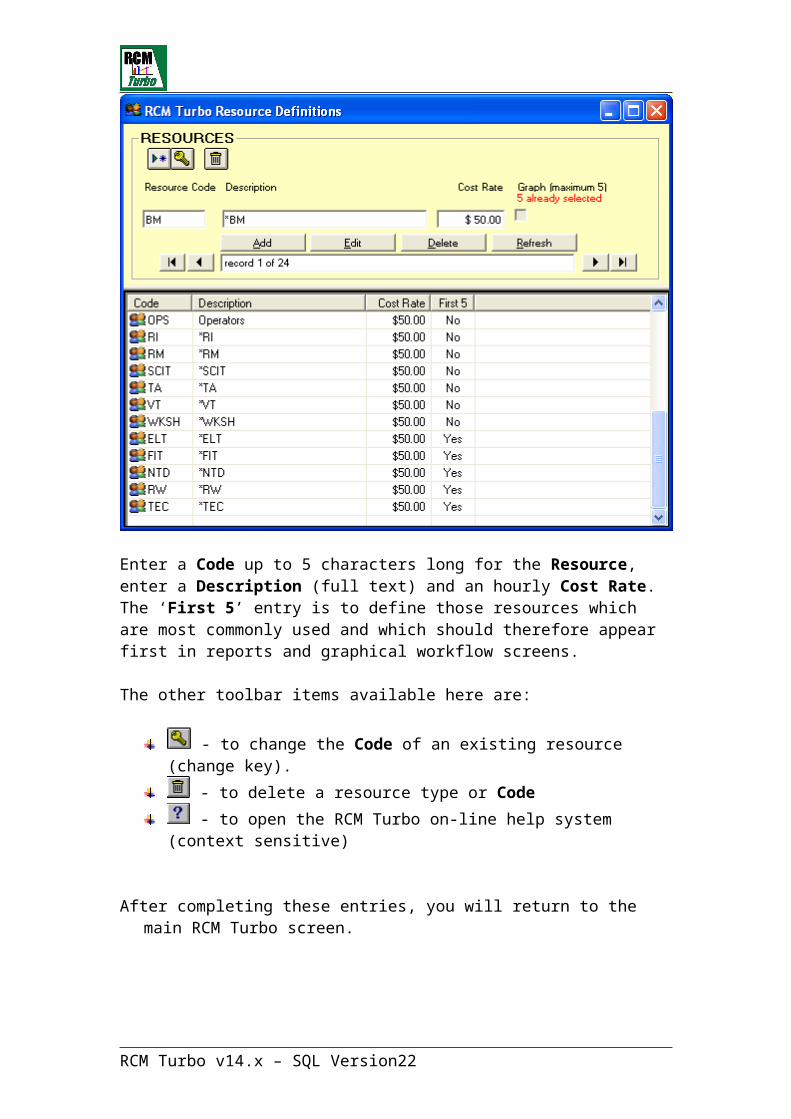
In a new installation, Strategic will supply default resource types and values. These will be visible as per the screen picture below.
To enter new resources types, click on the Add button :
The ‘Yes’ / ‘No’ entries define the five most commonly used resource types for the purposes of later reporting and graphical displays.
RCM Turbo v14.x – SQL Version 15

Enter a Code up to 5 characters long for the Resource, enter a Description (full text) and an hourly Cost Rate. The ‘First 5’ entry is to define those resources which are most commonly used and which should therefore appear first in reports and graphical workflow screens.
The other toolbar items available here are:
- to change the Code of an existing resource (change key). - to delete a resource type or Code - to open the RCM Turbo on-line help system (context sensitive)
After completing these entries, you will return to the main RCM Turbo screen.
RCM Turbo v14.x – SQL Version 16

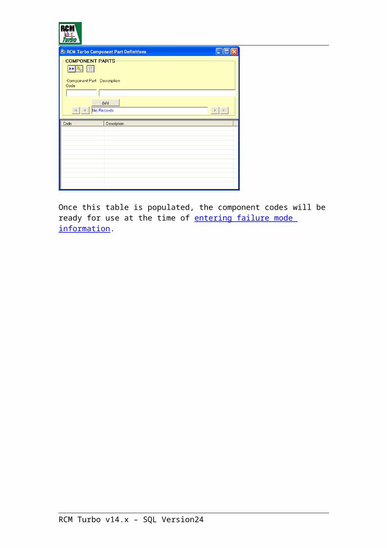
Edit Component CodesRCM Turbo includes an optional function which allows for the pre-definition of component codes and descriptions used in the failure mode assessment screens.
The ‘component’ field is the first entry on the Failure Mode assessment screen.
Component codes are routinely utilized by the SAP PM module.
The component and associated code is stored within an RCM Turbo system file
Click on ‘Component Code Definitions’
RCM Turbo v14.x – SQL Version 17
Once this table is populated, the component codes will be ready for use at the time of entering failure mode information.
RCM Turbo v14.x – SQL Version 18
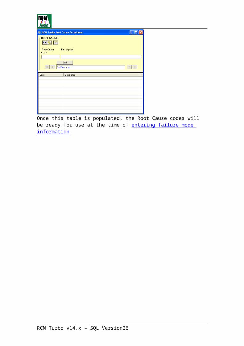
Edit Root Cause Definitions
Click on ‘Root Cause Definitions’
RCM Turbo includes a function which allows for the pre-definition of root cause codes and descriptions used in the failure mode assessment screens.
Root cause codes are routinely utilized by the SAP PM module.
The component and associated code is stored within an RCM Turbo system file.
Once this table is populated, the Root Cause codes will be ready for use at the time of entering failure mode information.
RCM Turbo v14.x – SQL Version 19
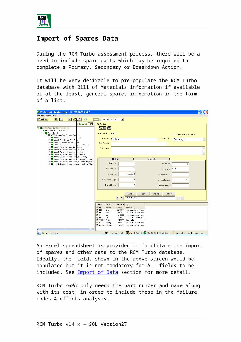
Import of Spares Data
During the RCM Turbo assessment process, there will be a need to include spare parts which may be required to complete a Primary, Secondary or Breakdown Action.
It will be very desirable to pre-populate the RCM Turbo database with Bill of Materials information if available or at the least, general spares information in the form of a list.
An Excel spreadsheet is provided to facilitate the import of spares and other data to the RCM Turbo database. Ideally, the fields shown in the above screen would be populated but it is not mandatory for ALL fields to be included. See Import of Data section for more detail.
RCM Turbo really only needs the part number and name along with its cost, in order to include these in the failure modes & effects analysis.
If you have the Spares Optimisation System (SOS), all these fields will eventually be needed by that system.
RCM Turbo v14.x – SQL Version 20
In the absence of an imported equipment hierarchy, we are now ready to begin entering information.
Adding a New Productive Unit
Use the right mouse button anywhere in the left panel to enter a new Productive Unit
You will see the following sub-screen:
The code here should exactly match the code used in your CMMS to describe a Productive Unit within the equipment hierarchy.
A Productive Unit is any level of process equipment that can be defined in terms of its Functional performance. It is usually made up of a number of
RCM Turbo v14.x – SQL Version 21
lower level pieces of equipment, such as motors and gearboxes (these are called Maintainable Items).
It is not critical what level of equipment is identified as a Productive Unit. If this is set at a very high level though, each PU will have many Maintainable Items (MI's). If it is set at a very low level, the each PU will only have one or two MI's. The important thing is to be able to understand what has been defined, and to not miss any of the equipment or process.
Note that a PU can be referenced as the ‘parent’ of another PU, creating unlimited levels of hierarchy if required. The process for doing this is explained later in this manual.
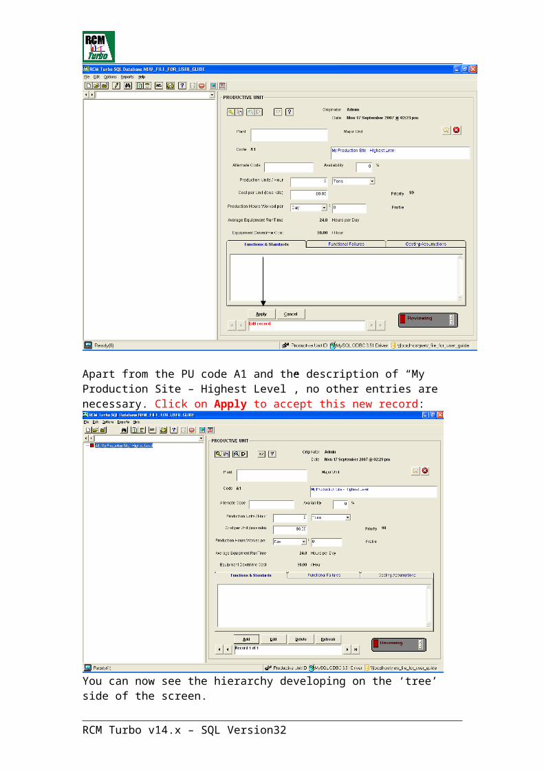
Here, we will create a new Productive Unit with a Code of <A1>. We will be creating a hierarchy of equipment beginning at the highest level.
RCM Turbo v14.x – SQL Version 22

You will now see the layout template for RCM Turbo data display. The left hand pane (or tree view) will be populated with equipment hierarchy information while the right hand side will always display the data selected from the tree.
When we complete this first item of equipment, it will appear in the tree view.
Because this first Productive Unit is intended to be the highest level in the site, we will make entries as follows:
Apart from the PU code A1 and the description of “My Production Site – Highest Level”, no other entries are necessary. Click on Apply to accept this new record:
RCM Turbo v14.x – SQL Version 23
You can now see the hierarchy developing on the ‘tree’ side of the screen.
To begin adding lower levels of Productive Unit to this ‘tree’, highlight the existing PU (A1) and use the right mouse button to add another new Productive Unit:
Entering another code here (A01) presents the following screen:
RCM Turbo v14.x – SQL Version 24

Any new entry within RCM Turbo will display a description of <new>. Overtype this to enter the required Productive Unit name.
RCM Turbo v14.x – SQL Version 25
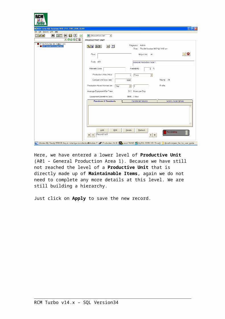
Here, we have entered a lower level of Productive Unit (A01 – General Production Area 1). Because we have still not reached the level of a Productive Unit that is directly made up of Maintainable Items, again we do not need to complete any more details at this level. We are still building a hierarchy.
Just click on Apply to save the new record.
RCM Turbo v14.x – SQL Version 26
Now we have two higher levels of hierarchy. We could continue in this same way to build a larger hierarchy.
To define how Productive Units should have ‘parents’ and ‘children’, we use the Major Unit field in the Productive Unit screen.
On the Productive Unit screen, there are two buttons that can be used.
The first is used to ‘set’ a major unit for the target Productive Unit. Using this
icon , we can add the current Productive Unit to the hierarchy tree as part of a Major Unit (or higher level Productive Unit) selected from a list:
In our new file, there are two Major Units to choose from. We have already made PU A01 a ‘child’ of PU A1.
RCM Turbo v14.x – SQL Version 27

The second icon is used to undo any parent/child relationship defined in
the file. Clicking on will remove any Major Unit link entries for this Productive Unit and restore the tree to a non-hierarchical (or straight line) display.
To return to our developing equipment hierarchy, you will see that the equipment hierarchy tree now looks like this:
The small square shaped icons indicate Productive Units. The Red colour indicates the analysis status of the Productive Unit (red = incomplete –see below for further explanation of the use of colour codes). The + and – signs indicate your ability to ‘open’ or ‘close’ the hierarchy.
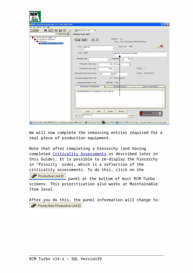
We will now add a lower level Productive Unit ‘A0001’ / ‘Bauxite Feed Conveyor System, this time one which has Maintainable Items directly attached to it:
RCM Turbo v14.x – SQL Version 28

We will now complete the remaining entries required for a real piece of production equipment.
Note that after completing a hierarchy (and having completed Criticality Assessments as described later in this Guide), it is possible to re-display the hierarchy in “Priority” order, which is a reflection of the criticality assessments.
To do this, click on the panel at the bottom of most RCM Turbo screens. This prioritisation also works at Maintainable Item level.
After you do this, the panel information will change to:
RCM Turbo v14.x – SQL Version 29

Completing RCM Turbo Productive Unit Details
PU Code- Typically a code from a hierarchical plant register/index representing the Productive Unit is displayed, followed by a text description of the Productive Unit. You will have entered these details as part of the Add/New Productive Unit function described earlier.
Plant- A free text field. Typically a description from a hierarchical plant register/index
Major Unit-A description from a hierarchical plant register/index representing the Major Unit i.e. parent of the Productive Unit. You will have entered these details as part of the Major Unit function described earlier.
Alternate Code-Typically used as an alternative to the plant hierarchy codes or any similar type code as applicable. There may be other local naming conventions used to describe a location for instance. This is a free text field.
Availability-The required availability of the Productive Unit expressed as a percentage and is usually dictated by production requirements. This is not always 100% Prod. Units/hour-The production rate per hour of operation
Units-Use the drop-down selection scroller to select the required unit of measure for production or service
Cost per Unit (Loss Rate)-Cost to produce the product per Unit. Note this is intended to represent the loss to the business for non-production. It should be considered an average cost.
Production Hours-Number of hours normally worked per day, week, month, year (average) – use the drop-down box to make your selection
Average Equipment Run Time- Result of RCM Turbo calculation from the above entries
Equipment Downtime Cost-RCM Turbo generated i.e. downtime cost/hour x hours worked. This value will be used in the assessment of any equipment falling below this level in the hierarchy.
RCM Turbo Priority-RCM Turbo generated rating of criticality i.e. 1(high) to 16 (low). A value of ‘99’ indicates that this Productive Unit has not yet had its criticality assessed.
Profile-The RCM Turbo criticality questions responses profile – blank if criticality assessment not yet performed.
RCM Turbo v14.x – SQL Version 30

Originator-The name of the user who entered or updated the details of this Productive Unit.
Date-Date the assessment was developed on or last updated.
Use this button to define the Analysis Status. The user may choose between Reviewing, Un-Authorised and Complete. Note this will change the colour of the icons in the tree view accordingly.
The next screen is the result of data entry in keeping with the above definitions and the concept that a Productive Unit should be defined as “an item of plant with a definable output”:
This conveyor moves 550 tonnes per hour at a loss rate of $3.64 per tonne. It operates 24 hours per day.
We should now complete the other details that relate to this Productive Unit.
RCM Turbo v14.x – SQL Version 31
Functions & Standards
Firstly define the boundaries of the Productive Unit. It is important that all users understand where each PU starts and where it finishes. This will also help to ensure that no part of the equipment is left out of the analysis.
Secondly define the functional (or process) requirements of this productive unit in RCM terms.
Click on the Functions & Standards tab to make these entries:
Always click on ‘Apply’ after making changes.
RCM Turbo v14.x – SQL Version 32

Functional Failures
This is one of the most important fields in the RCM analysis process. Users should indicate at what stage/point the item fails to meet its functional requirements.
This should include both Primary and Secondary Functions as appropriate.
The list is likely to start with such items as: Fails to Start on Demand, Fails to Operate Continuously, Fails to Stop on Demand. It should then continue with any state where it is still running but…
RCM Turbo v14.x – SQL Version 33
Costing Assumptions
Comments on the calculation of production loss value for future reference, update and audit trail purposes.
RCM Turbo v14.x – SQL Version 34

Productive Unit Criticality Assessment
Where we have entered (or imported) a complete hierarchy, it is desirable to perform a criticality assessment at Productive Unit level. This process is used to prioritise the assets and make the first decision in the analysis – “where should we start?”
Use the Review button to start the criticality assessment process.
To establish the RCM Turbo criticality of a productive unit, work through the question set. These will have been tailored for your environment by Strategic personnel or by your senior maintenance planner.
At any point in the question set, you can use the 'Previous' button to step back through the answers, change a value and then continue.
Note that RCM Turbo will warn against illogical answers (it has logic checks built in).
If the item has already been reviewed, RCM Turbo will retrace the last RCM Turbo profile - the record of the answers given in the previous RCM Turbo review of the item.
At the end of the question sequence, RCM Turbo will display the criticality scale expressed as a number between 1 (most critical) and 16.
Remember to click on ‘Apply’ to save your responses.
Click here for detailed information about criticality assessment at Productive Unit level.
The Productive Unit criticality ranking represents a higher level ‘business based’ assessment of criticality. A further criticality assessment at Maintainable Item level will be conducted at that level, to establish the ‘technical’ criticality of those items in terms of failure characteristics, measurability, inspectability etc.
See the Maintainable Item section of this manual for more information about this.
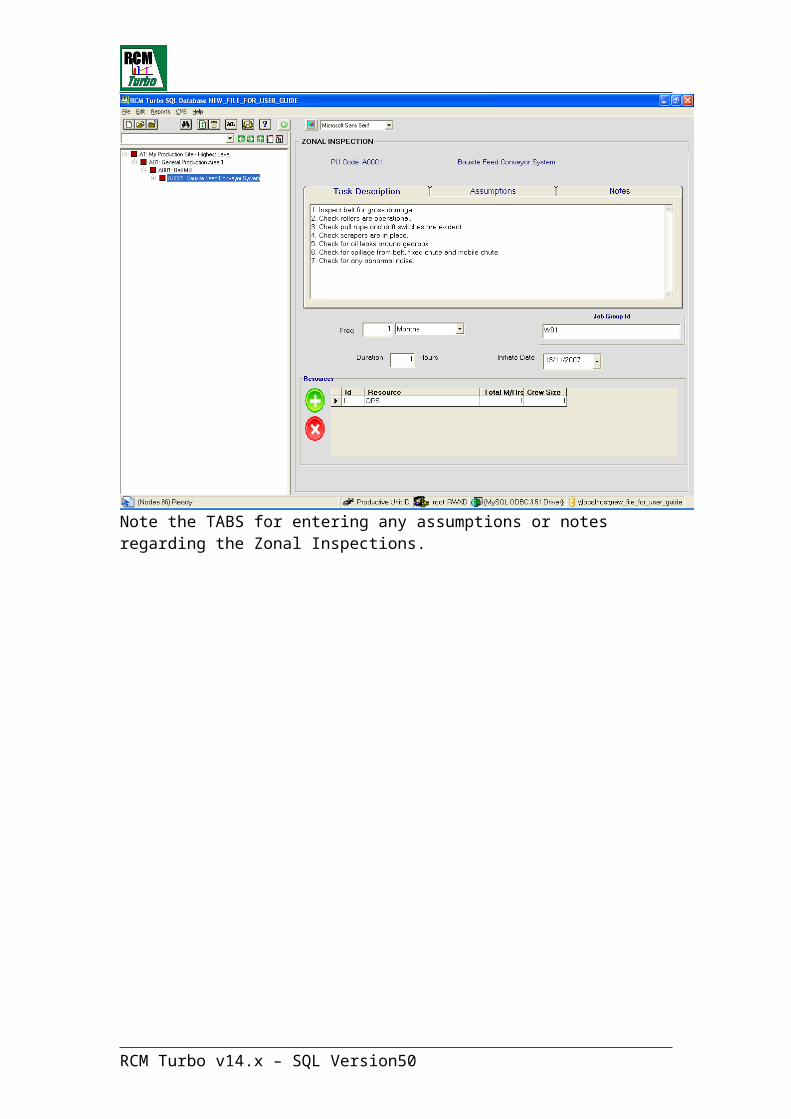
The other entry made at Productive Unit level is that which details Zonal Inspections:
RCM Turbo v14.x – SQL Version 35

Zonal Inspections
Zonal Inspections are tasks that are linked directly to an area of plant and which are not normally optimised for frequency. They are often ‘walk-arounds’, security checks etc and will include simple visual and aural checks at that level.
Click on the Icon to display the Zonal Inspection sub-screen.
Record any general inspections or tasks that can be carried out at Productive Unit Level. Enter the task description, its required frequency, duration and the resources required to perform the task. Zonal Inspections will become part of a Job Group (see Workflow section later in this manual).
Entries made here normally occur at the time of general failure modes & effects analysis, discussed later in this manual.
The Zonal Inspection Screen:
Note the TABS for entering any assumptions or notes regarding the Zonal Inspections.
RCM Turbo v14.x – SQL Version 36

Adding a New Maintainable ItemA Maintainable Item is normally the lowest level recognised as a unit or assembly by the maintenance personnel. Typical examples are motors, gearboxes and pump units.
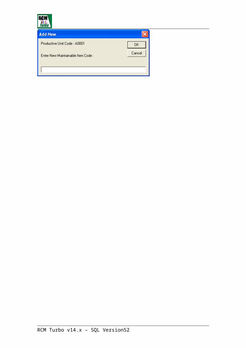
To add Maintainable Items to an existing Productive Unit, highlight the target Productive Unit using the right mouse button as follows:
This action will display the following new entry screen:
RCM Turbo v14.x – SQL Version 37

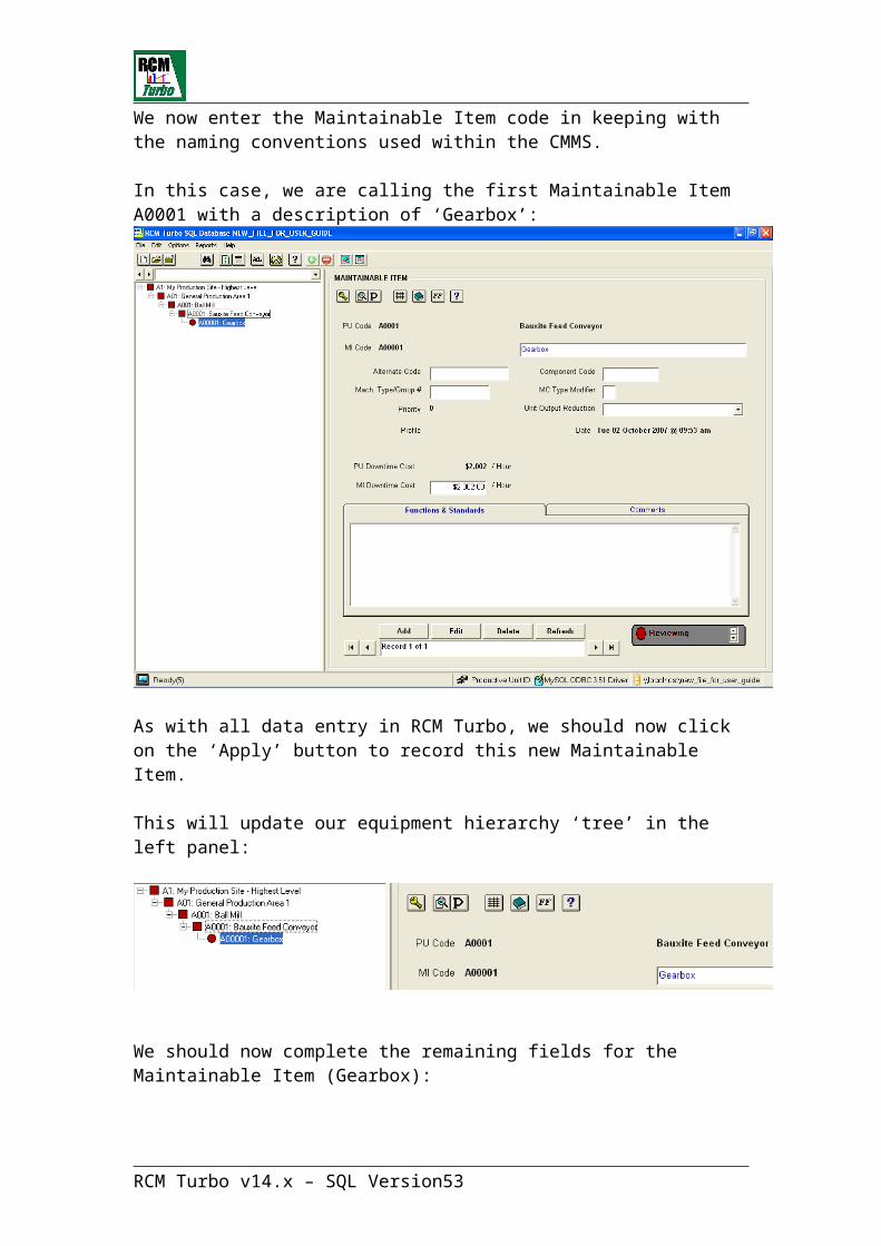
We now enter the Maintainable Item code in keeping with the naming conventions used within the CMMS.
In this case, we are calling the first Maintainable Item A0001 with a description of ‘Gearbox’:
As with all data entry in RCM Turbo, we should now click on the ‘Apply’ button to record this new Maintainable Item.
This will update our equipment hierarchy ‘tree’ in the left panel:
We should now complete the remaining fields for the Maintainable Item (Gearbox):
RCM Turbo v14.x – SQL Version 38
Completing RCM Turbo Maintainable Item Details
Analysis Status The user may choose between Reviewing, Un-Authorised and Complete. Note this will change the colour of the icons in the tree view accordingly.
Productive Unit Data brought forward from your Productive Unit entryDescription The description of the Productive Unit is displayedMI Code Typically a code from a hierarchical plant register/index representing the Maintainable ItemDescription A description of the Maintainable ItemAlternate Code Typically used to identify MI’s which belong to the same group or that would normally be stopped together or some similar purpose.Machine Type/Group# A generic code used for sourcing failure data from the library.M/C Type Modifier Used as a modifier to a Machine Type/Group code Component Code Typically used for reference to external maintenance management systems RCM Turbo Priority RCM Turbo generated rating of criticality i.e. 1 (high) to 16 (low)
Unit Output Reduction Should this MI fail, what will be the effect on production ('Total Stoppage', 'Part Stoppage or Quality', 'No Immediate Effect' or 'No Effect'). Note that the selection made here will impact the frequency optimisation calculations by multiplying the Downtime Cost by 1, 0.66, 0.33 or zero respectively.
RCM Turbo Profile The RCM Turbo criticality response profile. Note that the first 12 answers in this profile will be shared with SOS. Whichever system is used first to answer the MI questions, these answers will be defaulted to the other system where any further changes may be made without affecting the other system.Date Date assessed or last updatedPU Downtime CostDefault value from Productive Unit. Used in the Frequency Optimisation FacilityMI Downtime Cost Field value defaults from PU Downtime Cost. May be changed by user if different value required. Used in Frequency Optimisation calculations.Functions & Standards A general text field in RCM terms usually only used to expand on the data entered against the parent PU, again usually only where the parent is very large or complex.Comments A general text field for comments as required
The following toolbar options are available on the MI details, in addition to those on the PU details screen,
RCM Turbo v14.x – SQL Version 39
Click on this 'Matrix' button to display the maintenance planning matrix generated by RCM Turbo for this item.
Click the 'Library' button to utilise the generic Failure Data Library facility to store or recall failure data.
The FF or Functional Failure button presents a screen showing three tabs, one for each of the following fields; Functions and Standards for the parent PU, Functional Failures for the parent PU, Functions & Standards for the MI. All three fields can be updated from this screen.
Click on this icon to enter or review spares associated with this item. This will have the effect of building a Spares List (or Bill-Of-Material) for this Maintainable Item (MI). Note that this MI Spares List will be displayed for selection purposes on the Maintenance Action Spares List screen. Also note that any items added to that screen will automatically be added to this MI Spares List. This list of spares associated with this MI will also appear in SOS, along with the answers given to the first 12 MI questions.
RCM Turbo v14.x – SQL Version 40

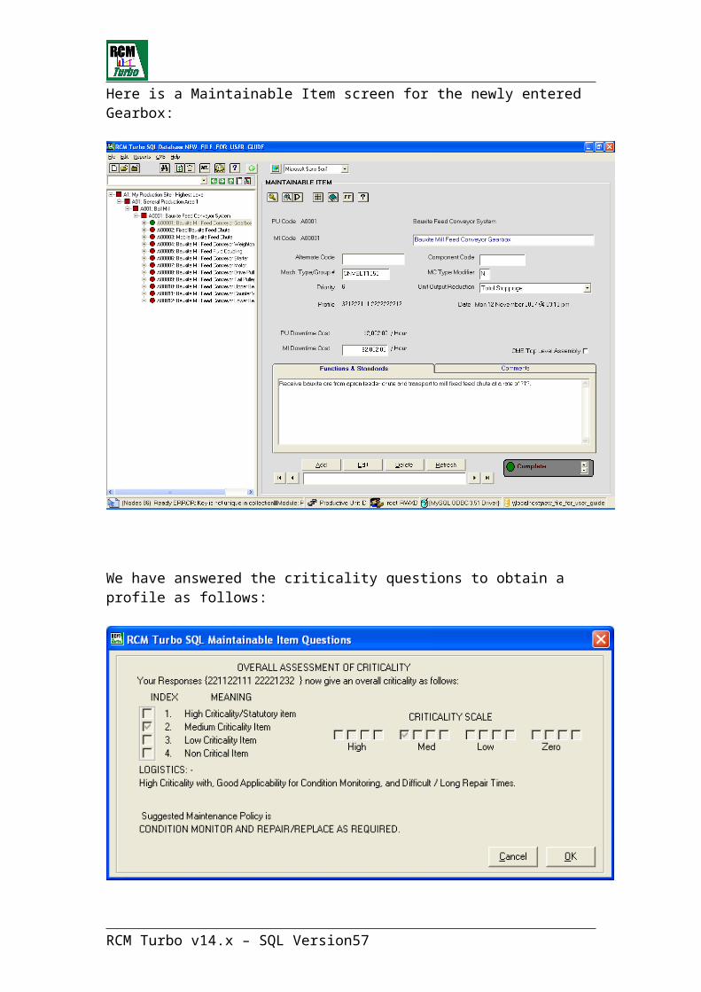
Here is a Maintainable Item screen for the newly entered Gearbox:
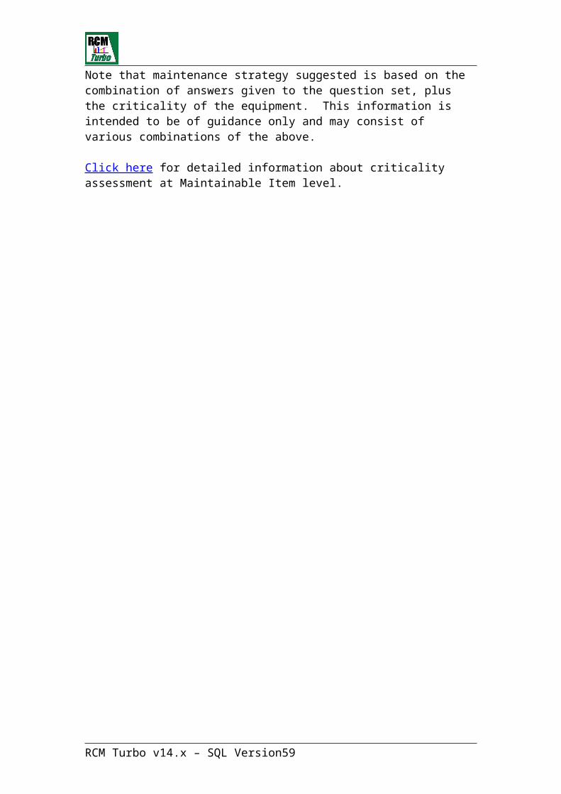
We have answered the criticality questions to obtain a profile as follows:
RCM Turbo v14.x – SQL Version 41

Maintainable Item Criticality AssessmentTo assess the criticality of a maintainable item, work through the question sets.
To do this, click on the Review button
The first series of questions are the same as used in at the PU level and the answers given will be defaulted to the MI.
If the item has already been reviewed, RCM Turbo will retrace the last RCM Turbo profile - the record of the answers given in the previous RCM Turbo item review.
At the end of the question sequence, RCM Turbo will display the criticality scale. The criticality of the item will give you a good guide as to whether you need to devote further time to the assessment of the item, relative to other more critical items.
Note that the first 12 answers in this profile will be shared with SOS. Whichever system is used first to answer the MI questions, these answers will be defaulted to the other system where any further changes may be made without affecting the other system.
When you are satisfied with your answers RCM Turbo will display further findings and will give you the option to view the Maintenance Strategy Matrix.
Remember to click on ‘Apply’ to save your responses.
Example of RCM Turbo Maintenance Strategy Matrix
Note that maintenance strategy suggested is based on the combination of answers given to the question set, plus the criticality of the equipment. This information is intended to be of guidance only and may consist of various combinations of the above.
Click here for detailed information about criticality assessment at Maintainable Item level.
RCM Turbo v14.x – SQL Version 42
Entering Failure Mode information – Evident FailuresThis is the lowest level of the analysis process. It is here that the bulk of the analysis will take place.
It is important that only failures that result in a Functional Failure of the process (as entered in the appropriate field at the parent PU level) are considered. If such a link cannot be made, then it should not be considered. (Alternatively this may mean that the list of Functional Failures is incomplete and it would be recommended that further time be spent extending the list.) In addition it is important that all Functional Failures are addressed by the maintenance actions, so a review of this list is highly recommended as a check. A button on the toolbar , will take the user directly to the parent PU’s Functional Failure text to assist in this review.
It is also important that when establishing and entering failure modes only original or primary failures are considered. If the failure being identified will only occur as the result of another failure, then it is a secondary or consequential failure and not of interest to this analysis. Part of the logic behind this is that if all primary failures are predicted or prevented then there will not be any consequential failures to worry about.
Further, all potential failures should be considered. Users should not restrict the analysis only to those failures that have occurred, but also consider those that could occur.
To add a new Failure Mode to an existing Maintainable Item, highlight the MI and using the right mouse button, select “Add New – Failure Mode”
This will present the following screen:
RCM Turbo v14.x – SQL Version 43

RCM Turbo will allocate failure mode numbers commencing at ’01’
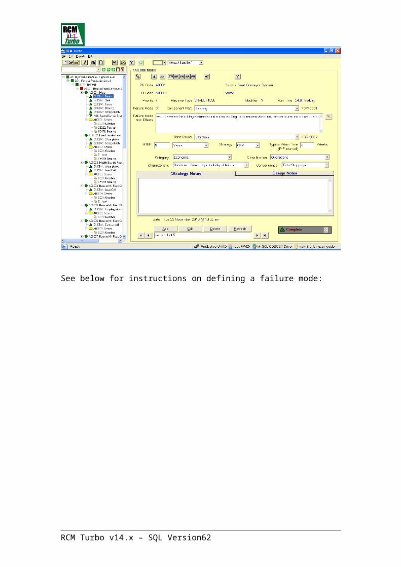
We can now begin entering evident failure mode information for a bearing failure:
See below for instructions on defining a failure mode:
RCM Turbo v14.x – SQL Version 44

Defining a Failure ModeAn individual failure mode consists of the failed Component, the Failure Mode & Effect and the Root Cause. Should any one of these be changed then you will have identified another, separate failure mode.
Note that Motors do not fail! It is the bearings within Motors that fail, etc. hence the need to specify the Component in the failure mode. Also make sure that only original component failures are considered, not secondary or consequential failures. (If the original failure can be averted then there should never be any secondary failures!) Look only for credible failures. Do not become concerned with the incredible. Lastly make sure you address all potential failures and not restrict the analysis to those failures that have occurred in the past.
The Failure Mode & Effect should be a very structured description of the failure mode, i.e. it should start with the mechanism of the failure, followed by the various stages or progression of the failure, i.e. how does the failure start to become evident, how does it progress and what does it lead to? Finally the description should include the final stage of the failure, if not addressed, at which point there is actual lost of function. Writing the Failure Mode & Effect in this way can help to establish an appropriate predictive maintenance action. If you can enter a (part) sentence which includes the words ‘… leading to …’ or ‘… resulting in …’ and end with a reference to the related Functional Failure, then you are likely to have developed a good Failure Mode & Effect.
The Root Cause should be relatively generic and the list kept short. In this way a list can be established which might be useful for future analysis purposes, i.e. this list should be reproduced in your CMMS. If the list were too long then it would become unwieldy. Remember that you are trying to get a feel for the reason for the failure so as to establish the best way to predict or prevent it. This is not a detailed Root Cause analysis, which would normally only be performed on specific failures and therefore only on the most critical equipment.
It is important that when establishing and entering failure modes only original or primary failures are considered. If the failure being identified will only occur as the result of another failure, then it is a secondary or consequential failure and not of interest to this analysis. Part of the logic behind this is that if all primary failures are predicted or prevented then there will be not consequential failures to worry about.
Before moving to the next screen, it is important to consider whether it would be reasonable or even possible to eliminate this failure mode. It is for this reason the free text fields appear at the bottom of this screen. Any thoughts that come to mind regarding a change of design or operating procedure, etc. should be entered here for possible future investigation or action.
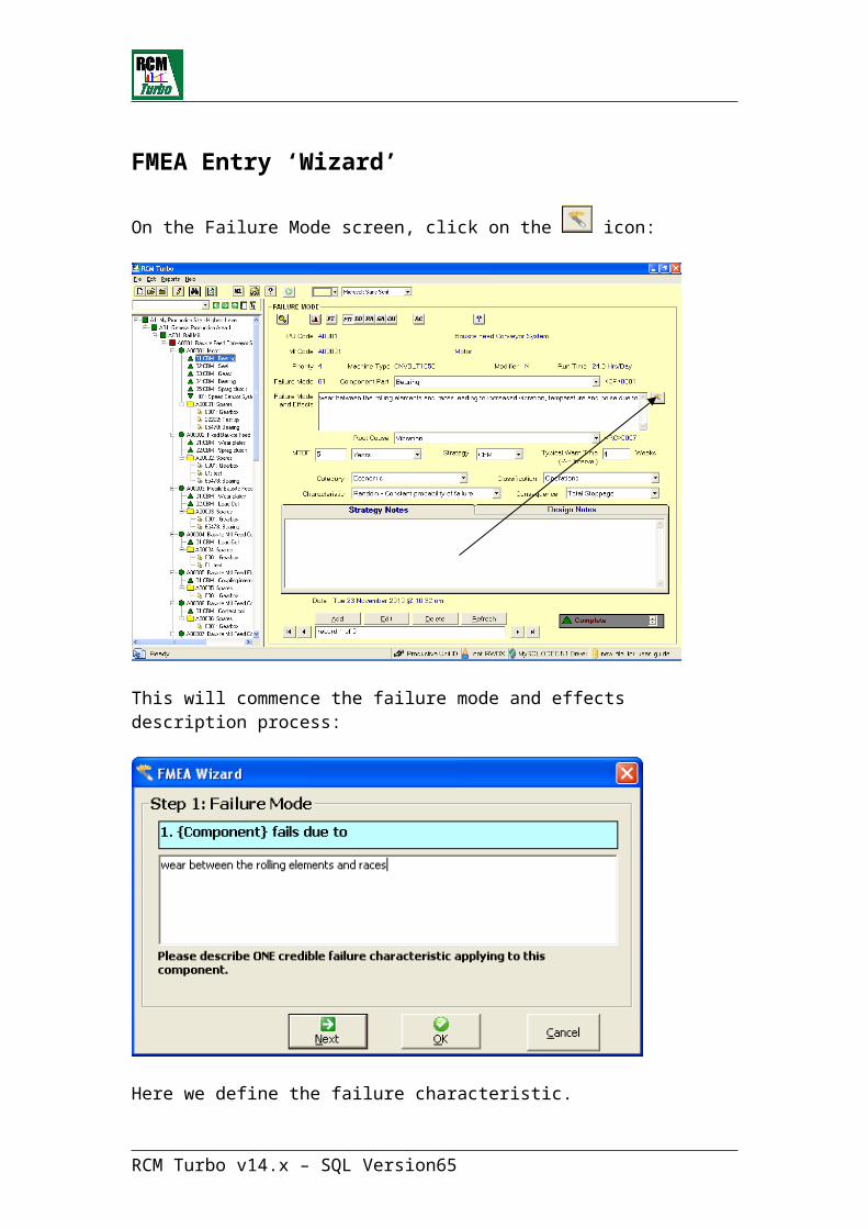
To assist in the correct definition of a failure modes and its effect, RCM Turbo includes an (optional) FMEA Entry ‘Wizard’:
RCM Turbo v14.x – SQL Version 45
FMEA Entry ‘Wizard’
On the Failure Mode screen, click on the icon:
This will commence the failure mode and effects description process:
Here we define the failure characteristic.
Click on ‘Next’
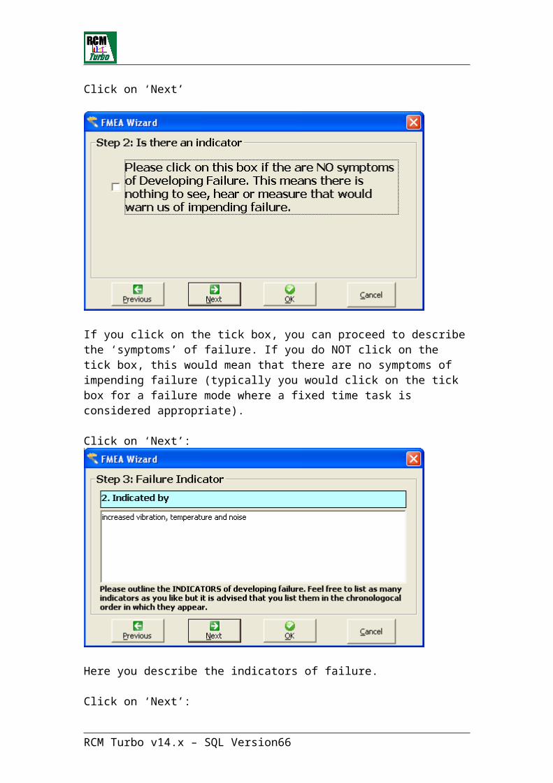
RCM Turbo v14.x – SQL Version 46
If you click on the tick box, you can proceed to describe the ‘symptoms’ of failure. If you do NOT click on the tick box, this would mean that there are no symptoms of impending failure (typically you would click on the tick box for a failure mode where a fixed time task is considered appropriate).
Click on ‘Next’:
Here you describe the indicators of failure.
Click on ‘Next’:
RCM Turbo v14.x – SQL Version 47
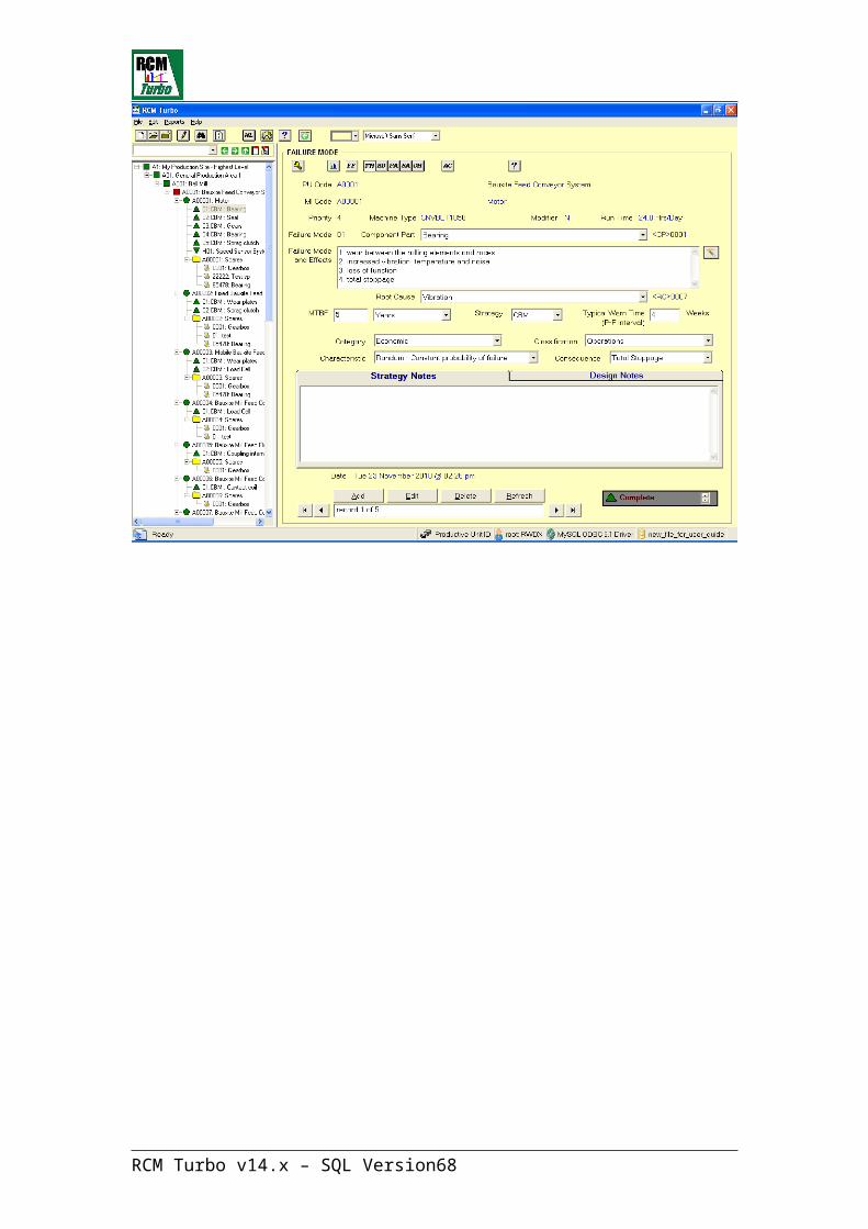
After completing the wizard and clicking in ‘Finish’, we now have a failure mode looking like this:
RCM Turbo v14.x – SQL Version 48

RCM Turbo v14.x – SQL Version 49
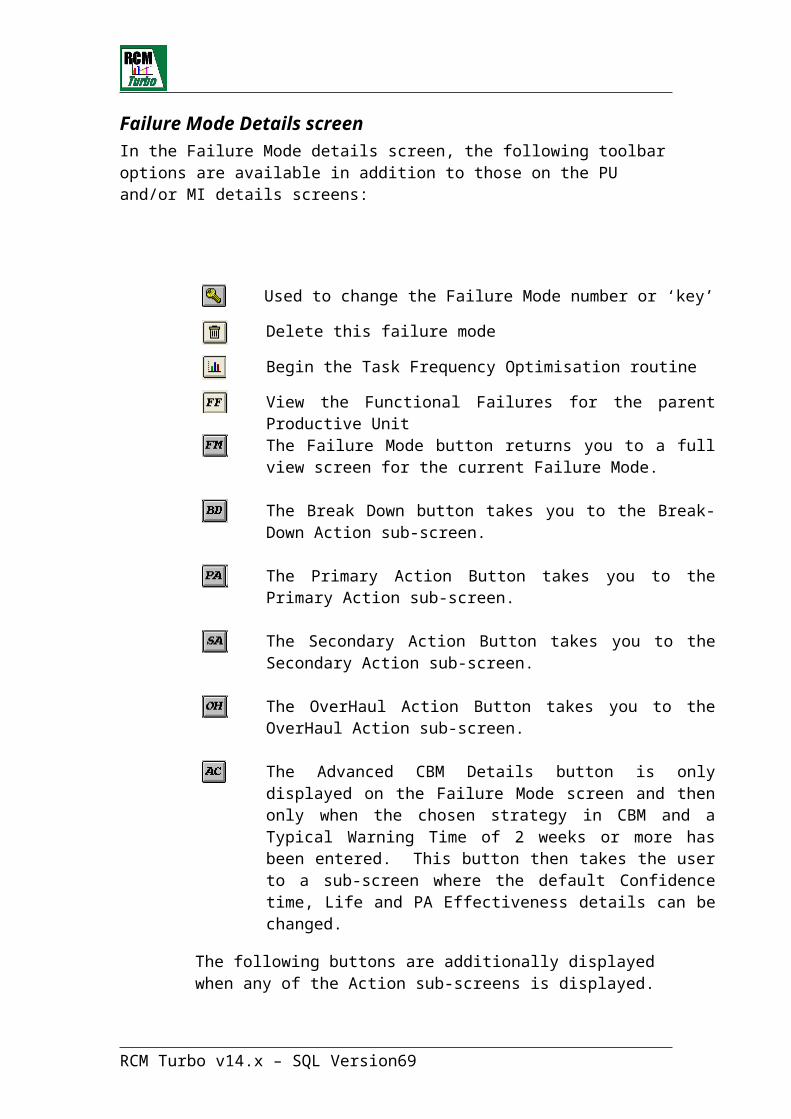
Failure Mode Details screenIn the Failure Mode details screen, the following toolbar options are available in addition to those on the PU and/or MI details screens:
Used to change the Failure Mode number or ‘key’
Delete this failure mode
Begin the Task Frequency Optimisation routine
View the Functional Failures for the parent Productive Unit
The Failure Mode button returns you to a full view screen for the current Failure Mode.
The Break Down button takes you to the Break-Down Action sub-screen.
The Primary Action Button takes you to the Primary Action sub-screen.
The Secondary Action Button takes you to the Secondary Action sub-screen.
The OverHaul Action Button takes you to the OverHaul Action sub-screen.
The Advanced CBM Details button is only displayed on the Failure Mode screen and then only when the chosen strategy in CBM and a Typical Warning Time of 2 weeks or more has been entered. This button then takes the user to a sub-screen where the default Confidence time, Life and PA Effectiveness details can be changed.
The following buttons are additionally displayed when any of the Action sub-screens is displayed.
The Resources button takes the user to the Resource entry screen to register what resources will be required to perform the selected action.
RCM Turbo v14.x – SQL Version 50

The Assumptions button displays a screen where users can write any assumption that has been made regarding the actions being described. In addition they may make specific notes about the material of spares to be used in a separate area of this text screen. Separate Assumptions fields are available for each of the different action screens.
The Frequency Notes button displays a screen where users an write any notes that relate to the chosen frequency of performing the Primary Action (PA). These might include details of alternative frequencies tested and the results obtained. This facility also provides entry of notes regarding the Job Group Frequency, if there is a Job Group number entered in the PA screen. Any such notes will apply to all members of that Job Group.
Maintenance Action Spares button provides a screen where the Bill of Materials and or any stored spares can be viewed and utilised.
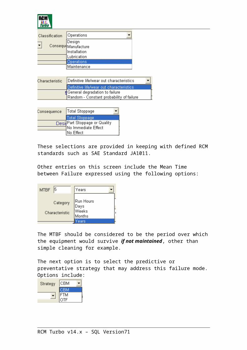
Within the main failure mode entry screen, there are a number of sub-screens that allow definition of the failure mode in RCM terms. Select from the drop down menus in each case:
These selections are provided in keeping with defined RCM standards such as SAE Standard JA1011.
RCM Turbo v14.x – SQL Version 51
Other entries on this screen include the Mean Time between Failure expressed using the following options:
The MTBF should be considered to be the period over which the equipment would survive if not maintained, other than simple cleaning for example.
The next option is to select the predictive or preventative strategy that may address this failure mode. Options include:
- where CBM is Condition Based Maintenance, FTM is Fixed Time Maintenance and OTF is Operate to Failure.
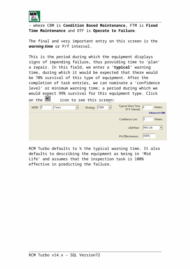
The final and very important entry on this screen is the warning time or P/f interval.
This is the period during which the equipment displays signs of impending failure, thus providing time to ‘plan’ a repair. In this field, we enter a ‘typical’ warning time, during which it would be expected that there would be 70% survival of this type of equipment. After the completion of task entries, we can nominate a ‘confidence level’ or minimum warning time; a period during which
we would expect 99% survival for this equipment type. Click on the icon to see this screen:
RCM Turbo defaults to ½ the typical warning time. It also defaults to describing the equipment as being in ‘Mid Life’ and assumes that the inspection task is 100% effective in predicting the failure.
RCM Turbo v14.x – SQL Version 52
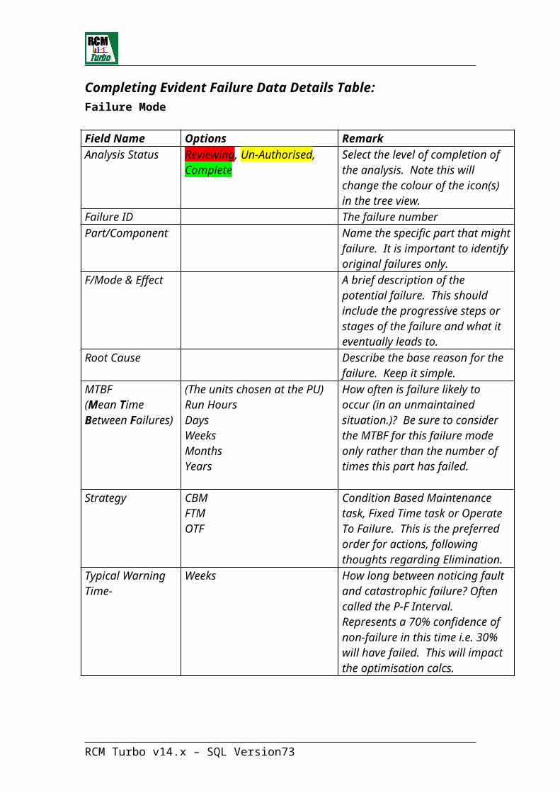
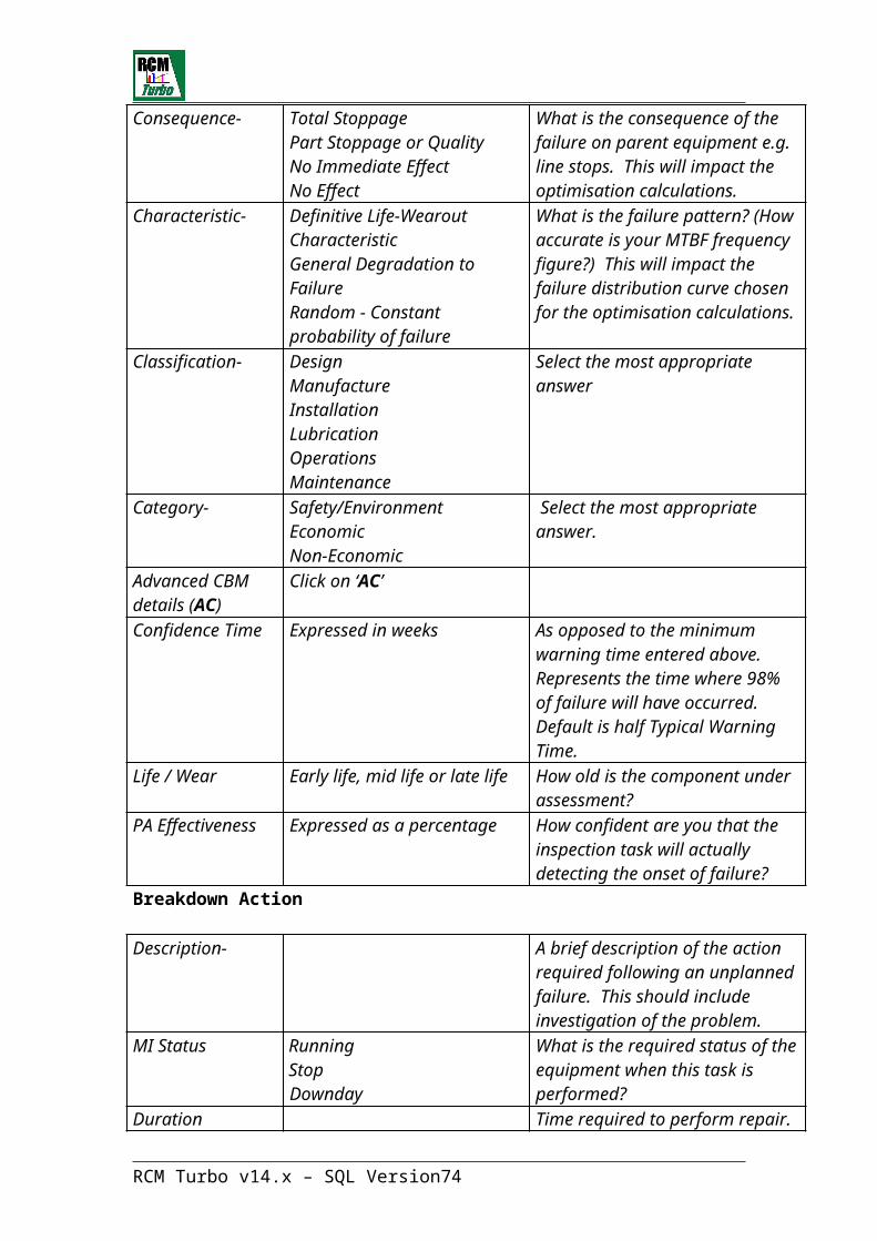
Completing Evident Failure Data Details Table:Failure Mode
Field Name Options RemarkAnalysis Status Reviewing, Un-Authorised,
CompleteSelect the level of completion of the analysis. Note this will change the colour of the icon(s) in the tree view.
Failure ID The failure number Part/Component Name the specific part that might
failure. It is important to identify original failures only.
F/Mode & Effect A brief description of the potential failure. This should include the progressive steps or stages of the failure and what it eventually leads to.
Root Cause Describe the base reason for the failure. Keep it simple.
MTBF(Mean Time Between Failures)
(The units chosen at the PU)Run HoursDaysWeeksMonthsYears
How often is failure likely to occur (in an unmaintained situation.)? Be sure to consider the MTBF for this failure mode only rather than the number of times this part has failed.
Strategy CBMFTMOTF
Condition Based Maintenance task, Fixed Time task or Operate To Failure. This is the preferred order for actions, following thoughts regarding Elimination.
Typical Warning Time-
Weeks How long between noticing fault and catastrophic failure? Often called the P-F Interval. Represents a 70% confidence of non-failure in this time i.e. 30% will have failed. This will impact the optimisation calcs.
Consequence- Total StoppagePart Stoppage or QualityNo Immediate EffectNo Effect
What is the consequence of the failure on parent equipment e.g. line stops. This will impact the optimisation calculations.
Characteristic- Definitive Life-Wearout CharacteristicGeneral Degradation to FailureRandom - Constant probability of failure
What is the failure pattern? (How accurate is your MTBF frequency figure?) This will impact the failure distribution curve chosen for the optimisation calculations.
RCM Turbo v14.x – SQL Version 53

Classification- DesignManufactureInstallationLubricationOperationsMaintenance
Select the most appropriate answer
Category- Safety/EnvironmentEconomicNon-Economic
Select the most appropriate answer.
Advanced CBM details (AC)
Click on ‘AC’
Confidence Time Expressed in weeks As opposed to the minimum warning time entered above. Represents the time where 98% of failure will have occurred. Default is half Typical Warning Time.
Life / Wear Early life, mid life or late life How old is the component under assessment?
PA Effectiveness Expressed as a percentage How confident are you that the inspection task will actually detecting the onset of failure?
Breakdown Action
Description- A brief description of the action required following an unplanned failure. This should include investigation of the problem.
MI Status RunningStopDownday
What is the required status of the equipment when this task is performed?
Duration Time required to perform repair.Downtime Expressed in hours Total time process was stopped
to perform repair.
Primary Action
Description- Options A brief description of the action required to predict impending failure.
Frequency- DaysWeeksMonthsYearsRun Hours
How often should task be conducted? Normally completed after optimisation. This field can be updated from the Group Optimisation and Update facility.
S/A Initiator What status would trigger a secondary action?
RCM Turbo v14.x – SQL Version 54

MI Status RunningStopDownday
What is the required status of the equipment when this task is performed?
Job Group Id- User Input Field to Group routine tasks into aggregated ‘check-lists’. This field can be entered and updated from the Group Optimisation and Update facility and via the Auto Grouping facility
Initiate Date- Defaults to date of Failure Mode entry. This field can be updated directly or via the Group Optimisation and Update facility.
Duration- Expressed in hours Elapsed time to complete individual task (hours). Note time for isolation etc. will be added at Group level.
Downtime
orD’time (PR)
Expressed in hours Time process was stopped in excess of what was allowed for in the business plan orSystem calculated downtime as (Pro-Rata) proportion of total time entered for Job Group (hours)
Secondary Action
Description- A brief description of the maintenance action required to delay failure or correct situation.
MI Status RunningStopDownday
What is the required status of the equipment when this task is performed?
Duration- Expressed in hours Elapsed time to complete taskDowntime- Expressed in hours Time process was stopped in
excess of what was allowed for in the business plan.
RCM Turbo v14.x – SQL Version 55

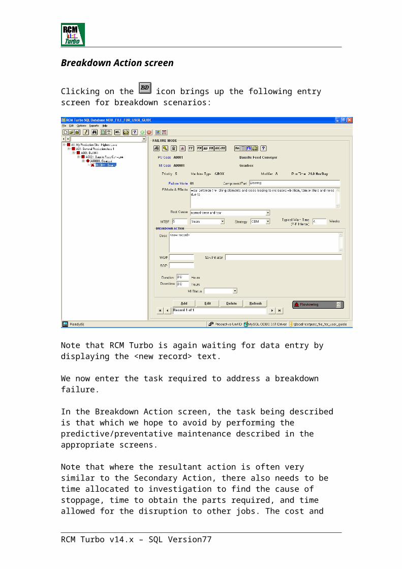
Breakdown Action screen
Clicking on the icon brings up the following entry screen for breakdown scenarios:
Note that RCM Turbo is again waiting for data entry by displaying the <new record> text.
We now enter the task required to address a breakdown failure.
In the Breakdown Action screen, the task being described is that which we hope to avoid by performing the predictive/preventative maintenance described in the appropriate screens.
Note that where the resultant action is often very similar to the Secondary Action, there also needs to be time allocated to investigation to find the cause of stoppage, time to obtain the parts required, and time allowed for the disruption to other jobs. The cost and duration of a repair performed under breakdown conditions can be 5 to 8 times more than the same planned repair.
Using the appropriate buttons at the top of the screen, users may enter both Resources and Spares required to complete this task.
There are several reasons for entering information in this part of the system.
RCM Turbo v14.x – SQL Version 56
Thinking about the effort and issues involved in overcoming an unexpected failure can increase the user’s understanding of that failure and its effects.
Where the frequency of performing the Primary Action is to be calculated using the RCM Turbo Frequency Optimisation facility, the data entered here will be used to build the cost model for the calculations. Also, having a detailed plan of how to overcome a failure can often speed up the repair in the event of such a failure.
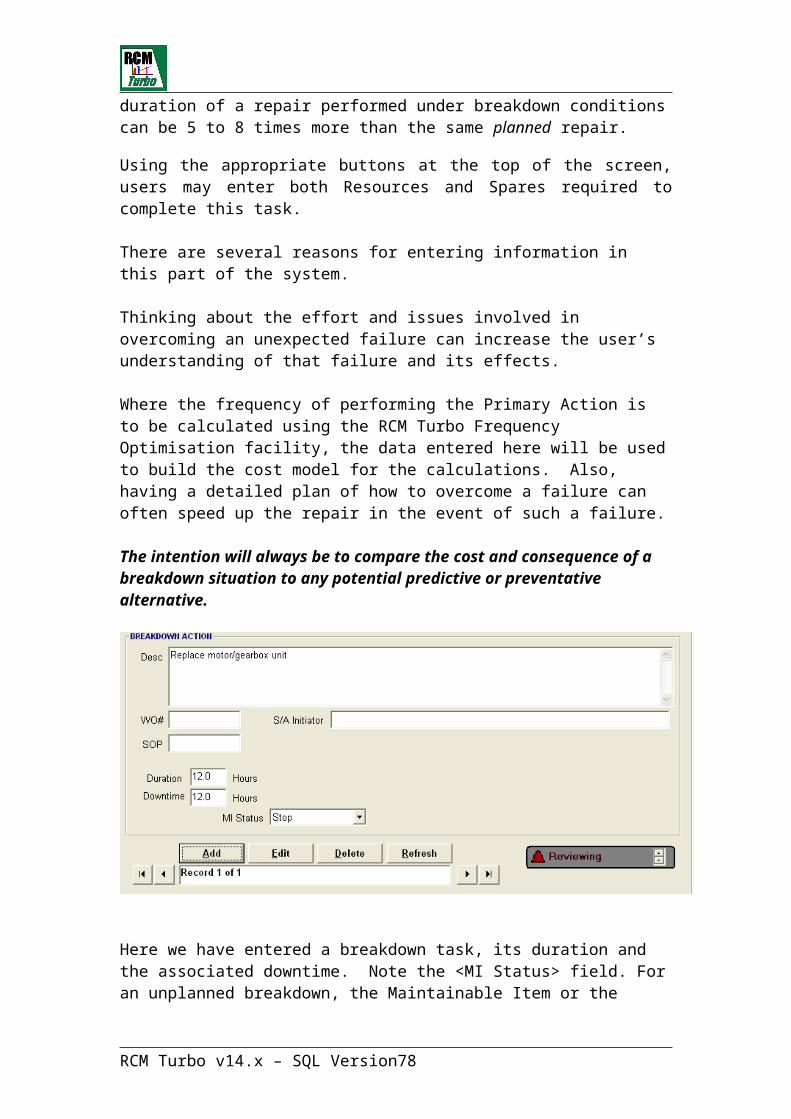
The intention will always be to compare the cost and consequence of a breakdown situation to any potential predictive or preventative alternative.
Here we have entered a breakdown task, its duration and the associated downtime. Note the <MI Status> field. For an unplanned breakdown, the Maintainable Item or the process will invariably be <STOPped>, while a planned repair will be <Down Day>.
A normal inspection task will normally be performed either while <Running> or on a <Down Day>. The importance of these entries is that they will bring forward downtime costs or otherwise as a result.
Click on <Apply> to save this record.
Now we can enter the details of resources required to perform this task by
clicking on the icon:
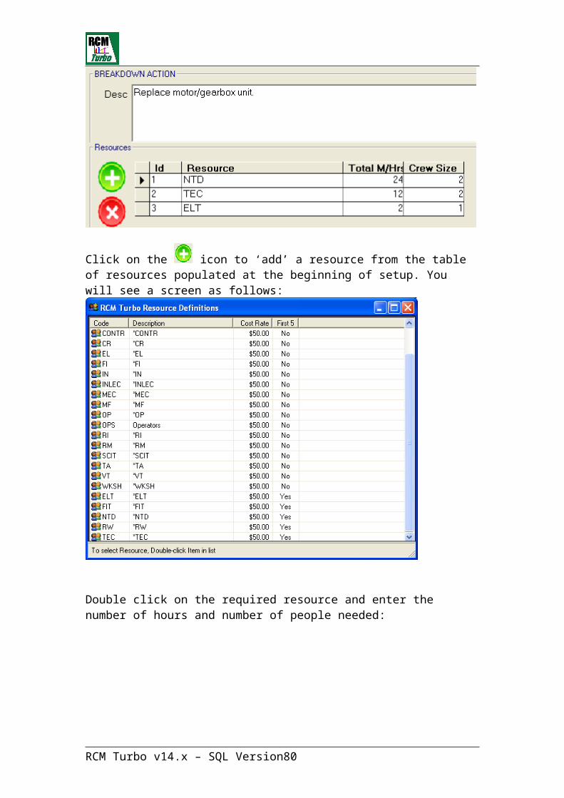
RCM Turbo v14.x – SQL Version 57

Click on the icon to ‘add’ a resource from the table of resources populated at the beginning of setup. You will see a screen as follows:
Double click on the required resource and enter the number of hours and number of people needed:
RCM Turbo v14.x – SQL Version 58
You can continue to add resources and man hours to complete this task.
Remember, resources can include items such as cranes that may attract a known hourly rate.
Here, we will add two more resources to the breakdown task:
We have now completed all required entries for a breakdown. Always click on
<Apply> to save. Click on the icon to return to the breakdown task screen.
RCM Turbo v14.x – SQL Version 59
Primary Action screen
We are now ready to enter the details of a Primary Task which may predict or
prevent this failure mode. To do this, click on the (Primary Action) icon.
The order for considering alternative actions is important to the degree of success of the whole analysis. Having first looked at options to eliminate the failure mode, the next step is to try to predict the impending failure usually via some form of condition monitoring (CBM).
If a suitable predictive action can be found this should be entered here. RCM Turbo will check the cost benefit of this action in the Frequency Optimisation process, so you only need to worry about the technical feasibility of the action at this stage.
All CBM actions have a Secondary Action (SA) to correct the problem prior to catastrophic failure. The trigger point for this secondary action must be entered in the S/A Initiator field.
Note that the job Duration for a Primary Action should not include time for travel or isolation of the equipment. This task is likely to become one of a group of tasks and it is the Job Group as a whole, which will have additional time allocated for travel and isolation, etc.
At this stage the duration should only cover the time that this task would add to a group of tasks. Note also that there are two fields, one for the time required to perform the task the other the time that the process will be affected.
There is also a drop-down to indicate the status of the process during this task.This is an important field when selecting ‘like’ tasks into groups as you would not want to have tasks which require the equipment to be stopped to be scheduled at the same time as tasks which require it to be running.
If a predictive action cannot be found, then the second preferred option is to try to prevent the failure.
The most common form of preventative action is to change out or adjust, etc on a fixed time basis (FTM). FTM is commonly selected where there exists a dominant failure mode for instance. An FTM action would not normally have a secondary action.
See below the Primary Action entry screen:
RCM Turbo v14.x – SQL Version 60

As before, Primary Action (Inspection) section is waiting for a new entry by displaying the <new record> text.
Note the entry of an ‘S/A Initiator’. This is intended to define what is being looked for or what condition would trigger a Secondary Action or planned repair. This may be a ‘level’ or may refer to external corporate documentation.
The other fields on this screen are awaiting the outcome of frequency optimisation and subsequent Job Grouping, initiate date, etc
Now we need to identify the resources required to perform this inspection. As
for the breakdown action, click on :
RCM Turbo v14.x – SQL Version 61
Use the ‘add’ and ‘remove’ icons as described in the breakdown section to add or remove resources and enter the total man-hours and crew sizes.
A condition- based Primary Action will always lead to a planned repair or Secondary Action. A fixed time task (FTM) or preventative task which is intended to replace the component before it fails will not have a secondary action.
For CBM tasks, we are now ready to enter the details of a planned repair or Secondary action:
Secondary Action screenWhere the primary action is looking for a condition as a trigger for doing some corrective action, a description of the corrective work required must be entered in the Secondary Action screen.
Here the time required for the job to be completed should include all travel and isolation etc as this task is likely to be scheduled individually although an attempt will no doubt be made to schedule other tasks at the same time.
The resources required can also be entered for the Secondary Action in the same way as described above for breakdown and primary actions.
RCM Turbo v14.x – SQL Version 62
RCM Turbo v14.x – SQL Version 63

Including Spare Parts in the analysisNow, for both the Breakdown Action and the Secondary Action, there is a need for a spare part, in this case a gearbox.
To identify and record this need, on all action screens there is a Spares icon
like this which opens the spares table if it has been pre-populated as recommended at the start.
The spares screen will default to ‘Maintainable Item Spares’ or bill of material information. If bill of materials information has not been entered, you can click on the ‘All Spares’ button to view any spare parts in the system. If no spares have been imported to RCM Turbo, then you will see a screen like this:
To add (say) a gearbox to the analysis, click on the icon in the main toolbar.
This will display the entry screen for spare parts as follows:
RCM Turbo v14.x – SQL Version 64
Click on Add to enter the required Gearbox.
Make sure that you use the correct spare code from your CMMS.
Again, you will now see the entry screen waiting for new entry:
RCM Turbo v14.x – SQL Version 65
RCM Turbo only needs the part number, part details and the part cost. Other fields here are normally used by SOS to optimise max/min levels.
Clicking on ‘Apply’ now displays these few entries and makes the spare available throughout the analysis:
RCM Turbo v14.x – SQL Version 66

Now you can use the back button to return to the entry screen for spares required as part of a breakdown (or other) action. Click on the ‘All Spares’ icon to view the newly entered spare(s):
To include this gearbox as a spare required to perform a breakdown task, ‘drag and drop’ it into the Description area above
:The gearbox and its cost will now form part of the task optimisation process.
You can also ‘drag and drop’ the spare onto a Maintainable Item in the main tree view, resulting in the addition of a spares folder on the tree (a Bill of Materials).
RCM Turbo v14.x – SQL Version 67
If you need more than one of any spare item selected for a task, just click on the spare in the upper pane. The spare now appears above and you can now nominate the number of spares required for the task.
Since this same gearbox would also be needed to perform a Secondary
Action or planned repair, follow this same process of clicking on icon and dragging and dropping the spare from within any Secondary Action screen.
On the action screens and others within the system, you will see the icon. Clicking on this opens a free text area which can be used to record assumptions and other notes that will be helpful to anyone reviewing the analysis at a later time.
Having now identified:
The failure modeIts consequencesIts characteristicsIts warning timesThe resources required to perform breakdown, primary and secondary actionsAny spares needed to complete any of these tasks
- We are now ready to establish whether the nominated tasks will be effective and if so, at what optimal frequency.
Before doing this, you will see that the failure mode under review is shown using an icon like this . The crossing out indicates that the failure mode has not yet been optimised for frequency.
RCM Turbo v14.x – SQL Version 68
Task Frequency OptimisationThe maintenance frequency optimisation facility will assist you to determine the optimum frequency for conducting frequency based maintenance actions; e.g.: for routine inspections, condition monitoring or fixed time change-out maintenance.
The purpose of conducting any sort of routine (preventive) maintenance is either to directly prevent a failure from occurring, or to measure some performance or condition based parameter to predict when a failure might occur - and thereby be able to take some preventive action before the failure actually occurs.
These routine actions have associated costs (the more frequently you do them the more it costs) and some associated benefits (the more frequently you do them, the less likely you are to have an unexpected failure).
Note the use of the words ‘less likely’ - conducting routine preventive maintenance does not guarantee the failure will always be detected and prevented - that depends on the frequency of the preventive maintenance, the failure mode characteristic and the probability of failure:
· If the failure is due to the wear-out of a component with a definitive and predictable wear-rate then the time at which the component is likely to fail can be estimated with reasonable accuracy. Probability of failure will be known and the required inspection frequency can be optimised to minimise total costs and the risk of failure actually occurring;
· If the failure pattern is random, then the conditional probability of failure is constant and no change in the frequency of routine maintenance will make any difference to that probability - unless there is an associated Warning Time (between detection of an imminent failure and actual failure) which is long enough to permit a corrective maintenance action to be performed before the failure occurs.
The optimisation of preventive maintenance frequencies is therefore dependent on four main input factors:
(a) The cost of doing the routine maintenance (job cost * frequency);(b) The cost of doing any planned repair work to prevent the onset of failure detected during the routine maintenance (job cost * frequency * probability);(c) The cost of repairing an actual failure (job cost * probability of failure), and;(d) The probability of failure / component life profile.
The cost of doing any of the maintenance jobs referred to above includes the cost of labour, the costs of materials, the costs of associated production
RCM Turbo v14.x – SQL Version 69

downtime, and in the case of an actual failure, the costs of any consequential damage.
The optimum frequency is calculated as the point at which the Total Cost is at a minimum in the equation:- Total Cost = (a) + (b) + (c) where, as (a) and (b) get higher due to increased frequency and probability of detection, and (c) becomes lower due to reduced probability of unplanned failure.
The various values of (a), (b) and (c) are calculated using probability equations of failure density functions contained within RCM Turbo for the component life characteristic selected.
A commonly utilised textbook graphic illustrates these principles:
RCM Turbo v14.x – SQL Version 70
Advanced CBM DetailsWhen the strategy selected is ‘CBM’ or condition based monitoring, an additional screen becomes available to refine the inputs. This screen appears when a ‘typical warning time’ of more than one week is input.
The system creates a “warning time” density function when you enter a warning time that is greater than 1 week. (For warning times less than 1 week the system ignores the input and assumes a long degradation time exists over the typical life for that particular failure mode)When you nominate a warning time greater than one week, an additional icon appears at the top of the failure mode screen:
Click on this to activate the Advanced CBM functionsYou will now see the following additional sub-screen:
The default settings when you enter a value A that is greater than 1 week are:
Typical Warning time = A weeks
Confidence Limit = A/2 weeks (Half Typical Warning time). This is the time when it is assumed that there is a 98% confidence of no-failures. All failures are assumed to have occurred after double the typical warning time.This relationship between Typical Warning Time and Confidence Time is user definable.
RCM Turbo v14.x – SQL Version 71
An additional feature, PA Effectiveness, defined as “the probability that the primary action will actually detect the onset of failure, once started”. The system setting is 100% but may be changed by the user for each failure mode.If you are not sure of the confidence, typical warning times or PA Effectiveness, then simply use the system default settings.
Life/WearThe final feature provided in the Advanced CBM section provides the user with the ability to monitor the cost effectiveness maintenance task over the life of the asset for specific failure modes. This feature allows you to explore the appropriateness of completing a CBM task at various times over an asset’s life. This is only relevant for age related failure modes, i.e. life characteristics described as “general degradation to failure or definitive life/wear characteristic”, because for the random failure pattern the conditional probability of failure remains constant over the life of the asset.The default setting is “Mid life” with “Early Life” and “End Life” also selectable. When you explore this feature you can determine whether specific tasks should be commenced immediately or at a particular time in the asset’s life.
To begin the task frequency optimisation routine in RCM Turbo, click on the
Icon from any screen relating to the target failure mode
RCM Turbo will now re-display all the information you have provided about the failure mode.
The first screen tab concerns the implications of a Breakdown Situation (or unplanned failure). This represents the scenario which is presumably to be avoided in favour of a predictive or preventative alternative:
RCM Turbo v14.x – SQL Version 72
Here, RCM Turbo notes that a breakdown may occur every five years in the absence of specific maintenance. It reports on the downtime, man-hours cost and materials cost associated with the breakdown in terms of the entries you made earlier.
In some breakdown circumstances, there will be additional ‘consequential damage’ costs (even fines for example). These should be entered here.The failure characteristics selected are displayed, as is the calculated cost of downtime along with failure consequence.
RCM Turbo will generate a five year analysis for the purpose of establishing an optimal frequency.
The alternative to this breakdown scenario is our newly entered condition based task which leads to a planned repair. Click on the ‘Predictive/Preventative Alternative’ tab to view this.
RCM Turbo v14.x – SQL Version 73
This screen displays both the Primary Task and the Secondary Action that the primary task will result in.
RCM Turbo has brought forward all the inputs made in previous screens.
Note the ‘Estimate Cost of Downtime from…’ field. The RCM Turbo default is to bring forward the cost of lost production from the parent Productive Unit. In the case of a task that is performed while running, the cost of lost production would be zero. In these cases, we select the ‘Alternate’ option in this field to embed a zero value.
For the Secondary Action (or planned repair), the same comments apply. A planned repair is normally performed on a down-day, which would not normally be regarded as a period during which there is a lost production cost.
Once we are satisfied will all these elements, a graphical display of the
optimal frequency can be obtained by again clicking on the icon.
RCM Turbo v14.x – SQL Version 74
RCM Turbo has now displayed a graph that shows the optimal frequency for performing the Primary Action. On the left axis is the total annualised cost, while the bottom axis represented the frequency in days. The solid horizontal green line represents the ‘operate to failure’ cost, which is constant over time.
Based on all the inputs so far, RCM Turbo recommends a frequency of 17 days for this task, at which interval reliability of 98% can be expected.
Preferred Frequency
Note the use of the 'Preferred' key on this display. When the system calculates an optimum frequency there is a strong possibility that it will be an inconvenient value. Most routine maintenance activities need to be combined into general check-lists which are done on easily managed time cycles, e.g.: weekly, monthly, quarterly, etc.
When the system recommends a specific number such as 37 days, remember this is the initial frequency information used for combining all the cost-effective tasks into job groups or schedules. It is recommended this frequency is accepted as your chosen frequency, because during the Auto Grouping process, the task will be combined with others at a suitable frequency. However if you want to round that off to a whole number of weeks, say 6 weeks (or 42 days), then click on the 'Preferred' button and RCM Turbo will allow you to input that preferred frequency. RCM Turbo will then
RCM Turbo v14.x – SQL Version 75

calculate the annual cost of maintenance associated with the preferred frequency. RCM Turbo will also re-calculate and display the associated new values of availability and reliability for your chosen frequency.
This process can be repeated as many times as necessary to arrive at the most suitable frequency and you will be able to see clearly the cost effect of not accepting the recommended minimum frequency.
Use of this button will take you back to the data screens.
This will allow the user to change any of the data on the two screens and recalculate the optimum frequency. In this way you can try a number of ‘what-if’ scenarios.
The data that defaults from previous screens, such as the downtime, man-hours and material costs, will continue to default. However all other values which have been entered directly to the optimisation data screen will be retained.
It is important to understand exactly how this works, particularly for the Downtime Cost information. Note that there is a separate Downtime Cost field for Breakdowns, Primary and Secondary actions. Each of these has the option to use the PU Downtime Cost, the MI Downtime Cost or an Alternate directly entered cost. Whichever of these is selected at the time of clicking the button, will be retained as the default source.
If users make no overrides, then they will only have to enter the information on the Productive Unit screen. This value will default into the MI Downtime Cost field on the Maintainable Item Screen. This happens at the time of generation of the Maintainable Item. Changes to the PU Downtime Cost will only flow through if this value is not changed at the MI level.
From the above it can be seen that the Breakdown Cost defaults from the PU Downtime Cost; the Primary Action Downtime Cost defaults from the MI Downtime Cost as does the Secondary Action Downtime Cost. Therefore, if the PU Downtime Cost is changed (and the MI Downtime Cost has not been over-ridden) the change will flow through to all the optimisation data fields. However if at any level this has been changed, then the flow on will be halted at that point. RCM Turbo training will highlight this functionality.
Following a possible number of iterations and ‘What if?’ calculations, it may be appropriate to enter some comments about the final model or range of models reviewed. This is best achieved via the Frequency Notes screen available from the frequency optimisation graph screen. (This free text screen is also available from each of the Action screens.)
Clicking the Update button will retain the additional data entered.
RCM Turbo v14.x – SQL Version 76
All optimisation data which was carried forward from the various Failure Mode and Action screen fields will always revert to the values entered in those fields.
If you have changed any of this data in the optimisation data screens (while performing What if? scenarios for instance) and wish to retain the changes, they will have to be manually changed in these previous screens also.
Clicking on the button will also write the Optimal Frequency in days to the Primary Action screen, so that the details will be ready for RCM Turbo’s Auto Grouping function to include the task and use its optimal frequency to combine it with other tasks on or about that frequency.
The button also updates the system to indicate that the failure mode has been optimised and changes the tree icon for the failure mode so that it is no longer crossed out.
When you have completed optimisation for all failure modes, the best way to develop work groups and task lists ready for the CMMS is to use RCM Turbo’s Auto Grouping function, described later in this Guide. It is possible to directly enter a frequency into the Primary Action screen but the Auto Grouping function will do this for you in a streamlined manner.
After the completion of failure modes and effect analysis, you may need to duplicate Maintainable Items and or failure modes in different locations. Please see the section in this guide which refers to duplication of data.
RCM Turbo v14.x – SQL Version 77
Completing Frequency Optimisation Details Table:
Breakdown Failure Data
Estimate MTBF if not maintained
DaysWeeksMonthsYears
How often does the failure occur? (Mean Time Between Failure)Defaults from Failure Mode screen
Estimate Repair Downtime for Failure
???? (Hours) An estimate of the down time if a breakdown occurs.Defaults from BD Action screen.
Estimate Repair Manhours cost
$???? This figure is calculated from the resources entered against the Breakdown Action and the Resource charge-out rate from the Resource Table
Estimate Repair Materials Cost
$???? Selected from drop-down listor $???? user input
The cost of the materials required to complete the task in a breakdown situation.Defaults from BD Maint Action Spares List screen.
Estimate Consequential Damage Cost
$???? Selected from drop-down listor $???? user input
An estimate of the cost of any consequential damage due to the breakdown.
Life Characteristic for MTBF
Definitive Life/wear out characteristics;General Degradation to Failure; Random (Constant Probability of Failure)
Relates to confidence failures will happen near MTBF i.e. select 'definitive' if approximately 70% of failures occur within +/- 25% of MTBF. Select 'general' if approximately 70% of failures occur within +/- 50% of MTBF and 'random' otherwiseDefaults from BD Action screen.
Estimate Cost of Downtime from....
$/Hour
Prod UnitMaint ItemAlternate
Default is Prod Unit. Users may choose which of the options will become the default. Prod Unit defaults from PU Screen; Maint Item defaults from MI screen; Alternate retains the user input value.
RCM Turbo v14.x – SQL Version 78
Equipment Failure Data
Consequence of Failure Mode
Total Stoppage;Partial Stoppage or Quality;No Immediate Effect;No Effect.
What is the consequence of this failure mode i.e. complete line stops, reduction in output or no loss. Defaults from Failure Mode screen
Equipment Maintenance Analysis Life
5 Years - ???? Default is 5 years but can be changed for individual reviews if required. (0 years is not permitted)
Primary Action Data
Estimate CBM/FTM Action Downtime
Hours An estimate of the downtime required to perform the Maintenance Inspection task? Defaults from Primary Action screen.
Estimate CBM/FTM Action Manhours cost
$???? This figure is calculated from the resources entered against the Primary Action and the Resource charge-out rate from the Resource Table.Defaults from Primary Action screen.
Estimate CBM Action Materials Cost
$???? Selected from drop-down listor$???? user input
The cost of any materials required for the task.Defaults from Primary Maint Action Spares List screen.
Estimate Consequential Damage or other Cost
$???? Selected from drop-down listor $???? user input
An estimate of the cost of any consequential damage or any other costs incurred due to Inspection Action
Estimate Detect/Repair Warning Time
Weeks How long between noticing/detecting a fault and having to fix it? Defaults from Failure Mode screen.
Estimate Cost of Downtime from....
$/Hour
Prod UnitMaint ItemAlternate
Default is Maint Item. Users may choose which of the options will become the default. Prod Unit defaults from PU Screen; Maint Item defaults from MI screen; Alternate retains the user input value.
RCM Turbo v14.x – SQL Version 79
Secondary Action Data
Estimate Planned Repair Downtime
Hours An estimate of the equipment downtime required to complete the planned repair. Defaults from Secondary Action screen.
Estimate Planned Repair Manhours cost
$???? This figure is calculated from the resources entered against the Breakdown Action and the Resource charge-out rate from the Resource Table. Defaults from Secondary Action Resources screen.
Estimate Planned Repair Materials Cost
$???? Selected from drop-down listor $???? user input
The cost of any materials required to perform the repair?Defaults from Primary Maint Action Spares List screen.
Estimate Consequential Damage or other Cost
$???? Selected from drop-down listor $???? user input
An estimate of the cost of any consequential damage or any other costs incurred due to Inspection Action
Estimate Cost of Downtime from....
$/Hour
Prod UnitMaint ItemAlternate
Default is Maint Item. Users may choose which of the options will become the default. Prod Unit defaults from PU Screen; Maint Item defaults from MI screen; Alternate retains the user-input value.
This process of performing failure modes and effects analysis should then continue against all the target equipment. At that point, there will be an accumulation of information, some of which needs to find its way into your Computerised Maintenance Management System.
Specifically, this will be task and frequency information. RCM Turbo accommodates this in a number of ways. Please see Auto Grouping later in this manual and also CMMS interface details
RCM Turbo v14.x – SQL Version 80

Entering Failure Mode Information - Hidden Failures
A Hidden Failure is one where the failure does not become evident to the operator under normal operating circumstances. There must always be a second, concurrent failure for a Hidden Failure to become Evident or for the failure to have an effect. Note that this second failure must be an independent failure, not a consequential failure occurring as a result of the first.
A classic situation to illustrate this is one where there is a protecting system that is incapable of providing that protection. For example an overload device that has failed in an unsafe way (perhaps it will not open when required). It is not until the equipment goes into overload (i.e. outside its normal operating conditions) that the original failure become evident or even becomes a problem. For the equipment to go into overload a second, independent failure must occur at the same time.
Hidden Failures can be entered as follows. Use the right mouse button to add a new Hidden Failure Mode:
RCM Turbo v14.x – SQL Version 81

HIDDEN FAILURE MODE SCREEN
In almost all cases of Hidden Failures, the most appropriate way to reduce the risk of catastrophic failure is to test the operation of the protecting system on a regular basis.
It is important to find a task which tests the full system as far is possible and not just that part of the system that most often fails. It is not unusual to find that a broken connection somewhere in the circuit would have stopped the system from functioning as designed.
This is the entry screen for a Hidden Failure mode. The system defaults to an area for entering information about the potentially failing component or device. TABS are provided for additional information required about the Protected Unit, the testing task and the resources that are required to conduct the fault finding task to be established. Other TABS allow entry of any assumptions made regarding the Hidden Failure and also any relevant Notes.
We can now enter some detail on the failing component and its MTBF:
RCM Turbo v14.x – SQL Version 82
Click on the ‘Apply’ button after each entry screen is completed.
Now, we complete the Protected Unit details:
Note that RCM Turbo will not have made any calculations at this stage. The outcome from a Hidden Failure assessment is a fault finding interval, which is a calculation based on the MTBF’s of both the protecting and protected units, as applied to the acceptance of risk of dual failure – as follows:
RCM Turbo v14.x – SQL Version 83
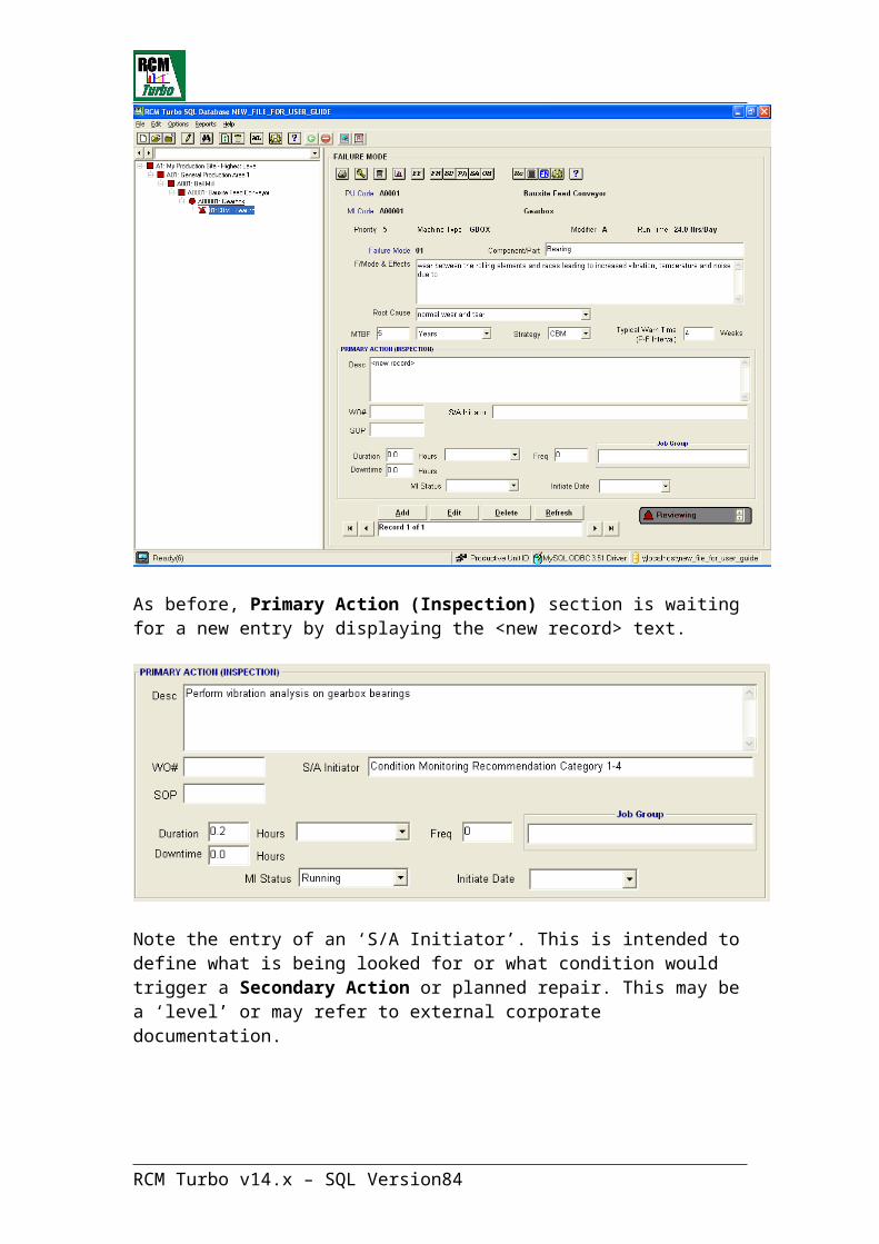
Here, we have entered a risk acceptance of 1 in 100. Clicking on the Apply button saves the record:
Now we click on the icon to view the recommended Fault Finding interval and to display the MTBF for both the protecting and protected units:
The outcome from this calculation is a recommended fault finding interval of 182 days. Click on Apply to save this record.
This will enter the Fault Finding Interval into the frequency fields on the Task Details screen so that the Autogrouping function can include the task in workgroups that will eventually be formed.
Now we need to identify and record the resources to perform this task:
RCM Turbo v14.x – SQL Version 84

Click on the Resources tab. Now click on the Add Resources icon to add resources:
After selecting the ‘ELT’ resource and nominating the crew size and hours, we see the following screen:
These labour hours and resources will now also become available for workflow analysis and eventual generation of task lists etc for the CMMS.
An important element in Hidden Failure assessment is that of risk assessment.
RCM Turbo v14.x – SQL Version 85
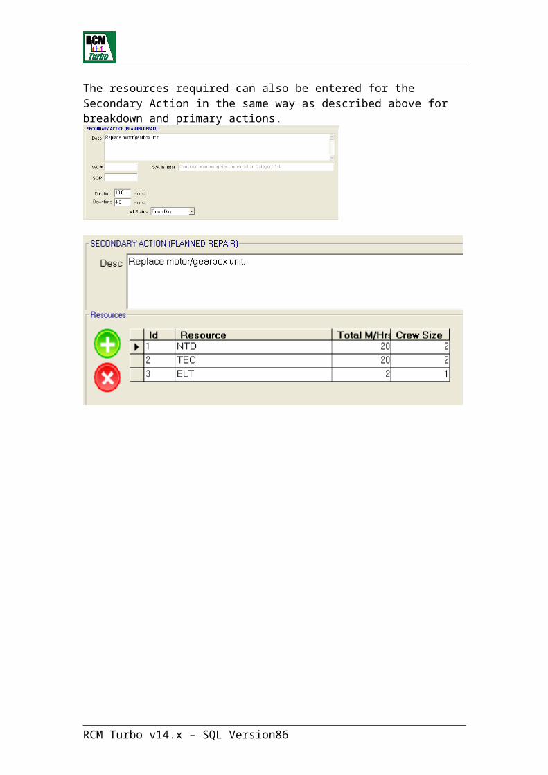
Organisations should develop their own matrix of levels of acceptable risk based on the severity of the failure and the degree of risk aversion of the company. An example matrix is shown below.
Risk Assessment for Hidden Failures
Typical Consequence of Multiple Failures
Acceptable Risk
(per year)
Event Description
Safety Environment Cost of Failure
Lost Production
1 in 100,000
Major Incident
Multiple serious injuries- including likely death
Greater than $10,000,000
Greater than 50 days
1 in 10,000 Prolonged public outcry threatening continuation of business.
Less than $10,000,000 but greater than $1,000,000
Less than 50 days but greater than 5 days.
1 in 1,000 Very serious incident
Serious injury leading to permanent disability.
Major license breach with possible prosecution.
Less than 5 days but greater than 0.5 days.
1 in 100 Serious incident
Lost time injury
Minor license breach
Less than $100,000 but greater than $10,000
Less than 0.5 days.
1 in 10 Minor incident
Minor Less than $10,000
Minor loss of production.
Having now completed both Evident failure modes & effects analysis and hidden failure Fault Finding Interval assessments, we are now ready to create workflow information ready for the CMMS.
RCM Turbo v14.x – SQL Version 86
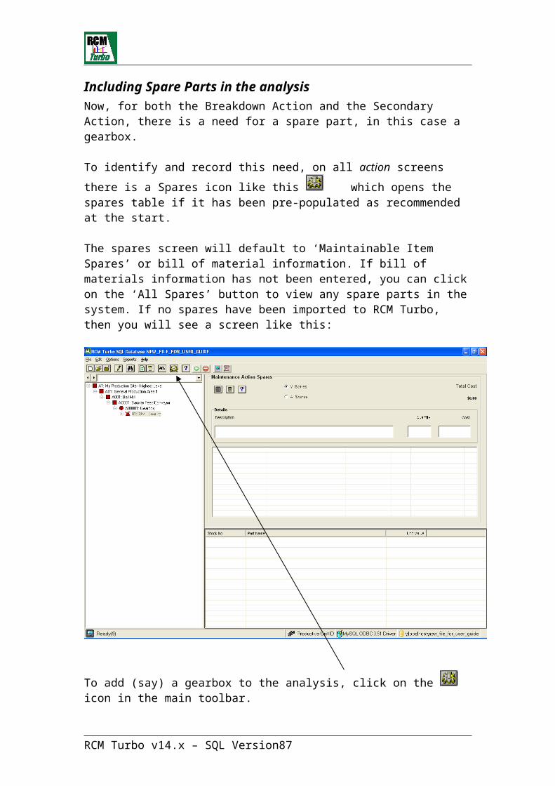
Auto-Grouping Facility
Auto-Grouping Overview
Before discussing the operation of the Auto Grouping function within RCM Turbo, it is worth covering the way that tasks and their frequencies have been recorded up to the point of forming workgroups.
For each evident failure mode, you will have established an optimal frequency as described earlier in this Guide. The final step in optimising each failure
mode is clicking on the Update button on the optimisation screen. This has the effect of telling the system that the failure mode optimisation is complete and replaces the un-optimised display as follows:
with a view that looks like this
.
In normal usage, you will not have utilised the ‘Preferred Frequency’ function up to this point. This function is best utilised when groups have already been formed and there is a need to see what the annualised cost and reliability implications are of including a specific task within a group that may not match its original frequency interval.
The button also updates the task frequency on the Primary Action screen with the optimal frequency. This value is used by Auto Grouping to find tasks that meet user defined frequency ranges with a view to eventually putting all such tasks into convenient frequency groups.
Auto Grouping is a very powerful facility within the system. Its primary function is to assist and automate the process of grouping suitable tasks together. However, it can also be used to model various shutdown scenarios and obtain the total cost to an organisation. From this it will be possible to find the lowest cost option. For instance, it may be more cost effective to have frequent shut-downs of short duration rather than less frequent but of greater duration.
The Auto-Grouping Selection Screen is used to indicate which set of Primary Action tasks are to be included in this review and how they are to be displayed on the workflow Cluster Graph screen.
The next step will be to review the graphical display of the tasks. From this it should become clear as to the frequencies around which the tasks are clustered as well as the sort of resource and time load in those clusters. This will provide guidance for next step of setting the groups across each cluster of activities as required. From this, the total and shortest times, along with the resource requirements, by resource type, will be displayed for each group. If you are satisfied you may set these groups into the main database. You may
RCM Turbo v14.x – SQL Version 87

try alternative groupings until you are happy with the result before submitting them to the main database.
Since the generation of workgroups is by definition a ‘what if?’ concept, RCM Turbo has internal tables specifically relating to Auto Grouping. These are regenerated each time you begin a new scenario. If you complete a scenario and ‘update’ a job group, then the Primary Action screens for each failure mode in the group will remain updated with the chosen group details, until such time as you choose to over-write them with an alternative group scenario.
Auto-Grouping – selection screen
To access the Auto-Grouping facility, click on the Work-Load button on the Toolbar. Next select Auto Grouping from the menu as displayed below.
This will display the Auto-Grouping Selection screen. At this point, we will populate the demonstration file with a more complete failure modes and effects analysis so that meaningful data can be shown. See Merging Data for a description of this process:
RCM Turbo v14.x – SQL Version 88
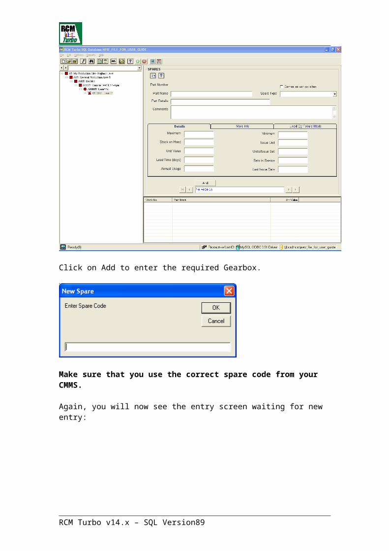
We can now click on “Select all PU’s” or whichever productive units we need workgroups for. Similarly, we can narrow down the selection to specific Maintainable Items within a PU, or “Select All MI’s”
Probably the first selection to be made on this screen is the MI Status option. Are you looking just for those tasks that require the equipment to be running, or are you looking to establish shut-down requirements, for instance?
Next select the equipment under review. Are you just looking at a single piece of equipment, or perhaps the whole file or any combination of these?
Note that if you select an individual Productive Unit (PU), you may then select individual or multiple Maintainable Items (MI) within that PU. Simply click on the line item to select an individual, or use the Ctrl key to select additional lines, or the Shift key to select all items between two lines. This facility also works in the PU list to select multiple items. If you select more than one PU you will automatically get all MI’s within those PU’s.
To change from a restricted selection to the full database, simply click the “Select all PU’s” button.
Next decide whether you wish to include those tasks which have already been assigned to Job Groups within the main database. If you include these tasks, when you come to Update the database, any existing task numbers will be over-written.
There are two other selections that you may make.
RCM Turbo v14.x – SQL Version 89

It is possible to limited your group to contain only (or more) Resource Types.
It is also possible to create groups for work that are either CBM or FTM or both.
Finally select how you wish the data to be displayed on the Cluster Graph screen. In cases where only a small amount of data is to be included in the display, it may be best to set these options to the lowest settings, i.e., unit = weeks (or even days), range = 1. However, where the quantity of data is large or the difference between the lowest and highest frequency is great, a larger unit or range per cluster may be better. It is probably a good idea to experiment with this until the display best illustrates the required information.
The default display is “Months” starting from zero in a range of Three Months.
The first step is to create ‘clusters’ of work by first defining what unit of measure (days, weeks, months etc) we wish to start with, in this case, Days and in clusters of 1 week. We might do this because we wish to establish what tasks need to be performed weekly or every fourteen days say. Beyond that point, we can probably look at monthly scenarios:
Now, to view a ‘cluster’ graph of work that meets this criterion, click on the graph symbol:
A screen such as this will display:
RCM Turbo v14.x – SQL Version 90

This screen displays the Cluster Analysis Graph based on the choices made in the Selection screen.
Each point on the graph represents an individual cluster, made up of all the Primary Action Tasks that fall into the range of the frequency shown on the horizontal axis. It can therefore be seen that the Range selection made in the Selection screen has a considerable effect on the size of each cluster.
You can see that there is a task or tasks way out at beyond 7000 days (or 20 years).
There are three axes on the graph:
1. The horizontal axis represents frequency in the chosen units-of-measure.
2. The left-hand vertical axis represents the total number of both resource and duration hours required for each cluster.
3. The right-hand vertical axis represents the quantity of Primary Action Tasks included in each cluster at its indicated frequency.
There are three sets of data displayed for each point or cluster.
1. The total of all Primary Action Durations for each cluster.
2. The total of all Resources required for each cluster.
3. The quantity or number of Primary Actions included in each cluster.
RCM Turbo v14.x – SQL Version 91

You have a great deal of control over the graphical display on this screen.
1. You may zoom into any part of the graph by clicking and holding the left mouse button and dragging a box over the area required to be zoomed. You may zoom again by repeating the above action even within a zoomed view. To return to the original view, use the right mouse button and click Un-Zoom.
2. You may print the current view (zoomed or un-zoomed). Use the right mouse button and choose the Export Dialog option. From here choose to Export to Printer. It is advisable to use the Customisation Dialog option before printing the graph to enter an appropriate Main and/or Sub-Title to the graph. You may directly access the Export facility from the Customisation Dialog screen.
3. Change other display options. Use the right mouse button and choose those options you wish to change. For further information, choose the Help facility on this menu.
Once satisfied with the display, we can move on to automatically generating some work groups based on frequency ranges (and access to equipment as determined in the original cluster selection).
Create Groups Screen
To access the Create Groups screen, click on the Group button on the Toolbar.
This screen is used to create Job Groups based on the clusters and units of frequency (Days/Months/Years etc) displayed in the Cluster Graphic screen:
To create a Job Group, enter the Group ID or code by clicking on the icon. This is a free format naming convention (eg W01). Now you can enter the
RCM Turbo v14.x – SQL Version 92

low and high limit for this Group. The next step for each new group is to click
on the icon which displays the graphic below.
Here we are looking to group tasks optimised to occur between 1 and 14 days:
Note that the range selected includes the lower value but excludes the upper value, i.e. the range 1 to 14 will include all PA’s with a frequency of 1 through to 13.99, but will not include those with a frequency of 14.
The Calculate button is used to calculate the total hours for each resource plus the Total of Task Durations. Also displayed will be the total Number of Tasks in the Group and Longest individual Task Duration. The Resource information will be displayed in a histogram on the right side of the screen.
When you are satisfied with the content of a Group generated, you click on
the (Update) button.
The effect of clicking on the (Update) button is that the newly defined Workgroup name is written to the Primary Action screen for each failure mode
addressed within that Group. The other effect of clicking on is that the name of this newly formed Group will now be included in the panel showing “Group Names already applied to FM’s”
Continue to add new Groups within the same frequency unit
(Days/Months/Years etc) by clicking on and enter the details of the next Job Group. Repeat this until all Groups in this set have been entered.
RCM Turbo v14.x – SQL Version 93
Calculator Button
To view the resource and other details for each Job Group, select that Group from the list.
Note the importance of the selection on the Auto Grouping Selection screen which asks whether or not you want to include tasks that are already in a Group.
In this selection we are creating a monthly task group call W1M. We have chosen tasks optimised to occur between 1 and 2 Months. Note the existence of our W14D Group in the “Group Names already applied to FM’s” list:
We now continue to create Groups in Months:
RCM Turbo v14.x – SQL Version 94

RCM Turbo v14.x – SQL Version 95
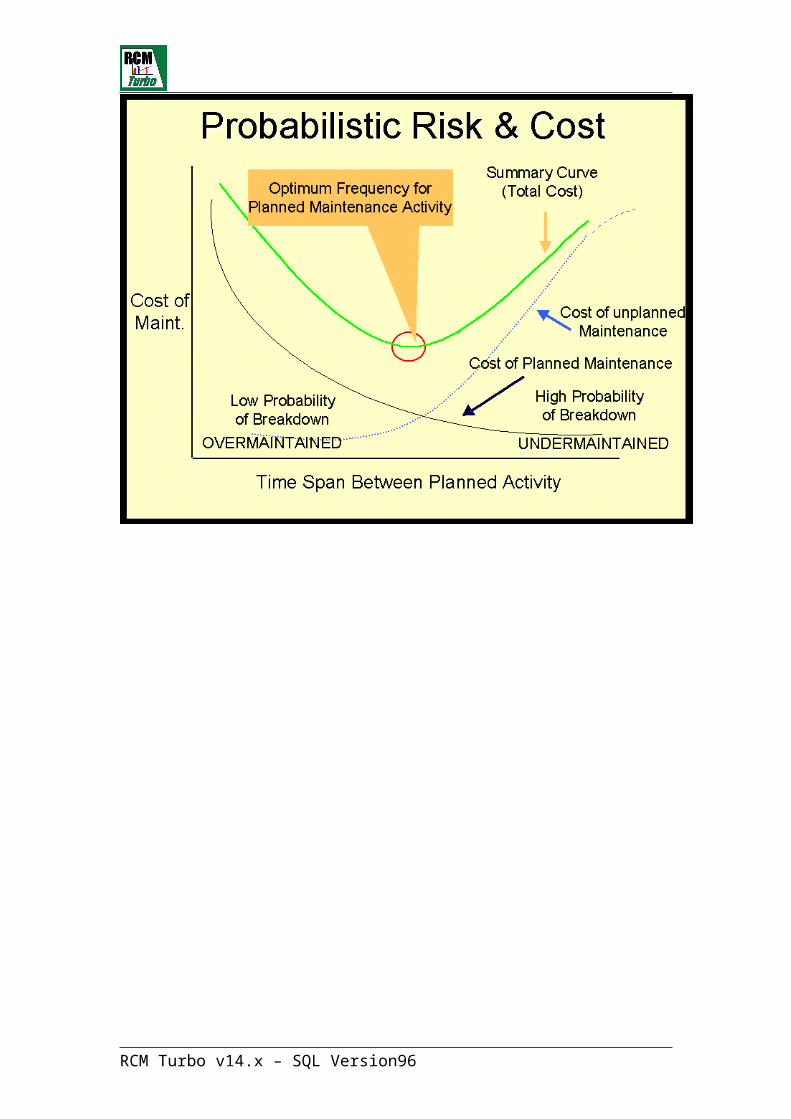
You may make changes to the Job Groups as required, returning to the Cluster Graph screen for clarification or even changing the data selection in the Selection Screen if required. The Job Group data entered here will be retained until you exit the Auto-Grouping facility, or until you change the data.
Again, when editing groups that you have already generated, make sure you select “Include PA’s already included in Job Groups” from the Autogrouping selection data screen.
Once you are satisfied with the Job Groups entered, you may use the ‘Update Job Groups’ button to apply the Job Group ID’s to all the Primary Actions included in each Group.
We are now ready to Optimise/Update Grouped Actions with a view to generating Job Group Actions Lists and providing additional data to individual Failure Mode Primary Action screens. This data may include Standard Operating Procedures, Work Order Numbers and any other CMMS related fields that may appear as a result of your choice of CMMS interface.
RCM Turbo v14.x – SQL Version 96
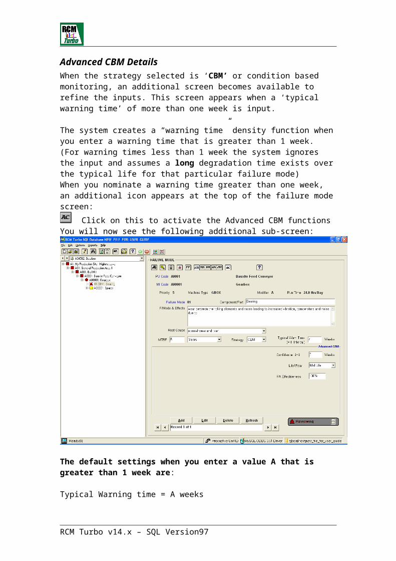
Optimise/Update Grouped Actions
Click on Optimise/Update Grouped Actions from the WL screen:
You will see the following entry screen:
RCM Turbo v14.x – SQL Version 97

GROUP FREQUENCY Optimisation FUNCTION
Grouping of Tasks
The overall maintenance frequency optimisation facility will assist you to determine the optimum frequency for conducting any number of frequency based maintenance actions for a single maintainable item or for maintenance actions grouped by Job Group ID’s. This facility is particularly useful where limited access is available in continuous type operations or where significant “re-start” considerations exist.
Clicking the drop down list and looking at an Auto-Generated Group W05, we see the following screen:
These represent the tasks that matched our input for tasks that were optimised to be performed at intervals between 10 and 14 Months.
Note that the duration of Primary Tasks is displayed on this screen as is downtime (if any).
To quickly establish what the optimal frequency for this Group would be:
Select the 'Graph' button to display the overall optimum frequency graphic for the grouped actions.
RCM Turbo v14.x – SQL Version 98
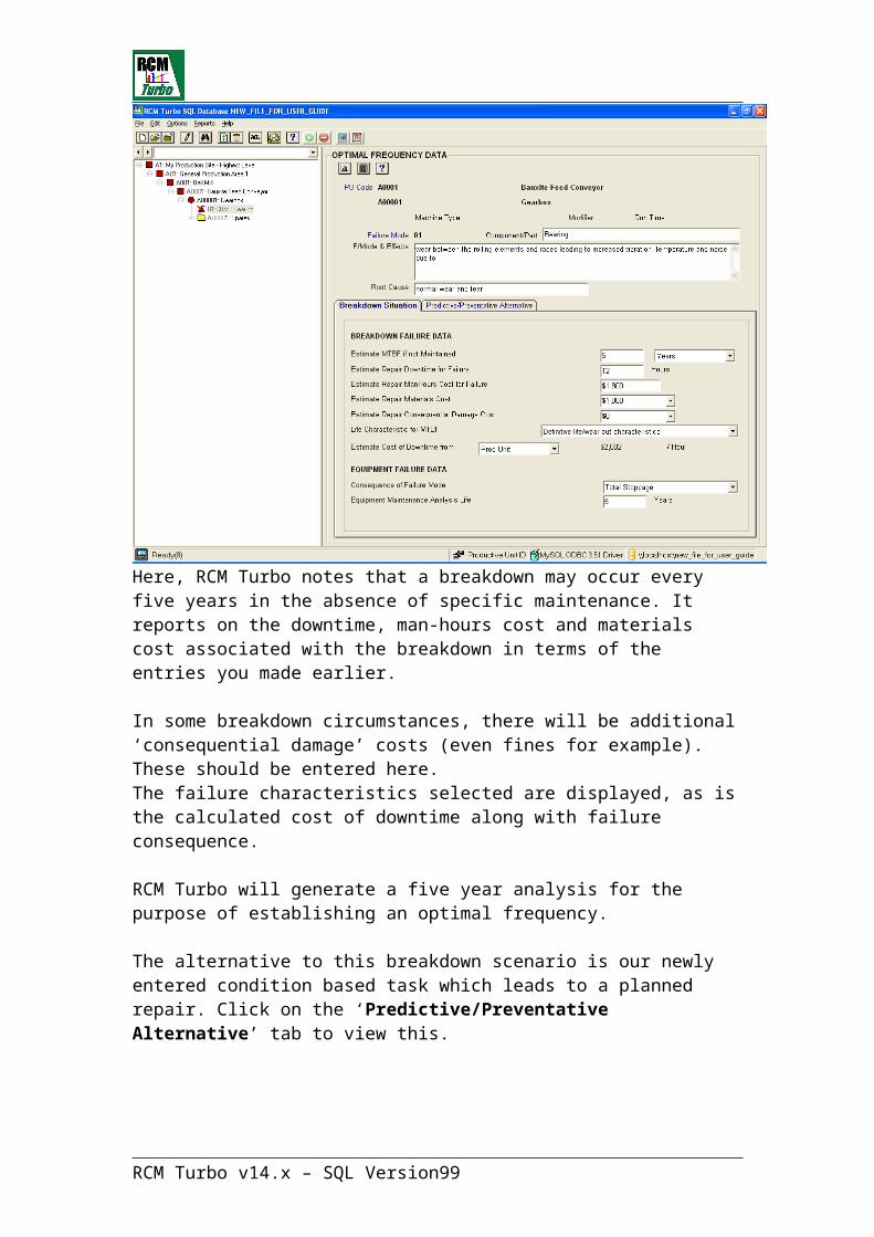
This graphic is telling us that the optimal group frequency is around 365 days (or 12 months).
The overall group optimisation screen displays the average curve for all the Primary Actions as listed in the current Job Group. RCM Turbo calculates the optimum frequency for the group and displays both the frequency in days and the annual cost.
Users may enter their preferred frequency and RCM Turbo will show the position on the graph, plus the annual cost of performing the maintenance at that frequency. An example of this is shown below.
The Preferred Frequency Button may be used to enter the preferred frequency for comparison with the optimum frequency.
The Update Button is used to save the results of the calculation and exit the graph screen.
The Exit Button is used to exit the graph screen without update. In this case any preferred frequency will be forgotten.
RCM Turbo v14.x – SQL Version 99
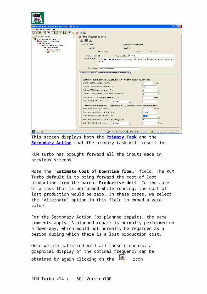
Here, we can see that optimal frequency for another Group is around 72 days. We have entered a preferred frequency of 90 days to determine the impact on annualised cost.
RCM Turbo v14.x – SQL Version 100

It may be that the tasks we have selected in a Group are more suited to an alternative frequency (say 7 Days). We could reflect this in the next step, which is the final “Updating” of a job group.
Now, if satisfied with the Group, we can ‘Update Job Groups’ by clicking on the icon to see the following screen:
Here, you can provide a full text ‘name’ for the Group and enter a frequency that represents the local view of how tasks should be grouped. Your entry here will replace whatever frequency was entered on the Primary Action screen as a result of earlier optimisation of the task frequency and updating it at that point.
An ‘Initiate Date’ can also be entered from this screen. A drop down calendar is provided to facilitate this.
A ‘Work Order’ and ‘Standard Operating Procedure’ numbers can be updated onto each individual Failure Mode’s Primary Action within the Group. Each record will be updated at the same time on clicking the ‘Update’ button. Depending on your CMMS definition for interface purposes, additional fields may appear here for update. These might include “Plan No” or “Task List No” in the SAP environment for instance.
The Total Duration field shown on the above screen is intended to reflect the duration of the whole group of actions. This figure holds some additional significance in RCM Turbo. Based on the calculation in this field, RCM Turbo
RCM Turbo v14.x – SQL Version 101
updates the Primary Action Duration for each Failure Mode on a Pro-Rata basis.
We will now complete this screen to generate an Annual task list and update all records associated with the newly formed Group:
Clicking on Done completes the update.
It is important to realise that this will have an effect on the individual Primary Action’s frequency, which may in turn change the overall Group’s optimum frequency. For this reason it is suggested the Group Optimisation Facility is approached in the following order.
1. Select each Failure Mode in turn and update its individual Optimum Frequency.
2. Group activities by Access requirements, Job type and approximate frequency, etc.
3. Select Group to be optimised and enter Title and Total Duration for group.
4. Use Update button to apply this data to each Primary Action.
5. Use Optimise button to update each individual frequency optimisation, taking into account the pro-rated duration.
6. Use ‘Done’ button to exit Update window.
RCM Turbo v14.x – SQL Version 102

7. Run overall Group Optimisation to find average optimum frequency.
8. Return to Update Group facility and update Frequency and Initiate Date as required.
Whenever you return to the ‘Optimise/Update Grouped Actions’ screen, you will see the completed data for existing groups, in this case the newly updated ‘Annual Task List’:
Looking at this list, you can view the original optimised frequency along with the now established frequency at which the tasks will be performed within a Group.
There will be occasions where tasks may fall into a Group which renders their frequency ineffective. See the following Group (W6M) for an example of this:
RCM Turbo v14.x – SQL Version 103

Note this failure mode. Its optimal frequency is 146 days, yet we may be including it in a group where other tasks are less frequent. It is here that we will make use of the Preferred Frequency function available at failure mode level.
From the Job Group Actions List screen, we can click on the failure mode in question and move to its optimisation screen:
RCM Turbo v14.x – SQL Version 104
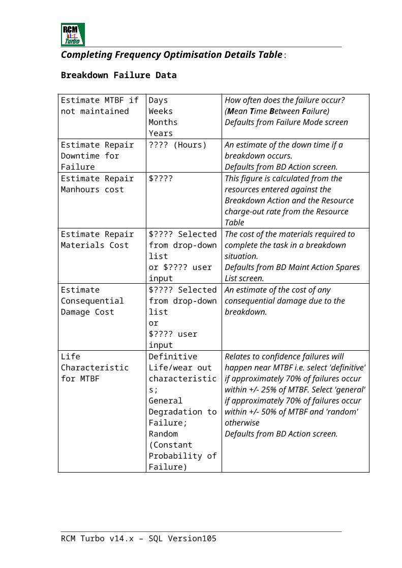
We will now click on the Preferred Frequency icon to see what it would mean to perform this task on a three monthly basis:
RCM Turbo v14.x – SQL Version 105

From this display, we can see that the probability of failure curve is very insensitive at and around this interval. There is only a minor difference in annualised cost and reliability. On this basis it will be perfectly acceptable to include this task within the Three Monthly inspection group.
By using the icon, we can move back to the Job Group Actions List and continue the process of formalising this Group.
Click update to complete.
RCM Turbo v14.x – SQL Version 106

Now the Job Group Actions list for the Six Weekly Task List looks like this:
- and if you looked at any of the Primary Action screens for these failure modes, you would see that the frequency has changed from whatever it was to “6 Months”.
Ungrouping of Tasks
In the course of performing ‘what if?’ scenarios using Auto Grouping, you may need to undo groups so that you can begin again.
The 'Ungroup Tasks' icon allows the user to select the number of tasks from the group they wish to ungroup. You can select the whole list using the “Select All Items” button at the bottom of the list screen or just individual failure modes.
Utilisation of this facility will return the frequency of the individual tasks to their original 'optimised' frequency.
You may still open an individual failure mode primary action screen and individually remove the group code. While this will remove the task from the group, the frequency for the selected primary action will remain unchanged.
Now that we have a Task List that suits our purposes, we can now ‘re-order’ the tasks in sequence number using the up or down arrows as below:
RCM Turbo v14.x – SQL Version 107
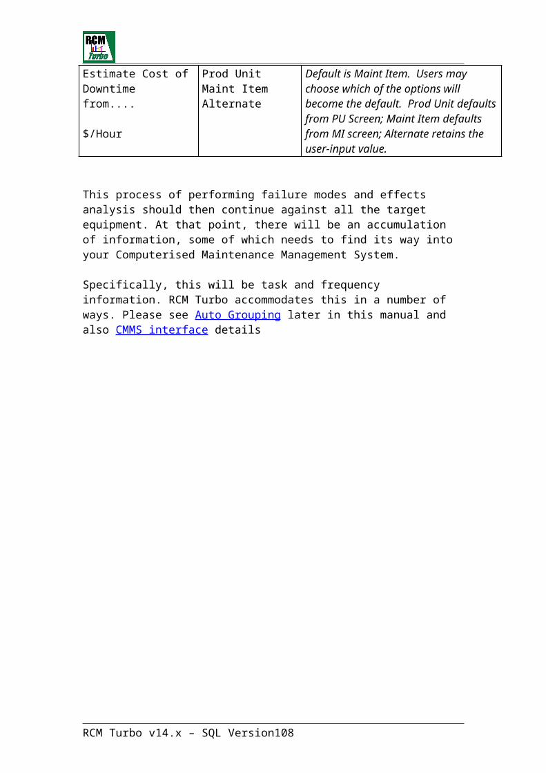
Just highlight a task, then use the up or down arrow to move the task up or down the list. This action will re-order the tasks.
RCM Turbo v14.x – SQL Version 108

Workload ForecastingThe Workload Forecasting facility will assist you to plan the execution of the actions you have identified for the plant.
Note: Data can be displayed and updated in the Workload Forecasting facility and all changes are reflected throughout the RCM Turbo database. This allows for quick iterative changes when data requires manipulating.
To run the RCM Turbo Workload Forecasting facility click on the Workload icon.
Select from the Workload Forecast (WL) menu to generate the forward workload file. This function generates a file containing the extrapolated failure data over a period specified by the user. A screen as shown below will be displayed. Simply enter the start and finish dates and indicate if you wish to include secondary actions, then the file will be generated.
Note: The Repair (or Secondary) Action MTBF Factor defaults to 1.0 but may be changed to suit the particular plant. The purpose of this feature is as follows. In an attempt to give some indication of the likely resource requirements for Secondary Actions (Repair work or ‘jobs arising’), it has been assumed that such action will occur at about the frequency actual failures would have occurred; i.e. at MTBF. Hence the default value of 1.0. However, for new plant or where there is confidence the preventive maintenance is extending the time between Secondary Actions, this factor can be increased up to a maximum of double MTBF.
Here, we have selected a range of dates from 18/10/2007 through to 18/06/2008. A useful ‘calendar display is provided to facilitate these kinds of date selection:
RCM Turbo v14.x – SQL Version 109
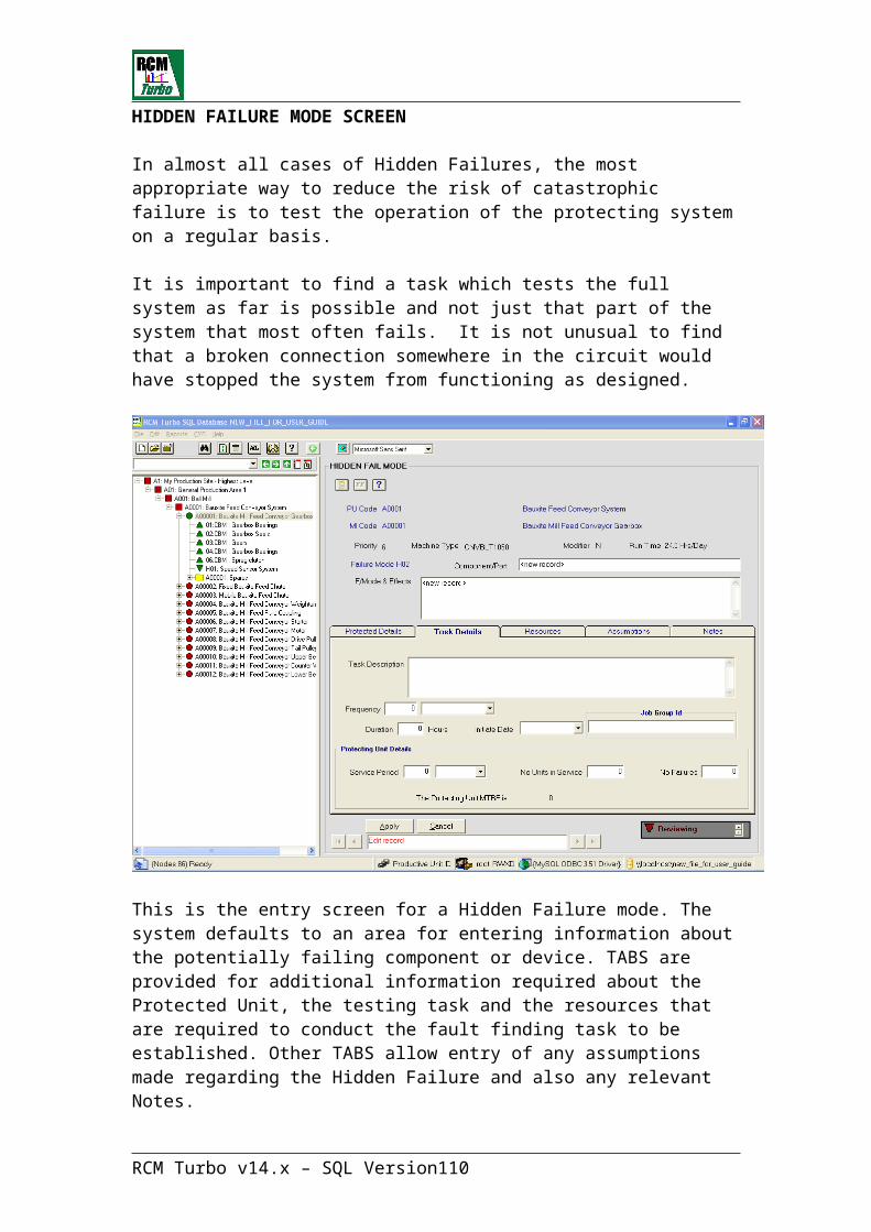
Clicking on OK here will produce the information needed to generate a Resource Requirements Histogram.
It is possible that RCM Turbo will report errors in the generation of Forward Workload. In this event, you will see a message such as this:
The error report will be displayed on the screen, so that you can fix any issues if required by clicking on the offending failure modes.
RCM Turbo v14.x – SQL Version 110
In this case, RCM Turbo is reporting that a particular Hidden Failure mode is included in the analysis but does not yet have a valid ‘Initiate Date’.
You can click on the offending failure mode directly from this error list.
From the Forward Workflow file the resource requirements histogram can be displayed, relevant reports can be printed and the workload manipulated as required.
Work Requirements Histogram
Select the 'Work Requirements Histogram' option from the Workload Forecast menu to display the resource requirements histogram of the forward workload file as shown below.
The Histogram may reveal periods during which there is a need for more of a particular resource than may be available.
To establish what jobs are causing a peak in the workload in any particular period, it is necessary to produce the 'Period Job Analysis'. This is a useful way to "smooth” the forward workload and match the new optimised schedules to actual, available resources.
From the general ‘Reports menu’, select ‘Workload’ to display the workload reports menu as shown below.
RCM Turbo v14.x – SQL Version 111
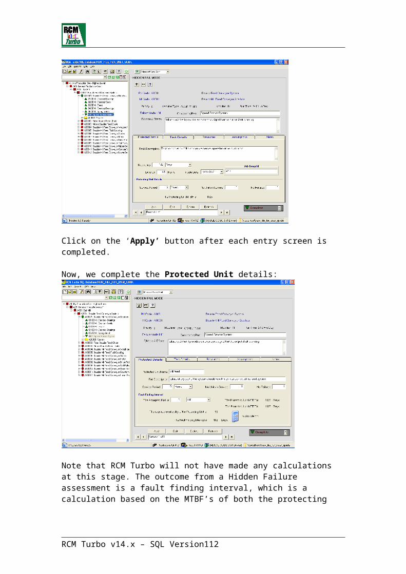
Note that the Forward Workflow file must be recreated each time to take account of any changes made to the data before running any of these reports. To do this, click on ‘Generate Forward Workflow’ from the WL menu.
RCM Turbo v14.x – SQL Version 112
Changing Initiate Dates
You may have entered an initiate date when generating Groups and subsequent Job Group Actions lists.
It is also possible to globally change initiate dates for tasks at Productive Unit and Maintainable Item levels.
To do this, click on the WL icon, then select: “Change Initiate Dates by Productive Unit or Maintainable Item”:
Make your selections from the dropdown lists to write new Initiate Dates to each failure mode Primary Action screen:
RCM Turbo v14.x – SQL Version 113
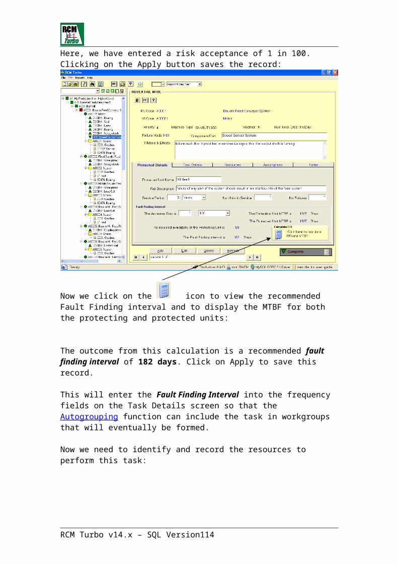
Auto-Grouping – Selection Screen Fields Table:
Select All PU’s Click this area to change your selection from a single PU to all PU’s. Notes if no selection has been made, the default is All PU’s.
Prod Unit Select individual or multiple PU’s. You may scroll up and down the list using the scroll bar to the right of the list.
Maint Item This list is only filled when an individual PU has been selected. Select individual or multiple MI’s as required. The default is All MI’s.
Include PA’s which already belong to a Group Y/N
Select either Yes or No depending on whether or not, you wish to include those Primary Action Tasks that have previously been allocated a Job Group number.
Access Select Running, Stopped or Down Day, individually or in combination.
Unit of Measure Choose between Days, Weeks, Months or Years. This will designate the horizontal axis for the Cluster Graph display.
Start Point Set the start point for the Cluster Graph. Default zero.
Range The number of units the software will add together for each point on the Cluster Graph.
RCM Turbo v14.x – SQL Version 114

Reporting within RCM Turbo
Click on ‘Reports’ on the main toolbar to view the selection possibilities.
There are many report options available in RCM Turbo. Many of them have been identified previously in this manual. All reports are available via the Reports Menu.
The Annualised Preventative Maintenance Budget Report is a particularly powerful output. Following the detailed analysis of a process plant and development of a full Preventative Maintenance Plan, this report can be considered a Zero Based Budget report for that plant. It provides both Resource and Material costs for each Productive Unit, with a summary total.
It provides this information separately for Primary (Inspection) and Secondary (Planned Corrective) and OTF (Breakdown) maintenance actions as well as a combined total. Zonal Inspections and Hidden Failure tasks are included.
NOTE: You must enter an Initiate Date for each record or the task costs will not appear on the Budget report.
RCM Turbo v14.x – SQL Version 115
General Navigation and Functions in RCM TurboIn RCM Turbo, the right mouse button is a primary navigation tool for adding, deleting and otherwise modifying data.
A ‘History’ function exists in RCM Turbo which allows users to re-trace where they have been in the equipment hierarchy. Clicking on any element will take you to that location:
A ‘back’ and ‘forward’ function is also included (these work in the same way as your familiar web browser for instance).
These icons allow you to fully open the equipment hierarchy and also to fully close the hierarchy.
Close Open
RCM Turbo v14.x – SQL Version 116
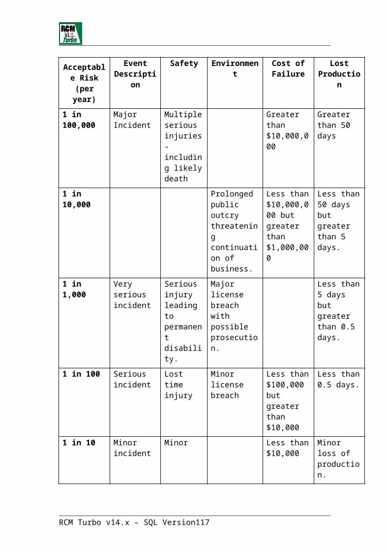
In most RCM Turbo screens, data entered will only be saved after clicking on the ‘Apply’ button.
At any time, user may ‘refresh’ the display of equipment hierarchy. This may be useful during the development of equipment hierarchy information.
Generally, RCM Turbo automatically refreshes data after clicking on the ‘Apply’ button.
A ‘Search’ function is provided. This can be used to locate any data within the RCM Turbo file including Productive Units, Maintainable Items, Failure Modes and Spare Parts.
This function is most effective where the * key is used before and after the required expression as follows:
In RCM Turbo, the equipment hierarchy is ALWAYS visible in the left pane. Clicking on any element will take you to the selected data entry screens.
RCM Turbo v14.x – SQL Version 117

Copying, Pasting, Dragging & DroppingIn RCM Turbo, you can duplicate information in a number of ways.
Using the right mouse button, you can select both ‘copy’ and ‘paste’. The target items can be duplicated in another location by highlighting the new location and clicking on paste.
You can also highlight more than one item by using the traditional ‘control’ or ‘shift’ keys for multiple items. Highlighted items can be ‘dragged and dropped’ to a new location in the hierarchy.
The traditional Windows functions of CTRL/C and CTRL/V also work in RCM Turbo.
Where a Maintainable Item and its associated Failure Mode analysis is to be duplicated within the same Productive Unit, RCM Turbo will retain all the MI and FM details included optimisation outcomes.
Where a Maintainable Item and its associated Failure Mode analysis is copied to another different Productive Unit, then the failure mode and task data is copied but the optimisation outcomes are dumped. This is because in the new operating environment, there will be different downtime costs, consequential damage costs and other elements that will not necessarily be the same as those in the original operating context.
RCM Turbo v14.x – SQL Version 118
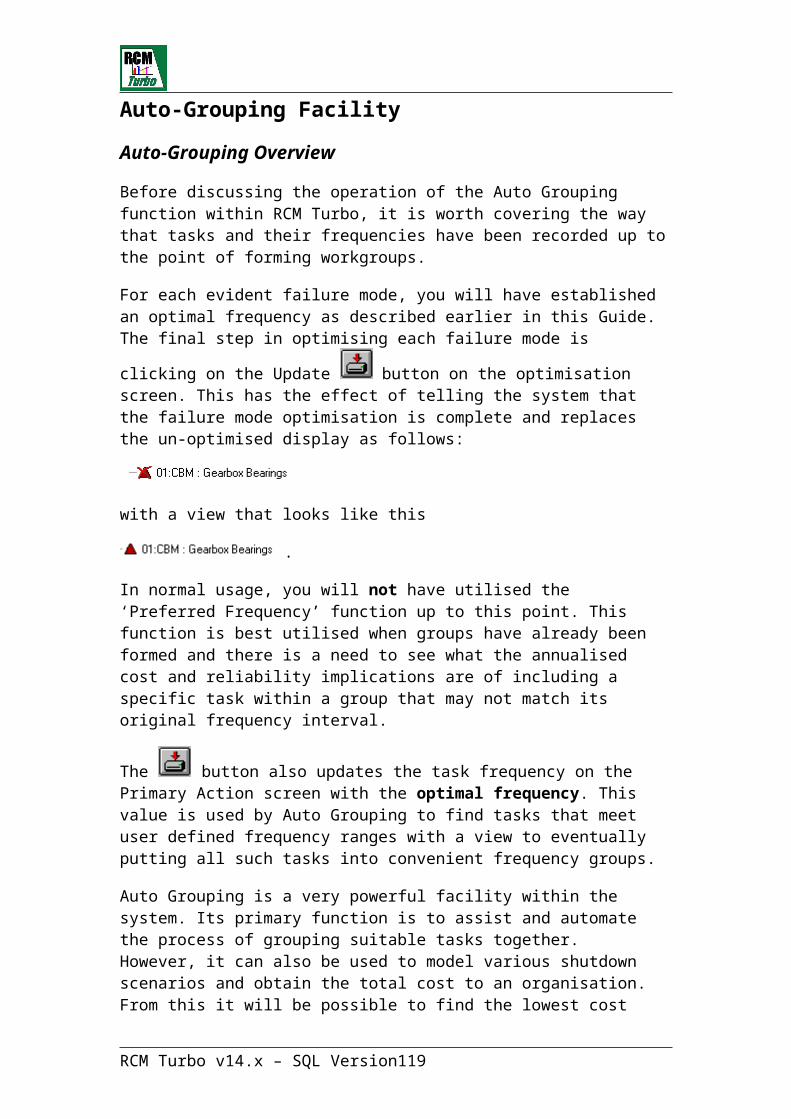
Optional General Display SettingsUsers are able to dictate how RCM Turbo appears on the screen.
To change the colour of all screen backgrounds, click on this icon:
To change the font type of RCM Turbo displays, click on this dropdown:
RCM Turbo v14.x – SQL Version 119

Merging Files within RCM TurboOn the main RCM Turbo screen, prior to opening an existing file, there is a toolbar selection for ‘Merging’ RCM Turbo data files.
This function is accessed by clicking on
Merging of RCM Turbo files is a required function where multiple assessors have generated their separate data files. This may have arisen for logistic reasons such as a decision to work on Electrical based issues versus Mechanical or for any other reason.
Each user site will eventually require an RCM Turbo ‘Master’ file, which is likely to be used for the accumulation of all site data with a view to producing the workflow information needed by the local CMMS.
Merging involves identifying the file to be merged ‘from’ and the file to be merged ‘to’. Using the merge icon as described above produces the following screen:
- where the default display is the most recently used RCM Turbo file.
From the Database drop down menu, select the database you wish to merge data from. The next screen will look like this:
Clicking on OK will copy all the data from the first file into the target file.
RCM Turbo v14.x – SQL Version 120
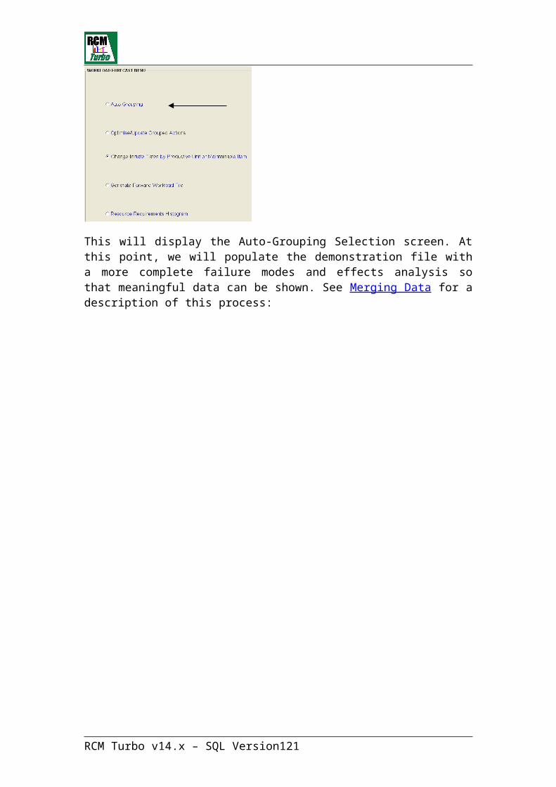
Languages Other than English
RCM Turbo is capable of being translated into any Windows supported language.
After you install RCM Turbo, there will be a directory created called ‘Language’. This will be a subdirectory in the format of:
C:\Documents and Settings\User Name\Application Data\Strategic Corporate Assessment Systems\Language
Using Windows Vista, the Application Data directory is called ‘Apps’ and may be hidden by default.
In this directory is each of the files used by RCM Turbo to allow either English or the target language. The name of each MDA file will clearly show the language. If your language of choice is not included, simply make a copy of one of the files and rename it to your desired language. These files can be accessed through Microsoft Access.
There are a series of tables within each file that display “English” and “Other”, where “Other” can be the language indicated by the file name.
To translate to another language, the translator should be familiar with English and the target language, particularly in the area of technical language and expressions that might be used by maintenance and engineering people.
The translator should access each table in the file and simply replace the current entry in the “Other” record with the target language or correct errors and omissions in the language file chosen.
These tables include field names, error messages and all other facilities that would appear in the English version of RCM Turbo. Ignore the ‘Resource Table’.
When all translations have been made, the system is ready to be run in the target language. Run RCM Turbo and make the language selection prior to opening any file.
User can now select the alternative language instead of English by clicking on the dropdown list displayed. This list will contain any language files that may be available including the one you have just translated.
RCM Turbo v14.x – SQL Version 121
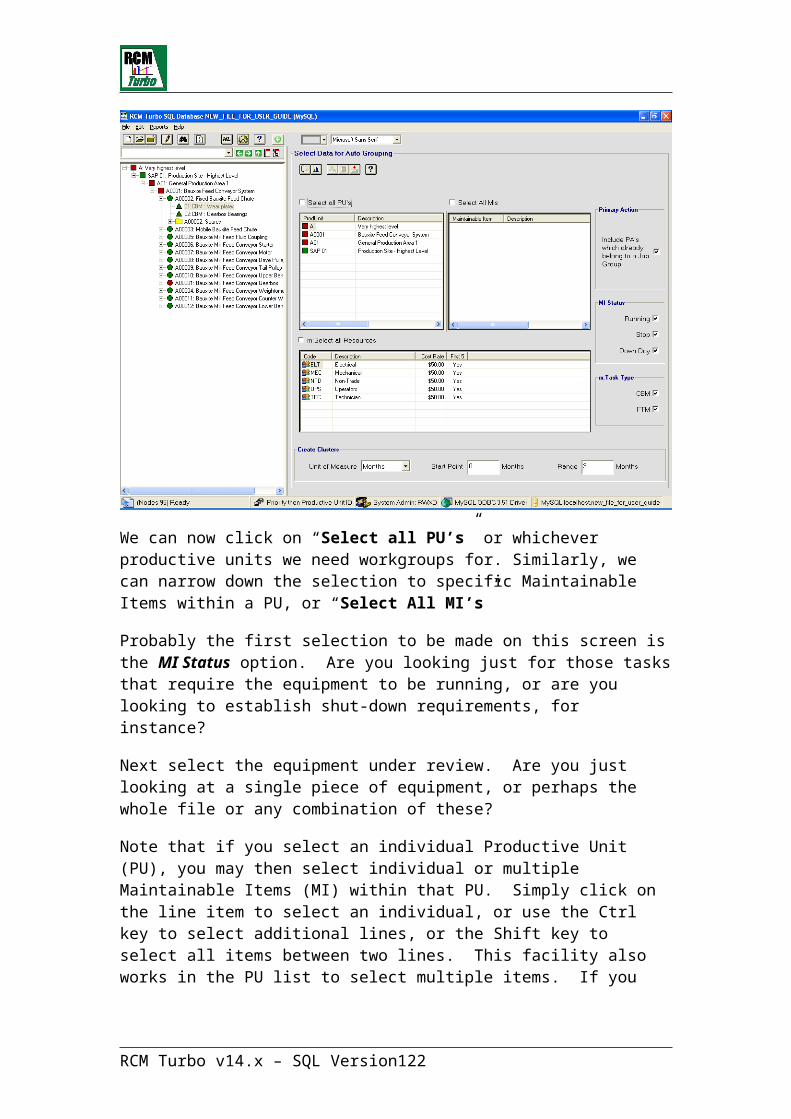
Should it be the case that after performing translations, certain fields are still appearing in English, but preceded by e: or m:, then run RCM Turbo with a special ‘Captions’ switch so that any such fields will be written to your language file. Such a command line will look like this (use your path to the Program):
"C:\Program Files\RcmtSQL V14\RcmtSQL.exe" -captions
If you wish to complete the translation of any existing ‘other’ language, just open the target file in that same location using Access and make the necessary changes or additions. These changes will then reflect in RCM Turbo for the chosen language.
It is recommended that you advise Strategic if you have completed any translations. The target language file should then be emailed to Strategic so that any changes will be retained for future releases.
RCM Turbo v14.x – SQL Version 122

Other CMMS Data Transfers
RCM Turbo v14.x – SQL Version 123
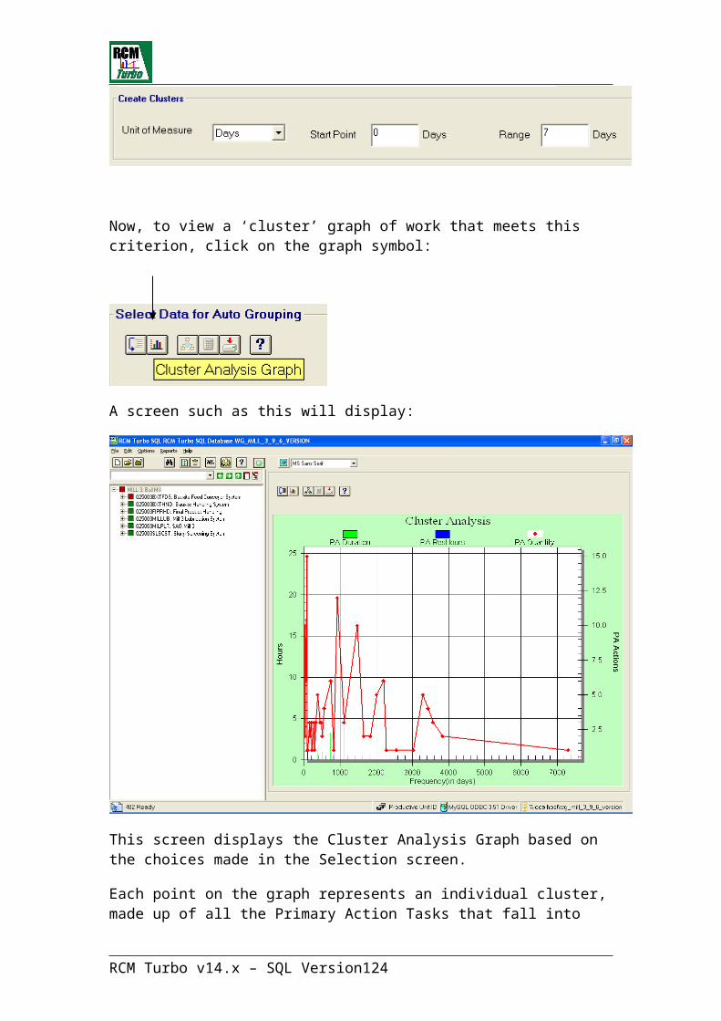
SAP CMMS Data Transfers
RCM Turbo v14.x – SQL Version 124

Import of Data
Included in the installation is an Excel add-in sheet called <RCMT and SOS SQL Data Import Template.xla>. You will find this add-in under the Programs directory in the RCM Turbo SQL Group. To activate the add-in, use Microsoft Excel TOOLS/ADD IN’S to include the xla in your standard installation of Excel.
This sheet is used to populate RCM Turbo with initial data which can include:
Productive Unit informationMaintainable Item informationSpares information Maintainable Item Spares (Bill of Materials) information.
The data for these tables will have been extracted from your current CMMS or other systems. The fields shown in RED are needed specifically by RCM Turbo.
The spreadsheet will take this data and populate a nominated RCM Turbo SQL data file.
Click on the ‘Create Workbook’ icon to setup the sheet for use.
If required, click on to view comments about each field
RCM Turbo v14.x – SQL Version 125
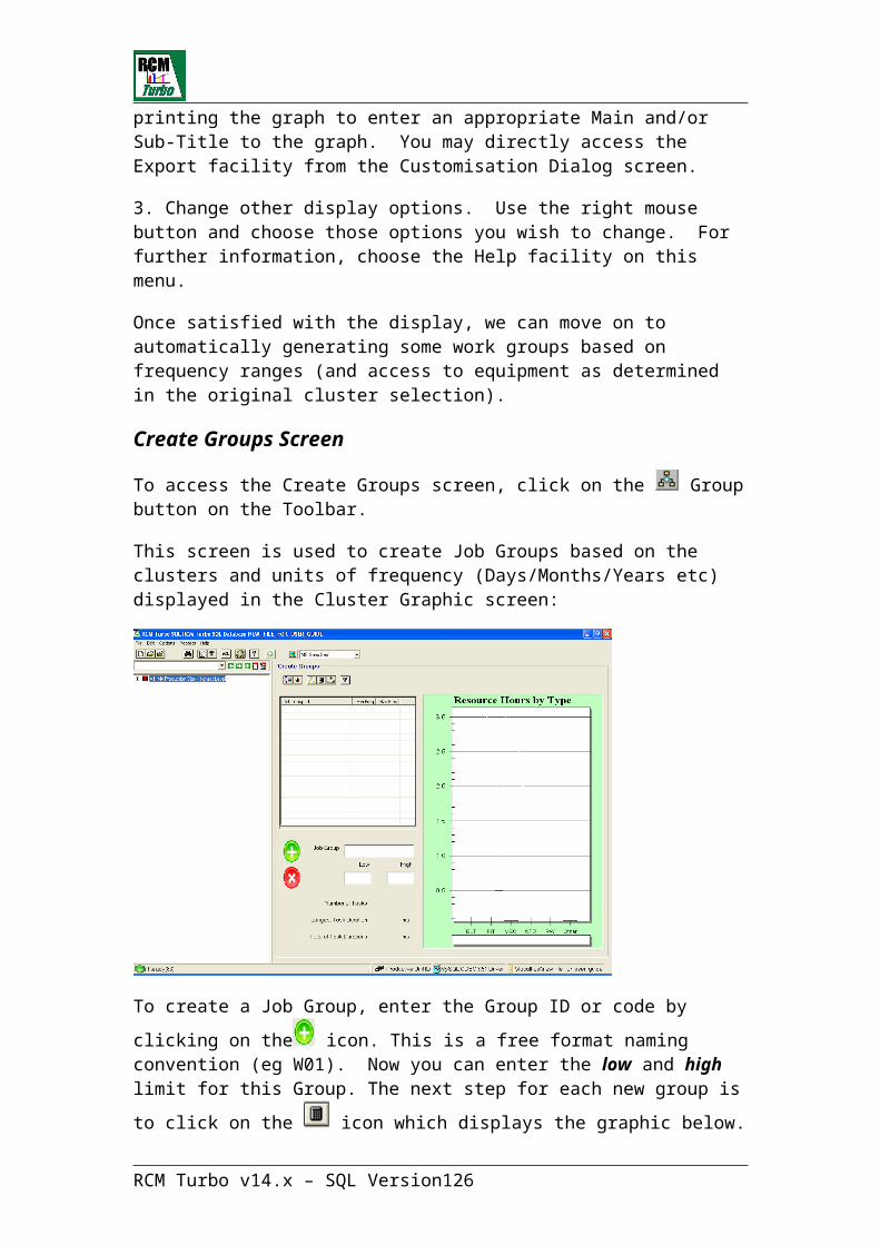
Populate the sheet in each table
Click on ‘Upload Data to RCM Turbo/SOS’ to select the RCM Turbo target file.
RCM Turbo v14.x – SQL Version 126
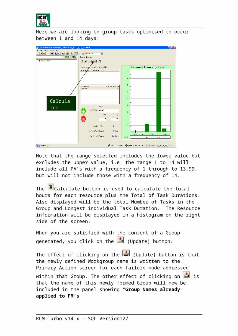
RCM Turbo Failure Mode Library functionThe Library function is used to store and share failure mode and maintenance action details between users.
When a user has completed a complex analysis of a Maintainable Item, its failure mode data may be saved, firstly to a temporary library within the existing RCM Turbo file. It can then be transferred to the Library database using the Library Administration module. Failure modes stored within the temporary library tables can be used over and over within the same RCM Turbo file. When you look at library data, an icon above the equipment type list will tell you whether you are looking at an internal or an external library.
Once data is transferred into any shared Library database, all users who have access to the Library may share it. However, only the Library Administrator may change data within the library. The following describes the procedure to be followed:
Operation of Failure Mode Data Library
RCM Turbo contains a library sub-system to facilitate the sharing of ‘maintainable item’ failure mode data between sites.
The library is designed to store ‘generic’ failure data. The principle is that if a
RCM Turbo v14.x – SQL Version 127
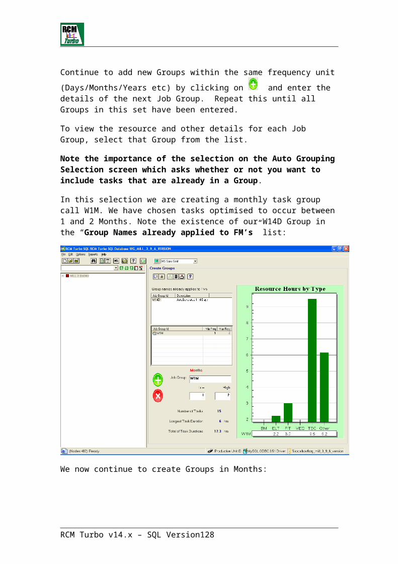
strategy developer at any one site identifies the failure modes of - and develops appropriate maintenance actions for - say, a 75kW electric motor, then that information can be stored in the failure data library. Then any other strategy developer who is also looking at the same type of motor can use that information rather than developing it from scratch.
The failure data library is therefore a ‘productivity tool’ that is designed to assist in the sharing of equipment maintenance information. This has several significant benefits:
· reduction of failure analysis and strategy development time;
· reduction of the need to have specialist technical input on every maintainable item, and;
· provision of a cross-checking process and fertilisation of ideas between sites.
In the strategy development process, plant and equipment information is identified at three levels:
· Productive Unit is used to identify items or ‘blocks’ of equipment that can be analysed at an operational level to establish criticality;
· Maintainable Items are the separately identifiable components which together make up a Productive Unit, and;
· Failure Modes which identify the ways in which each component can fail and which are analysed to establish the appropriate maintenance actions to manage or prevent those failures.
In the strategy development process, the Productive Units and the Maintainable Items are referenced by Plant Index or Equipment Numbers. These are unique to each operating division or site. It is not possible to share maintenance strategy information based on these identifiers unless each site has a detailed knowledge of, and access to every other site’s equipment numbering system or plant index.
The information stored in the Failure Data library must therefore be accessed using a common identifier (or key) which is recognised and understood by each site.
This key is the MACHINE TYPE code that can be assigned to each Maintainable Item record during the strategy development process.
The information stored in the Failure Data Library relates to Machine Type and Failure Mode Analysis data only. The criticality and failure consequence data associated with the operation of the Maintainable Item at each site must be assessed in the context of that site installation and will probably be unique to each installation.
RCM Turbo v14.x – SQL Version 128

Since Machine Type codes will be subject to different levels of interpretation at each site, the Failure Data Library also carries some additional data to assist in selecting and sharing information:
· Each record in the library at Machine Type level will carry a description which can be used to select information when Machine Type codes are not known or are not standardised across divisions, and;
· Each record will carry the name and division of the originator so that verbal contact can be made to discuss the information stored therein.
The general relationship of the data stored in the library and the strategy development system is shown in the diagram below.
The data fields contained in RCM Turbo and library system data records are given in the appendix.
Process for accessing library failure data
Library information can ONLY be accessed from the MAINTAINABLE ITEM data screen in RCM Turbo. The process is as follows:
Create the Maintainable Item record inputting the descriptive data, criticality data and the Machine Type and Modifier codes.
Note 1: the Modifier Code can be used to add an extra level to the Machine Type code to allow for applications of the same Machine Type in different environments which may cause different Failure Modes. It is a mandatory field.
RCM Turbo v14.x – SQL Version 129

Note 2: if a Machine Type code is input, on entry to the Library, RCM Turbo will search the Library to establish whether that code value already exists in the Library and start the display at, or as near as possible to that code.
Select the 'Library' icon to initiate the Library menu. This will give the following options:
Use the first option to access the generic library for review and selection of library data.
To see this function click on ‘List/Get Fail Data from Library’:
RCM Turbo v14.x – SQL Version 130
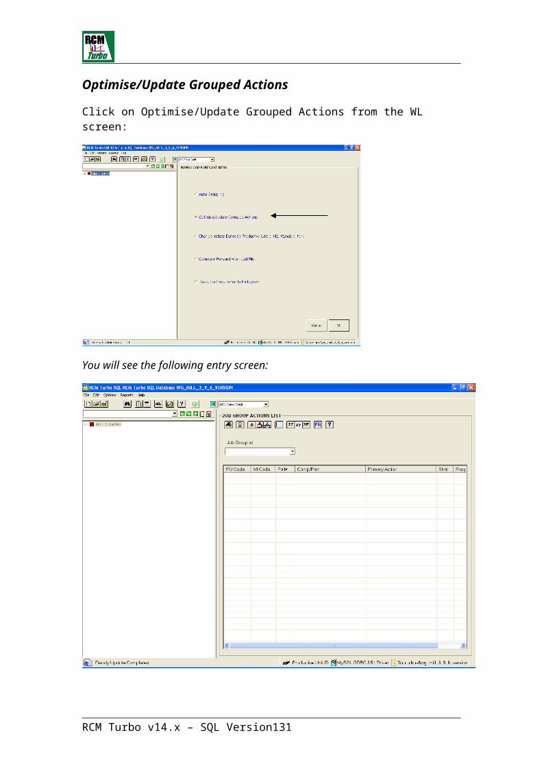
Note: The library contains only the ‘Generic’ data. If this library data has already been used to set up the unique failure and associated strategy data for a similar Maintainable Item at the site/operation being reviewed, then that modified data can be copied from that previous item using the second option.
If a Machine Type / Modifier code has been input on the Maintainable Item screen, then the system will display a list of the Library records starting at that code.
If the code does NOT exist in the library, then the list will start at the code that is nearest in alphabetic-ascending sequence.
If Machine Type / Modifier code has been left blank on the Maintainable Item screen then the system will display a list of the Library records starting at the first record in the Library and the records will be displayed in alphabetic-ascending sequence.
These Library records can be searched to select the required record by entering a Machine Type / Modifier code or by entering a descriptive key word. At each selection, the system will re-start the display list starting at the record that is nearest in alphabetic-ascending sequence. Here is a sample External Library list screen:
In each case, use the cursor to select the required Library record.
Click on this icon to copy the selected Library data and return to the Maintainable Item data input screen.
RCM Turbo v14.x – SQL Version 131

This action will copy all of the failure records associated with the Machine Type/Modifier code in the Library to the Maintainable Item in the Strategy Development System.
Note: If failure data has already been entered into RCM Turbo for the Maintainable Item, the Library data copy will add failure modes to those which already exist.
When you have returned to the Maintainable Item screen, you should then amend the Failure Modes data, consequences, values and associated maintenance actions to suit the specific application of the Maintainable Item / Productive Unit in the plant concerned.
To re-use failure mode information from within your existing RCM Turbo file, click on the third option under the Library menu:
Any equipment types that have been saved in the current file will now be displayed as follows:
RCM Turbo v14.x – SQL Version 132
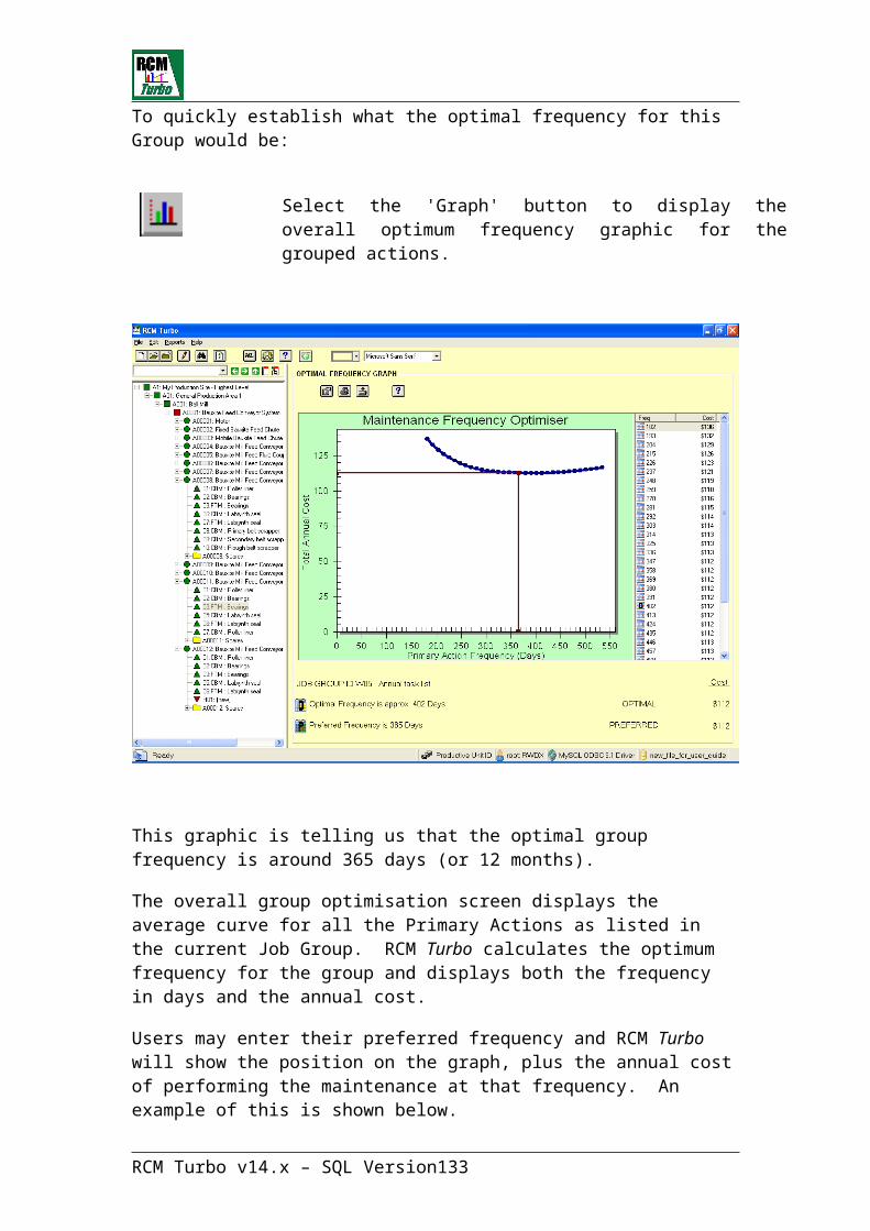
Note that the screen is now showing “Internal” equipment types.
You can re-use failure mode information within the target Maintainable Item
by clicking on the icon in the same way as you would with data from an external library.
Once you have brought any failure mode information in from an external library, the Component Codes and Root Cause Codes will not display until you have run the Verify Component Codes and Verify Root Cause Codes functions. Running these processes ensures that failure mode data to be used in the analysis match the corporation’s defined codes.
It is also possible that an external library will include resource types that do not exist in your current RCM Turbo file. There are two options here.
Firstly, you could revisit each failure mode and apply the correct local resource type to any task information included.
Secondly, you could run the Verify Resource Types function to include Resource Types used in the external library within the RCM Turbo file’s list of resources. This would not be an appropriate step if the resources from the library file are not valid ones in your current environment.
RCM Turbo v14.x – SQL Version 133
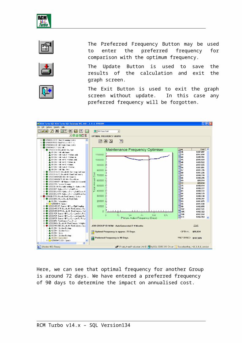
Process for Storing Failure Data in the Library
The process for storing Failure Modes and associated Maintenance action data in the generic Library system is more complex than the information retrieval process due to two simple requirements:
* Data QUALITY CONTROL which requires that there is a level of standardisation in data detail, data coding, data descriptions and identification of data origin, and;
* Library VERSION CONTROL which requires that all sites have access to the latest information containing the latest input and update from all other sites together with their own library updates.
This process therefore requires a level of administration and control as indicated in the diagram below.
This process is described as follows:
Create the Maintainable Item record inputting the descriptive data, criticality data and the Machine Type and Modifier codes using the standard Strategy Development process.
Note 1: the Modifier Code can be used to add an extra level to the Machine Type code to allow for applications of the same Machine Type in different environments which may cause different Failure Modes.
Note 2: if a Machine Type code is input, on entry to the Library, RCM Turbo will search the Library to establish whether that code value already exists in the Library and start the display at, or as near as possible to that code.
You must input the Failure Data before it can be stored in the Generic Library.
When all the required failure data has been entered for the Maintainable Item it should be checked and agreed as representing the appropriate Maintenance Strategy for that item of equipment. Ideally, there should be a sign-off process whereby both maintenance and operations personnel agree that strategy.
RCM Turbo v14.x – SQL Version 134

If the strategy has been agreed and accepted, and you wish to store the failure data in the generic Failure Data Library - return to the Maintainable Item data review screen and
Click on the 'Library' icon to initiate the Library menu. This will give the following options:
Use the second option to save the associated failure and maintenance actions data in temporary library table within your current RCM Turbo file. Failure data cannot be stored directly to the Generic Library file.
Note 1: The process of storing failure data to the temporary library file ADDS data to that file. The temporary library file will therefore grow as more failure data is added and at some time in the process it must be emptied and re-started. Responsibility for this stage of the process rests with the Site Library Administrator.
Note 2: Data stored in this temporary library file can be accessed for update and deletion by using the last option on the library sub-system menu.
Data can be stored into the Temporary Library file by any user of RCM Turbo. If several users run RCM Turbo on separate PC workstations and are NOT sharing their data files, then separate temporary library files will be generated.
RCM Turbo v14.x – SQL Version 135

A Site Library System Administrator should therefore be nominated to oversee the quality control requirements of these data files and to ensure that they are added to the generic library file at appropriate intervals. These functions are performed using the separate program provided, the Library Administration Module.
As appropriate, the Site Library System Administrator will aggregate all users’ temporary library files into a single file for transmission to the Central Library Administrator who in turn will aggregate the files received from all sites into the Generic Library.
The Site Library Administrator should also be responsible for ensuring that when central library updates are performed, each of the local users’ temporary library files are emptied and re-started. The reason for this is to prevent duplicate information being passed into the central Generic Library.
Note: In the absence of any agreement on standardisation of Machine Type / Modifier codes there is no reason why different sites should not have the same code values representing different items of hardware. The Library sub-system will allow duplicate codes, but in the instance of duplicates occurring, the descriptions of Machine Type can be used to differentiate.
A Central Library Administrator should be nominated to receive library updates from all the contributing sites, and to aggregate all those updates into a new version of the Generic Library.
The process of issuing the updated Generic Library and the control of version numbers and dates, etc should also rest with the Central Library Administrator who will pass the updated Generic Library files back to the Site Library Administrators for distribution and update of all users’ PC workstations.
RCM Turbo v14.x – SQL Version 136
Failure Mode Library Administration programThe utility provided for the maintenance of the generic Failure Data Library is the executable program LIBRARY.EXE.
This utility program is for the use of the Library Administrator and provides several important library data management functions:
· It allows the review and update of failure data downloaded from users’ RCM Turbo database for quality and standardised descriptions checking prior to uploading into the generic failure data library;
· It allows the uploading of users’ failure data into the generic library;
· It allows the review and update of failure data already uploaded into the generic library, and;
· It allows merging of multiple generic libraries.
· It allows the Administrator to directly add Machine Types and associated failure mode data to a Library file.
This library data management utility is intended for the use of a designated Library Administrator only, as this person should have ultimate responsibility for the quality of data entered into the generic failure data library.
The procedures and responsibility for library administration described in this documentation are only recommendations - the actual procedures and responsibilities adopted by RCM Turbo users are subject to user requirements and user discretion at each site. Here is the first screen in this module:
RCM Turbo v14.x – SQL Version 137

Step 1 for the Library Administrator will be to create a new Library file for eventual sharing within the site(s):
This will present the following screen:
The next step is to “Merge” into this newly created Library, any valid failure mode data available from RCM Turbo files.
In our RCM Turbo file, we have defined a Machine Type and Modifier for one particular Maintainable Item (the Bauxite Mill Feed Conveyor Gearbox).
To copy these failure modes into the newly created Library, we click on the Merge button:
RCM Turbo v14.x – SQL Version 138

Here, we can select the RCM Turbo data file in question as the FROM selection:
Next we see the TO selection, which should be the current Library file:
A summary screen will then show you what is going to happen:
RCM Turbo v14.x – SQL Version 139
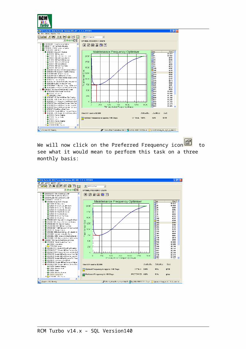
After successful import of the failure mode data from the chosen file, the final option is to ‘clear’ the working failure mode library data from the user’s RCM Turbo file:
Answering ‘No’ here will leave the temporary library within the user’s file. It may be that their file is not yet complete for instance. If the user’s file is complete, then it is safe to clear their temporary files.
Now we are ready to ‘Open’ the newly created library:
We can see that there is only one Machine Type now in the Library.
Clicking on the record will open the Library file at the first failure mode for that Machine Type:
RCM Turbo v14.x – SQL Version 140
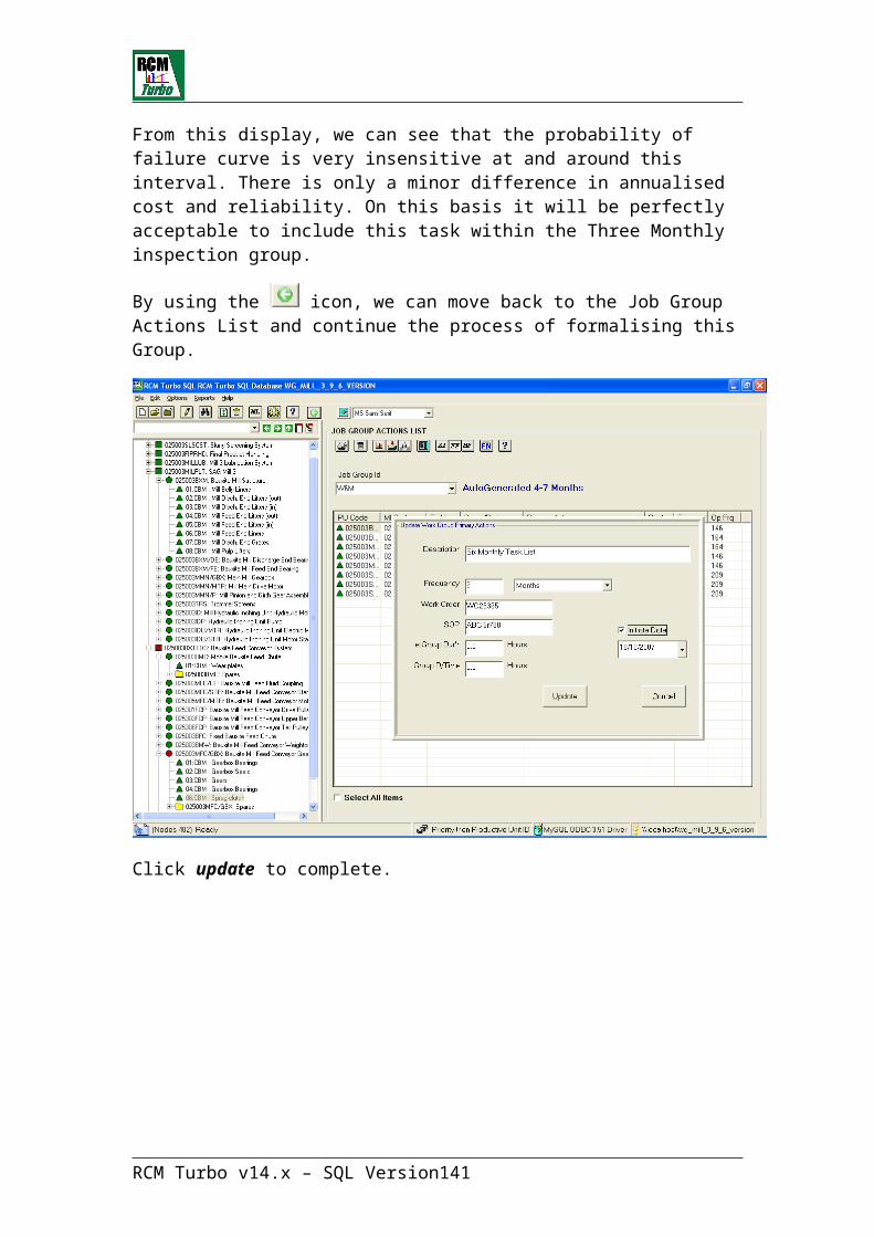
The information available here is identical to that generated within the original RCM Turbo file. Thus, when the corporate library is made available to all other users, failure mode data by Machine Type will because available to them.
Note that the only information included in the Library is failure mode and task data. No optimisation data is retained because that data is reliant upon the operating conditions and parameters of the equipment location in which the failure mode information is going to be used.
Library Administrators are also able to directly enter data to a Library file. To
do this, click on - add new record. This will bring up a screen which is the same as an RCM Turbo user would see when saving failure modes to a temporary library within his own file:
RCM Turbo v14.x – SQL Version 141
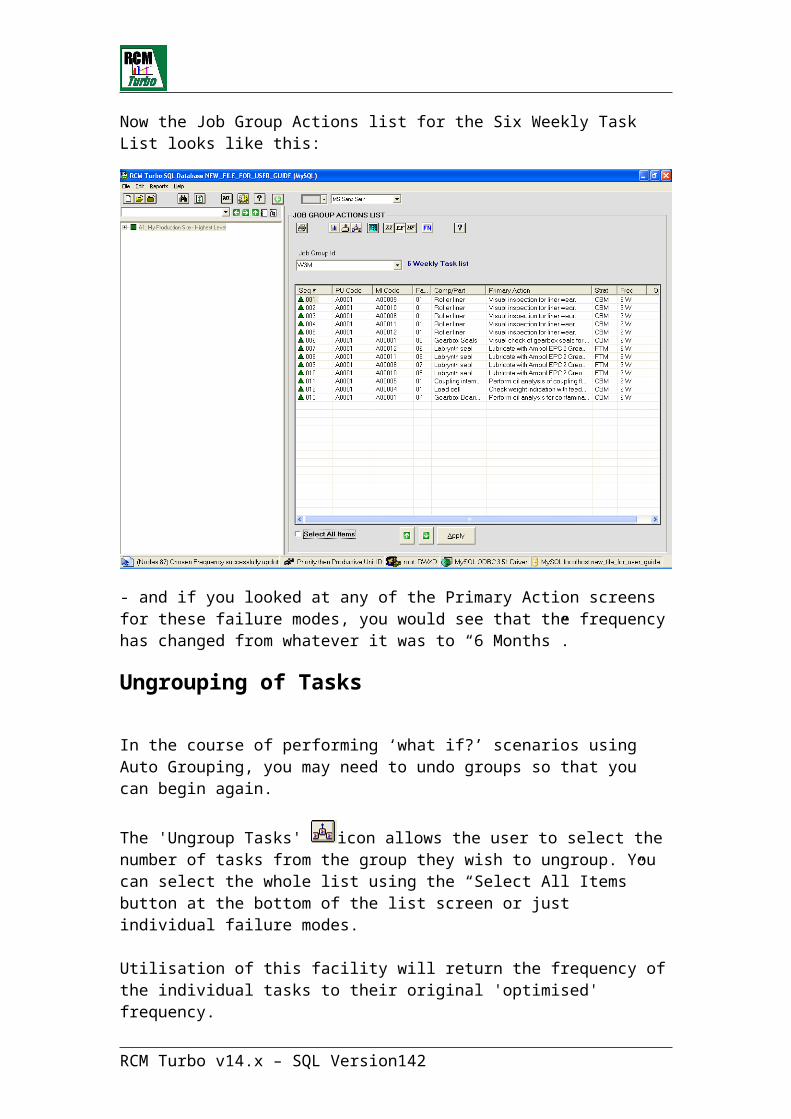
Just as within RCM Turbo, the system needs a Machine Type and Modifier, an Originator, a Division and a general Description of the equipment which is subject to these failure modes.
We now see the extra Machine Type in the list from the Library main screen:
RCM Turbo v14.x – SQL Version 142
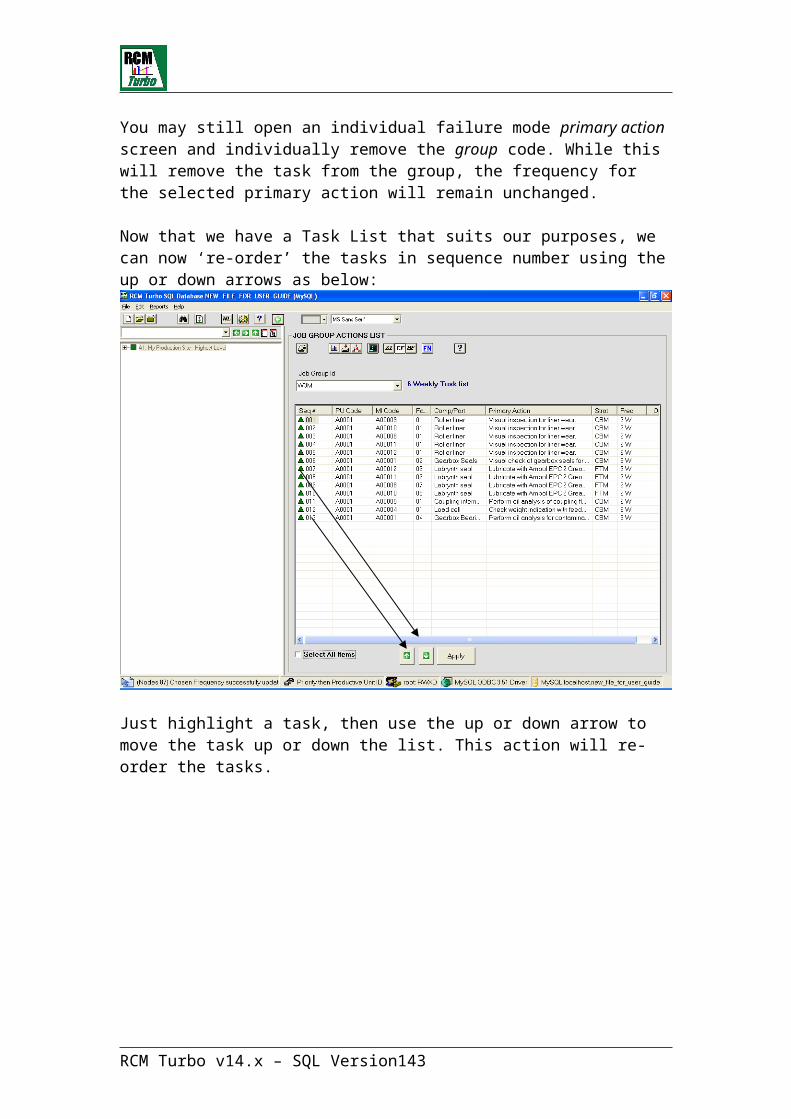
If you double click on the GBOX Machine Type, the Library Administration Module will allow the Administrator to direct add new failure mode information:
When a corporate failure mode library has been fully populated, the Administrator should then ensure that it is made accessible to all users through the SQL database administration functions.
RCM Turbo v14.x – SQL Version 143
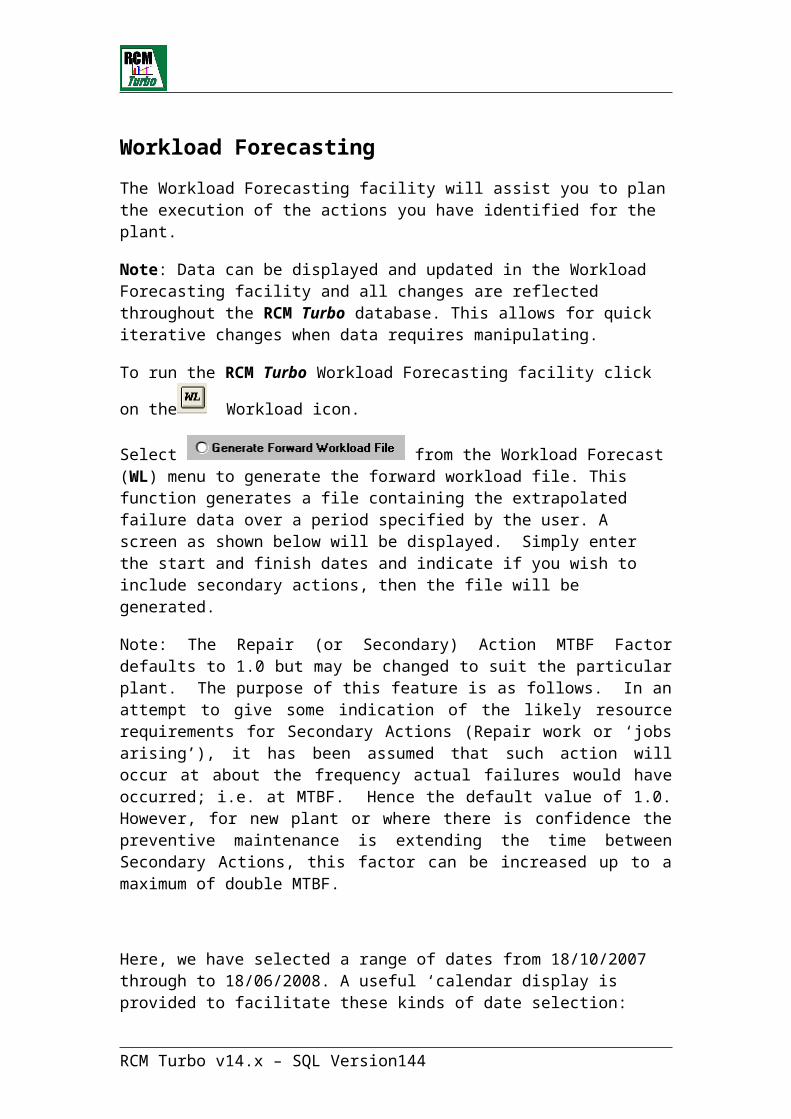
Criticality Assessment Question Set Interpretation
General Guidance: Absolute precision is not required when answering the RCM Turbo screening questions. If you are not sure whether to select between answers 1 or 2 or between answers 2 and 3, go with your gut feeling but with a tendency to choose the more critical answer. The final result of the screening is a relative priority and the impact of a few questions will have only a minor impact on the results. Even then the priority does not have any effect on the maintenance optimization. The intention is to ‘prioritize’ the assets so that at any future time, you can re-display the equipment hierarchy in ‘priority’ order.
The questions are shown in black while the explanations are shown in blue.
Productive Unit Criticality Questions and Responses
1. ASSESS LEGAL LIABILITYIS THE ITEM SUBJECT TO LEGAL REQUIREMENTS?
1. Yes, specific legal maintenance requirements apply. 2. General legal requirements apply to the area but, not to this specific
item. 3. No legal requirements, or not applicable.
This question is to determine whether specific maintenance requirements exist from legal entities such as laws, regulations, operating license, commitments, or codes. The following should be applied when selecting the answer:
1. Is selected when a law, code, or commitment explicitly requires that a specific maintenance activity is to be accomplished and records must be kept.
2. Is selected for Technical Specification surveillance items or other regulatory requirements of a non-specific nature.
3. Is selected when there are no legal maintenance requirements.
2. ASSESS SAFETY LIABILITYDOES FAILURE CONSTITUTE A SAFETY HAZARD?
1. Failure consequence normally creates a serious hazard. 2. Uncontrolled failure normally leads to equipment or environmental
damage. 3. Failure consequence causes no hazard.
This question is to ascertain if a failure would result in an industrial, environmental or personnel safety hazard. The following should be applied when selecting the answer:
RCM Turbo v14.x – SQL Version 144
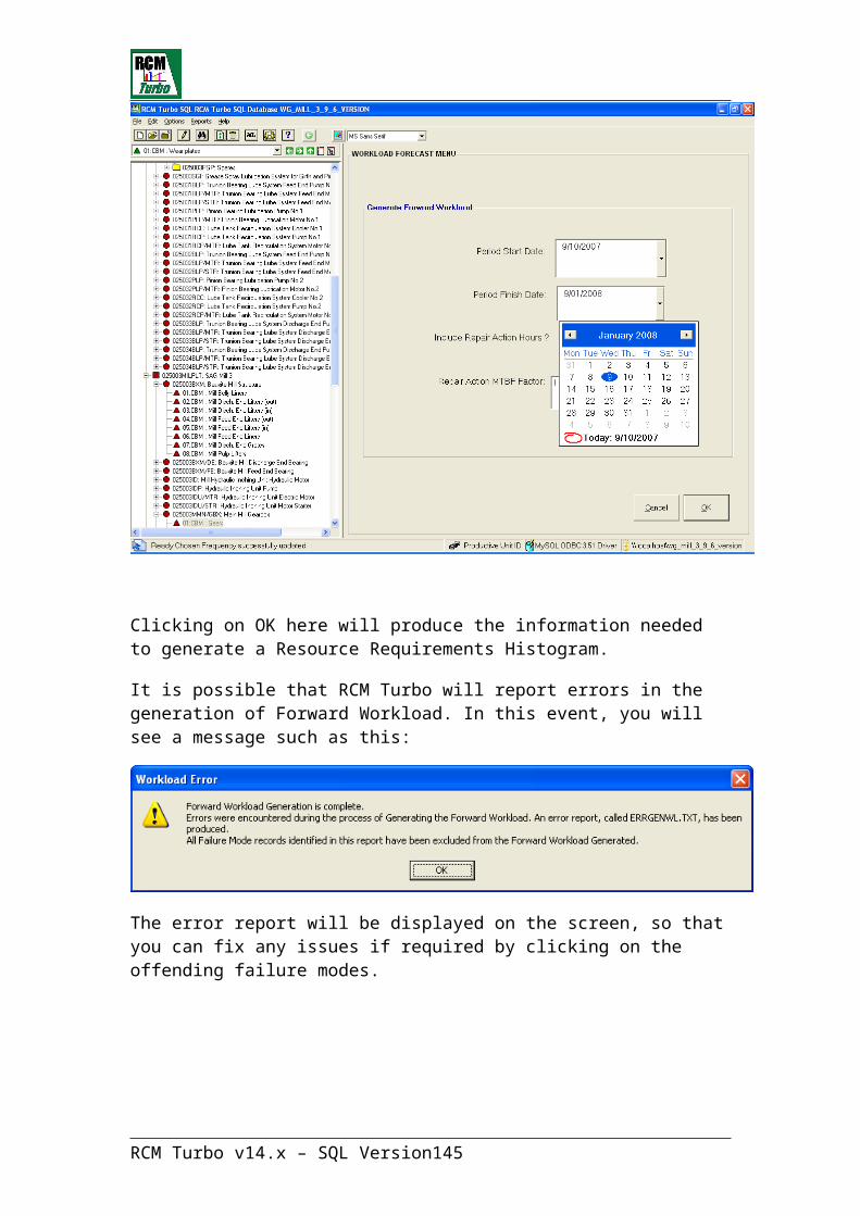
1. Is selected when the expected failure mode(s) would create a life threatening condition.
2. Is selected when the expected failure mode(s) could lead to additional equipment damage beyond the original failure OR results in environmental contamination.
3. ASSESS LOSS CONSEQUENCEWHAT IS THE EXPECTED LOSS DUE TO ITEM FAILURE?
1. Definite loss of production or critical support system. 2. Possible loss of production or critical support system capability. 3. No expected loss of production within typical repair time.
This question is to determine the consequences of a component or equipment failure to the business. The key areas of consideration are the impact to production and support systems critical to maintaining production or safety. The following should be applied when selecting the answer:
1. Is selected when loss of the item definitely causes a loss of production. 2. Is selected when loss of the item might result in a loss of production or
the loss of redundancy. 3. Is selected when there is no expected loss of production due to the
failure.
4. ASSESS DAMAGE CONSEQUENCEWHAT IS THE AVERAGE REPAIR COST FOR ITEM FAILURE?
1. Major repairs, refurbishment, or environmental clean-up required 2. Minor repairs or clean-up (minimal environmental impact) 3. None, or not applicable.
This question determines the cost impact if the equipment were to fail. This cost does not include lost production. This cost does include the actual repair and cleanup activity. The following should be applied when selecting the answer:
1. Is selected when repair costs are expected to be considered high in your organization.
2. Is selected when repair costs are expected to be considered minor. 3. Is selected when repair costs are expected to be very low.
5. ASSESS RISK BASED ON FAILURE PROBABILITIESIS THE ITEM LIKELY TO FAIL IN SERVICE?
1. Failures are common (e.g. >5 times per year) 2. Failures are infrequent (e.g. 2 to 5 times per year) 3. Item is rugged, in reasonable condition, and is unlikely to fail (e.g. < 2
per year)
This question ranks how likely the item is to fail in service. A failure is considered to be a condition that results in a loss of function of the system or component being evaluated. On-site and industry operating experience should be considered in answering this. The question should be answered
RCM Turbo v14.x – SQL Version 145
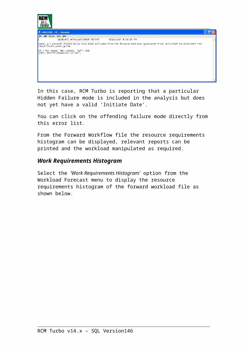
with respect to the items current condition.
6. ASSESS RISK BASED ON FAILURE PREDICTABILITYCAN FAILURE BE PREDICTED?
1. Very difficult or impossible (no access/no detectable symptoms). 2. Moderately difficult, but possible to prevent failures (CBM?). 3. Relatively easy to predict and repair before failure.
This question addresses if a failure can be predicted BEFORE the failure actually occurs. The following should be applied when selecting the answer:
1. Is selected when the item cannot be monitored to predict failure. It may be due to inaccessibility, lack of instrumentation, or there is no technology that can predict failure.
2. Is selected when some form of technology can predict failure in advance. This may be by condition monitoring, trending, vibration, themography, etc.
3. Is selected when failure can be predicted by simple (non-technology) monitoring methods such as sight, hearing, smell, or touch.
7. ASSESS IMPACT TO PRODUCTION WHAT IS THE PRODUCT LOST DURING REPAIR DOWNTIME?
1. High-value primary products or key process/safety utilities 2. Low-value processes, general utilities, or inter-plant work in progress. 3. General services, no product loss, or not applicable.
This question directly addresses a more precise impact to unit production particularly where there are multiple products being manufactured of differing profitability. If the system or component were to fail, is a high or low profit item that is lost? This question should be answered considering system and component redundancy. The following should be applied when selecting the answer:
1. Is selected when the item failure would directly result in a production loss of a high profit product.
2. Is selected when the item failure would result in a loss of secondary products or if there is storage in the process after this point.
3. Is selected when there is no production loss from item failure.
8. ASSESS IMPACT TO SALESWHAT POTENTIAL SALES OR MARKET LOSSES MIGHT BE SUFFERED?
1. Direct loss of sales, or breaks customer supply contract requirements. 2. Possible loss of sales or customer service (situation recoverable). 3. None, or not applicable.
This question addresses the situation where there is no storage before delivery to the customer and there exists direct competitors in the
RCM Turbo v14.x – SQL Version 146

marketplace.
9. ASSESS SUBSTITUTION POSSIBILITIESCAN A SUBSTITUTE ITEM OR SYSTEM BE USED AS A TEMPORARY MEASURE?
1. No, item must be repaired to resume full production. 2. Substitution/bypass is possible but difficult or inefficient. 3. Not necessary, or substitution is easy and readily available.
This question is to assess the possibility of providing a temporary substitute to restore production should the equipment fail. Be sure to consider ALL alternative possibilities beyond just repairing the equipment. The following should be applied when selecting the answer:
1. Is selected when there are no practical substitution possibilities and the item is required for full production.
2. Is selected when substitution is possible but difficult. 3. Is selected when substitution is not necessary or not complex. Not
complex means:
· Manual operator action can restore function and, · Easily identifiable by operator and· Expected to be recovered in a timely manner
.
10. ASSESS SUBSTITUTION COSTSWHAT IS THE COST OF SUBSTITUTION/BYPASS?
1. Major cost of equipment rental and/or plant modification. 2. Relocation and hook-up of standby equipment. 3. No action required, or simple use of other equipment.
This question is a follow-up to question 9. How cost effective is it to provide a temporary substitution?
11. ASSESS RE-START REQUIREMENTSWHAT ARE THE RE-START PROCEDURE REQUIREMENTS AFTER FAILURE?
1. Major re-start/re-heat/synchronization of process or support equipment. 2. Re-start of associated equipment within normal operating procedures. 3. Negligible, or not relevant (simple on/off switch).
This question is to determine the difficulty of recovering from a failure. This question is not directed at the repair activity itself, but in restoring the equipment to service.
12. ASSESS INDIRECT COSTS
RCM Turbo v14.x – SQL Version 147
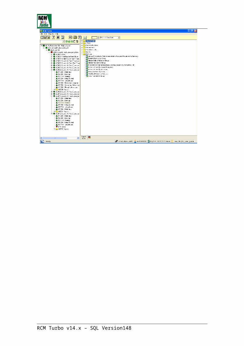
WHAT IS THE INDIRECT COST IMPACT OF UNPLANNED FAILURE?1. Major operational costs incurred. 2. Manageable costs, or opportunity maint. can be done. 3. Negligible, or not relevant.
Indirect costs are those additional costs due to the failure which would not have been expended had the repair been planned. These costs include resources to troubleshoot and identify root cause, additional vendor and contract support. The following should be applied when selecting the answer:
1. Select if expected failure mode(s) are expected to be a significant site resource intensive flail.
2. Select if some indirect costs are involved but not expected to achieve flail status.
3. Select if negligible.
Maintainable Item Criticality Questions and Responses
13. ASSESS FAILURE CAUSEWHAT IS THE CAUSE OF NORMAL FAILURE ON THE ITEM?
1. Abnormal loading, accident, or consequence of other failure. 2. Internal normal wear and tear, corrosion, or drift from setting. 3. External effects, such as water/dirt ingress, corrosion, leakage, etc.
Self-explanatory.
14. ASSESS FAILURE CHARACTERISTICWHAT IS THE EXPECTED CHARACTERISTIC OF NORMAL ITEM FAILURE?
1. Sudden and unpredictable (no detectable early warning). 2. Relatively slow but noticeable (repairs can be planned). 3. Measurable, gradual, and/or controllable (repairs can be planned).
Self-explanatory.
15. ASSESS GENERAL RELIABILITY TRAITSDOES THE ITEM HAVE AN IN-SERVICE DESIGN LIFE?
1. Life is not known and failure is likely at any time. 2. Failure is likely after an average or known design life. 3. Item has an indefinite life and is unlikely to fail.
Self-explanatory.
16. ASSESS MONITORING CAPABILITIESCAN THE ITEM BE MONITORED TO PREDICT FAILURE?
1. No, regular inspection or monitoring provides no benefit. 2. Yes, but requires technical monitoring methods. 3. Yes, by simple manual/visual inspection and testing.
RCM Turbo v14.x – SQL Version 148
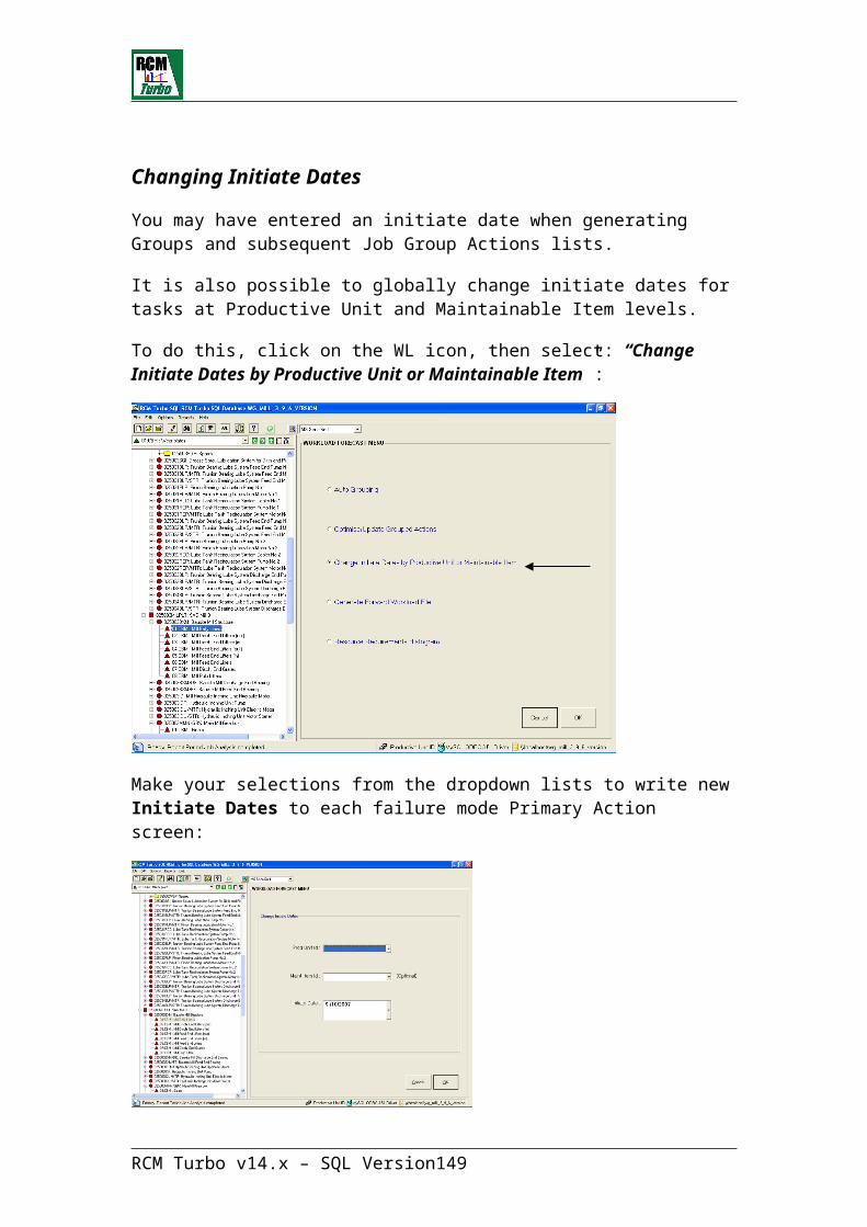
This question addresses the technical possibility of predicting failure. It does not ask if this is currently being carried out. If test or monitoring equipment or special training is required, number 2 should be selected. This includes thermography, vibration analysis, and other predictive technologies. This question should be answered based on the technology available in the industry regardless of whether it is available on site or not.
17. ASSESS MAINTAINABILITYWHAT IS THE GENERAL CONDITION OF THE ITEM?
1. Poor (unreliable, worn, and documentation is out of date). 2. Medium (some difficulty in obtaining information/spares, etc.). 3. Not relevant, or excellent and well documented/highly reliable.
Self-explanatory.
18. ASSESS REPAIR SKILL REQUIREMENTSWHAT ARE THE SKILL REQUIREMENTS FOR SERVICE AND REPAIR?
1. High level skills in short supply (such as technology/diagnostics). 2. Normal trades skills (no specialist knowledge required). 3. Minimal skills (such as cleaning, lubrication, adjustments, etc.).
Self-explanatory.
19. ASSESS SPARE CAPACITY COSTSWHAT IS THE COST FOR PROVIDING SPARE CAPACITY?
1. In-line redundancy/spare unit not practical/cost justifiable. 2. In-line redundancy/spare unit difficult and expensive. 3. Not necessary, or cheap and easy to duplicate/replace item.
If a component has an installed redundant component that can maintain full production capability, answer 3 should be selected i.e. spare capacity already exists.
20. ASSESS MAGNITUDE OF REPAIRWHAT IS THE EXTENT OF PROBABLE REPAIR ON THIS ITEM?
1. Major overhaul, or major dismantling and in-place rebuild. 2. Dismantling, internal inspection/cleaning, and parts replacement. 3. Simple re-setting, simple parts replacement, or simple change-out.
This should be answered with respect to the most probable extent of repair. To determine this, it is more important to determine the most likely failure modes and not the worst case.
RCM Turbo v14.x – SQL Version 149

RCM Turbo Assessment Templates
On the installation CD-ROM you will find a directory called ‘Assessment Templates’. These are generic RCM Turbo assessment files for equipment as indicated by each file name.
In the MySQL environment, all that is needed to utilize any of these files is to ‘restore’ them in the MySQL Server by using the restore function within the MySQL Administrator software.
RCM Turbo v14.x – SQL Version 150
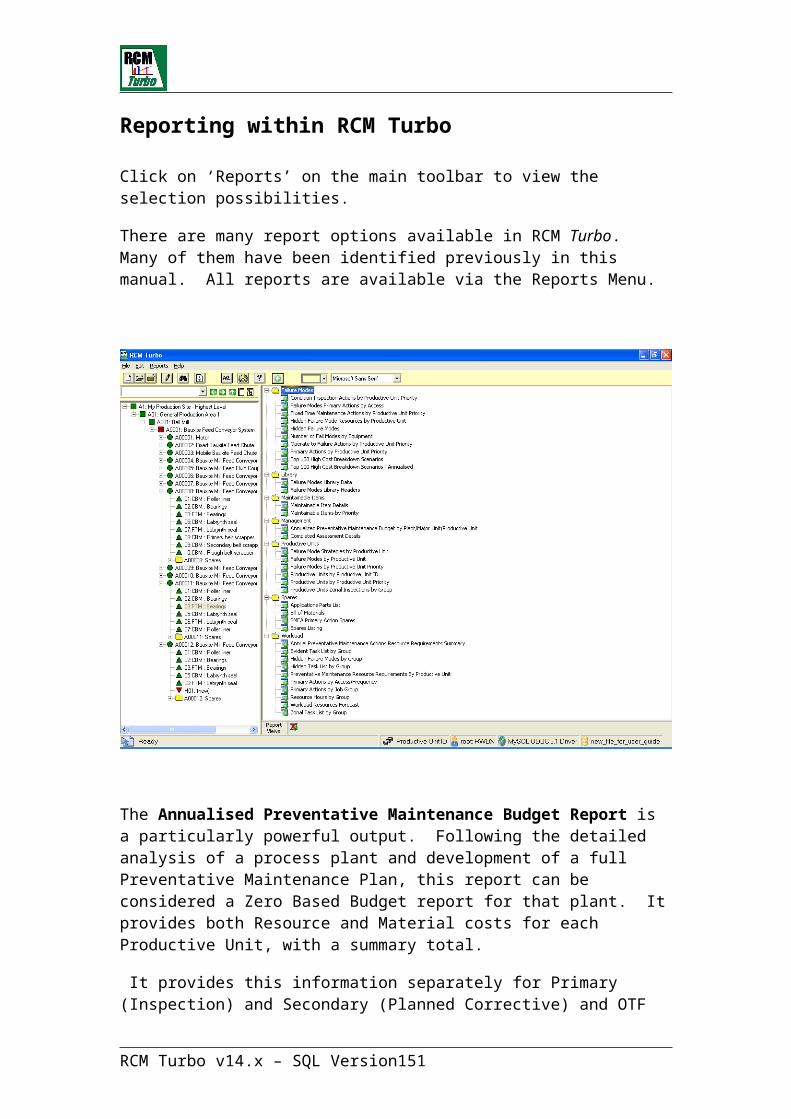
Running RCM Turbo in Special Modes
The RCM Turbo executable can be run using ‘switches’ to turn on certain functions.
The first of these is the <-captions> option. In this mode, RCM Turbo will display a log of all activity in the current user session.
This mode should be used if there is a need to report any problem(s) to Strategic.
Captions mode can be selected from the START/ PROGRAMS /RCM TURBO SQL V14/ SUPPORT group.
Alternatively a shortcut to RCM Turbo can be created that would look like the following command line (using your own path description to the RCM Turbo executable):
"C:\Program Files\RCMT SQL version\RcmtSQL.exe" –captions
There is also a ‘log’ mode. This too can be selected from the START/ PROGRAMS/ RCM TURBO SQL v14/ SUPPORT group. Using this mode, any problems found in the running of RCM Turbo can be logged in a file that can be forwarded to Strategic.
RCM Turbo v14.x – SQL Version 151

User Definition and SecurityRCM Turbo uses the MySQL database for storage of data and for security and definition of Users. Using the MySQL Administrator software, Users can be defined as can their access rights.
MySQL Administrator
Click on the MySQL Administrator icon to run the program. You will be asked to login as follows:
RCM Turbo will be supplied with a default highest level authority login and password of:
Login <root>Password <strategic>
This combination of UID and password may be changed by a system administrator at a subsequent time.
It is expected that additional users will be allocated by the system administrator after initial installation. Normal users will login using their (later) assigned logins and passwords.
The opening screen in MySQL Administrator looks like this:
RCM Turbo v14.x – SQL Version 152
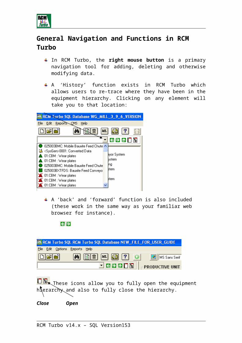
RCM Turbo v14.x – SQL Version 153

User AdministrationOne of the first functions the system administrator should perform is to allocate new User ID’s (UID’s) and passwords to potential RCM Turbo users.
Click on User Administration, then Add New User to begin this process:
RCM Turbo v14.x – SQL Version 154

Here we have added a new user a password and his other details. As with RCM Turbo, we now need to ‘Apply’ these additions. The next step is to assign access and privileges to this user. Click on ‘Global Privileges’.
Using the Left and Right Arrow icons, you can add and remove access rights and the ability to update, delete, execute, etc against any files in the MySQL database for this user.
RCM Turbo v14.x – SQL Version 155
If this new user is to have the highest level access and permission to carry out any functions within RCM Turbo, then use the ‘double arrows’ to move all the options to the left pane and then click on ‘Apply’:
Using this function, you can limit a user to ‘read-only’ access for instance.
Using the MySQL Administrator, it is also possible to secure individual databases used by RCM Turbo in different ways for each user.
It may be that there is a site ‘masterfile’ in place, which may have been used to transfer final optimised maintenance plans to the CMMS. Such a file should be protected against unauthorised use. This is achieved by specifically selecting the target file from a list of existing RCM Turbo files as per the following screen.
RCM Turbo v14.x – SQL Version 156
Here we have chosen the file ‘wg_mill_9.6’. For the newly created user <Frank>, we can now assign rights and privileges from the right hand pane as we did above for general access.
Assigning the ‘Select’ function only for instance would provide read-only access to user Frank.
RCM Turbo v14.x – SQL Version 157
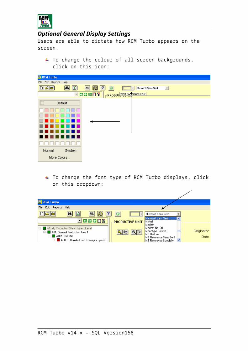
Backup RCM Turbo files
The backup and restore procedures for RCM Turbo using MySQL Administrator are both powerful and simple.
To perform a backup of an RCM Turbo file or files, click on Backup from the MySQL Administrator menu as follows:
All the RCM Turbo files that exist on the server are visible though greyed out in this initial view. To backup one of the files (say the first on the list above which is <acid_plant-master>), click on ‘New Project’ to illuminate the list. Now click on the required file. You can now give this backup ‘project’ a name:
Next, we click on the right facing arrow to include the required file in the backup project. This will display the file and its contents as follows:
RCM Turbo v14.x – SQL Version 158
The next step is to ‘Execute’ the backup. MySQL Administrator will now ask you to nominate the location for the new backup file:
Put the backup file into a secure location of your choice. On doing this, you will see the progress of the backup displayed:
RCM Turbo v14.x – SQL Version 159

On completion, a screen like this will appear:
This backup file is now ready for future ‘restore’ if required.
RCM Turbo v14.x – SQL Version 160

Restore RCM Turbo files
The reverse of the Backup process is restoring a file. Click on Restore to begin.
If we wish to ‘restore’ the acid_plant_master file, we would click on ‘Open Backup File’ to select the file to be restored:
Now click on ‘Open’ to bring the backup file in:
RCM Turbo v14.x – SQL Version 161

Finally, click on ‘Start Restore’ to complete the restoration of the file.
A progress bar will appear:
Using this facility, even very large files can be backed up and restored very quickly.
RCM Turbo v14.x – SQL Version 162
Support from Strategic
Should a problem ever arise with an RCM Turbo file, you can provide Strategic with a copy of the file using the backup function. Simply email your Strategic representative a copy of the backup ‘.sql’ file.
Support services are provided under the terms of an annual Software Support and Update agreement which your organization will complete with Strategic.
RCM Turbo v14.x – SQL Version 163

Troubleshooting
The successful installation of MySQL Server and the RCM Turbo application is dependent upon a number of local IT conditions.
These include:
The latest Microsoft MDAC software add-on’sThe latest Microsoft ‘Installer’ softwareThe access rights available to the individual performing the installations
Other issues:
Should it become necessary to re-install MySQL Server, then the previous installation must be ‘un-installed’. After this un-install, you must also manually remove the MySQL installed directory to ensure that all remnants of the original installation are removed.
If a re-installation of MySQL Server becomes necessary and you have been successfully using RCM Turbo prior to this need, ensure that you use the MySQL Administration program to ‘backup’ any existing RCM Turbo data files that may have been created. You should also backup the RCM Turbo system files <rcmtsos96r.mda> and <rcmtsos96s.mda>. All these will be needed when you have successfully re-installed My SQL Server.
RCM Turbo v14.x – SQL Version 164