rc3000 rev.b pcm multi-service multiplexer user manual...
TRANSCRIPT

www.raisecom.com
RC3000 (REV.B) PCM Multi-service Multiplexer User Manual

Legal Notices
Raisecom Technology Co., Ltd makes no warranty of any kind with regard to this manual, including, but not limited to, the implied warranties of merchantability and fitness for a particular purpose. Raisecom Technology Co., Ltd shall not be held liable for errors contained herein or direct, indirect, special, incidental or consequential damages in connection with the furnishing, performance, or use of this material.
Warranty.
A copy of the specific warranty terms applicable to your Raisecom product and replacement parts can be obtained from Service Office.
Restricted Rights Legend.
All rights are reserved. No part of this document may be photocopied, reproduced, or translated to another language without the prior written consent of Raisecom Technology Co., Ltd. The information contained in this document is subject to change without notice.
Copyright Notices.
Copyright ©2009 Raisecom. All rights reserved. No part of this publication may be excerpted, reproduced, translated or utilized in any form or by any means, electronic or mechanical, including photocopying and microfilm, without permission in Writing from Raisecom Technology Co., Ltd.
Trademark Notices
is the trademark of Raisecom Technology Co., Ltd.
Java™ is a U.S. trademark of Sun Microsystems, Inc.
Microsoft® is a U.S. registered trademark of Microsoft Corporation.
Windows NT® is a U.S. registered trademark of Microsoft Corporation.
Windows® 2000 is a U.S. registered trademark of Microsoft Corporation.
Windows® XP is a U.S. registered trademark of Microsoft Corporation.
Windows® and MS Windows® are U.S. registered trademarks of
Microsoft Corporation.
Contact Information
Technical Assistance Center
The Raisecom TAC is available to all customers who need technical assistance with a Raisecom product, technology, or, solution. You can communicate with us through the following methods:
Address: 2nd Floor, South Building of Rainbow Plaza, No.11 Shangdi Information Road,
Haidian District, Beijing 100085
Tel: +86-10-82883305
Fax: +86-10-82883056
World Wide Web
You can access the most current Raisecom product information on the World Wide Web at the following URL:
http://www.raisecom.com
Feedback
Comments and questions about how the RC3000 device works are welcomed. Please review the FAQ in the related manual, and if your question is not covered, send email by using the following web page:
http://www.raisecom.com/en/xcontactus/contactus.htm.
If you have comments on the RC3000 specification, instead of the web page above, please send comments to:
We hope to hear from you!

CONTENTS Chapter 1 Product Overview ------------------------------------------------------------------------- 1
1.1 Point to Point application mode--------------------------------------------------------------------------------------------1 1.2 ADM function -------------------------------------------------------------------------------------------------------------------2 1.3 Daisy-chain application ------------------------------------------------------------------------------------------------------2 1.4 Point to Multi-Point application (Star mode) ----------------------------------------------------------------------------3 1.5 Hybrid access of star topology and daisy-chain topology-----------------------------------------------------------3
Chapter 2 Type of Device and Sub-card ---------------------------------------------------------- 5 2.1 Device type ---------------------------------------------------------------------------------------------------------------------5 2.2 Type of sub-card---------------------------------------------------------------------------------------------------------------5
Chapter 3 Technical Specification------------------------------------------------------------------ 7 3.1 Up-link sub-card ---------------------------------------------------------------------------------------------------------------7
3.1.1 E1 interface specification ---------------------------------------------------------------------------------------------------------------- 7 3.1.2 Optical interface specification----------------------------------------------------------------------------------------------------------- 7 3.1.3 Ethernet interface specification--------------------------------------------------------------------------------------------------------- 7
3.2 Down-link sub-card -----------------------------------------------------------------------------------------------------------8 3.2.1 Sub-card of FXS audio user interface (RC3000-SUB-DS) ---------------------------------------------------------------------- 8 3.2.2 Sub-card of FXO audio relay interface (RC3000-SUB-DO) --------------------------------------------------------------------- 8 3.2.3 Sub-card of E&M 2-wire audio relay interface (RC3000-SUB-DM2)---------------------------------------------------------- 8 3.2.4 Sub-card of E&M 4-wire audio relay interface (RC3000-SUB-DM4)---------------------------------------------------------- 9 3.2.5 Sub-card of V35 interface (RC3000-SUB-DV35) ---------------------------------------------------------------------------------- 9 3.2.6 Sub-card of V24 interface (RC3000-SUB-DV24) ---------------------------------------------------------------------------------- 9 3.2.7 Sub-card of Ethernet interface (RC3000-SUB-DETH)---------------------------------------------------------------------------- 9 3.2.8 Sub-card of RS232 interface (RC3000-SUB-D232)------------------------------------------------------------------------------- 9 3.2.9 Sub-card of RS422 interface (RC3000-SUB-D422)------------------------------------------------------------------------------- 9 3.2.10 Sub-card of MT interface (RC3000-SUB-DMT)--------------------------------------------------------------------------------- 10 3.2.11 Sub-card of FXS polarity reversible user interface (RC3000-SUB-DSR)------------------------------------------------- 10 3.2.12 Sub-card of RS485 interface (RC3000-SUB-D485) --------------------------------------------------------------------------- 10 3.2.13 Sub-card of Ethernet interface (RC3000-SUB-DETHB) ---------------------------------------------------------------------- 10 3.2.14 Sub-card of 64K of co-direction data interface (RC3000-SUB-D485)------------------------------------------------------11
3.3 Power supply ----------------------------------------------------------------------------------------------------------------- 11 3.4 Ambiance ---------------------------------------------------------------------------------------------------------------------- 11 3.5 Dimension of chassis------------------------------------------------------------------------------------------------------- 11
Chapter 4 Structure and Indicator-----------------------------------------------------------------12 4.1 Structure of chassis ---------------------------------------------------------------------------------------------------------12 4.2 Front panel --------------------------------------------------------------------------------------------------------------------12
4.2.1 System indicator-------------------------------------------------------------------------------------------------------------------------- 13 4.2.2 Up-link sub-card indicators ------------------------------------------------------------------------------------------------------------ 13 4.2.3 Optical interface indicator -------------------------------------------------------------------------------------------------------------- 13 4.2.4 E1 line indicator -------------------------------------------------------------------------------------------------------------------------- 14 4.2.5 Definition of mute, DIP switch and interfaces ------------------------------------------------------------------------------------- 14
4.3 Rear panel---------------------------------------------------------------------------------------------------------------------15 4.3.1 Slot of user interface sub-card-------------------------------------------------------------------------------------------------------- 15 4.3.2 Up-link interface -------------------------------------------------------------------------------------------------------------------------- 16 4.3.3 Power supply interface ----------------------------------------------------------------------------------------------------------------- 17
Chapter 5 Function and Application --------------------------------------------------------------18 5.1 Function and application of RC3000 host-------------------------------------------------------------------------18
5.1.1 Default setting----------------------------------------------------------------------------------------------------------------------------- 18 5.1.2 Self-check and startup ------------------------------------------------------------------------------------------------------------------ 18 5.1.3 Explanation of system automatic configuration in factory default status --------------------------------------------------- 18 5.1.4 Clock switch explanation --------------------------------------------------------------------------------------------------------------- 19 5.1.5 Automatic crossover setting ----------------------------------------------------------------------------------------------------------- 19 5.1.6 System and crossover setting -------------------------------------------------------------------------------------------------------- 20 5.1.7 Device alarms----------------------------------------------------------------------------------------------------------------------------- 20 5.1.8 Network management channel ------------------------------------------------------------------------------------------------------- 21 5.1.9 Port definition ----------------------------------------------------------------------------------------------------------------------------- 22
5.2 Function of RC3000-SUB-DS ----------------------------------------------------------------------------------------23 5.3 Function of RC3000-SUB-DO----------------------------------------------------------------------------------------24 5.4 Function of RC3000-SUB-DSO--------------------------------------------------------------------------------------25 5.5 Function of RC3000-SUB-DM2--------------------------------------------------------------------------------------26
5.6 Function of RC3000-SUB-DM4--------------------------------------------------------------------------------------27 5.7 Function of RC3000-SUB-DV35-------------------------------------------------------------------------------------28
5.7.1 Rules for channel allocation ----------------------------------------------------------------------------------------------------------- 28 5.7.2 Definition of V35 interface ------------------------------------------------------------------------------------------------------------- 29 5.7.3 Setting of V35 sub-card ---------------------------------------------------------------------------------------------------------------- 30
5.8 Function of RC3000-SUB-DETH ------------------------------------------------------------------------------------30 5.8.1 Rules for channel allocation ----------------------------------------------------------------------------------------------------------- 30 5.8.2 Definition of Ethernet interface ------------------------------------------------------------------------------------------------------- 30 5.8.3 Setting of Ethernet sub-card ---------------------------------------------------------------------------------------------------------- 30
5.9 Function of RC3000-SUB-D232 -------------------------------------------------------------------------------------31 5.9.1 Interface reference of RS232 --------------------------------------------------------------------------------------------------------- 31
5.10 Function of RC3000-SUB-D422 -------------------------------------------------------------------------------------32 5.11 Function of RC3000-SUB-DMT--------------------------------------------------------------------------------------32 5.12 Function of RC3000-SUB-DSR--------------------------------------------------------------------------------------33 5.13 Function of RC3000-SUB-D485 -------------------------------------------------------------------------------------34 5.14 Function of RC3000-SUB-DSR(-48V) -----------------------------------------------------------------------------35 5.15 Function of RC3000-SUB-DETHB ----------------------------------------------------------------------------------35
5.15.1 Rules for channel allocation --------------------------------------------------------------------------------------------------------- 35 5.15.2 Definition of Ethernet interface------------------------------------------------------------------------------------------------------ 35 5.15.3 Setting of Ethernet sub-card--------------------------------------------------------------------------------------------------------- 35
5.16 Function of RC3000-SUB-DETHx2---------------------------------------------------------------------------------36 5.16.1 Rules for channel allocation --------------------------------------------------------------------------------------------------------- 36 5.16.2 Definition of dual-Ethernet interface ----------------------------------------------------------------------------------------------- 36 5.16.3 Setting of Ethernet sub-card--------------------------------------------------------------------------------------------------------- 36
5.17 Function of RC3000-SUB-DV24-------------------------------------------------------------------------------------36 5.17.1 Timeslot setting rules ------------------------------------------------------------------------------------------------------------------ 38
5.18 Function of RC3000-SUB-DC64K ----------------------------------------------------------------------------------38 5.18.1 Panel diagram ---------------------------------------------------------------------------------------------------------------------- 38 5.18.2 Indicator description -------------------------------------------------------------------------------------------------------------- 38 5.18.3 Interface diagram ------------------------------------------------------------------------------------------------------------------ 38 5.18.4 Definition of interface ------------------------------------------------------------------------------------------------------------- 39
5.19 Function of RC3000-SUB-10FXS card ----------------------------------------------------------------------------39 5.20 Function of RC3000-SUB-10FXO card ----------------------------------------------------------------------------40 5.21 Function of RC3000-SUB-OPT-FE ---------------------------------------------------------------------------------41 5.22 Function of RC3000-SUB-OPT-2E1--------------------------------------------------------------------------------42
Chapter 6 Installation and Testing-----------------------------------------------------------------44 6.1 Unpacking check-up --------------------------------------------------------------------------------------------------------44 6.2 Preparation before installation -------------------------------------------------------------------------------------------44 6.3 Installing process ------------------------------------------------------------------------------------------------------------44
6.3.1 Fix the device -------------------------------------------------------------------------------------------------------------------------- 44 6.3.2 Connecting cables -------------------------------------------------------------------------------------------------------------------- 44 6.3.3 Power on and setting the device -------------------------------------------------------------------------------------------------- 45
Chapter 7 FAQ--------------------------------------------------------------------------------------------46 7.1 SYS is ON-----------------------------------------------------------------------------------------------------------------46 7.2 Alarms of E1 interface--------------------------------------------------------------------------------------------------46 7.3 Cross connection cannot communicate normally ---------------------------------------------------------------46 7.4 There is no alarm but voice channel is discontinuous or communication is abnormal ----------------46 7.5 There is LOF or RAL alarms sometimes of E1 interface------------------------------------------------------47 7.6 Not all devices in a network can be network managed--------------------------------------------------------47 7.7 Device cannot be configured through CONSOLE --------------------------------------------------------------47 7.8 Memory information loss ----------------------------------------------------------------------------------------------47 7.9 Display of device is abnormal ----------------------------------------------------------------------------------------48 7.10 Forget the password----------------------------------------------------------------------------------------------------48 7.11 User port alarm indication of self-loop DC64K sub-card is inconsistent for different uplink cards -48
Appendix A How to use Hyper Terminal to configure RC3000-------------------------------49 A.1 Enter----------------------------------------------------------------------------------------------------------------------------49 A.2 Input the password ---------------------------------------------------------------------------------------------------------50 A.3 Main menu: -------------------------------------------------------------------------------------------------------------------50 A.4 Device set query:------------------------------------------------------------------------------------------------------------50
A.4.1 Device ID and Baud rate--------------------------------------------------------------------------------------------------------------- 51 A.4.2 Line-Board information (RAM):------------------------------------------------------------------------------------------------------- 51 A.4.3 Line-Board information (EEPROM) ------------------------------------------------------------------------------------------------- 52 A.4.4 E1 using and mode information ------------------------------------------------------------------------------------------------------ 53 A.4.5 Clock, CRC and Net information, version setting: ------------------------------------------------------------------------------- 53

A.4.6 E1 Alarm Mask information: ----------------------------------------------------------------------------------------------------------- 54 A.4.7 Sub-card information (RAM) ---------------------------------------------------------------------------------------------------------- 55 A.4.8 Sub-card information (EEPROM)---------------------------------------------------------------------------------------------------- 59
A.5 Cross Set Query menu: ---------------------------------------------------------------------------------------------------59 A.5.1 Four E1 Cross Query (RAM)---------------------------------------------------------------------------------------------------------- 60 A.5.2 Four User Cross Query (RAM) ------------------------------------------------------------------------------------------------------- 60 A.5.3 Four E1 Cross Query (EEPROM) --------------------------------------------------------------------------------------------------- 61 A.5.4 Four User Cross Query (EEPROM)------------------------------------------------------------------------------------------------- 62
A.6 State Info Query -------------------------------------------------------------------------------------------------------------62 A.6.1 Receive State Query -------------------------------------------------------------------------------------------------------------------- 62 A.6.2 Transmit State Query ------------------------------------------------------------------------------------------------------------------- 63
A.7 Alarm Query menu----------------------------------------------------------------------------------------------------------63 A.7.1 Device Alarm------------------------------------------------------------------------------------------------------------------------------ 63 A.7.2 System Alarm ----------------------------------------------------------------------------------------------------------------------------- 64
A.8 Setting menu -----------------------------------------------------------------------------------------------------------------64 A.9 System Setting menu ------------------------------------------------------------------------------------------------------64
A.9.1 ID set---------------------------------------------------------------------------------------------------------------------------------------- 65 A.9.2 Baud Rate Set ---------------------------------------------------------------------------------------------------------------------------- 65 A.9.3 Line-Board set ---------------------------------------------------------------------------------------------------------------------------- 65 A.9.4 E1 set --------------------------------------------------------------------------------------------------------------------------------------- 66 A.9.5 E1 Clock Set ------------------------------------------------------------------------------------------------------------------------------ 67 A.9.6 Net channel Set -------------------------------------------------------------------------------------------------------------------------- 67 A.9.7 Alarm Sound Set ------------------------------------------------------------------------------------------------------------------------- 69 A.9.8 User Board Set --------------------------------------------------------------------------------------------------------------------------- 70 A.9.9 DCD and CTS of V35V24 Board with Alarm Set--------------------------------------------------------------------------------- 72
A.10 Line Board Setting menu ------------------------------------------------------------------------------------------------72 A.10.1 Alarm Mask Set------------------------------------------------------------------------------------------------------------------------- 72 A.10.2 Loopback Set --------------------------------------------------------------------------------------------------------------------------- 73 A.10.3 ALS Set ----------------------------------------------------------------------------------------------------------------------------------- 73 A.10.4 Ether Net Port Set --------------------------------------------------------------------------------------------------------------------- 73 A.10.5 Ether Net Port Work Set-------------------------------------------------------------------------------------------------------------- 73 A.10.6 Transmit Band Width Set------------------------------------------------------------------------------------------------------------- 74 A.10.7 Receive Band Width Set ------------------------------------------------------------------------------------------------------------- 74 A.10.8 Reset Ether Net ------------------------------------------------------------------------------------------------------------------------ 74
A.11 2E1 Setting menu ---------------------------------------------------------------------------------------------------------74 A.11.1 Alarm Mask Set ------------------------------------------------------------------------------------------------------------------------- 75 A.11.2 Loopback Set---------------------------------------------------------------------------------------------------------------------------- 75 A.11.3 ALS Enable Set ------------------------------------------------------------------------------------------------------------------------- 75
A.12 E1 Set ------------------------------------------------------------------------------------------------------------------------76 A.12.1 Use Set ----------------------------------------------------------------------------------------------------------------------------------- 76 A.12.2 Mode Set --------------------------------------------------------------------------------------------------------------------------------- 76 A.12.3 Mask Set --------------------------------------------------------------------------------------------------------------------------------- 76 A.12.4 CRC Set ---------------------------------------------------------------------------------------------------------------------------------- 77
A.13 User Card Set (with signal) menu-------------------------------------------------------------------------------------77 A.13.1 Input Signal ------------------------------------------------------------------------------------------------------------------------------ 77 A.13.2 Output Signal---------------------------------------------------------------------------------------------------------------------------- 77 A.13.3 Signal Bit --------------------------------------------------------------------------------------------------------------------------------- 77 A.13.4 10-line mode ---------------------------------------------------------------------------------------------------------------------------- 78
A.14 V35 User Card Setting menu-------------------------------------------------------------------------------------------78 A.14.1 Sub-card Slot Number ---------------------------------------------------------------------------------------------------------------- 78 A.14.2 Receive Data Phase------------------------------------------------------------------------------------------------------------------- 79 A.14.3 Transmit Data Phase------------------------------------------------------------------------------------------------------------------ 79 A.14.4 Channel Select ------------------------------------------------------------------------------------------------------------------------- 79 A.14.5 Loopback Set --------------------------------------------------------------------------------------------------------------------------- 79 A.14.6 Error Code Test ------------------------------------------------------------------------------------------------------------------------- 80 A.14.7 Auto to Adjust Phase for Transmit ------------------------------------------------------------------------------------------------- 80 A.14.8 To Adjust Receive Phase------------------------------------------------------------------------------------------------------------- 80
A.15 V24 User Card Set --------------------------------------------------------------------------------------------------------80 A.16 10BaseT Ethernet sub-card setting menu --------------------------------------------------------------------------81
A.16.1 Sub-Board Slot Number -------------------------------------------------------------------------------------------------------------- 81 A.16.2 Channel Select ------------------------------------------------------------------------------------------------------------------------- 81 A.16.3 Buffer Size Set -------------------------------------------------------------------------------------------------------------------------- 81 A.16.4 Default Port Mode---------------------------------------------------------------------------------------------------------------------- 81 A.16.5 Reset Ethernet Port ------------------------------------------------------------------------------------------------------------------- 82
A.17 RS232, RS422 and RS485 sub-card setting menu --------------------------------------------------------------82 A.17.1 Channel Band Width Set ------------------------------------------------------------------------------------------------------------- 82
A.18 10/100BaseT auto-negotiation Ethernet sub-card Setting menu ---------------------------------------------82 A.18.1 Sub-Board Slot Number -------------------------------------------------------------------------------------------------------------- 82
A.18.2 Channel Select ------------------------------------------------------------------------------------------------------------------------- 83 A.18.3 Auto-negotiation Set------------------------------------------------------------------------------------------------------------------- 83 A.18.4 Default Port Mode---------------------------------------------------------------------------------------------------------------------- 83 A.18.5 Reset Ethernet Port ------------------------------------------------------------------------------------------------------------------- 83
A.19 Double-line 10/100BaseT auto-negotiation Ethernet sub-card Setting menu -----------------------------83 A.19.1 Timeslot Set of the first Ethernet line---------------------------------------------------------------------------------------------- 84 A.19.2 Channel selection of the first Ethernet line -------------------------------------------------------------------------------------- 84 A.19.3 Auto-negotiation Set of the first Ethernet line ----------------------------------------------------------------------------------- 84 A.19.4 Default port mode of the first Ethernet line -------------------------------------------------------------------------------------- 84 A.19.5 Timeslot Set of the second Ethernet line----------------------------------------------------------------------------------------- 84 A.19.6 Channel selection of the second Ethernet line --------------------------------------------------------------------------------- 85 A.19.7 Auto-negotiation Set of the second Ethernet line ------------------------------------------------------------------------------ 85 A.19.8 Default port mode of the first Ethernet line -------------------------------------------------------------------------------------- 85 A.19.9 Reset Ethernet port -------------------------------------------------------------------------------------------------------------------- 85
A.20 DC64K sub-card Set------------------------------------------------------------------------------------------------------86 A.20.1 Alarm mask set ------------------------------------------------------------------------------------------------------------------------- 86 A.20.2 Port loopback setting------------------------------------------------------------------------------------------------------------------ 86 A.20.3 Error Test --------------------------------------------------------------------------------------------------------------------------------- 86
A.21 Undefined sub-card setting ---------------------------------------------------------------------------------------------87 A.21.1 Timeslot Setting ------------------------------------------------------------------------------------------------------------------------ 87 A21.2 Mode 0 Setting -------------------------------------------------------------------------------------------------------------------------- 87 A21.3 Mode 1 Setting -------------------------------------------------------------------------------------------------------------------------- 88 A21.4 Byte 1 Set--------------------------------------------------------------------------------------------------------------------------------- 88 A21.5 Byte 2 Set--------------------------------------------------------------------------------------------------------------------------------- 88
A.22 Cross Setting menu-------------------------------------------------------------------------------------------------------88 A.22.1 Cross Set--------------------------------------------------------------------------------------------------------------------------------- 89 A.22.2 Create Group Cross ------------------------------------------------------------------------------------------------------------------- 89 A.22.3 Delete Group Cross ------------------------------------------------------------------------------------------------------------------- 90
A.23 REV.A work mode Set----------------------------------------------------------------------------------------------------91 A.25 Operate menu --------------------------------------------------------------------------------------------------------------91
A.25.1 System Reset --------------------------------------------------------------------------------------------------------------------------- 92 A.25.2 Mute --------------------------------------------------------------------------------------------------------------------------------------- 92 A.25.3 Clear All Set ----------------------------------------------------------------------------------------------------------------------------- 92 A.25.4 Clear Cross Set------------------------------------------------------------------------------------------------------------------------- 92 A.25.5 Save Set Info---------------------------------------------------------------------------------------------------------------------------- 92 A.25.6 Make Default Set----------------------------------------------------------------------------------------------------------------------- 93 A.25.7 Clear Reset and Card-Change Flag----------------------------------------------------------------------------------------------- 93 A.25.8 Test Watchdog -------------------------------------------------------------------------------------------------------------------------- 93 A.25.9 Test EEPROM--------------------------------------------------------------------------------------------------------------------------- 93
A.26 Version -----------------------------------------------------------------------------------------------------------------------93 A.26.1 Display Version information --------------------------------------------------------------------------------------------------------- 93
A.27 Console Setting menu----------------------------------------------------------------------------------------------------94 A.27.1 Language Select ----------------------------------------------------------------------------------------------------------------------- 94 A.27.2 Password Set --------------------------------------------------------------------------------------------------------------------------- 94
A.28 Quit----------------------------------------------------------------------------------------------------------------------------94 A.29 Hot key explanation-------------------------------------------------------------------------------------------------------94

General Safety Instructions The following instructions serve as a general guide for the safe installation and operation of telecommunications products. Additional instructions, if applicable, are included inside the manual.
Safety Symbols
This symbol may appear on the equipment or in the text. It indicates potential safety hazards regarding product operation or maintenance to operator or service personnel.
Danger of electric shock! Avoid any contact with the marked surface while the product is energized or connected to outdoor telecommunication lines.
Protective earth: the marked lug or terminal should be connected to the building protective earth bus.
Some products may be equipped with a laser diode. In such cases, a label with the laser class and other warnings as applicable will be attached near the optical transmitter. The laser warning symbol may be also attached. Please observe the following precautions: • Before turning on the chassis with optic module, make sure that the fiber optic cable is intact and is connected to the transmitter. • Do not attempt to adjust the laser drive current.
• Do not use broken or unterminated fiber-optic cables/connectors or look straight at the laser beam.
• The use of optical devices with the equipment will increase eye hazard. • Use of controls, adjustments or performing procedures other than those specified herein, may result in hazardous radiation exposure. ATTENTION: The laser beam may be invisible!
Always observe standard safety precautions during installation, operation and maintenance of this product. Only qualified and authorized service personnel should carry out adjustment, maintenance or repairs to this product. No installation, adjustment, maintenance or repairs should be performed by either the operator or the user.
All extension slots are not hot-swappable
Before operating modules in the electricity conditions, please be noticed that optical modules shall be connected with optical fiber wires or shield with optical module cover for fear that laser light harms to operator’s eyes.
Handling Energized Products
General Safety Practices Do not touch or tamper with the power supply when the power cord is connected. Line voltages may
be present inside certain products even when the power switch (if installed) is in the OFF position or a fuse is blown. For DC-powered products, although the voltages levels are usually not hazardous, energy hazards may still exist. Before working on equipment connected to power lines or telecommunication lines, remove jewelry or any other metallic object that may come into contact with energized parts. Unless otherwise specified, all products are intended to be grounded during normal use. Grounding is provided by connecting the mains plug to a wall socket with a protective earth terminal. If an earth lug is provided on the product, it should be connected to the protective earth at all times, by a wire with a diameter of 18 AWG or wider. Rack-mounted equipment should be mounted only in earthed racks and cabinets. Always make the ground connection first and disconnect it last. Do not connect telecommunication cables to ungrounded equipment. Make sure that all other cables are disconnected before disconnecting the ground.
Connection of AC Mains Make sure that the electrical installation complies with local codes. Always connect the AC plug to a wall socket with a protective ground. Always connect the power cord first to the equipment and then to the wall socket. If a power switch is provided in the equipment, set it to the OFF position. If the power cord cannot be readily disconnected in case of emergency, make sure that a readily accessible circuit breaker or emergency switch is installed in the building installation.
Connection of DC Mains Unless otherwise specified in the manual, the DC input to the equipment is floating in reference to the ground. Any single pole can be externally grounded. Due to the high current capability of DC mains systems, care should be taken when connecting the DC supply to avoid short-circuits and fire hazards. DC units should be installed in a restricted access area, i.e. an area where access is authorized only to qualified service and maintenance personnel. Make sure that the DC supply is electrically isolated from any AC source and that the installation complies with the local codes. Before connecting the DC supply wires, ensure that power is removed from the DC circuit. Locate the circuit breaker of the panel board that services the equipment and switch it to the OFF position. When connecting the DC supply wires, first connect the ground wire to the corresponding terminal, then the positive pole and last the negative pole. Switch the circuit breaker back to the ON position. A readily accessible disconnect device that is suitably rated and approved should be incorporated in the building installation.
Preventing Electrostatic Discharge Damage
Modules which can be plugged into chassis are sensitive to damage from static electricity. Conversely, static voltages as high as 35,000V can be generated just by handling plastic or foam packing material, or by sliding assemblies across plastic and carpets. Not exercising the proper electrostatic discharge (ESD) precautions can result in intermittent or complete component failures. To minimize the potential for ESD damage, observe the following guidelines: • Always use an ESD-preventive antistatic wrist strap or ankle strap and ensure that it makes good skin contact. • When removing or installing a component, make sure the equipment end of your antistatic strap leash is connected to the ESD connection sockets on the front of the chassis or to a bare metal surface on the chassis. Avoid contact between the component and your clothing. The wrist strap only protects the component from ESD voltages on the body; ESD voltages on your clothing can still cause component damage. • Always place a card component-side-up on an antistatic surface, in an antistatic card rack, or in a static shielding bag. If you are returning the item to the factory, immediately place it in a static shielding bag. • Handle Modules by the metal card carrier edges only; Avoid touching the board or any connector pins.

www.raisecom.com User Manual
1
Chapter 1 Product Overview
RC3000 is a PCM multi-service multiplexer that uses modern technologies based on traditional PCM performance, and can provide a powerful function, user-friendly, convenient maintenance, as well as reliable performance
Main features:
Multiple up-link access methods (single E1, multi-E1, optical interface and etc). Available to various sub-cards, and supports many kinds of voice data access, including:
voice, Ethernet data, V35 data, V24 data and serial data. E1 interface supports both G703 and G704 recommendations, and is available to use PCM30
or PCM31 mode. Supports multi-E1 interfaces and non-blocking 64K timeslots cross-connect of 4 E1, it is very
convenient for point-to-multipoint access application and can save both devices and money for subscribers.
Use LSI (large-scale integration) module and PLD, and there are multi kinds of check methods in control program to make sure of working stably.
Supports hot swap, the configuration of sub-cards will not be changed by plugging to make maintain easy.
Auto-sensing and configuration of sub-cards, for simple application the device can start to work without any configuration.
Master/slave clock mode supports clock holding, locking and free running to easy your work and reduce wrong operations.
Easy configuration of E1 mode and channel associated signaling enables flexible access with other E1 interface devices from different vendors.
Supports hyper terminal configuration, and is very convenient for maintenance and fault detection.
Save data in EEPROM and check the data by many methods to avoid data lost or destroyed. Strong network management function: both assistant network management channel and
network management concatenation are available to manage whole network of RC3000 devices.
1.1 Point to Point application mode
Figure 1-1 Point to Point application
The default factory status of RC3000 is without any configuration. All sub-cards support automatic recognition and voice channel allocation. In Figure 1-1, the same extension slots in the two devices
www.raisecom.com User Manual
2
use the same timeslots. In simple application, with proper user-card the devices can start to work without any configuration. In this case RC3000 does not use its function of cross connect and add/drop voice channel, this is the same as traditional single E1 PCM30 device that for point-to-point connection. RC3000-2E1, RC3000-2E1 (ADM), RC3000-4E1, RC3000-OPT all can be used in this way.
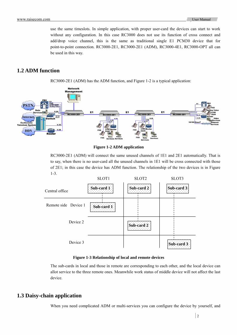
1.2 ADM function
RC3000-2E1 (ADM) has the ADM function, and Figure 1-2 is a typical application:
Figure 1-2 ADM application
RC3000-2E1 (ADM) will connect the same unused channels of 1E1 and 2E1 automatically. That is to say, when there is no user-card all the unused channels in 1E1 will be cross connected with those of 2E1; in this case the device has ADM function. The relationship of the two devices is in Figure 1-3.
Figure 1-3 Relationship of local and remote devices
The sub-cards in local and those in remote are corresponding to each other, and the local device can allot service to the three remote ones. Meanwhile work status of middle device will not affect the last device.
1.3 Daisy-chain application
When you need complicated ADM or multi-services you can configure the device by yourself, and
Central office
Remote side Device 1
Device 2
Device 3
SLOT1 SLOT2 SLOT3
Sub-card 1 Sub-card 2 Sub-card 3
Sub-card 1
Sub-card 2
Sub-card 3

www.raisecom.com User Manual
3
the number of connected RC3000 is alterable.
Figure 1-4 Daisy-chain application
In this application, voice channels in local device can be allotted to remote RC3000 devices and voice channels of remote RC3000 devices can be cross connected too. So multi services access can be realized.
1.4 Point to Multi-Point application (Star mode)
Point-to-multipoint access through RC3000-4E1 in Figure 1-5:
Figure 1-5 Point to Multi-Point application
This application can reduce the number of devices for multi users’ service configuration.
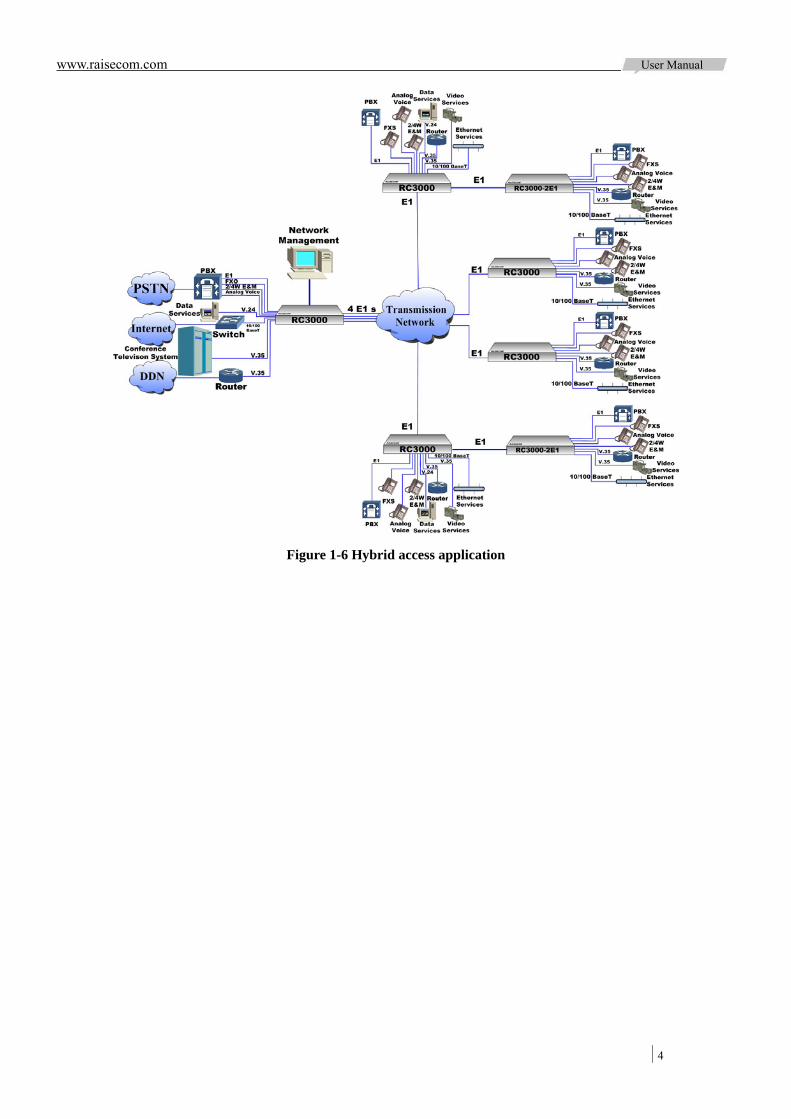
1.5 Hybrid access of star topology and daisy-chain topology
Hybrid access of star topology and chain topology in Figure 1-6:
www.raisecom.com User Manual
4
Figure 1-6 Hybrid access application

www.raisecom.com User Manual
5
Chapter 2 Type of Device and Sub-card
2.1 Device type
Explanation of device type:
RC3000-XXX-XX-XX AC
There are 4 types of up-link card for RC3000:
RC3000-OPT-FE RC3000 up-link card of optical interface
RC3000-OPT-2E1 RC3000 up-link card of optical interface
RC3000-4E1 RC3000 line-board of 4 balanced E1 interfaces
RC3000-2E1 RC3000 line-board of 2 unbalanced E1 interfaces
RC3000-2E1-BL RC3000 line-board of 2 balanced E1 interfaces
RC3000-OPT-FE up-link card has an optical interface and a 100M Ethernet interface; RC3000-OPT-2E1 line-board has an optical interface and 2 E1 ports; RC3000-4E1 line-board has 4 balanced E1 ports; RC3000-2E1 has two CC3 (coaxial cable 3) unbalanced E1 ports, and 2E1 card is in support of ADM function.
For RC3000-OPT-FE the optical module type decides the device type as following table:
Device type Optical module type
RC3000-OPT-FE -S1 Single-mode Dual-fiber 1310, DSC, 0~25Km
RC3000-OPT-FE -S2 Single-mode Dual-fiber 1310, DSC, 10~50Km
RC3000-OPT-FE -S3 Single-mode Dual-fiber 1550, DSC, 15~120Km
RC3000-OPT-FE -SS13 Single-mode Single -fiber Dual-wavelength T1310/R1550, SC, 0~25Km
RC3000-OPT-FE -SS15 Single-mode Single -fiber Dual-wavelength T1550/R1310, SC, 0~25Km
RC3000-OPT-FE -SS23 Single-mode Single -fiber Dual-wavelength T1310/R1550, SC, 10~50Km
RC3000-OPT-FE -SS25 Single-mode Single-fiber Dual-wavelength T1550/R1310, SC, 10~50Km
For power supply type (after the device type), voltage range is AC 100V~240V and DC -36V~-72V.
2.2 Type of sub-card
Explanation of RC3000 user-card type:
Optical interface type of optical line-board
Up-link cardDevice name: multi-service multiplexer
Power supply type: AC or DC
Assistant interface type of optical line-board

www.raisecom.com User Manual
6
RC3000-SUB- D XXX
Sub-cards of RC3000:
Sub-cards type Sub-cards name Channel description
RC3000-SUB-DS FXS user audio sub-card 8 channels, unconfigurable
RC3000-SUB-DO FXO audio relay sub-card 8 channels, unconfigurable
RC3000-SUB-DSO FXS and FXO hybrid voice sub-card 8 channels, unconfigurable
RC3000-SUB-DM2 E&M 2-wire audio relay sub-card 8 channels, unconfigurable
RC3000-SUB-DM4 E&M 4-wire audio relay sub-card 4 channels, unconfigurable
RC3000-SUB-DV35 V35 data sub-card 1 interface, and the time slots of channel is configurable
RC3000-SUB-DV24 V24 data sub-card 4 interface, every interface is configurable in range 64-128k
RC3000-SUB-DETH 10BaseT Ethernet data sub-card 1 interface, and the time slots of channel is configurable
RC3000-SUB-D232 RS232 serial data sub-card 8 channels, unconfigurable
RC3000-SUB-D422 RS422 serial data sub-card 8 channels, unconfigurable
RC3000-SUB-DMT Magneto telephone sub-card 8 channels, unconfigurable
RC3000-SUB-DSR FXS sub-card with polarity
reversible function 8 channels, unconfigurable
RC3000-SUB-D485 RS485 serial data sub-card 8 channels, unconfigurable
RC3000-SUB-DSR(-48V) -48V FXS sub-card with polarity
reversible function 4 channels, unconfigurable
RC3000-SUB-DETHB 10/100BaseT Ethernet data sub-card 1 interface, and the time slots of channel is configurable
RC3000-SUB-DETHX2 Double Ethernet data sub-card 2 interfaces, and the time slots of channel is configurable
RC3000-SUB-DC64K Co direction 64Kdata sub-card 4 channels, unconfigurable
Device name: multi-service multiplexerIdentifier of sub-card
Identifier of sub-card type Name of sub-card
www.raisecom.com User Manual
7
Chapter 3 Technical Specification
3.1 Up-link sub-card
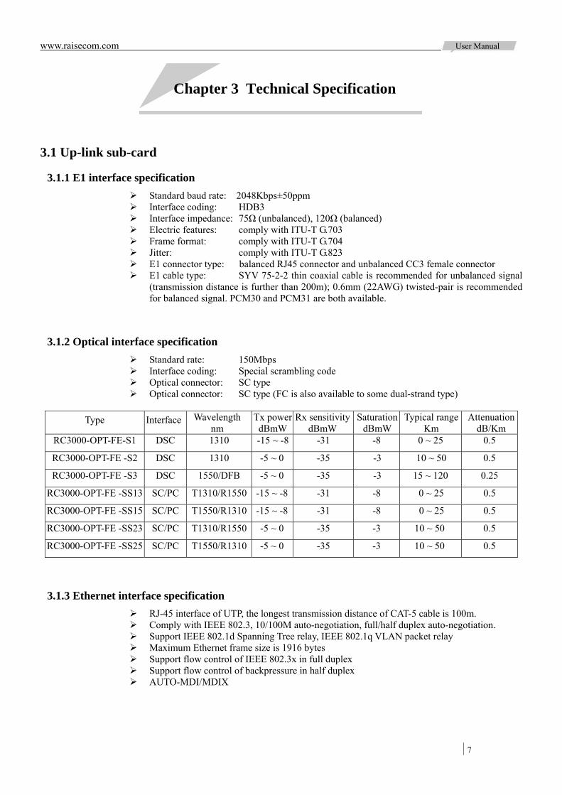
3.1.1 E1 interface specification Standard baud rate: 2048Kbps±50ppm Interface coding: HDB3 Interface impedance: 75Ω (unbalanced), 120Ω (balanced) Electric features: comply with ITU-T G.703 Frame format: comply with ITU-T G.704 Jitter: comply with ITU-T G.823 E1 connector type: balanced RJ45 connector and unbalanced CC3 female connector E1 cable type: SYV 75-2-2 thin coaxial cable is recommended for unbalanced signal
(transmission distance is further than 200m); 0.6mm (22AWG) twisted-pair is recommended for balanced signal. PCM30 and PCM31 are both available.
3.1.2 Optical interface specification Standard rate: 150Mbps Interface coding: Special scrambling code Optical connector: SC type Optical connector: SC type (FC is also available to some dual-strand type)
Type Interface Wavelength
nm Tx powerdBmW
Rx sensitivitydBmW
Saturation dBmW
Typical range Km
AttenuationdB/Km
RC3000-OPT-FE-S1 DSC 1310 -15 ~ -8 -31 -8 0 ~ 25 0.5
RC3000-OPT-FE -S2 DSC 1310 -5 ~ 0 -35 -3 10 ~ 50 0.5
RC3000-OPT-FE -S3 DSC 1550/DFB -5 ~ 0 -35 -3 15 ~ 120 0.25
RC3000-OPT-FE -SS13 SC/PC T1310/R1550 -15 ~ -8 -31 -8 0 ~ 25 0.5
RC3000-OPT-FE -SS15 SC/PC T1550/R1310 -15 ~ -8 -31 -8 0 ~ 25 0.5
RC3000-OPT-FE -SS23 SC/PC T1310/R1550 -5 ~ 0 -35 -3 10 ~ 50 0.5
RC3000-OPT-FE -SS25 SC/PC T1550/R1310 -5 ~ 0 -35 -3 10 ~ 50 0.5
3.1.3 Ethernet interface specification RJ-45 interface of UTP, the longest transmission distance of CAT-5 cable is 100m. Comply with IEEE 802.3, 10/100M auto-negotiation, full/half duplex auto-negotiation. Support IEEE 802.1d Spanning Tree relay, IEEE 802.1q VLAN packet relay Maximum Ethernet frame size is 1916 bytes Support flow control of IEEE 802.3x in full duplex Support flow control of backpressure in half duplex AUTO-MDI/MDIX
www.raisecom.com User Manual
8
3.2 Down-link sub-card
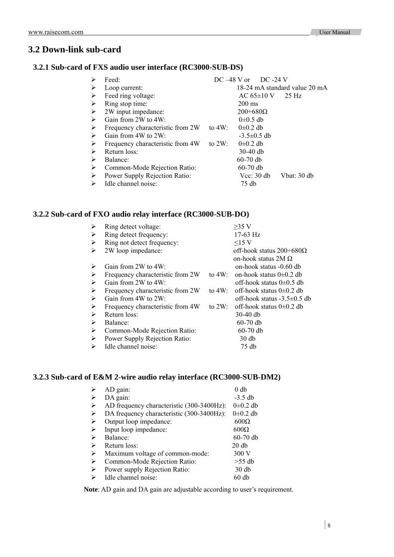
3.2.1 Sub-card of FXS audio user interface (RC3000-SUB-DS) Feed: DC –48 V or DC -24 V Loop current: 18-24 mA standard value 20 mA Feed ring voltage: AC 65±10 V 25 Hz Ring stop time: 200 ms 2W input impedance: 200+680Ω Gain from 2W to 4W: 0±0.5 db Frequency characteristic from 2W to 4W: 0±0.2 db Gain from 4W to 2W: -3.5±0.5 db Frequency characteristic from 4W to 2W: 0±0.2 db Return loss: 30-40 db Balance: 60-70 db Common-Mode Rejection Ratio: 60-70 db Power Supply Rejection Ratio: Vcc: 30 db Vbat: 30 db Idle channel noise: 75 db
3.2.2 Sub-card of FXO audio relay interface (RC3000-SUB-DO) Ring detect voltage: ≥35 V Ring detect frequency: 17-63 Hz Ring not detect frequency: ≤15 V 2W loop impedance: off-hook status 200+680Ω on-hook status 2M Ω Gain from 2W to 4W: on-hook status -0.60 db Frequency characteristic from 2W to 4W: on-hook status 0±0.2 db Gain from 2W to 4W: off-hook status 0±0.5 db Frequency characteristic from 2W to 4W: off-hook status 0±0.2 db Gain from 4W to 2W: off-hook status -3.5±0.5 db Frequency characteristic from 4W to 2W: off-hook status 0±0.2 db Return loss: 30-40 db Balance: 60-70 db Common-Mode Rejection Ratio: 60-70 db Power Supply Rejection Ratio: 30 db Idle channel noise: 75 db
3.2.3 Sub-card of E&M 2-wire audio relay interface (RC3000-SUB-DM2) AD gain: 0 db DA gain: -3.5 db AD frequency characteristic (300-3400Hz): 0±0.2 db DA frequency characteristic (300-3400Hz): 0±0.2 db Output loop impedance: 600Ω Input loop impedance: 600Ω Balance: 60-70 db Return loss: 20 db Maximum voltage of common-mode: 300 V Common-Mode Rejection Ratio: >55 db Power supply Rejection Ratio: 30 db Idle channel noise: 60 db
Note: AD gain and DA gain are adjustable according to user’s requirement.
www.raisecom.com User Manual
9
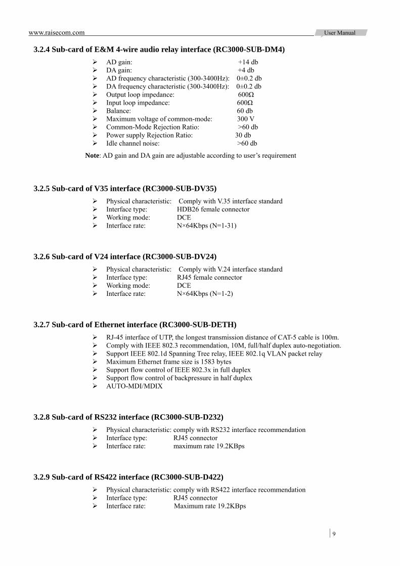
3.2.4 Sub-card of E&M 4-wire audio relay interface (RC3000-SUB-DM4) AD gain: +14 db DA gain: +4 db AD frequency characteristic (300-3400Hz): 0±0.2 db DA frequency characteristic (300-3400Hz): 0±0.2 db Output loop impedance: 600Ω Input loop impedance: 600Ω Balance: 60 db Maximum voltage of common-mode: 300 V Common-Mode Rejection Ratio: >60 db Power supply Rejection Ratio: 30 db Idle channel noise: >60 db
Note: AD gain and DA gain are adjustable according to user’s requirement
3.2.5 Sub-card of V35 interface (RC3000-SUB-DV35) Physical characteristic: Comply with V.35 interface standard Interface type: HDB26 female connector Working mode: DCE Interface rate: N×64Kbps (N=1-31)
3.2.6 Sub-card of V24 interface (RC3000-SUB-DV24) Physical characteristic: Comply with V.24 interface standard Interface type: RJ45 female connector Working mode: DCE Interface rate: N×64Kbps (N=1-2)
3.2.7 Sub-card of Ethernet interface (RC3000-SUB-DETH) RJ-45 interface of UTP, the longest transmission distance of CAT-5 cable is 100m. Comply with IEEE 802.3 recommendation, 10M, full/half duplex auto-negotiation. Support IEEE 802.1d Spanning Tree relay, IEEE 802.1q VLAN packet relay Maximum Ethernet frame size is 1583 bytes Support flow control of IEEE 802.3x in full duplex Support flow control of backpressure in half duplex AUTO-MDI/MDIX
3.2.8 Sub-card of RS232 interface (RC3000-SUB-D232) Physical characteristic: comply with RS232 interface recommendation Interface type: RJ45 connector Interface rate: maximum rate 19.2KBps
3.2.9 Sub-card of RS422 interface (RC3000-SUB-D422) Physical characteristic: comply with RS422 interface recommendation Interface type: RJ45 connector Interface rate: Maximum rate 19.2KBps
www.raisecom.com User Manual
10
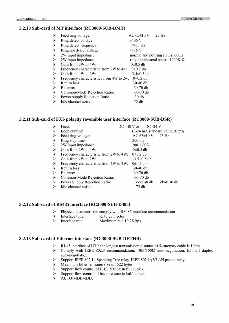
3.2.10 Sub-card of MT interface (RC3000-SUB-DMT) Feed ring voltage: AC 65±10 V 25 Hz Ring detect voltage: ≥35 V Ring detect frequency: 17-63 Hz Ring not detect voltage: ≤15 V 2W input impedance: normal and not ring status: 600Ω 2W input impedance: ring or abnormal status: 1000K Ω Gain from 2W to 4W: 0±0.5 db Frequency characteristic from 2W to 4w: 0±0.2 db Gain from 4W to 2W: -3.5±0.5 db Frequency characteristics from 4W to 2w: 0±0.2 db Return loss: 30-40 db Balance: 60-70 db Common-Mode Rejection Ratio: 60-70 db Power supply Rejection Ratio: 30 db Idle channel noise: 75 db
3.2.11 Sub-card of FXS polarity reversible user interface (RC3000-SUB-DSR) Feed: DC –48 V or DC -24 V Loop current: 18-24 mA standard value 20 mA Feed ring voltage: AC 65±10 V 25 Hz Ring stop time: 200 ms 2W input impedance: 200+680Ω Gain from 2W to 4W: 0±0.5 db Frequency characteristic from 2W to 4W: 0±0.2 db Gain from 4W to 2W: -3.5±0.5 db Frequency characteristic from 4W to 2W: 0±0.2 db Return loss: 30-40 db Balance: 60-70 db Common-Mode Rejection Ratio: 60-70 db Power Supply Rejection Ratio: Vcc: 30 db Vbat: 30 db Idle channel noise: 75 db
3.2.12 Sub-card of RS485 interface (RC3000-SUB-D485) Physical characteristic: comply with RS485 interface recommendation Interface type: RJ45 connector Interface rate: Maximum rate 19.2KBps
3.2.13 Sub-card of Ethernet interface (RC3000-SUB-DETHB) RJ-45 interface of UTP, the longest transmission distance of 5-category cable is 100m. Comply with IEEE 802.3 recommendation, 10M/100M auto-negotiation, full/half duplex
auto-negotiation. Support IEEE 802.1d Spanning Tree relay, IEEE 802.1q VLAN packet relay Maximum Ethernet frame size is 1522 bytes Support flow control of IEEE 802.3x in full duplex Support flow control of backpressure in half duplex AUTO-MDI/MDIX

www.raisecom.com User Manual
11
3.2.14 Sub-card of 64K of co-direction data interface (RC3000-SUB-D485) Physical Properties: in line with ITU-T G.703, G.823 recommendation Interface Type: RJ45 connector Interface impedance: 120Ω (balanced) Symbol Rate: 256K baud Frame Format: Non-Framing Line Coding: co-directional encoding Working way: DCE Transmission: maximum transmission distance of non-shielded CAT-5cable is 300 meters
3.3 Power supply
Input voltage: DC -48V, tolerance range -36V~ -72V AC 220V, tolerance range 100~240V
Module power: general ≤20W, maximum ≤40W
3.4 Ambiance
Temperature:0 ~ 50 Relative humidity: ≤90%(25 no condensing)
3.5 Dimension of chassis
440mm x 44.5mm x 275mm
www.raisecom.com User Manual
12
Chapter 4 Structure and Indicator
4.1 Structure of chassis
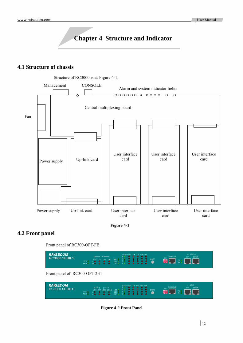
Structure of RC3000 is as Figure 4-1:
4.2 Front panel
Figure 4-2 Front Panel
Power supply Up-link card
Center multiplexer
Front panel of RC300-OPT-FE
Front panel of RC300-OPT-2E1
Alarm and system indicator lights Management
User interface card Up-link card Power supply
User interface card
User interface card
User interface card
User interface card
User interface card
CONSOLE
Fan
Figure 4-1
Central multiplexing board

www.raisecom.com User Manual
13
4.2.1 System indicator SYS (green): Indicates system work status.
Flickering: system works normally.
ON: 1: CPU works abnormal; 2: system configuration error or the following problems:
Sub-card communicates abnormally Temperature sensor works abnormally Fan does not work Time slots configuration error
OFF: CPU works abnormally
PWR (green): OFF indicates system is not powered on.
TX (green): ON indicates serial interface is transmitting data.
RX (green): ON indicates serial interface is receiving data
4.2.2 Up-link sub-card indicators 4E1 (green): ON indicates line-board (up-link card) is 4E1 sub-card
2E1 (green): ON indicates line-board (up-link card) is 2E1 sub-card
OPT (green): ON indicates line-board (up-link card) is optical sub-card
Note: only one of the three lights can be ON, otherwise there is system error.
4.2.3 Optical interface indicator Optical interface alarm indicator lights form a matrix, L and R indicate local and remote, OP (LOS, LOF, E-3, E-6) indicate alarms.
Panel indicators on RC3000-OPT-FE:
L OP LOS (red): Loss of signal at local optical interface
L OP LOF (red): Loss of frame at local optical interface
L OP E-3 (red): Alarm when bit error ratio is more than 10-3/s at local optical interface
L OP E-6 (red): Alarm when bit error ratio is more than 10-6/s at local optical interface
R OP LOS (red): Loss of signal at remote optical interface
R OP LOF (red): Loss of frame at remote optical interface
R OP E-3 (red): Alarm when bit error ratio is more than 10-3/s at remote optical interface
R OP E-6 (red): Alarm when bit error ratio is more than 10-6/s at remote optical interface
Panel indicators on RC3000-OPT-2E1:
L OP LOS (red): Loss of signal at local optical interface
L OP EER (red): Loss of frame, bit error ratio is more than 10-3/s or bit error ratio is more than 10-6/s at local optical interface
L E1 LOS3 (red): Loss of 3E1 signal at local optical interface
www.raisecom.com User Manual
14
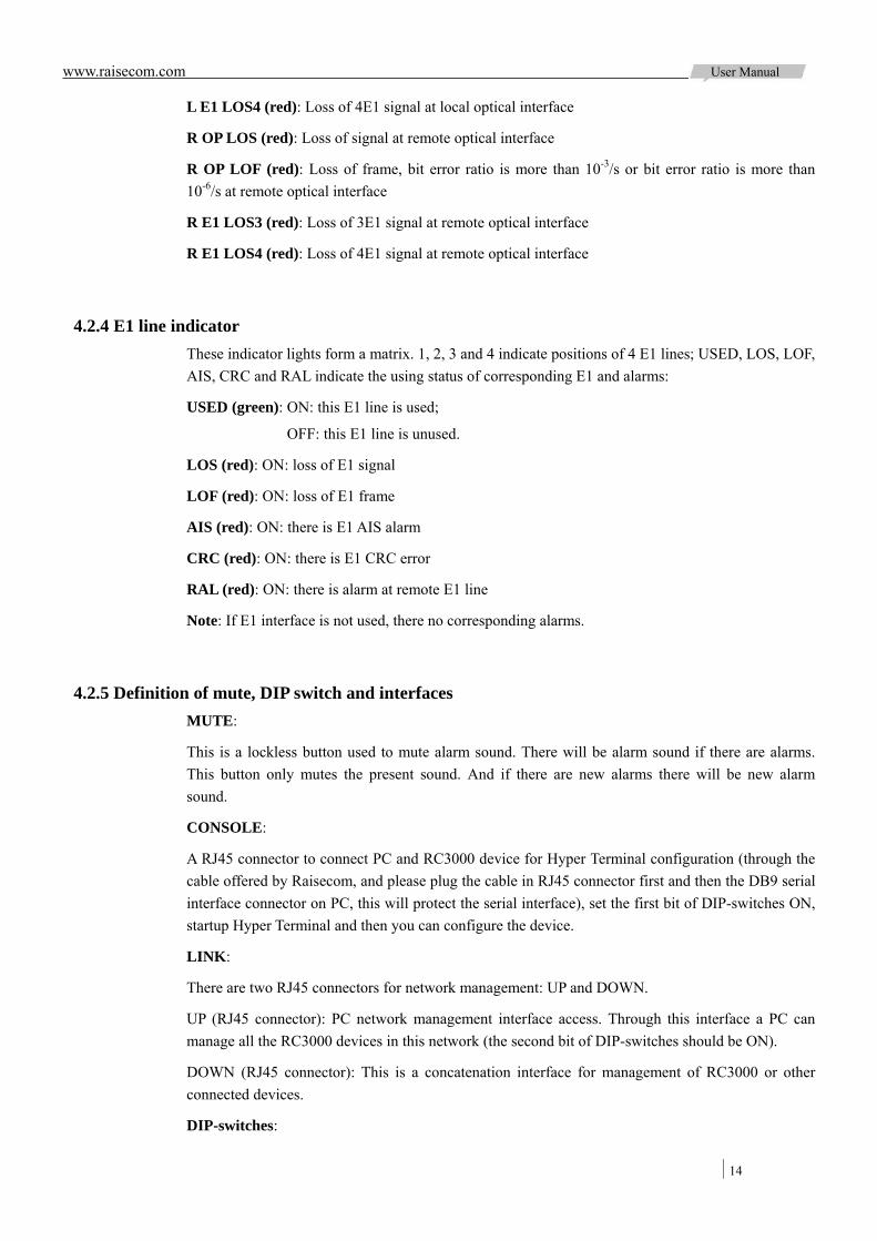
L E1 LOS4 (red): Loss of 4E1 signal at local optical interface
R OP LOS (red): Loss of signal at remote optical interface
R OP LOF (red): Loss of frame, bit error ratio is more than 10-3/s or bit error ratio is more than 10-6/s at remote optical interface
R E1 LOS3 (red): Loss of 3E1 signal at remote optical interface
R E1 LOS4 (red): Loss of 4E1 signal at remote optical interface
4.2.4 E1 line indicator These indicator lights form a matrix. 1, 2, 3 and 4 indicate positions of 4 E1 lines; USED, LOS, LOF, AIS, CRC and RAL indicate the using status of corresponding E1 and alarms:
USED (green): ON: this E1 line is used;
OFF: this E1 line is unused.
LOS (red): ON: loss of E1 signal
LOF (red): ON: loss of E1 frame
AIS (red): ON: there is E1 AIS alarm
CRC (red): ON: there is E1 CRC error
RAL (red): ON: there is alarm at remote E1 line
Note: If E1 interface is not used, there no corresponding alarms.
4.2.5 Definition of mute, DIP switch and interfaces MUTE:
This is a lockless button used to mute alarm sound. There will be alarm sound if there are alarms. This button only mutes the present sound. And if there are new alarms there will be new alarm sound.
CONSOLE:
A RJ45 connector to connect PC and RC3000 device for Hyper Terminal configuration (through the cable offered by Raisecom, and please plug the cable in RJ45 connector first and then the DB9 serial interface connector on PC, this will protect the serial interface), set the first bit of DIP-switches ON, startup Hyper Terminal and then you can configure the device.
LINK:
There are two RJ45 connectors for network management: UP and DOWN.
UP (RJ45 connector): PC network management interface access. Through this interface a PC can manage all the RC3000 devices in this network (the second bit of DIP-switches should be ON).
DOWN (RJ45 connector): This is a concatenation interface for management of RC3000 or other connected devices.
DIP-switches:

www.raisecom.com User Manual
15
The last bit of this DIP switch is standby, and the other three ones are of use.
Bit 1: CONSOLE configuration. Set this bit ON, connect RC3000 with PC through serial interface cable offered by Raisecom, and then you can configure the device by Hyper Terminal. This operation will not affect the whole network management but only shielded that device for a while.
Bit 2: PC network management access. When this RC3000 is network management access device or network management is connected to its LINK UP interface, set this bit ON, and MCU will receive the network management information from LINK UP interface.
Bit 3: Assistant network management channel shielded bit. When the device connected with the E1 interface is not a RC3000 series device, the assistant network management channel may not work. And to make sure of normal network management, set this bit ON, shield assistant channel and than manage the device, in this case LINK DOWN interface is still available for cascade.
Bit 4: This bit is for shifting work mode of device interconnect with device version A. OFF means version B, ON means version A. the device works in mode saved in EEPROM after startup. After it works in normal, software and hardware shifting will be affective based on the last setting and EEPROM will save the last set information.
Note: Only one network management PC is available in a physical network of RC3000s, or the network management cannot manage the devices normally.
4.3 Rear panel
Rear panel view:
4.3.1 Slot of user interface sub-card There are 3 extension slots for user sub-card, from left to right: SLOT1, SLOT2 and SLOT3. After RC3000 voice card upgrades, support to the 10-line at most, so upgrade to the RC3000, an increase of 10-line mode based on the original 8-line mode, user can set the command or HyperTerminal. When channel number of a sub-card is not configurable, this number will be equal or less than 8. In this case, channels for each slot are:
8-line mode 10-line mode
SLOT1: 1-8 channels SLOT1: 1-10 channels
SLOT2: 9-16 channels SLOT1: 11-20 channels
SLOT3: 17-24 channels SLOT1: 21-30 channels
Note:
When lines on card are less than the corresponding mode, it will occupy channel in front, for example: RC3000-SUB-DM4 card itself as four channels, when inserted to the first slot, it will occupy 1-4 channel; when inserted to the second slot, in 8-mode it will occupy 9-12 channel, and in10 mode occupy 11-14 channels.
PWR LINE Figure 4-3
www.raisecom.com User Manual
16
When channel number of a sub-card is configurable, RC3000 will distribute channels for each slot as:
8-line mode 10-line mode
SLOT1: 1-8 channels SLOT1: 1-10 channels
SLOT2: 9-16 channels SLOT1: 11-20 channels
SLOT3: 17-24 channels SLOT1: 21-30 channels
Note: The last slot allocates the number of: timeslots according to the first mode of E1; when PCM30, occupy 17-30 channels; when PCM31, occupy 17-31 channels. The principle of allocating a specific time slot, refer to Function Description behind.
All sub-board support hot-swap and this operation will not affect device work status.
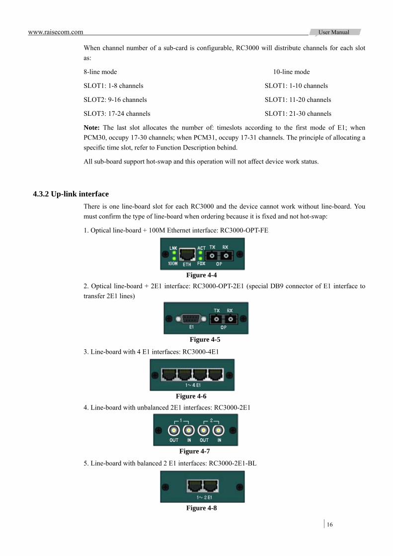
4.3.2 Up-link interface There is one line-board slot for each RC3000 and the device cannot work without line-board. You must confirm the type of line-board when ordering because it is fixed and not hot-swap:
1. Optical line-board + 100M Ethernet interface: RC3000-OPT-FE
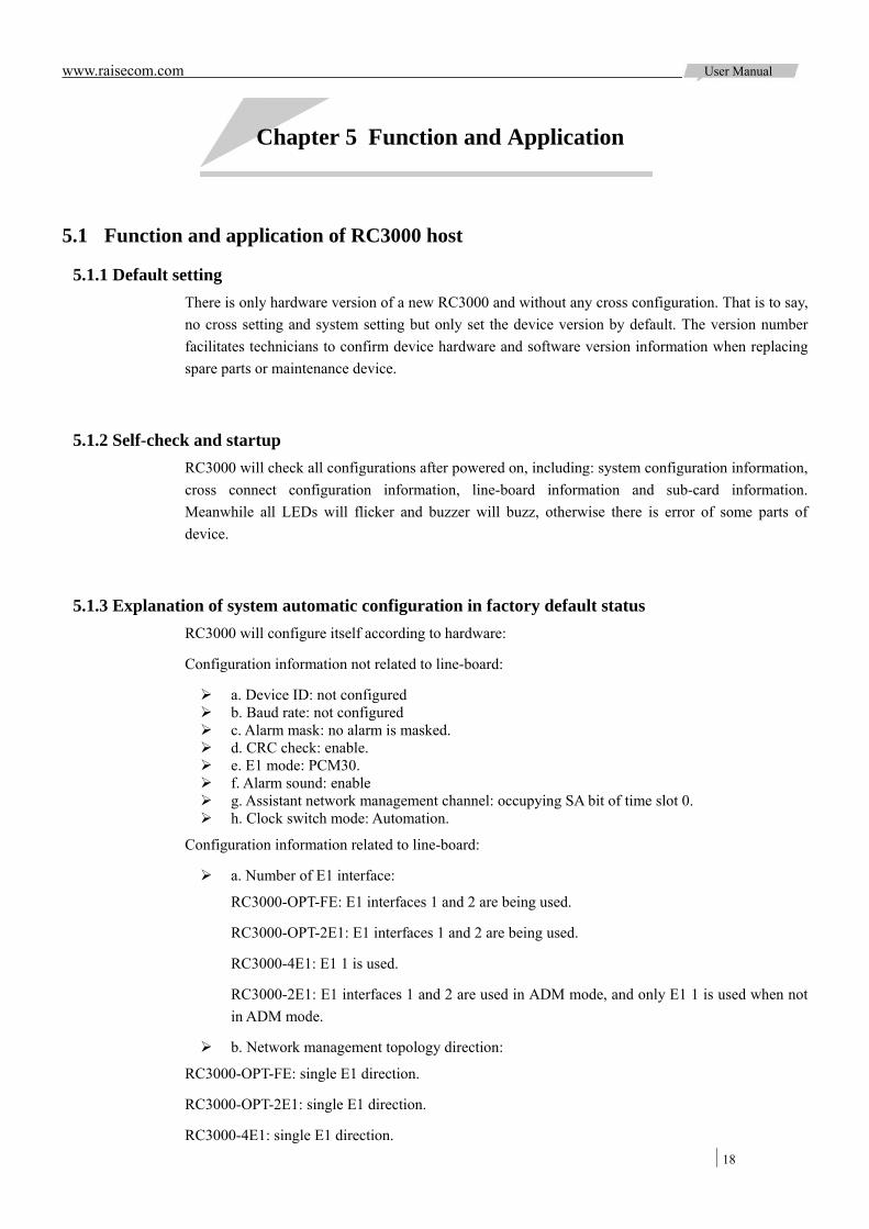
2. Optical line-board + 2E1 interface: RC3000-OPT-2E1 (special DB9 connector of E1 interface to transfer 2E1 lines)
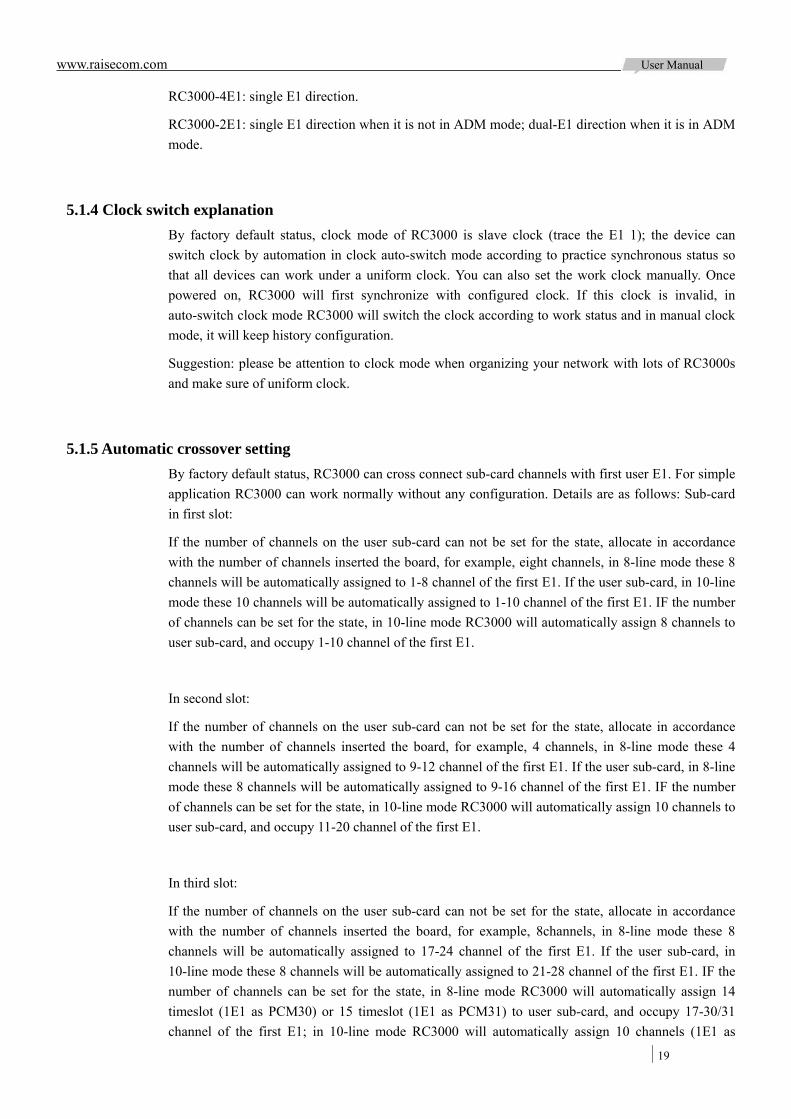
3. Line-board with 4 E1 interfaces: RC3000-4E1
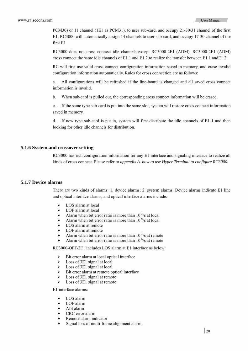
4. Line-board with unbalanced 2E1 interfaces: RC3000-2E1
5. Line-board with balanced 2 E1 interfaces: RC3000-2E1-BL
Figure 4-4
Figure 4-5
Figure 4-6
Figure 4-7
Figure 4-8

www.raisecom.com User Manual
17
4.3.3 Power supply interface There are two kinds of power supply interface for AC and DC, voltage range is: AC 100V ~ 240V, DC –36V ~ -72V.
Note: please make sure of grounding protection for safety when using AC power supply.
www.raisecom.com User Manual
18
Chapter 5 Function and Application
5.1 Function and application of RC3000 host
5.1.1 Default setting There is only hardware version of a new RC3000 and without any cross configuration. That is to say, no cross setting and system setting but only set the device version by default. The version number facilitates technicians to confirm device hardware and software version information when replacing spare parts or maintenance device.
5.1.2 Self-check and startup RC3000 will check all configurations after powered on, including: system configuration information, cross connect configuration information, line-board information and sub-card information. Meanwhile all LEDs will flicker and buzzer will buzz, otherwise there is error of some parts of device.
5.1.3 Explanation of system automatic configuration in factory default status RC3000 will configure itself according to hardware:
Configuration information not related to line-board:
a. Device ID: not configured b. Baud rate: not configured c. Alarm mask: no alarm is masked. d. CRC check: enable. e. E1 mode: PCM30. f. Alarm sound: enable g. Assistant network management channel: occupying SA bit of time slot 0. h. Clock switch mode: Automation.
Configuration information related to line-board:
a. Number of E1 interface:
RC3000-OPT-FE: E1 interfaces 1 and 2 are being used.
RC3000-OPT-2E1: E1 interfaces 1 and 2 are being used.
RC3000-4E1: E1 1 is used.
RC3000-2E1: E1 interfaces 1 and 2 are used in ADM mode, and only E1 1 is used when not in ADM mode.
b. Network management topology direction:
RC3000-OPT-FE: single E1 direction.
RC3000-OPT-2E1: single E1 direction.
RC3000-4E1: single E1 direction.
www.raisecom.com User Manual
19
RC3000-4E1: single E1 direction.
RC3000-2E1: single E1 direction when it is not in ADM mode; dual-E1 direction when it is in ADM mode.
5.1.4 Clock switch explanation By factory default status, clock mode of RC3000 is slave clock (trace the E1 1); the device can switch clock by automation in clock auto-switch mode according to practice synchronous status so that all devices can work under a uniform clock. You can also set the work clock manually. Once powered on, RC3000 will first synchronize with configured clock. If this clock is invalid, in auto-switch clock mode RC3000 will switch the clock according to work status and in manual clock mode, it will keep history configuration.
Suggestion: please be attention to clock mode when organizing your network with lots of RC3000s and make sure of uniform clock.
5.1.5 Automatic crossover setting By factory default status, RC3000 can cross connect sub-card channels with first user E1. For simple application RC3000 can work normally without any configuration. Details are as follows: Sub-card in first slot:
If the number of channels on the user sub-card can not be set for the state, allocate in accordance with the number of channels inserted the board, for example, eight channels, in 8-line mode these 8 channels will be automatically assigned to 1-8 channel of the first E1. If the user sub-card, in 10-line mode these 10 channels will be automatically assigned to 1-10 channel of the first E1. IF the number of channels can be set for the state, in 10-line mode RC3000 will automatically assign 8 channels to user sub-card, and occupy 1-10 channel of the first E1.
In second slot:
If the number of channels on the user sub-card can not be set for the state, allocate in accordance with the number of channels inserted the board, for example, 4 channels, in 8-line mode these 4 channels will be automatically assigned to 9-12 channel of the first E1. If the user sub-card, in 8-line mode these 8 channels will be automatically assigned to 9-16 channel of the first E1. IF the number of channels can be set for the state, in 10-line mode RC3000 will automatically assign 10 channels to user sub-card, and occupy 11-20 channel of the first E1.
In third slot:
If the number of channels on the user sub-card can not be set for the state, allocate in accordance with the number of channels inserted the board, for example, 8channels, in 8-line mode these 8 channels will be automatically assigned to 17-24 channel of the first E1. If the user sub-card, in 10-line mode these 8 channels will be automatically assigned to 21-28 channel of the first E1. IF the number of channels can be set for the state, in 8-line mode RC3000 will automatically assign 14 timeslot (1E1 as PCM30) or 15 timeslot (1E1 as PCM31) to user sub-card, and occupy 17-30/31 channel of the first E1; in 10-line mode RC3000 will automatically assign 10 channels (1E1 as
www.raisecom.com User Manual
20
PCM30) or 11 channel (1E1 as PCM31), to user sub-card, and occupy 21-30/31 channel of the first E1. RC3000 will automatically assign 14 channels to user sub-card, and occupy 17-30 channel of the first E1
RC3000 does not cross connect idle channels except RC3000-2E1 (ADM). RC3000-2E1 (ADM) cross connect the same idle channels of E1 1 and E1 2 to realize the transfer between E1 1 andE1 2.
RC will first use valid cross connect configuration information saved in memory, and erase invalid configuration information automatically. Rules for cross connection are as follows:
a. All configurations will be refreshed if the line-board is changed and all saved cross connect information is invalid.
b. When sub-card is pulled out, the corresponding cross connect information will be erased.
c. If the same type sub-card is put into the same slot, system will restore cross connect information saved in memory.
d. If new type sub-card is put in, system will first distribute the idle channels of E1 1 and then looking for other idle channels for distribution.
5.1.6 System and crossover setting RC3000 has rich configuration information for any E1 interface and signaling interface to realize all kinds of cross connect. Please refer to appendix A. how to use Hyper Terminal to configure RC3000.
5.1.7 Device alarms There are two kinds of alarms: 1. device alarms; 2. system alarms. Device alarms indicate E1 line and optical interface alarms, and optical interface alarms include:
LOS alarm at local LOF alarm at local Alarm when bit error ratio is more than 10-3/s at local Alarm when bit error ratio is more than 10-6/s at local LOS alarm at remote LOF alarm at remote Alarm when bit error ratio is more than 10-3/s at remote Alarm when bit error ratio is more than 10-6/s at remote
RC3000-OPT-2E1 includes LOS alarm at E1 interface as below:
Bit error alarm at local optical interface Loss of 3E1 signal at local Loss of 3E1 signal at local Bit error alarm at remote optical interface Loss of 3E1 signal at remote Loss of 3E1 signal at remote
E1 interface alarms:
LOS alarm LOF alarm AIS alarm CRC error alarm Remote alarm indicator Signal loss of multi-frame alignment alarm

www.raisecom.com User Manual
21
CRC loss of multi-frame alignment alarm
There is no alarm f and g on device panel and you can get these alarm information through network management or Hyper Terminal.
There are system alarms when RC3000 cannot work normally, including:
Status of data storage (there are four kinds of data saved in memory): the main board, E1 module, 2M module and device version.
Communication status of sub-card: whether the main board communicate with the three sub-cards successfully
Communication status of line-board Work status of temperature converter Work status of fan Channel configuration information of each sub-card confliction
5.1.8 Network management channel RC3000 has both assistant network management channel and network management concatenation function. Through assistant network management channel local PC can manage remote devices, local and remote network management channel connection can be realized through LINK UP and LINK DOWN interfaces on RC3000, so one network management PC can manage all RC3000s in different networks. The following is exact explanations:
a. Assistant network management channel:
Through assistant network management channel all RC3000s in one network can be managed as in Figure 5-1:
In this topology the lines between each RC3000 are assistant network management channels, and for normal network management there must be network management topology configuration as follows:
RC3000 A: dual-E1 channel direction RC3000 B: single E1 channel direction
RC3000 C: single E1 channel direction RC3000 D: four E1 channel direction
RC3000 E: single E1 channel direction RC3000 F: single E1 channel direction
Rules for network management topology: The number of network management channels decides the number of E1 direction, and configuration of E1 direction must start from 1 E1.
b. Network management concatenation:
Figure 5-1
A
1E1 1E1 1
2E1
2E
1
1E12
3E1 1 E 1
4E1
B E
D
C
F
1E1 1
1 2E1
3E1 3
4E1 4 1E1 1 1E1
2E1 2

www.raisecom.com User Manual
22
Local and remote network management channel connection can be realized through LINK UP and LINK DOWN interfaces on RC3000 as in Figure 5-2:
There are three RC3000 networks: RC3000A and RC3000B connected through E1 cable, RC3000C and RC3000D connected through E1 cable, RC3000E and RC3000F connected through E1 cable; connect RC3000A and RC3000C through concatenation cable, RC3000B and RC3000E through concatenation cable, and set the second bits of A, C, E’s DIP-switches ON, then local and remote network management channel connection can be realized through LINK UP and LINK DOWN interfaces.
5.1.9 Port definition a. CONSOLE definition of Hyper Terminal:
CONSOLE interface for Hyper Terminal is RJ45 interface and standard RS232 level:
Signaling and Pin definition of CONSOLE port:
Pin number Signal Explanation
3 RXD Rx of RC3000
7 TXD Tx of RC3000
4,8 GND Ground of RC3000
b.LINK UP network management interface definition:
Network management interface LINK UP is RJ45 interface and standard RS232 level:
Signaling and Pin definition of LINK UP interface:
Pin number Signal Explanation
3 RXD Rx of RC3000
7 TXD Tx of RC3000
4,8 GND Ground of RC3000
c. LINK DOWN network management interface definition:
Network management interface LINK DOWN is RJ45 interface and standard RS232 level:
1E1
Figure 5-2
A
F
D
B E 1E1 1 1E1
1E1
1E1
LINKDOWN
1E1 1E1
LINKUP
LINKDOWN
C
LINKUP
2
1
1 2 3 4 5 6 7 8
Figure 5-3
www.raisecom.com User Manual
23
Signaling and Pin definition of LINK DOWN interface:
Pin number Signal Explanation
3 TXD Rx of RC3000
7 RXD Tx of RC3000
4,8 GND Ground of RC3000
d. Definition of balanced RC3000-4E1 E1 interface:
Balanced E1 interface is RJ45 interface, and the Signaling and Pin definition are:
Pin number Signal Explanation
1 OUT+ Positive Tx of balanced E1 interface
2 OUT- Negative Tx of balanced E1 interface
4 IN+ Positive Rx of balanced E1 interface
5 IN- Negative Rx of balanced E1 interface
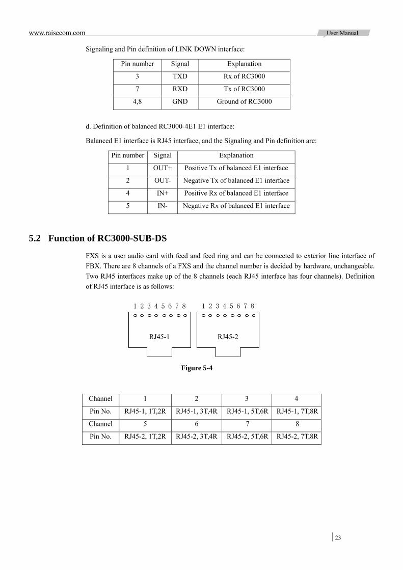
5.2 Function of RC3000-SUB-DS
FXS is a user audio card with feed and feed ring and can be connected to exterior line interface of FBX. There are 8 channels of a FXS and the channel number is decided by hardware, unchangeable. Two RJ45 interfaces make up of the 8 channels (each RJ45 interface has four channels). Definition of RJ45 interface is as follows:
Channel 1 2 3 4
Pin No. RJ45-1, 1T,2R RJ45-1, 3T,4R RJ45-1, 5T,6R RJ45-1, 7T,8R
Channel 5 6 7 8
Pin No. RJ45-2, 1T,2R RJ45-2, 3T,4R RJ45-2, 5T,6R RJ45-2, 7T,8R
1 2 3 4 5 6 7 8 1 2 3 4 5 6 7 8
Figure 5-4
RJ45-1 RJ45-2
www.raisecom.com User Manual
24
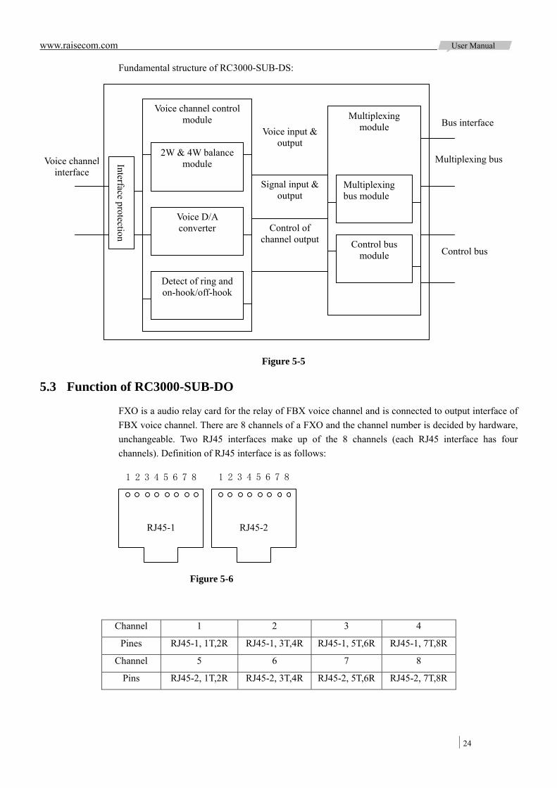
Fundamental structure of RC3000-SUB-DS:
5.3 Function of RC3000-SUB-DO
FXO is a audio relay card for the relay of FBX voice channel and is connected to output interface of FBX voice channel. There are 8 channels of a FXO and the channel number is decided by hardware, unchangeable. Two RJ45 interfaces make up of the 8 channels (each RJ45 interface has four channels). Definition of RJ45 interface is as follows:
Channel 1 2 3 4
Pines RJ45-1, 1T,2R RJ45-1, 3T,4R RJ45-1, 5T,6R RJ45-1, 7T,8R
Channel 5 6 7 8
Pins RJ45-2, 1T,2R RJ45-2, 3T,4R RJ45-2, 5T,6R RJ45-2, 7T,8R
1 2 3 4 5 6 7 8 1 2 3 4 5 6 7 8
Figure 5-6
RJ45-1 RJ45-2
Multiplexing bus module
Figure 5-5
Voice channelinterface
Voice channel control module Multiplexing
module
Control bus module
Voice input & output
Control of channel output
Interface protection
Signal input & output
2W & 4W balance module
Voice D/A converter
Detect of ring and on-hook/off-hook
Bus interface
Multiplexing bus
Control bus
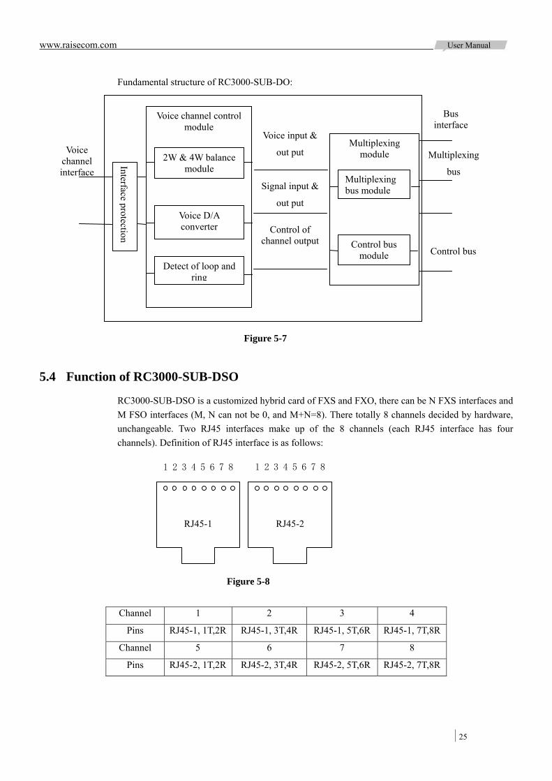
www.raisecom.com User Manual
25
Fundamental structure of RC3000-SUB-DO:
5.4 Function of RC3000-SUB-DSO
RC3000-SUB-DSO is a customized hybrid card of FXS and FXO, there can be N FXS interfaces and M FSO interfaces (M, N can not be 0, and M+N=8). There totally 8 channels decided by hardware, unchangeable. Two RJ45 interfaces make up of the 8 channels (each RJ45 interface has four channels). Definition of RJ45 interface is as follows:
Channel 1 2 3 4
Pins RJ45-1, 1T,2R RJ45-1, 3T,4R RJ45-1, 5T,6R RJ45-1, 7T,8R
Channel 5 6 7 8
Pins RJ45-2, 1T,2R RJ45-2, 3T,4R RJ45-2, 5T,6R RJ45-2, 7T,8R
Multiplexing
bus
Bus interface
Voice channel control module
Multiplexing module
Control bus
Multiplexing bus module
Control bus module
Voice input &
out put
Signal input &
out put
Control of channel output
2W & 4W balance module
Voice D/A converter
Detect of loop and ring
Voice channel interface
Interface protection
Figure 5-7
1 2 3 4 5 6 7 8 1 2 3 4 5 6 7 8
Figure 5-8
RJ45-1 RJ45-2
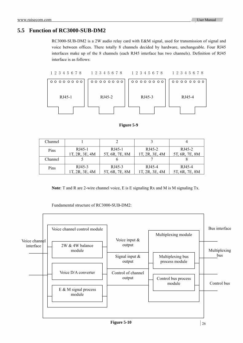
www.raisecom.com User Manual
26
5.5 Function of RC3000-SUB-DM2
RC3000-SUB-DM2 is a 2W audio relay card with E&M signal, used for transmission of signal and voice between offices. There totally 8 channels decided by hardware, unchangeable. Four RJ45 interfaces make up of the 8 channels (each RJ45 interface has two channels). Definition of RJ45 interface is as follows:
Channel 1 2 3 4
Pins RJ45-1 1T, 2R, 3E, 4M
RJ45-1 5T, 6R, 7E, 8M
RJ45-2 1T, 2R, 3E, 4M
RJ45-2 5T, 6R, 7E, 8M
Channel 5 6 7 8
Pins RJ45-3 1T, 2R, 3E, 4M
RJ45-3 5T, 6R, 7E, 8M
RJ45-4 1T, 2R, 3E, 4M
RJ45-4 5T, 6R, 7E, 8M
Note: T and R are 2-wire channel voice, E is E signaling Rx and M is M signaling Tx.
Fundamental structure of RC3000-SUB-DM2:
1 2 3 4 5 6 7 8 1 2 3 4 5 6 7 8
RJ45-1 RJ45-2
1 2 3 4 5 6 7 8 1 2 3 4 5 6 7 8
Figure 5-9
RJ45-3 RJ45-4
Voice channel control module Multiplexing module
Voice channel interface
Bus interface
Multiplexing
bus
Control bus
Multiplexing bus process module
Control bus process module
Voice input & output
Signal input & output
Control of channel output
2W & 4W balance module
Voice D/A converter
E & M signal process module
Figure 5-10

www.raisecom.com User Manual
27
5.6 Function of RC3000-SUB-DM4
RC3000-SUB-DM4 is a 4-wire audio relay card with E&M signal, used for signal and voice transmission between offices. There totally 4 channels decided by hardware, unchangeable. Four RJ45 interfaces make up of the 4 channels (each RJ45 interface has one channel). Definition of RJ45 interface is as follows:
Channel 1 2 3 4
Pins RJ45-1
1TX-T, 2TX-R 3RX-T, 4RX-R
6E, 7M
RJ45-2 1TX-T, 2TX-R 3RX-T, 4RX-R
6E, 7M
RJ45-3 1TX-T, 2TX-R 3RX-T, 4RX-R
6E, 7M
RJ45-4 1TX-T, 2TX-R 3RX-T, 4RX-R
6E, 7M
Note: 1TX-T and 2TX-R are 2-wire voice Tx, 3RX-T and 4RX-T-R are 2-wire voice Rx, 6E is E signaling Rx and 7M is M signaling Tx.
Interface types of RC3000-SUB-DM4 and RC3000-SUB-DM2 cards are both TYPE V.
Fundamental structure of RC3000-SUB-DM4:
1 2 3 4 5 6 7 8 1 2 3 4 5 6 7 8
RJ45-1 RJ45-2
1 2 3 4 5 6 7 8 1 2 3 4 5 6 7 8
Figure 5-11
RJ45-3 RJ45-4
Voice channel control module
Multiplexing module Voice channel interface
Bus interface
Multiplexing bus
Control bus
Multiplexing bus process module
Control bus process module
Voice input & output
Signal input &
output
Control of channel output
Voice D/A converter
E & M signal process module
Figure 5-12
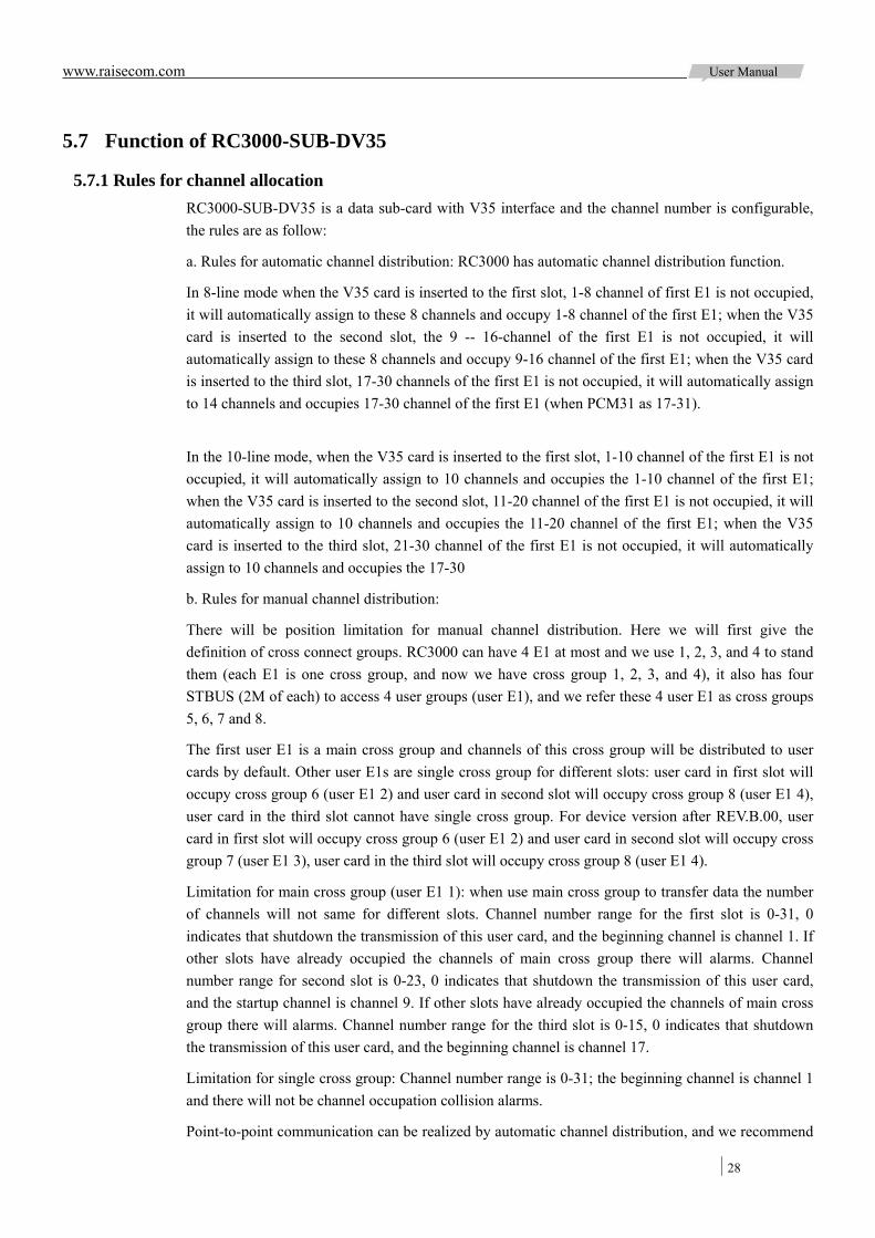
www.raisecom.com User Manual
28
5.7 Function of RC3000-SUB-DV35
5.7.1 Rules for channel allocation RC3000-SUB-DV35 is a data sub-card with V35 interface and the channel number is configurable, the rules are as follow:
a. Rules for automatic channel distribution: RC3000 has automatic channel distribution function.
In 8-line mode when the V35 card is inserted to the first slot, 1-8 channel of first E1 is not occupied, it will automatically assign to these 8 channels and occupy 1-8 channel of the first E1; when the V35 card is inserted to the second slot, the 9 -- 16-channel of the first E1 is not occupied, it will automatically assign to these 8 channels and occupy 9-16 channel of the first E1; when the V35 card is inserted to the third slot, 17-30 channels of the first E1 is not occupied, it will automatically assign to 14 channels and occupies 17-30 channel of the first E1 (when PCM31 as 17-31).
In the 10-line mode, when the V35 card is inserted to the first slot, 1-10 channel of the first E1 is not occupied, it will automatically assign to 10 channels and occupies the 1-10 channel of the first E1; when the V35 card is inserted to the second slot, 11-20 channel of the first E1 is not occupied, it will automatically assign to 10 channels and occupies the 11-20 channel of the first E1; when the V35 card is inserted to the third slot, 21-30 channel of the first E1 is not occupied, it will automatically assign to 10 channels and occupies the 17-30
b. Rules for manual channel distribution:
There will be position limitation for manual channel distribution. Here we will first give the definition of cross connect groups. RC3000 can have 4 E1 at most and we use 1, 2, 3, and 4 to stand them (each E1 is one cross group, and now we have cross group 1, 2, 3, and 4), it also has four STBUS (2M of each) to access 4 user groups (user E1), and we refer these 4 user E1 as cross groups 5, 6, 7 and 8.
The first user E1 is a main cross group and channels of this cross group will be distributed to user cards by default. Other user E1s are single cross group for different slots: user card in first slot will occupy cross group 6 (user E1 2) and user card in second slot will occupy cross group 8 (user E1 4), user card in the third slot cannot have single cross group. For device version after REV.B.00, user card in first slot will occupy cross group 6 (user E1 2) and user card in second slot will occupy cross group 7 (user E1 3), user card in the third slot will occupy cross group 8 (user E1 4).
Limitation for main cross group (user E1 1): when use main cross group to transfer data the number of channels will not same for different slots. Channel number range for the first slot is 0-31, 0 indicates that shutdown the transmission of this user card, and the beginning channel is channel 1. If other slots have already occupied the channels of main cross group there will alarms. Channel number range for second slot is 0-23, 0 indicates that shutdown the transmission of this user card, and the startup channel is channel 9. If other slots have already occupied the channels of main cross group there will alarms. Channel number range for the third slot is 0-15, 0 indicates that shutdown the transmission of this user card, and the beginning channel is channel 17.
Limitation for single cross group: Channel number range is 0-31; the beginning channel is channel 1 and there will not be channel occupation collision alarms.
Point-to-point communication can be realized by automatic channel distribution, and we recommend
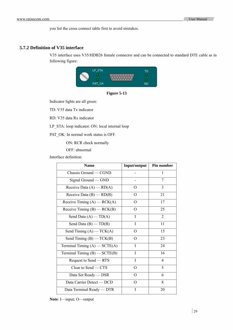
www.raisecom.com User Manual
29
you list the cross connect table first to avoid mistakes.
5.7.2 Definition of V35 interface V35 interface uses V35/HDB26 female connector and can be connected to standard DTE cable as in following figure:
Figure 5-13
Indicator lights are all green:
TD: V35 data Tx indicator
RD: V35 data Rx indicator
LP_STA: loop indicator. ON: local internal loop
PAT_OK: In normal work status is OFF.
ON: RCR check normally
OFF: abnormal
Interface definition:
Name Input/output Pin number
Chassis Ground — CGND - 1
Signal Ground — GND - 7
Receive Data (A) — RD(A) O 3
Receive Data (B) — RD(B) O 21
Receive Timing (A) — RCK(A) O 17
Receive Timing (B) — RCK(B) O 25
Send Data (A) — TD(A) I 2
Send Data (B) — TD(B) I 11
Send Timing (A) — TCK(A) O 15
Send Timing (B) — TCK(B) O 23
Terminal Timing (A) — SCTE(A) I 24
Terminal Timing (B) — SCTE(B) I 16
Request to Send — RTS I 4
Clear to Send — CTS O 5
Data Set Ready — DSR O 6
Data Carrier Detect — DCD O 8
Data Terminal Ready — DTR I 20
Note: I—input; O—output
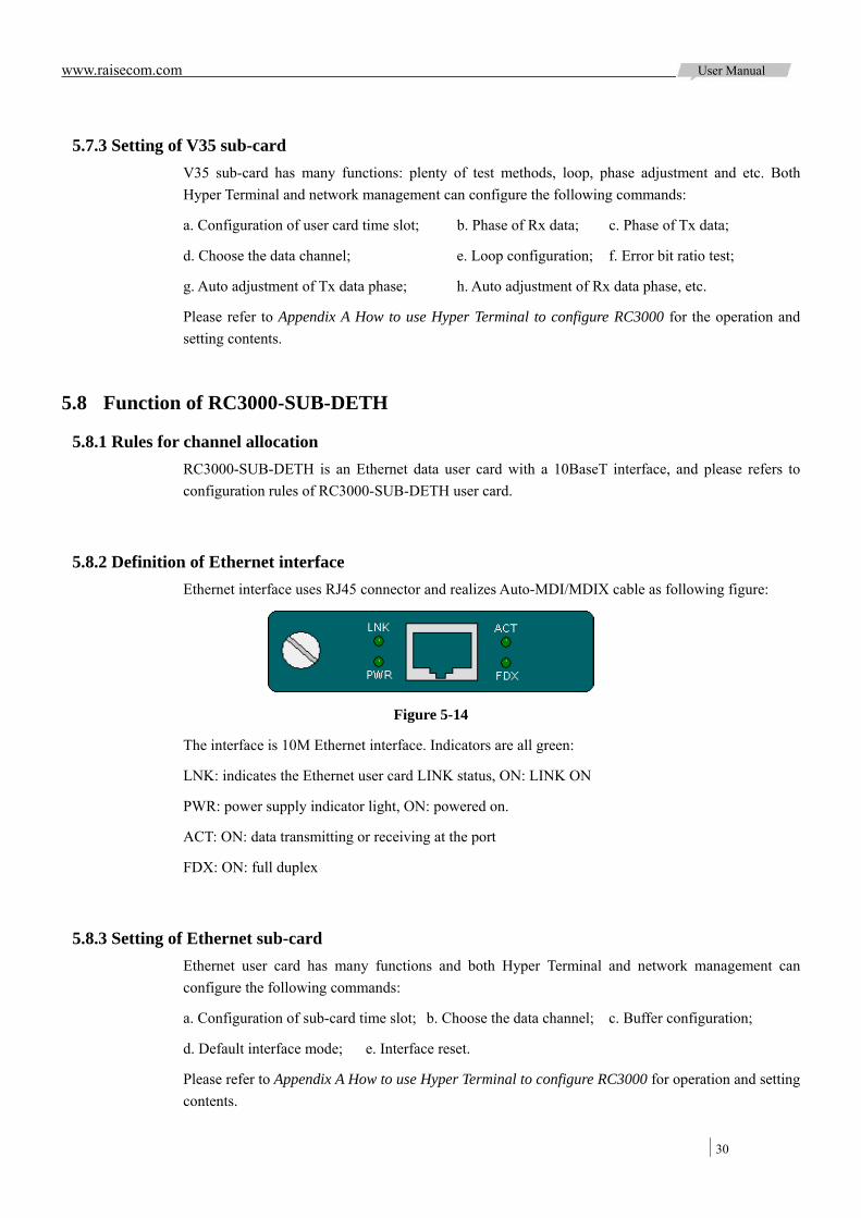
www.raisecom.com User Manual
30
5.7.3 Setting of V35 sub-card V35 sub-card has many functions: plenty of test methods, loop, phase adjustment and etc. Both Hyper Terminal and network management can configure the following commands:
a. Configuration of user card time slot; b. Phase of Rx data; c. Phase of Tx data;
d. Choose the data channel; e. Loop configuration; f. Error bit ratio test;
g. Auto adjustment of Tx data phase; h. Auto adjustment of Rx data phase, etc.
Please refer to Appendix A How to use Hyper Terminal to configure RC3000 for the operation and setting contents.
5.8 Function of RC3000-SUB-DETH
5.8.1 Rules for channel allocation RC3000-SUB-DETH is an Ethernet data user card with a 10BaseT interface, and please refers to configuration rules of RC3000-SUB-DETH user card.
5.8.2 Definition of Ethernet interface Ethernet interface uses RJ45 connector and realizes Auto-MDI/MDIX cable as following figure:
Figure 5-14
The interface is 10M Ethernet interface. Indicators are all green:
LNK: indicates the Ethernet user card LINK status, ON: LINK ON
PWR: power supply indicator light, ON: powered on.
ACT: ON: data transmitting or receiving at the port
FDX: ON: full duplex
5.8.3 Setting of Ethernet sub-card Ethernet user card has many functions and both Hyper Terminal and network management can configure the following commands:
a. Configuration of sub-card time slot; b. Choose the data channel; c. Buffer configuration;
d. Default interface mode; e. Interface reset.
Please refer to Appendix A How to use Hyper Terminal to configure RC3000 for operation and setting contents.
www.raisecom.com User Manual
31
5.9 Function of RC3000-SUB-D232
RC3000-SUB-D232 serial data sub-card has standard RS232 interface. There are 8 channels which is decided by hardware, unchangeable. Four RJ45 connectors make up of the 8 channels and each RJ45 connector has two channels. And the definition of each interface is as follows:
Channel 1 2 3 4
Pins RJ45-1 2RX,3TX,1,4GND
RJ45-1 6RX,7TX,5,8GND
RJ45-2 2RX,3TX,1,4GND
RJ45-2 6RX,7TX,5,8GND
Channel 5 6 7 8
Pins RJ45-3 2RX,3TX,1,4GND
RJ45-3 6RX,7TX,5,8GND
RJ45-4 2RX,3TX,1,4GND
RJ45-4 6RX,7TX,5,8GND
Note: 2RX is the input of RS232 Rx data, 3TX is the output of Tx data and 1, 4GND are the ground. Here we want to explain the grounding rules: there are two grounding conductors, one is signal grounding and the other one is chassis grounding connects to DB9 or DB15. Please connect the RJ45 connector of RS232 first and then DB interface of other device when connect RS232 with other device (both powered on), this can make sure of grounding protection to avoid destroy of RS232 serial interface.
5.9.1 Interface reference of RS232 Interface definition of general connector.
a. DB9 definition:
1: Carrier Detect (DCD), 2: Receive Data (RXD), 3: Transmitting Data (TXD),
4: Data Terminal Ready (DTR), 5: Signal Ground (SG), 6: Data Ready (DSR),
7: Request Transmitting (RTS), 8: Clear Transmitting (CTS), 9: Ring Indication (RI).
b. DB25 definition:
1: Not using, 2: Transmitting Data (TXD), 3: Receiving Data (RXD),
4: Request Transmitting (RTS), 5: Clear Transmitting (CTS), 6: Data Ready (DSR),
7: Signal Ground (SG), 8: Carrier Detect (DCD), 9-19: Not using,
20: Data Terminal Ready (DTR), 21: Not using, 22: Ring Indication (RI),
23-25: Not using.
Definition of DB9 and DB25 as well as dealing with connection of RC3000-SUB-D232 sub-card:
DB9 2 3 5 1, 4, 6 7, 8
1 2 3 4 5 6 7 8 1 2 3 4 5 6 7 8
RJ45-1 RJ45-2
1 2 3 4 5 6 7 8 1 2 3 4 5 6 7 8
Figure 5-14
RJ45-3 RJ45-4

www.raisecom.com User Manual
32
DB25 3 2 7 6, 8, 20 4, 5
Signal name TXD RXD Ground Internal connection Internal connection
Note: The above connection mode is just for users’ reference.
5.10 Function of RC3000-SUB-D422
RC3000-SUB-D422 user card has standard RS422 interface. There are 8 channels which are decided by hardware, unchangeable. Four RJ45 connectors make up of the 8 channels and each RJ45 connector has two channels. And the definition of each interface is as follows:
Channel 1 2 3 4
Pins RJ45-1 1RA,2RB,3TA,4TB
RJ45-1 5RA,6RB,7TA,8TB
RJ45-2 1RA,2RB,3TA,4TB
RJ45-2 5RA,6RB,7TA,8TB
Channel 5 6 7 8
Pins RJ45-3 1RA,2RB,3TA,4TB
RJ45-3 5RA,6RB,7TA,8TB
RJ45-4 1RA,2RB,3TA,4TB
RJ45-4 5RA,6RB,7TA,8TB
Note: 1RA is the positive input of RS422 Rx data, 2RB is the negative input of RS422 Rx data, 3TA is the positive output of RS422 Tx data and 4TB is the negative output of RS422 Tx data. RC3000-SUB-D422 user card has static protection and the serial interface will not be destroyed. In application, please connect the cable first and then plug the user card into RC3000 slot.
5.11 Function of RC3000-SUB-DMT
RC3000-SUB-DMT is a magneto telephone sub-card and can transmit magneto telephone calls (hot-wire magneto telephone). There are 8 channels which are decided by hardware, unchangeable. Two RJ45 connectors make up of the 8 channels and each RJ45 connector has four channels. And the definition of each interface is as follows:
1 2 3 4 5 6 7 8 1 2 3 4 5 6 7 8
Figure 5-16
RJ45-1 RJ45-2
1 2 3 4 5 6 7 8 1 2 3 4 5 6 7 8
RJ45-1 RJ45-2
1 2 3 4 5 6 7 8 1 2 3 4 5 6 7 8
Figure 5-15
RJ45-3 RJ45-4
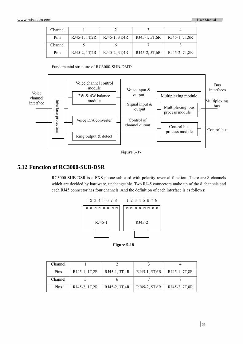
www.raisecom.com User Manual
33
Channel 1 2 3 4
Pins RJ45-1, 1T,2R RJ45-1, 3T,4R RJ45-1, 5T,6R RJ45-1, 7T,8R
Channel 5 6 7 8
Pins RJ45-2, 1T,2R RJ45-2, 3T,4R RJ45-2, 5T,6R RJ45-2, 7T,8R
Fundamental structure of RC3000-SUB-DMT:
5.12 Function of RC3000-SUB-DSR
RC3000-SUB-DSR is a FXS phone sub-card with polarity reversal function. There are 8 channels which are decided by hardware, unchangeable. Two RJ45 connectors make up of the 8 channels and each RJ45 connector has four channels. And the definition of each interface is as follows:
Channel 1 2 3 4
Pins RJ45-1, 1T,2R RJ45-1, 3T,4R RJ45-1, 5T,6R RJ45-1, 7T,8R
Channel 5 6 7 8
Pins RJ45-2, 1T,2R RJ45-2, 3T,4R RJ45-2, 5T,6R RJ45-2, 7T,8R
1 2 3 4 5 6 7 8 1 2 3 4 5 6 7 8
Figure 5-18
RJ45-1 RJ45-2
Voice channel control module
Multiplexing module Voice channel interface
Bus interfaces
Multiplexing bus
Control bus
Multiplexing bus process module
Control bus process module
Voice input & output
Signal input & output
Control of channel output
2W & 4W balance module
Voice D/A converter
Ring output & detect
Interface protection
Figure 5-17
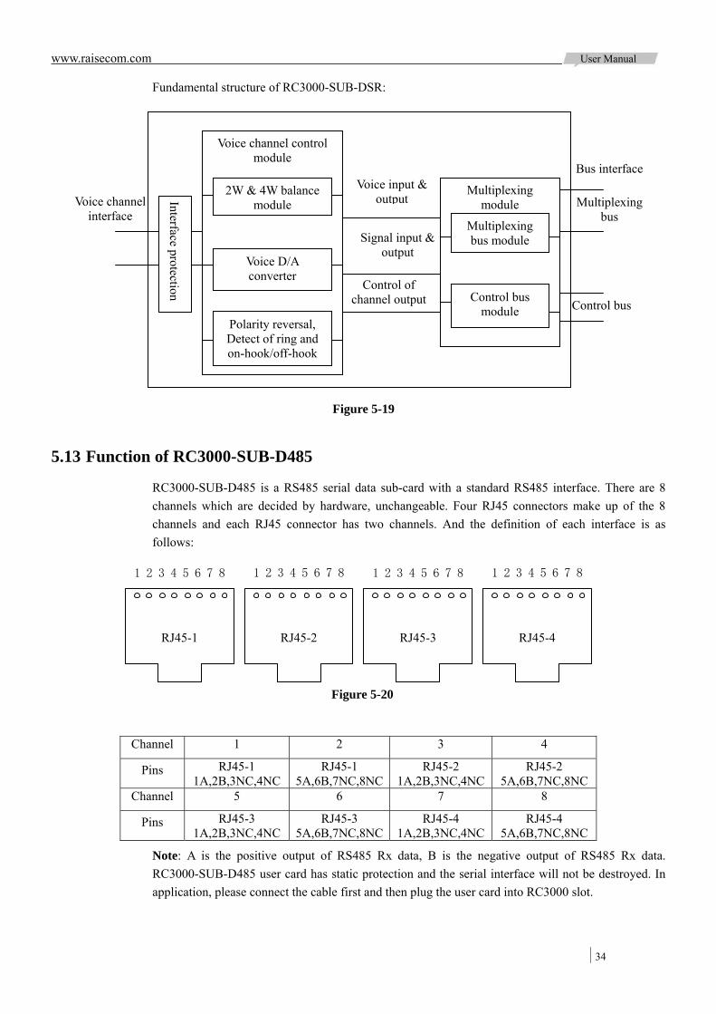
www.raisecom.com User Manual
34
Fundamental structure of RC3000-SUB-DSR:
5.13 Function of RC3000-SUB-D485
RC3000-SUB-D485 is a RS485 serial data sub-card with a standard RS485 interface. There are 8 channels which are decided by hardware, unchangeable. Four RJ45 connectors make up of the 8 channels and each RJ45 connector has two channels. And the definition of each interface is as follows:
Channel 1 2 3 4
Pins RJ45-1 1A,2B,3NC,4NC
RJ45-1 5A,6B,7NC,8NC
RJ45-2 1A,2B,3NC,4NC
RJ45-2 5A,6B,7NC,8NC
Channel 5 6 7 8
Pins RJ45-3 1A,2B,3NC,4NC
RJ45-3 5A,6B,7NC,8NC
RJ45-4 1A,2B,3NC,4NC
RJ45-4 5A,6B,7NC,8NC
Note: A is the positive output of RS485 Rx data, B is the negative output of RS485 Rx data. RC3000-SUB-D485 user card has static protection and the serial interface will not be destroyed. In application, please connect the cable first and then plug the user card into RC3000 slot.
1 2 3 4 5 6 7 8 1 2 3 4 5 6 7 8
RJ45-1 RJ45-2
1 2 3 4 5 6 7 8 1 2 3 4 5 6 7 8
Figure 5-20
RJ45-3 RJ45-4
Control of channel output
Voice channel control module
Multiplexing module Voice channel
interface
Bus interface
Multiplexing bus
Multiplexing bus module
Control bus module
Voice input & output
Signal input & output
2W & 4W balance module
Voice D/A converter
Polarity reversal, Detect of ring and on-hook/off-hook
Interface protection
Figure 5-19
Control bus
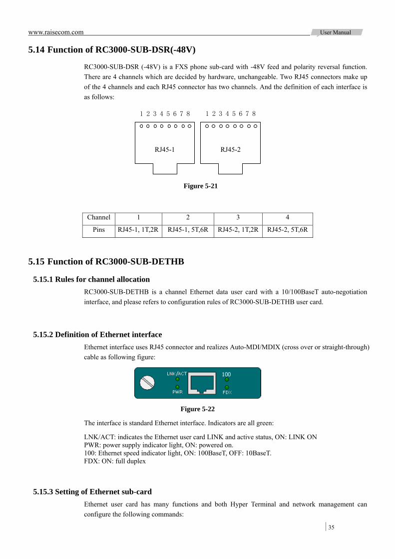
www.raisecom.com User Manual
35
5.14 Function of RC3000-SUB-DSR(-48V)
RC3000-SUB-DSR (-48V) is a FXS phone sub-card with -48V feed and polarity reversal function. There are 4 channels which are decided by hardware, unchangeable. Two RJ45 connectors make up of the 4 channels and each RJ45 connector has two channels. And the definition of each interface is as follows:
Channel 1 2 3 4
Pins RJ45-1, 1T,2R RJ45-1, 5T,6R RJ45-2, 1T,2R RJ45-2, 5T,6R
5.15 Function of RC3000-SUB-DETHB
5.15.1 Rules for channel allocation RC3000-SUB-DETHB is a channel Ethernet data user card with a 10/100BaseT auto-negotiation interface, and please refers to configuration rules of RC3000-SUB-DETHB user card.
5.15.2 Definition of Ethernet interface Ethernet interface uses RJ45 connector and realizes Auto-MDI/MDIX (cross over or straight-through) cable as following figure:
Figure 5-22
The interface is standard Ethernet interface. Indicators are all green:
LNK/ACT: indicates the Ethernet user card LINK and active status, ON: LINK ON PWR: power supply indicator light, ON: powered on. 100: Ethernet speed indicator light, ON: 100BaseT, OFF: 10BaseT. FDX: ON: full duplex
5.15.3 Setting of Ethernet sub-card Ethernet user card has many functions and both Hyper Terminal and network management can configure the following commands:
1 2 3 4 5 6 7 8 1 2 3 4 5 6 7 8
Figure 5-21
RJ45-1 RJ45-2
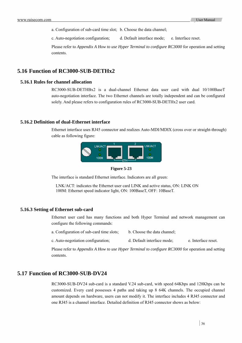
www.raisecom.com User Manual
36
a. Configuration of sub-card time slot; b. Choose the data channel;
c. Auto-negotiation configuration; d. Default interface mode; e. Interface reset.
Please refer to Appendix A How to use Hyper Terminal to configure RC3000 for operation and setting contents.
5.16 Function of RC3000-SUB-DETHx2
5.16.1 Rules for channel allocation RC3000-SUB-DETHBx2 is a dual-channel Ethernet data user card with dual 10/100BaseT auto-negotiation interface. The two Ethernet channels are totally independent and can be configured solely. And please refers to configuration rules of RC3000-SUB-DETHx2 user card.
5.16.2 Definition of dual-Ethernet interface Ethernet interface uses RJ45 connector and realizes Auto-MDI/MDIX (cross over or straight-through) cable as following figure:
Figure 5-23
The interface is standard Ethernet interface. Indicators are all green:
LNK/ACT: indicates the Ethernet user card LINK and active status, ON: LINK ON 100M: Ethernet speed indicator light, ON: 100BaseT, OFF: 10BaseT.
5.16.3 Setting of Ethernet sub-card Ethernet user card has many functions and both Hyper Terminal and network management can configure the following commands:
a. Configuration of sub-card time slots; b. Choose the data channel;
c. Auto-negotiation configuration; d. Default interface mode; e. Interface reset.
Please refer to Appendix A How to use Hyper Terminal to configure RC3000 for operation and setting contents.
5.17 Function of RC3000-SUB-DV24
RC3000-SUB-DV24 sub-card is a standard V.24 sub-card, with speed 64Kbps and 128Kbps can be customized. Every card possesses 4 paths and taking up 8 64K channels. The occupied channel amount depends on hardware, users can not modify it. The interface includes 4 RJ45 connector and one RJ45 is a channel interface. Detailed definition of RJ45 connector shows as below:
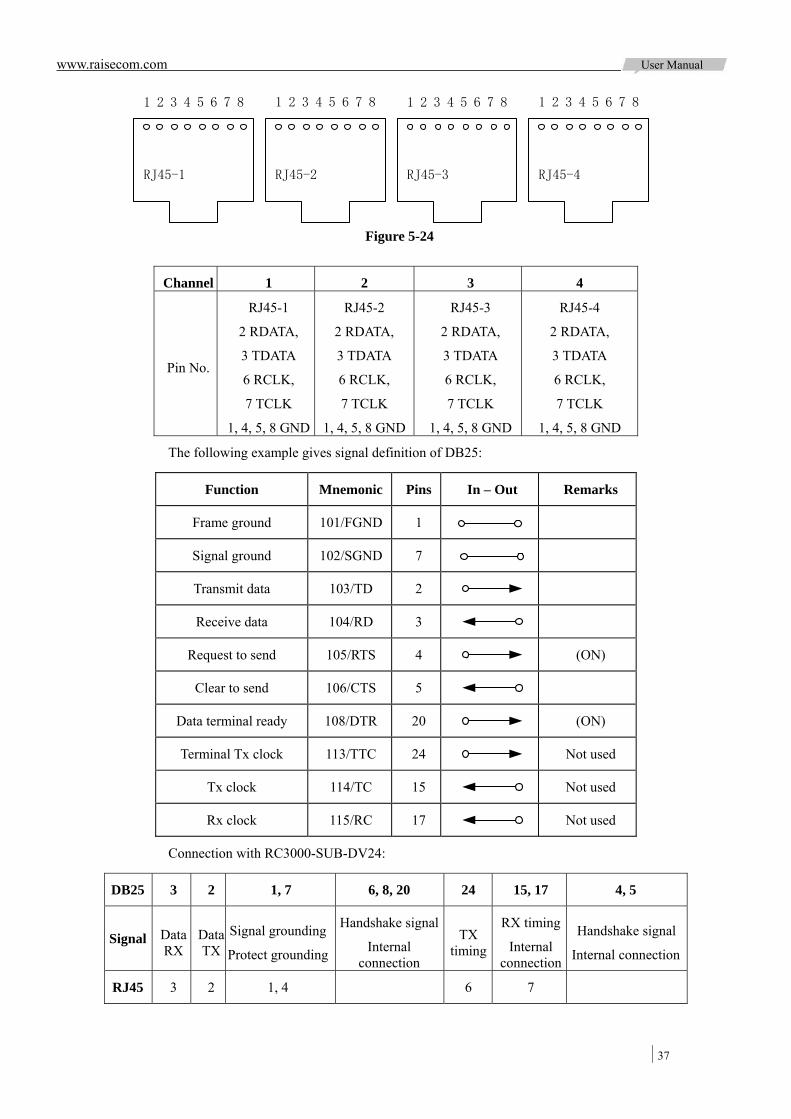
www.raisecom.com User Manual
37
Channel 1 2 3 4
Pin No.
RJ45-1
2 RDATA,
3 TDATA
6 RCLK,
7 TCLK
1, 4, 5, 8 GND
RJ45-2
2 RDATA,
3 TDATA
6 RCLK,
7 TCLK
1, 4, 5, 8 GND
RJ45-3
2 RDATA,
3 TDATA
6 RCLK,
7 TCLK
1, 4, 5, 8 GND
RJ45-4
2 RDATA,
3 TDATA
6 RCLK,
7 TCLK
1, 4, 5, 8 GND
The following example gives signal definition of DB25:
Function Mnemonic Pins In – Out Remarks
Frame ground 101/FGND 1
Signal ground 102/SGND 7
Transmit data 103/TD 2
Receive data 104/RD 3
Request to send 105/RTS 4 (ON)
Clear to send 106/CTS 5
Data terminal ready 108/DTR 20 (ON)
Terminal Tx clock 113/TTC 24 Not used
Tx clock 114/TC 15 Not used
Rx clock 115/RC 17 Not used
Connection with RC3000-SUB-DV24:
DB25 3 2 1, 7 6, 8, 20 24 15, 17 4, 5
Signal Data RX
Data TX
Signal grounding
Protect grounding
Handshake signal
Internal connection
TX timing
RX timing
Internal connection
Handshake signal
Internal connection
RJ45 3 2 1, 4 6 7
1 2 3 4 5 6 7 8 1 2 3 4 5 6 7 8
RJ45-1 RJ45-2
1 2 3 4 5 6 7 8 1 2 3 4 5 6 7 8
Figure 5-24
RJ45-3 RJ45-4

www.raisecom.com User Manual
38
5.17.1 Timeslot setting rules RC3000-SUB-DV24 is a sub-card with fixed timeslot bandwidth, it is fixed to take up 8 timeslots, every path can set relevant channels according to bandwidth. Corresponding relationship as below table shows:
Path 1 2 3 4
Bandwidth 64k (occupy channel) 1 3 5 7
Bandwidth 128k (occupy channel) 1, 2 3, 4 5, 6 7, 8
5.18 Function of RC3000-SUB-DC64K
RC3000-SUB-DC64K is 4 line 64K date card, the interface symbol rate is 265KBps .each card has 4 channels, and occupies 4 line 64K channels (each channel occupies 1 line 64K channel), and the number of channels occupied is determined by hardware without change. Interface is made up of 2 RJ45; each RJ45 provides 2 user interfaces.
5.18.1 Panel diagram
Figure 40
5.18.2 Indicator description LOS: ON: signal loss alarm; OFF: no warning; When the channel use the internal error tester to test, the indicator will express LOS alarm in tested lines, ON: alarm; OFF: no warning. AIS: ON: the signal is the whole "1" warning, OFF: no warning. When the channel use the internal error tester to test, the indicator will indicator that the test results, ON: error, OFF: no error.
5.18.3 Interface diagram
RJ45 connector RJ45 socket
Figure 41
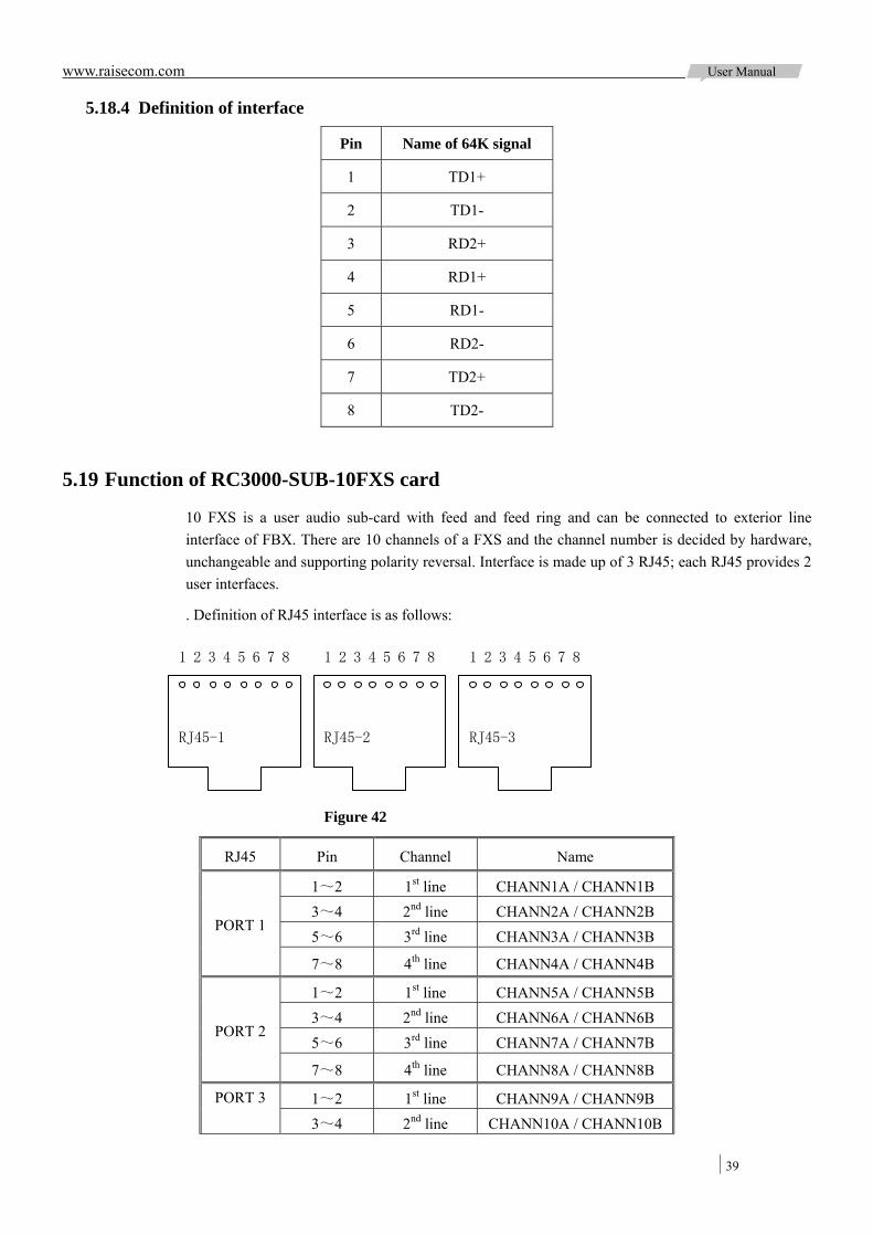
www.raisecom.com User Manual
39
5.18.4 Definition of interface
Pin Name of 64K signal
1 TD1+
2 TD1-
3 RD2+
4 RD1+
5 RD1-
6 RD2-
7 TD2+
8 TD2-
5.19 Function of RC3000-SUB-10FXS card
10 FXS is a user audio sub-card with feed and feed ring and can be connected to exterior line interface of FBX. There are 10 channels of a FXS and the channel number is decided by hardware, unchangeable and supporting polarity reversal. Interface is made up of 3 RJ45; each RJ45 provides 2 user interfaces.
. Definition of RJ45 interface is as follows:
RJ45 Pin Channel Name
1~2 1st line CHANN1A / CHANN1B 3~4 2nd line CHANN2A / CHANN2B 5~6 3rd line CHANN3A / CHANN3B
PORT 1
7~8 4th line CHANN4A / CHANN4B
1~2 1st line CHANN5A / CHANN5B 3~4 2nd line CHANN6A / CHANN6B 5~6 3rd line CHANN7A / CHANN7B
PORT 2
7~8 4th line CHANN8A / CHANN8B
1~2 1st line CHANN9A / CHANN9B PORT 3
3~4 2nd line CHANN10A / CHANN10B
1 2 3 4 5 6 7 8 1 2 3 4 5 6 7 8
Figure 42
RJ45-1 RJ45-2
1 2 3 4 5 6 7 8
RJ45-3

www.raisecom.com User Manual
40
5~6 Reserved
7~8 Reserved
Principle of RC3000-SUB-10FXS is as follow:
5.20 Function of RC3000-SUB-10FXO card
10 FXO audio sub-card is a relay interface module relaying FBX voice channel. There are 10 channels of a FXO and the channel number is decided by hardware and unchangeable. Interface is made up of 3 RJ45; Definition of RJ45 interface is as follows:
RJ45 Pin Channel Name
1~2 1st line CHANN1A / CHANN1B 3~4 2nd line CHANN2A / CHANN2B
PORT 1
5~6 3rd line CHANN3A / CHANN3B
Multiplexing bus module
Figure 43
Voice channelinterface
Voice channel control module Multiplexing
module
Control bus module
Voice input & output
Control of channel output
Interface protection
Signal input & output
2W & 4W balance module
Voice D/A converter
Detect of ring and on-hook/off-hook
Bus interface
Multiplexing bus
Control bus
1 2 3 4 5 6 7 8 1 2 3 4 5 6 7 8
Figure 44
RJ45-1 RJ45-2
1 2 3 4 5 6 7 8
RJ45-3
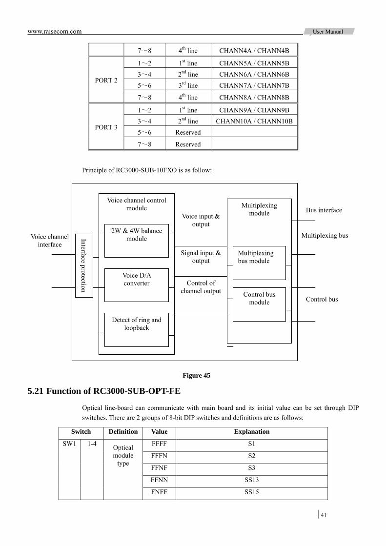
www.raisecom.com User Manual
41
7~8 4th line CHANN4A / CHANN4B
1~2 1st line CHANN5A / CHANN5B 3~4 2nd line CHANN6A / CHANN6B 5~6 3rd line CHANN7A / CHANN7B
PORT 2
7~8 4th line CHANN8A / CHANN8B
1~2 1st line CHANN9A / CHANN9B 3~4 2nd line CHANN10A / CHANN10B 5~6 Reserved
PORT 3
7~8 Reserved
Principle of RC3000-SUB-10FXO is as follow:
5.21 Function of RC3000-SUB-OPT-FE
Optical line-board can communicate with main board and its initial value can be set through DIP switches. There are 2 groups of 8-bit DIP switches and definitions are as follows:
Switch Definition Value Explanation
FFFF S1
FFFN S2
FFNF S3
FFNN SS13
SW1 1-4 Optical module
type
FNFF SS15
Multiplexing bus module
Figure 45
Voice channelinterface
Voice channel control module Multiplexing
module
Control bus module
Voice input & output
Control of channel output
Interface protection
Signal input & output
2W & 4W balance module
Voice D/A converter
Detect of ring and loopback
Bus interface
Multiplexing bus
Control bus
www.raisecom.com User Manual
42
FNFN SS23
FNNF SS25
FNNN S1FC
NFFF M
Other Reporting S1 (0000) trap if set bits in Other status
F Without ALS function 5 ALS
N With ALS function
F Enable auto negotiation function 6 Auto
negotiation N Disable auto negotiation function
F Ethernet port rate is 100M (auto negotiation disable)7 100M/10M
N Ethernet port rate is 10M (auto negotiation disable)
F Ethernet port works in full duplex mode (auto negotiation disable) 8 Full/half
duplex N Ethernet port works in half duplex mode (auto negotiation disable)
F Relative E1 line works normally 1-4 1-4E1
Loop back N Relative E1 line is doing the loop back test
F Local loop back 5 Loop back
type N Remote loop back
SW2
6-8 Reserved Reserved
Note: F stands for OFF and N stands for ON status. Network management has higher privilege than DIP switches except optical module type and ALS function configuration. All configuration information is available through Hyper Terminal. Bit 1-5 of SW1 are set by default in factory according to optical module type and other bits are all OFF.
5.22 Function of RC3000-SUB-OPT-2E1
Optical line-board can communicate with main board and its initial value can be set through DIP switches. There are 3 groups of 8-bit DIP switches and definitions are as follows:
Switch Definition Value Explanation
FFFF S1
FFFN S2
FFNF S3
FFNN SS13
FNFF SS15
FNFN SS23
FNNF SS25
FNNN S1FC
NFFF M
SW1
1-4 Optical module
type
Other Reporting S1 (0000) trap if set bits in Other status
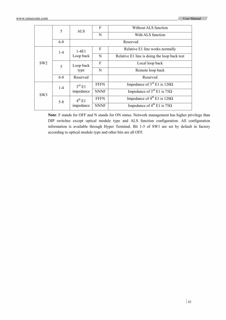
www.raisecom.com User Manual
43
F Without ALS function 5 ALS
N With ALS function
6-8 Reserved
F Relative E1 line works normally 1-4 1-4E1
Loop back N Relative E1 line is doing the loop back test
F Local loop back 5 Loop back
type N Remote loop back
SW2
6-8 Reserved Reserved
FFFN Impedance of 3rd E1 is 120Ω 1-4 3rd E1
impedance NNNF Impedance of 3rd E1 is 75Ω
FFFN Impedance of 4th E1 is 120Ω SW3
5-8 4th E1 impedance NNNF Impedance of 4th E1 is 75Ω
Note: F stands for OFF and N stands for ON status. Network management has higher privilege than DIP switches except optical module type and ALS function configuration. All configuration information is available through Hyper Terminal. Bit 1-5 of SW1 are set by default in factory according to optical module type and other bits are all OFF.
www.raisecom.com User Manual
44
Chapter 6 Installation and Testing
6.1 Unpacking check-up
Check whether the type of device, spare parts and number are same with that of packing list. Make sure the device appearance is in excellent condition. There must be drying process if the device has been damp.
6.2 Preparation before installation
a. Read this manual carefully
b. Verify all the cables are good for normal use. (Please refer to relative chapter for the connection method of cables).
c. Make sure that the voltage of power supply is within the range and grounding protection.
d. Preparing the bit error rate test and optical power meter for necessary line tests.
e. For the devices to be installed, please consider their positions and the length of cables. We recommend you have a whole topology first.
6.3 Installing process
6.3.1 Fix the device RC3000 can be installed in the chassis or on rack. Please make sure that the installation is firm and convenience for operation.
6.3.2 Connecting cables a. Connect the power supply and ground:
There are both AC power supply and DC power supply of RC3000, no matter which kind of power supply make sure of good grounding protection. And the chassis grounding of RC3000 must be connected to that of other device and the earth. Otherwise the device may not work normally.
b. E1 signal interface:
The E1 interfaces of RC3000-2E1 are CC3 interfaces, and the E1 interfaces of RC3000-4E1 are RJ45 balanced E1 interfaces. Please use the attached cables we offered, and when you need to transfer balanced interfaces to unbalanced ones RC909-4E1 of Raisecom is available.
c. Optical interface:
SC connector is for optical interface. And if you are not sure of Rx & Tx direction, please connect the connector before device powered on.
d. Connect network management interface:

www.raisecom.com User Manual
45
When this device is connected with network management PC, connect cable to LINK UP interface; and when you need network management concatenation, connect cable to LINK DOWN interface. Please connect to network management interface before device powered on if you are not sure of common grounding.
6.3.3 Power on and setting the device a. Verify all the connections are normal (power supply and interfaces), and than powered on.
b. Verify the self-check of the device is normal (PWR is ON and SYS is flickering). Buzzer will buzz if there are alarms and MUTE button can shutdown present alarm sound.
c. You do not need to configure the device for point-to-point topology. Use CONSOLE interface to configure the device when necessary.
d. RC3000 will work normally if all connections are right.

www.raisecom.com User Manual
46
Chapter 7 FAQ
7.1 SYS is ON
When there are alarms SYS will be ON. You can check the alarm information through network management or Hyper Terminal to confirm why the buzzer buzzes:
a. Fail to communicate with user card. b. Fail to communicate with line-board when line-board is RC3000-OPT. c. Collision of channel occupation. d. Fan problems. e. Temperature collection problems.
If these are not the reasons why buzzer buzzes, please contact us for technical support.
7.2 Alarms of E1 interface
If there are LOF, LOS or AIS alarms, please check the followings:
a. Cable of E1 or optical interface has been correctly connected. b. Device connected to RC3000 works normally. c. If E1 is not used, please shut it down. d. Verify the impedance of both ends match each other, or change the impedance. e. Verify grounding protection.
If these are not the reasons, please contact us for technical support.
7.3 Cross connection cannot communicate normally
If channels cannot communicate normally, judge from the followings:
a. RC3000s of both ends work normally, otherwise reset the devices. b. Correct use of user cards in both ends. c. Verify the cables connected to user cards are good. d. Verify the synchronization of devices at both ends. e. Correct cross connection. f. Verify correct parameter configuration, such as signal mode, data phase and etc.
If these are not the reasons, please contact us for technical support.
7.4 There is no alarm but voice channel is discontinuous or communication is abnormal
Generally asynchronous of multi-frame causes this phenomenon, check whether there is loss of multi-frame of RC3000 E1 interface or CRC loss of multi-frame. If there is loss of multi-frame, the followings can resolve this problem:
a. Enable or Mask CRC4 to synchronize the two ends. b. Make sure of synchronous clock, and we recommend one clock in one network. c. User cards work normally.
www.raisecom.com User Manual
47
If these are not the reasons, please contact us for technical support.
7.5 There is LOF or RAL alarms sometimes of E1 interface
Generally it is caused by clock asynchronous. In practice application, all RC3000s in one network will synchronous with one clock (that is to say one master clock and several slave clocks), when all devices synchronous with a nonexistent clock or trace clock each other, this phenomenon will happen. Please check the clock configuration.
If these are not the reasons, please contact us for technical support.
7.6 Not all devices in a network can be network managed
If not all devices in a network can be managed, please check the followings:
a. Check the cables connected to all devices first. b. Check the network topology. c. Check the DIP-switches of device that cannot be managed, remember to set first bit
(CONSOLE control bit) OFF. d. Check the network management configuration, make sure that time slot for network
management of all devices is the same (occupy time slot 0 or 1) and number of network management channels is same with that of E1 direction.
e. When manage two RC3000-OPT devices, the network management topology should be single E1 direction, otherwise you may not manage the remote device
f. Check the configuration of device ID and Baud rate, in a RC3000 network all devices must have different ID and same baud rate, and when assistant network management channel is used, the Baud rate must be 2400Bps.
If these are not the reasons why you cannot manage the device, please contact us for technical support.
7.7 Device cannot be configured through CONSOLE
If the device cannot be configured through CONSOLE, please check the followings:
a. Check that proper cable is used to connect to CONSOLE. b. Check the configuration of Hyper Terminal (refer to appendix A: How to use Hyper Terminal) c. Check the DIP-switches and see if the Console control bit ON. d. In Hyper Terminal press <M> to display the menu if <ENTER> key is not effective. e. When you press the <ENTER>, light of serial interface Tx will lighten and this indicates that
RC3000 receives data normally. Otherwise check other configuration. f. Check serial interface
If these are not the reasons why you cannot configure the device, please contact us for technical support.
7.8 Memory information loss
If the information saved in memory lost after RC3000 running for some time, check whether EEPROM can save data normally, if not, please contact us for technical support.

www.raisecom.com User Manual
48
7.9 Display of device is abnormal
When RC3000 cannot display alarms correctly, check the followings:
a. Device voltage ripple is too high and voltage of MCU is not stable, so there is error of program data. In this status please try to cut off electricity and then power on the device again.
b. Equipments inside the device is destroyed.
7.10 Forget the password
When forget your password, you should bring the device back to Raisecom to renew password.
7.11 User port alarm indication of self-loop DC64K sub-card is inconsistent for different uplink cards
a. When uplink card is E1 interface, self-loop user port of RC3000-SUB-DC64K sub-card, then LOS and AIS indicators are in OFF state.
b. When uplink card is optical interface, self-loop user port of RC3000-SUB-DC64K sub-card, then LOS indicator is in OFF state while AIS in ON state.
The above-mentioned phenomena associated with uplink card type, in such circumstances, RC3000-SUB-DC64K is trouble-free. When test self-loop, firstly self-loop E1 port, and then self-loop RC3000-SUB-DC64K sub-card port; when the LOS is in OFF state on RC3000-SUB-DC64K sub-card; AIS displays in ON state.
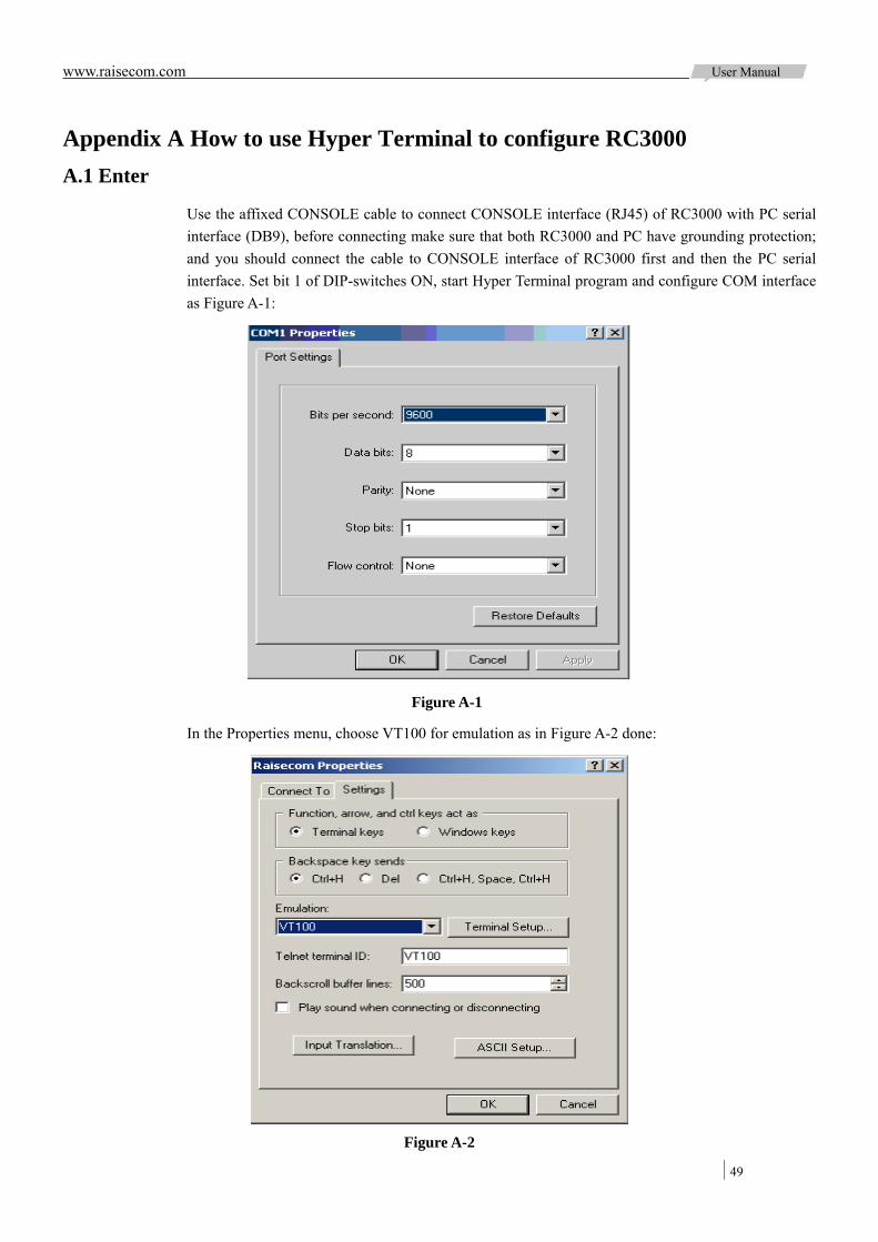
www.raisecom.com User Manual
49
Appendix A How to use Hyper Terminal to configure RC3000 A.1 Enter
Use the affixed CONSOLE cable to connect CONSOLE interface (RJ45) of RC3000 with PC serial interface (DB9), before connecting make sure that both RC3000 and PC have grounding protection; and you should connect the cable to CONSOLE interface of RC3000 first and then the PC serial interface. Set bit 1 of DIP-switches ON, start Hyper Terminal program and configure COM interface as Figure A-1:
Figure A-1
In the Properties menu, choose VT100 for emulation as in Figure A-2 done:
Figure A-2
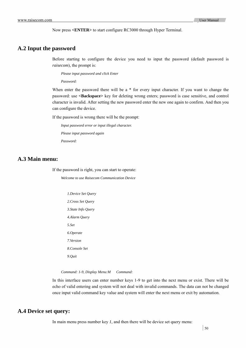
www.raisecom.com User Manual
50
Now press <ENTER> to start configure RC3000 through Hyper Terminal.
A.2 Input the password
Before starting to configure the device you need to input the password (default password is raisecom), the prompt is:
Please input password and click Enter
Password:
When enter the password there will be a * for every input character. If you want to change the password: use <Backspace> key for deleting wrong enters; password is case sensitive, and control character is invalid. After setting the new password enter the new one again to confirm. And then you can configure the device.
If the password is wrong there will be the prompt:
Input password error or input illegal character.
Please input password again
Password:
A.3 Main menu:
If the password is right, you can start to operate:
Welcome to use Raisecom Communication Device
1.Device Set Query
2.Cross Set Query
3.State Info Query
4.Alarm Query
5.Set
6.Operate
7.Version
8.Console Set
9.Quit
Command: 1-9, Display Menu:M Command:
In this interface users can enter number keys 1-9 to get into the next menu or exist. There will be echo of valid entering and system will not deal with invalid commands. The data can not be changed once input valid command key value and system will enter the next menu or exit by automation.
A.4 Device set query:
In main menu press number key 1, and then there will be device set query menu:
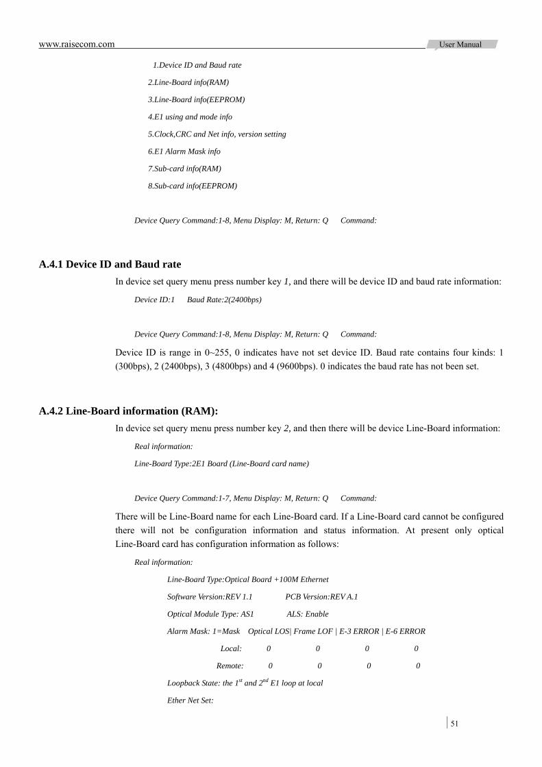
www.raisecom.com User Manual
51
1.Device ID and Baud rate
2.Line-Board info(RAM)
3.Line-Board info(EEPROM)
4.E1 using and mode info
5.Clock,CRC and Net info, version setting
6.E1 Alarm Mask info
7.Sub-card info(RAM)
8.Sub-card info(EEPROM)
Device Query Command:1-8, Menu Display: M, Return: Q Command:
A.4.1 Device ID and Baud rate In device set query menu press number key 1, and there will be device ID and baud rate information:
Device ID:1 Baud Rate:2(2400bps)
Device Query Command:1-8, Menu Display: M, Return: Q Command:
Device ID is range in 0~255, 0 indicates have not set device ID. Baud rate contains four kinds: 1 (300bps), 2 (2400bps), 3 (4800bps) and 4 (9600bps). 0 indicates the baud rate has not been set.
A.4.2 Line-Board information (RAM): In device set query menu press number key 2, and then there will be device Line-Board information:
Real information:
Line-Board Type:2E1 Board (Line-Board card name)
Device Query Command:1-7, Menu Display: M, Return: Q Command:
There will be Line-Board name for each Line-Board card. If a Line-Board card cannot be configured there will not be configuration information and status information. At present only optical Line-Board card has configuration information as follows:
Real information:
Line-Board Type:Optical Board +100M Ethernet
Software Version:REV 1.1 PCB Version:REV A.1
Optical Module Type: AS1 ALS: Enable
Alarm Mask: 1=Mask Optical LOS| Frame LOF | E-3 ERROR | E-6 ERROR
Local: 0 0 0 0
Remote: 0 0 0 0
Loopback State: the 1st and 2nd E1 loop at local
Ether Net Set:
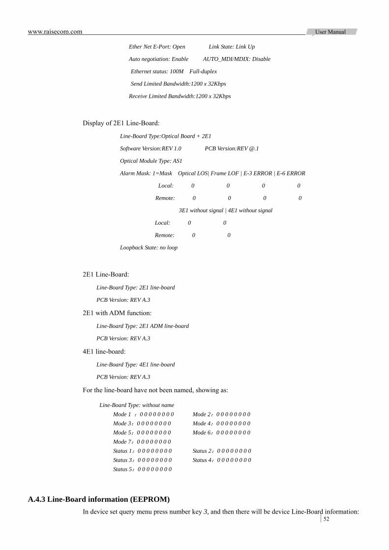
www.raisecom.com User Manual
52
Ether Net E-Port: Open Link State: Link Up
Auto negotiation: Enable AUTO_MDI/MDIX: Disable
Ethernet status: 100M Full-duplex
Send Limited Bandwidth:1200 x 32Kbps
Receive Limited Bandwidth:1200 x 32Kbps
Display of 2E1 Line-Board:
Line-Board Type:Optical Board + 2E1
Software Version:REV 1.0 PCB Version:REV @.1
Optical Module Type: AS1
Alarm Mask: 1=Mask Optical LOS| Frame LOF | E-3 ERROR | E-6 ERROR
Local: 0 0 0 0
Remote: 0 0 0 0
3E1 without signal | 4E1 without signal
Local: 0 0
Remote: 0 0
Loopback State: no loop
2E1 Line-Board:
Line-Board Type: 2E1 line-board
PCB Version: REV A.3
2E1 with ADM function:
Line-Board Type: 2E1 ADM line-board
PCB Version: REV A.3
4E1 line-board:
Line-Board Type: 4E1 line-board
PCB Version: REV A.3
For the line-board have not been named, showing as:
Line-Board Type: without name Mode 1 :0 0 0 0 0 0 0 0 Mode 2:0 0 0 0 0 0 0 0 Mode 3:0 0 0 0 0 0 0 0 Mode 4:0 0 0 0 0 0 0 0 Mode 5:0 0 0 0 0 0 0 0 Mode 6:0 0 0 0 0 0 0 0 Mode 7:0 0 0 0 0 0 0 0 Status 1:0 0 0 0 0 0 0 0 Status 2:0 0 0 0 0 0 0 0 Status 3:0 0 0 0 0 0 0 0 Status 4:0 0 0 0 0 0 0 0 Status 5:0 0 0 0 0 0 0 0
A.4.3 Line-Board information (EEPROM) In device set query menu press number key 3, and then there will be device Line-Board information:
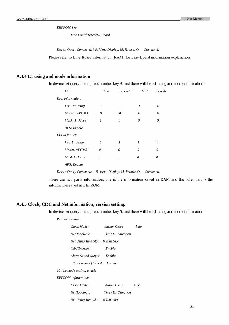
www.raisecom.com User Manual
53
EEPROM Set:
Line-Board Type:2E1 Board
Device Query Command:1-8, Menu Display: M, Return: Q Command:
Please refer to Line-Board information (RAM) for Line-Board information explanation.
A.4.4 E1 using and mode information In device set query menu press number key 4, and there will be E1 using and mode information:
E1: First Second Third Fourth
Real information:
Use: 1=Using 1 1 1 0
Mode: 1=PCM31 0 0 0 0
Mask: 1=Mask 1 1 0 0
APS: Enable
EEPROM Set:
Use:1=Using 1 1 1 0
Mode:1=PCM31 0 0 0 0
Mask:1=Mask 1 1 0 0
APS: Enable
Device Query Command: 1-8, Menu Display: M, Return: Q Command:
There are two parts information, one is the information saved in RAM and the other part is the information saved in EEPROM.
A.4.5 Clock, CRC and Net information, version setting: In device set query menu press number key 5, and there will be E1 using and mode information:
Real information:
Clock Mode: Master Clock Auto
Net Topology: Three E1 Direction
Net Using Time Slot: 0 Time Slot
CRC Transmit: Enable
Alarm Sound Output: Enable
Work mode of VER A: Enable
10-line mode setting: enable
EEPROM information:
Clock Mode: Master Clock Auto
Net Topology: Three E1 Direction
Net Using Time Slot: 0 Time Slot

www.raisecom.com User Manual
54
CRC Transmit: Enable
Alarm Sound Output: Enable
Work mode of VER A: Enable
10-line mode setting; enable
Device Query Command:1-8, Menu Display: M, Return: Q Command:
Note: Time Slot 1 is not available in network management channels.
Clock modes: Master clock
Slave clock (1 E1)
Slave clock (2 E1)
Slave clock (3 E1)
Slave clock (4 E1)
There are two ways to adapt clock: Auto
Manual
Net topology: Single E1 Direction
Double E1 Direction
Three E1 Direction
Four E1 Direction
Net Using Time Slot: Time Slot 0
Time Slot 1
CRC transmit: enable
disable
Version A work mode: enable
disable
10-line mode setting: enable
disable
Note: there is no timeslot 1 network management channel in fact because of device design.
A.4.6 E1 Alarm Mask information: In device set query menu press number key 6, and there will be E1 Alarm Mask information:
Alarm LOS AIS LOF RAL LOMF LOMFC CRC
Real information:
1st E1 1=Mask 0 0 0 0 0 0 0
2nd E1 1=Mask 0 0 0 0 0 0 0
3rd E1 1=Mask 0 0 0 0 0 0 0
4th E1 1=Mask 0 0 0 0 0 0 0

www.raisecom.com User Manual
55
EEPROM Set:
1st E1 1=Mask 0 0 0 0 0 0 0
2nd E1 1=Mask 0 0 0 0 0 0 0
3rd E1 1=Mask 0 0 0 0 0 0 0
4th E1 1=Mask 0 0 0 0 0 0 0
Device Query Command:1-8, Menu Display: M, Return: Q Command:
There are two parts information, one is the information saved in RAM and the other part is the information saved in EEPROM.
A.4.7 Sub-card information (RAM) In device set query menu press number key 7, there will be the prompt of user board number:
Input User Board No.(1-3, Esc=Cancel):
Then chose the sub-card number you want to query and there will be the sub-card information:
Sub-card X:
Type: user-card name timeslot Number: X Set Mode: Hardware
PCB version: REV A.3 CPLD version: REV 1.0
(Set: real setting content)
Device Query Command:1-8, Menu Display: M, Return: Q Command:
Note: System will display there is no definition for the card if input a user card number that is not existed; the information is different according to user card type. State information of different types of card is as below:
Card type 1 FXS audio user sub-card:
Type: 1 FXS sub-card timeslot numbers: 8 Set Mode: Hardware
PCB version: REV A.3 CPLD version: REV 1.0
Signal: Have Input signal: Original signal Output signal: Reversal signal
Signal bit: (CH1:CH2): A A A A B B B B
Card type 2 FXO audio relay sub-card:
Type: 2 FXO sub-card timeslot numbers: 8 Set Mode: Hardware
PCB version: REV A.3 CPLD version: REV 1.0
Signal: Have Input signal: Original signal Output signal: Reversal signal
Signal bit: (CH1:CH2): A A A A B B B B
Card type 3 FXO and FXS hybrid sub-card:
Type: 3 FXS and FXO hybrid sub-card timeslot l numbers: 8 Set Mode: Hardware
PCB version: REV A.3 CPLD version: REV 1.0
Signal: Have Input signal: Original signal Output signal: Reversal signal
Signal bit:(CH1:CH2) : A A A A B B B B
Channel type:(CH1:CH2) : S S S S 0 0 0 0
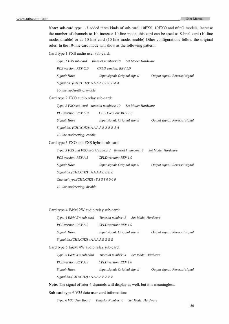
www.raisecom.com User Manual
56
Note: sub-card type 1-3 added three kinds of sub-card: 10FXS, 10FXO and nSnO models, increase the number of channels to 10, increase 10-line mode, this card can be used as 8-linel card (10-line mode: disable) or as 10-line card (10-line mode: enable) Other configurations follow the original rules. In the 10-line card mode will show as the following pattern:
Card type 1 FXS audio user sub-card:
Type: 1 FXS sub-card timeslot numbers:10 Set Mode: Hardware
PCB version: REV C.0 CPLD version: REV 1.0
Signal: Have Input signal: Original signal Output signal: Reversal signal
Signal bit: (CH1:CH2): A A A A B B B B A A
10-line modesetting: enable
Card type 2 FXO audio relay sub-card:
Type: 2 FXO sub-card timeslot numbers: 10 Set Mode: Hardware
PCB version: REV C.0 CPLD version: REV 1.0
Signal: Have Input signal: Original signal Output signal: Reversal signal
Signal bit: (CH1:CH2): A A A A B B B B A A
10-line modesetting: enable
Card type 3 FXO and FXS hybrid sub-card:
Type: 3 FXS and FXO hybrid sub-card timeslot l numbers: 8 Set Mode: Hardware
PCB version: REV A.3 CPLD version: REV 1.0
Signal: Have Input signal: Original signal Output signal: Reversal signal
Signal bit:(CH1:CH2) : A A A A B B B B
Channel type:(CH1:CH2) : S S S S 0 0 0 0
10-line modesetting: disable
Card type 4 E&M 2W audio relay sub-card:
Type: 4 E&M 2W sub-card Timeslot number: 8 Set Mode: Hardware
PCB version: REV A.3 CPLD version: REV 1.0
Signal: Have Input signal: Original signal Output signal: Reversal signal
Signal bit:(CH1:CH2) : A A A A B B B B
Card type 5 E&M 4W audio relay sub-card:
Type: 5 E&M 4W sub-card Timeslot number: 4 Set Mode: Hardware
PCB version: REV A.3 CPLD version: REV 1.0
Signal: Have Input signal: Original signal Output signal: Reversal signal
Signal bit:(CH1:CH2) : A A A A B B B B
Note: The signal of later 4 channels will display as well, but it is meaningless.
Sub-card type 6 V35 data user card information:
Type: 6 V35 User Board Timeslot Number: 0 Set Mode: Hardware
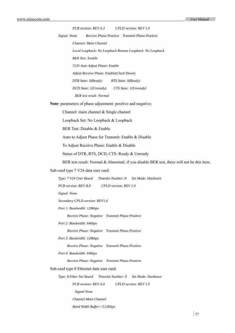
www.raisecom.com User Manual
57
PCB version: REV A.3 CPLD version: REV 1.0
Signal: None Receive Phase:Positive Transmit Phase:Positive
Channel: Main Channel
Local Loopback: No Loopback Remote Loopback: No Loopback
BER Test: Enable
7235 Auto Adjust Phase: Enable
Adjust Receive Phase: Enable(Clock Down)
DTR State: 0(Ready) RTS State: 0(Ready)
DCD State: 1(Unready) CTS State: 1(Unready)
BER test result: Normal
Note: parameters of phase adjustment: positive and negative;
Channel: main channel & Single channel
Loopback Set: No Loopback & Loopback
BER Test: Disable & Enable
Auto to Adjust Phase for Transmit: Enable & Disable
To Adjust Receive Phase: Enable & Disable
Status of DTR, RTS, DCD, CTS: Ready & Unready
BER test result: Normal & Abnormal; if you disable BER test, there will not be this item.
Sub-card type 7 V24 data user card:
Type: 7 V24 User Board Timeslot Number: 8 Set Mode: Hardware
PCB version: REV B.0 CPLD version: REV 1.0
Signal: None
Secondary CPLD version: REV1.0
Port 1: Bandwidth: 128kbps
Receive Phase: Negative Transmit Phase:Positive
Port 2: Bandwidth: 64kbps
Receive Phase: Negative Transmit Phase:Positive
Port 3: Bandwidth: 128kbps
Receive Phase: Negative Transmit Phase:Positive
Port 4: Bandwidth: 64kbps
Receive Phase: Negative Transmit Phase:Positive
Sub-card type 8 Ethernet data user card:
Type: 8 Ether Net Board Timeslot Number: 0 Set Mode: Hardware
PCB version: REV A.0 CPLD version: REV 1.0
Signal:None
Channel:Main Channel
Band Width Buffer:>512Kbps
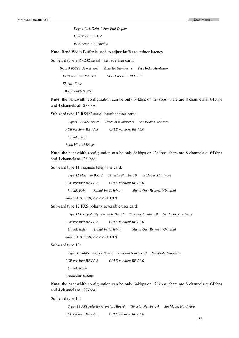
www.raisecom.com User Manual
58
Defeat Link Default Set: Full Duplex
Link State:Link UP
Work State:Full Duplex
Note: Band Width Buffer is used to adjust buffer to reduce latency.
Sub-card type 9 RS232 serial interface user card:
Type: 9 RS232 User Board Timeslot Number: 8 Set Mode: Hardware
PCB version: REV A.3 CPLD version: REV 1.0
Signal: None
Band Width:64Kbps
Note: the bandwidth configuration can be only 64kbps or 128kbps; there are 8 channels at 64kbps and 4 channels at 128kbps.
Sub-card type 10 RS422 serial interface user card:
Type:10 RS422 Board Timeslot Number: 8 Set Mode:Hardware
PCB version: REV A.3 CPLD version: REV 1.0
Signal:Exist
Band Width:64Kbps
Note: the bandwidth configuration can be only 64kbps or 128kbps; there are 8 channels at 64kbps and 4 channels at 128kbps.
Sub-card type 11 magneto telephone card:
Type:11 Magneto Board Timeslot Number: 8 Set Mode:Hardware
PCB version: REV A.3 CPLD version: REV 1.0
Signal: Exist Signal In: Original Signal Out: Reversal Original
Signal Bit(D7:D0):A A A A B B B B
Sub-card type 12 FXS polarity reversible user card:
Type:11 FXS polarity reversible Board Timeslot Number: 8 Set Mode:Hardware
PCB version: REV A.3 CPLD version: REV 1.0
Signal: Exist Signal In: Original Signal Out: Reversal Original
Signal Bit(D7:D0):A A A A B B B B
Sub-card type 13:
Type: 12 R485 interface Board Timeslot Number: 8 Set Mode:Hardware
PCB version: REV A.3 CPLD version: REV 1.0
Signal: None
Bandwidth: 64Kbps
Note: the bandwidth configuration can be only 64kbps or 128kbps; there are 8 channels at 64kbps and 4 channels at 128kbps.
Sub-card type 14:
Type: 14 FXS polarity reversible Board Timeslot Number: 4 Set Mode: Hardware
PCB version: REV A.3 CPLD version: REV 1.0
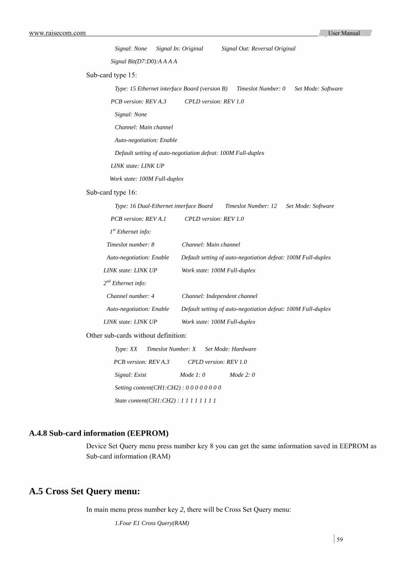
www.raisecom.com User Manual
59
Signal: None Signal In: Original Signal Out: Reversal Original
Signal Bit(D7:D0):A A A A
Sub-card type 15:
Type: 15 Ethernet interface Board (version B) Timeslot Number: 0 Set Mode: Software
PCB version: REV A.3 CPLD version: REV 1.0
Signal: None
Channel: Main channel
Auto-negotiation: Enable
Default setting of auto-negotiation defeat: 100M Full-duplex
LINK state: LINK UP
Work state: 100M Full-duplex
Sub-card type 16:
Type: 16 Dual-Ethernet interface Board Timeslot Number: 12 Set Mode: Software
PCB version: REV A.1 CPLD version: REV 1.0
1st Ethernet info:
Timeslot number: 8 Channel: Main channel
Auto-negotiation: Enable Default setting of auto-negotiation defeat: 100M Full-duplex
LINK state: LINK UP Work state: 100M Full-duplex
2nd Ethernet info:
Channel number: 4 Channel: Independent channel
Auto-negotiation: Enable Default setting of auto-negotiation defeat: 100M Full-duplex
LINK state: LINK UP Work state: 100M Full-duplex
Other sub-cards without definition:
Type: XX Timeslot Number: X Set Mode: Hardware
PCB version: REV A.3 CPLD version: REV 1.0
Signal: Exist Mode 1: 0 Mode 2: 0
Setting content(CH1:CH2) : 0 0 0 0 0 0 0 0
State content(CH1:CH2) : 1 1 1 1 1 1 1 1
A.4.8 Sub-card information (EEPROM) Device Set Query menu press number key 8 you can get the same information saved in EEPROM as Sub-card information (RAM)
A.5 Cross Set Query menu:
In main menu press number key 2, there will be Cross Set Query menu:
1.Four E1 Cross Query(RAM)
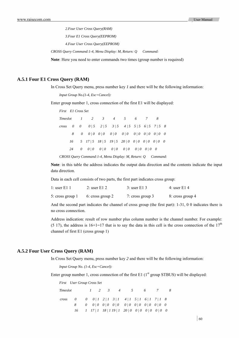
www.raisecom.com User Manual
60
2.Four User Cross Query(RAM)
3.Four E1 Cross Query(EEPROM)
4.Four User Cross Query(EEPROM)
CROSS Query Command:1-4, Menu Display: M, Return: Q Command:
Note: Here you need to enter commands two times (group number is required)
A.5.1 Four E1 Cross Query (RAM) In Cross Set Query menu, press number key 1 and there will be the following information:
Input Group No.(1-4, Esc=Cancel):
Enter group number 1, cross connection of the first E1 will be displayed:
First E1 Cross Set
Timeslot 1 2 3 4 5 6 7 8
cross 0 0 0 | 5 2 | 5 3 | 5 4 | 5 5 | 5 6 | 5 7 | 5 8
8 0 0 | 0 0 | 0 0 | 0 0 | 0 0 | 0 0 | 0 0 | 0 0
16 5 17 | 5 18 | 5 19 | 5 20 | 0 0 | 0 0 | 0 0 | 0 0
24 0 0 | 0 0 | 0 0 | 0 0 | 0 0 | 0 0 | 0 0
CROSS Query Command:1-4, Menu Display: M, Return: Q Command:
Note: in this table the address indicates the output data direction and the contents indicate the input data direction.
Data in each cell consists of two parts, the first part indicates cross group:
1: user E1 1 2: user E1 2 3: user E1 3 4: user E1 4
5: cross group 1 6: cross group 2 7: cross group 3 8: cross group 4
And the second part indicates the channel of cross group (the first part): 1-31, 0 0 indicates there is no cross connection.
Address indication: result of row number plus column number is the channel number. For example: (5 17), the address is 16+1=17 that is to say the data in this cell is the cross connection of the 17th channel of first E1 (cross group 1)
A.5.2 Four User Cross Query (RAM) In Cross Set Query menu, press number key 2 and there will be the following information:
Input Group No. (1-4, Esc=Cancel):
Enter group number 1, cross connection of the first E1 (1st group STBUS) will be displayed:
First User Group Cross Set
Timeslot 1 2 3 4 5 6 7 8
cross 0 0 0 | 1 2 | 1 3 | 1 4 | 1 5 | 1 6 | 1 7 | 1 8 8 0 0 | 0 0 | 0 0 | 0 0 | 0 0 | 0 0 | 0 0 | 0 0 16 1 17 | 1 18 | 1 19 | 1 20 | 0 0 | 0 0 | 0 0 | 0 0
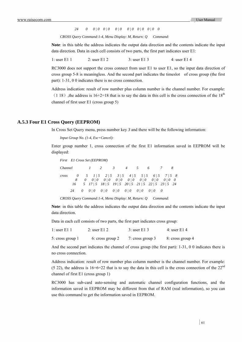
www.raisecom.com User Manual
61
24 0 0 | 0 0 | 0 0 | 0 0 | 0 0 | 0 0 | 0 0
CROSS Query Command:1-4, Menu Display: M, Return: Q Command:
Note: in this table the address indicates the output data direction and the contents indicate the input data direction. Data in each cell consists of two parts, the first part indicates user E1:
1: user E1 1 2: user E1 2 3: user E1 3 4: user E1 4
RC3000 does not support the cross connect from user E1 to user E1, so the input data direction of cross group 5-8 is meaningless. And the second part indicates the timeslot of cross group (the first part): 1-31, 0 0 indicates there is no cross connection.
Address indication: result of row number plus column number is the channel number. For example: (1 18),the address is 16+2=18 that is to say the data in this cell is the cross connection of the 18th channel of first user E1 (cross group 5)
A.5.3 Four E1 Cross Query (EEPROM) In Cross Set Query menu, press number key 3 and there will be the following information:
Input Group No. (1-4, Esc=Cancel):
Enter group number 1, cross connection of the first E1 information saved in EEPROM will be displayed:
First E1 Cross Set (EEPROM)
Channel 1 2 3 4 5 6 7 8
cross 0 5 1 | 5 2 | 5 3 | 5 4 | 5 5 | 5 6 | 5 7 | 5 8 8 0 0 | 0 0 | 0 0 | 0 0 | 0 0 | 0 0 | 0 0 | 0 0
16 5 17 | 5 18 | 5 19 | 5 20 | 5 21 | 5 22 | 5 23 | 5 24
24 0 0 | 0 0 | 0 0 | 0 0 | 0 0 | 0 0 | 0 0
CROSS Query Command:1-4, Menu Display: M, Return: Q Command:
Note: in this table the address indicates the output data direction and the contents indicate the input data direction.
Data in each cell consists of two parts, the first part indicates cross group:
1: user E1 1 2: user E1 2 3: user E1 3 4: user E1 4
5: cross group 1 6: cross group 2 7: cross group 3 8: cross group 4
And the second part indicates the channel of cross group (the first part): 1-31, 0 0 indicates there is no cross connection.
Address indication: result of row number plus column number is the channel number. For example: (5 22), the address is 16+6=22 that is to say the data in this cell is the cross connection of the 22nd channel of first E1 (cross group 1)
RC3000 has sub-card auto-sensing and automatic channel configuration functions, and the information saved in EEPROM may be different from that of RAM (real information), so you can use this command to get the information saved in EEPROM.

www.raisecom.com User Manual
62
A.5.4 Four User Cross Query (EEPROM) In Cross Set Query menu, press number key 4 and there will be the following information:
Input Group No.(1-4, Ese=Cancel):
Enter group number 1, cross connection of the first user E1 information (the 1st STBUS) saved in EEPROM will be displayed:
First User Group Cross Set (EEPROM)
Timeslot 1 2 3 4 5 6 7 8
cross 0 0 0 | 1 2 | 1 3 | 1 4 | 1 5 | 1 6 | 1 7 | 1 8
8 0 0 | 0 0 | 0 0 | 0 0 | 0 0 | 0 0 | 0 0 | 0 0
16 1 17 | 1 18 | 1 19 | 1 20 | 1 21 | 1 22 | 1 23 | 1 24
24 0 0 | 0 0 | 0 0 | 0 0 | 0 0 | 0 0 | 0 0
CROSS Query Command:1-4, Menu Display: M, Return: Q Command:
Note: in this table the address indicates the output data direction and the contents indicate the input data direction. Data in each cell consists of two parts, the first part indicates user E1:
1: user E1 1 2: user E1 2 3: user E1 3 4: user E1 4
RC3000 does not support the cross connect from user group to user group, so the input data direction of cross group 5-7 is meaningless. And the second part indicates the channel of cross group: 1-31. 0 0 indicates there is no cross connection.
Address indication: result of row number plus column number is the channel number. RC3000 has sub-card auto-sensing and automatic channel configuration functions, and the information saved in EEPROM may be different from that of RAM (real information), so you can use this command to get the information saved in EEPROM.
A.6 State Info Query
In main menu press number key 3 there will enter state information query menu:
1.Receive State Query
2.Transmit State Query
State Query Command:1-2, Menu Display: M, Return: Q Command:
A.6.1 Receive State Query In state information query menu press number key 1 there will be the following information:
Input Group No.(1-4, Esc=Cancel):
Enter group number 1, there will receive signal status information:
First Group Receive State
Channel 1 2 3 4 5 6 7 8
state 0 1 | 2 | 3 | 4 | 5 | 6 | 7 | 8
8 9 | 10 | 11 | 12 | 13 | 14 | 15 | 16

www.raisecom.com User Manual
63
16 17 | 18 | 19 | 20 | 21 | 22 | 23 | 24
24 25 | 26 | 27 | 28 | 29 | 30 | 31
State Query Command:1-2, Menu Display: M, Return: Q Command:
Note: the data in each cell is hex and refer to receive signal information of user board, through this command you can get the device work status.
A.6.2 Transmit State Query In state information query menu press number key 2 there will be the following information:
Input Group No.(1-4, Esc=Cancel):
Enter group number 1, there will transmit signal status information:
First Group Transmit State
Channel 1 2 3 4 5 6 7 8
state 0 1 | 2 | 3 | 4 | 5 | 6 | 7 | 8
8 9 | 10 | 11 | 12 | 13 | 14 | 15 | 16
16 17 | 18 | 19 | 20 | 21 | 22 | 23 | 24
24 25 | 26 | 27 | 28 | 29 | 30 | 31
State Query Command:1-2, Menu Display: M, Return: Q Command:
Note: the data in each cell is hex and refer to transmit signal information of user board, through this command you can get the signaling status of user card.
A.7 Alarm Query menu
In main menu press number key 4, there will be alarm query menu:
1.Device Alarm
2.System Alarm
Alarm Query Command:1-2, Menu Display: M, Return: Q Command:
A.7.1 Device Alarm In alarm query menu press number key 1 there will be present device alarm information:
Device Alarm:
1E1 Alarm: LOS, AIS, LOF, RAL, LOMF, CRC LOMF
2E1 Alarm:No Alarm
Local optical interface: No Alarm
Remote optical interface: No Alarm
Alarm Query Command:1-2, Menu Display: M, Return: Q Command:
Note: E1 interface alarms include: LOS, AIS, LOF, RAL, LOMF, CRC and CRC LOMF
Optical interface alarms include: Optical LOS, Frame LOF , E-3 ERROR and E-6 ERROR
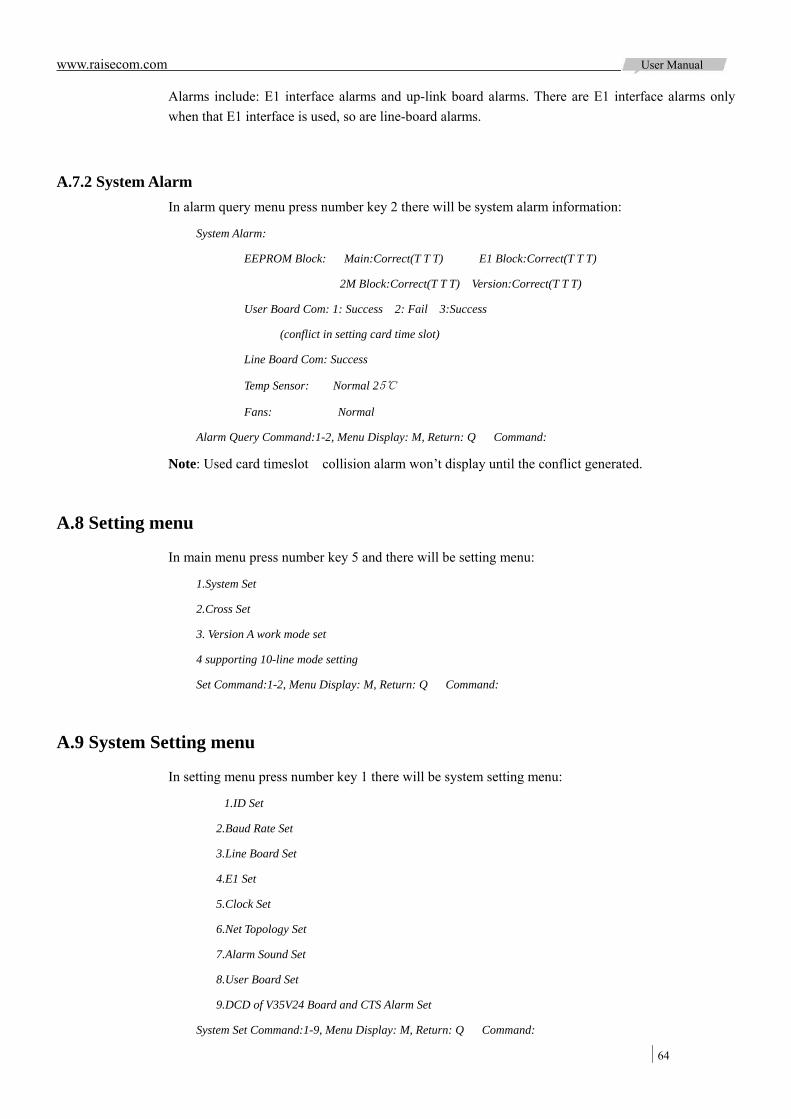
www.raisecom.com User Manual
64
Alarms include: E1 interface alarms and up-link board alarms. There are E1 interface alarms only when that E1 interface is used, so are line-board alarms.
A.7.2 System Alarm In alarm query menu press number key 2 there will be system alarm information:
System Alarm:
EEPROM Block: Main:Correct(T T T) E1 Block:Correct(T T T)
2M Block:Correct(T T T) Version:Correct(T T T)
User Board Com: 1: Success 2: Fail 3:Success
(conflict in setting card time slot)
Line Board Com: Success
Temp Sensor: Normal 25
Fans: Normal
Alarm Query Command:1-2, Menu Display: M, Return: Q Command:
Note: Used card timeslot collision alarm won’t display until the conflict generated.
A.8 Setting menu
In main menu press number key 5 and there will be setting menu:
1.System Set
2.Cross Set
3. Version A work mode set
4 supporting 10-line mode setting
Set Command:1-2, Menu Display: M, Return: Q Command:
A.9 System Setting menu
In setting menu press number key 1 there will be system setting menu:
1.ID Set
2.Baud Rate Set
3.Line Board Set
4.E1 Set
5.Clock Set
6.Net Topology Set
7.Alarm Sound Set
8.User Board Set
9.DCD of V35V24 Board and CTS Alarm Set
System Set Command:1-9, Menu Display: M, Return: Q Command:
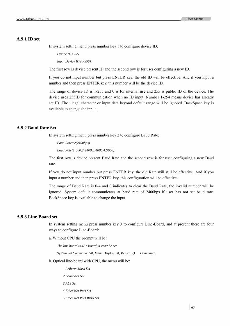
www.raisecom.com User Manual
65
A.9.1 ID set In system setting menu press number key 1 to configure device ID:
Device ID=255
Input Device ID (0-255):
The first row is device present ID and the second row is for user configuring a new ID.
If you do not input number but press ENTER key, the old ID will be effective. And if you input a number and then press ENTER key, this number will be the device ID.
The range of device ID is 1-255 and 0 is for internal use and 255 is public ID of the device. The device uses 255ID for communication when no ID input. Number 1-254 means device has already set ID. The illegal character or input data beyond default range will be ignored. BackSpace key is available to change the input.
A.9.2 Baud Rate Set In system setting menu press number key 2 to configure Baud Rate:
Baud Rate=2(2400bps)
Baud Rate(1:300,2:2400,3:4800,4:9600):
The first row is device present Baud Rate and the second row is for user configuring a new Baud rate.
If you do not input number but press ENTER key, the old Rate will still be effective. And if you input a number and then press ENTER key, this configuration will be effective.
The range of Baud Rate is 0-4 and 0 indicates to clear the Baud Rate, the invalid number will be ignored. System default communicates at baud rate of 2400bps if user has not set baud rate. BackSpace key is available to change the input.
A.9.3 Line-Board set In system setting menu press number key 3 to configure Line-Board, and at present there are four ways to configure Line-Board:
a. Without CPU the prompt will be:
The line board is 4E1 Board, it can't be set.
System Set Command:1-8, Menu Display: M, Return: Q Command:
b. Optical line-board with CPU, the menu will be:
1.Alarm Mask Set
2.Loopback Set
3.ALS Set
4.Ether Net Port Set
5.Ether Net Port Work Set

www.raisecom.com User Manual
66
6.Transmit Band Width Set
7.Receive Band Width Set
8.Reset Ether Net
Optical Board Set Command:1-8, Menu Display: M, Return: Q Command:
Note: the explanation of each command is available in A.10 Line Board Setting menu.
c. 2E1 optical card with CPU, the menu will be:
1.Alarm Mask Set
2.Loopback Set
3.ALS Set
Optical Board (2E1) Set Command:1-3, Menu Display: M, Return: Q Command:
Note: the explanation of each command is available in A.11 2E1 Setting menu.
d. The contents of unknown up-link card have not been registered in system, so relevant configuration information can not be confirmed. In this case, holistic setting solution is available to users, that is users can input binary digit for relevant bytes one by one and the below information will display:
Line-board mode 1 (set value: 0 0 0 0 0 0 0 0 ):
Every byte can be set with different contents according to card type.
If user presses ENTER key direct instead of inputting number, the old setting is effective and system enter mode of the next byte. Once input any content, the command will be effective when pressing ENTER key after inputting all contents.
Pressing ENTER key at the end of byte inputting means confirm the command, and press E key means finish the input and save the former input setting.
Pressing Esc key at any time means cancel the setting.
In case of no content is input, use ↓, ↑keys to shift setting contents and view the setting value. There are 7 bytes of setting contents:
Line-board mode 1
Line-board mode 2
…
Line-board mode 7
A.9.4 E1 set In system setting menu press number key 4 to configure E1 interface and the menu will be:
1.Use Set
2.Mode Set
3.Mask Set
4.CRC Set
E1 Set Command:1-4, Menu Display: M, Return: Q Command:
Note: The explanation of each command is available in A.12 E1 set
www.raisecom.com User Manual
67
A.9.5 E1 Clock Set In system setting menu press number key 5 to configure E1 clock:
Using Clock: Master Clock
In this status, use → key to change the configuration; ENTER and E keys both indicate confirm the operation and press ESC key to cancel.
Clock modes: Master clock
Slave clock (1 E1)
Slave clock (2 E1)
Slave clock (3 E1)
Slave clock (4 E1)
Press ↓ to configure the way to adapt clock:
To Adapt Clock: Auto
There are two ways to adapt clock: Auto & Manual
In Auto Adapt Clock mode RC3000 will set a steady clock mode according to E1 using status and board information.
When there are alarms, system will judge whether to change the clock mode, if necessary RC3000 will find a valid clock to synchronous.
In any status, press ENTER to confirm configuration (or press ENTER until the configuration finished), press E key to finish configuration, and ESC to cancel configuration.
A.9.6 Net channel Set In system setting menu press number key 6 to configure network management channel:
Using Time Slot: 0 Time Slot
In this status, use → key to change the configured value; use ↓↑to change items (using time slot & net topology); Press ENTER to confirm configuration, press E key to finish configuration, and ESC to cancel configuration.
Using time slots are: 0 time slot & 1 time slot
Network management topologies are: Single E1 Direction, Double E1 Direction, Three E1 Direction and Four E1 Direction.
RC3000 has an assistant network management channel, with DIP switches on front panel, all RC3000 devices can be managed. To realize whole network management the following rules must be obeyed:
If time slot 0 is network management channel, the maximum rate of serial data is 2400bps, otherwise there will be error codes.
If time slot 1 is network management channel, the serial data rate can be up to 9600bps and time slot 1 cannot be cross connected, otherwise RC3000 will work abnormally.

www.raisecom.com User Manual
68
Network management topology rule is the number of network management channels decides the number of E1 direction as follows:
Three RC3000 devices make up this chain network and a PC can manage them all when connected to LINK UP interface of the first RC3000.
Device 1: Set the second bit of DIP-switches ON, and others OFF; use one E1, time slot 0 and single E1 direction.
Device 2: Set all DIP-switches OFF; use two E1s, time slot 0 and double E1 direction.
Device 3: Set all DIP-switches OFF; use one E1, time slot 0 and single E1 direction.
If connect two RC3000 devices through two E1, the number of used E1 will not be same as that of network management topology E1 directions. See in following figure:
In this topology device 1 and 2 are connected through 2 E1 (4 E1 if it is optical interface), but the network management topology must be configured as follows:
Device 1: Set the second bit of DIP switches ON, and others OFF; use two E1, time slot 0 and single E1 direction.
Device 2: Set all bits of DIP switches OFF; use two E1, time slot 0 and single E1 direction.
If either of these two devices’ network management topology is configured as double E1 direction, the remote device cannot be managed.
When use three RC3000 devices to make up a ring, the number of used E1 will not be same as that of network management topology E1 directions. See in following figure:
In this topology, the configuration of each device is as follows:
Device 1: Set the second bit of DIP switches ON, and others OFF; use two E1, time slot 0 and single
Figure A-3
RC3000-2E1(ADM)
1E1 2E1
Device 1 Device 2 Device 3
RC3000-2E1
Figure A-4
RC3000-2E1
1E1
2E1
Device 1 Device 2
RC3000-2E1
2E1
1E1
Figure A-5
RC3000-2E1
RC3000-2E1 1E1
2E1
Device 1
Device 2
Device 3
RC3000-2E1
1E1
1E1
2E1
2E1
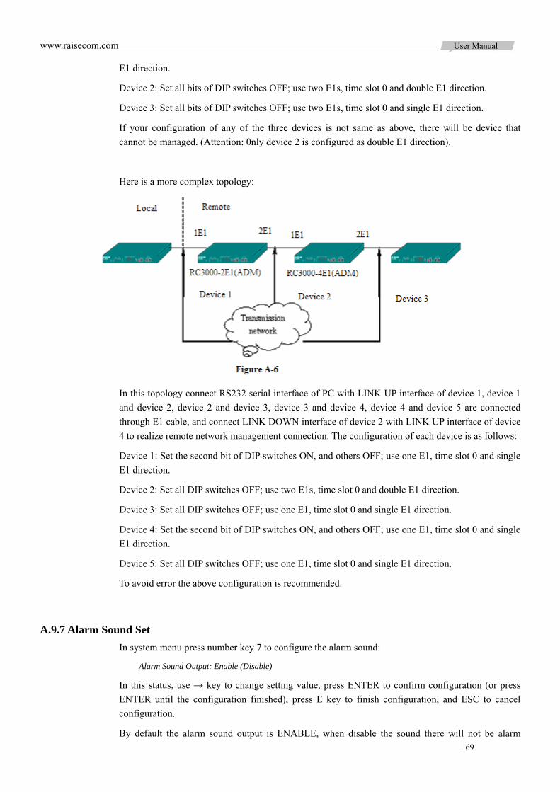
www.raisecom.com User Manual
69
E1 direction.
Device 2: Set all bits of DIP switches OFF; use two E1s, time slot 0 and double E1 direction.
Device 3: Set all bits of DIP switches OFF; use two E1s, time slot 0 and single E1 direction.
If your configuration of any of the three devices is not same as above, there will be device that cannot be managed. (Attention: 0nly device 2 is configured as double E1 direction).
Here is a more complex topology:
In this topology connect RS232 serial interface of PC with LINK UP interface of device 1, device 1 and device 2, device 2 and device 3, device 3 and device 4, device 4 and device 5 are connected through E1 cable, and connect LINK DOWN interface of device 2 with LINK UP interface of device 4 to realize remote network management connection. The configuration of each device is as follows:
Device 1: Set the second bit of DIP switches ON, and others OFF; use one E1, time slot 0 and single E1 direction.
Device 2: Set all DIP switches OFF; use two E1s, time slot 0 and double E1 direction.
Device 3: Set all DIP switches OFF; use one E1, time slot 0 and single E1 direction.
Device 4: Set the second bit of DIP switches ON, and others OFF; use one E1, time slot 0 and single E1 direction.
Device 5: Set all DIP switches OFF; use one E1, time slot 0 and single E1 direction.
To avoid error the above configuration is recommended.
A.9.7 Alarm Sound Set In system menu press number key 7 to configure the alarm sound:
Alarm Sound Output: Enable (Disable)
In this status, use → key to change setting value, press ENTER to confirm configuration (or press ENTER until the configuration finished), press E key to finish configuration, and ESC to cancel configuration.
By default the alarm sound output is ENABLE, when disable the sound there will not be alarm
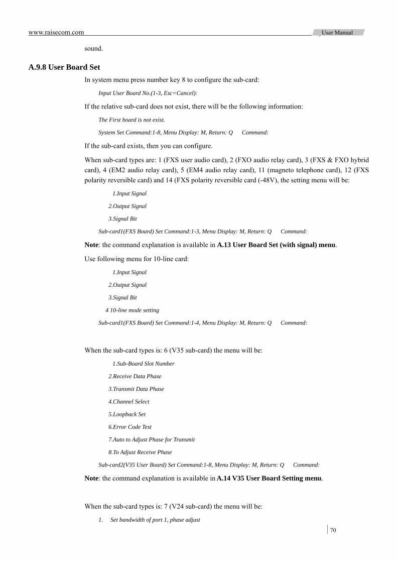
www.raisecom.com User Manual
70
sound.
A.9.8 User Board Set In system menu press number key 8 to configure the sub-card:
Input User Board No.(1-3, Esc=Cancel):
If the relative sub-card does not exist, there will be the following information:
The First board is not exist.
System Set Command:1-8, Menu Display: M, Return: Q Command:
If the sub-card exists, then you can configure.
When sub-card types are: 1 (FXS user audio card), 2 (FXO audio relay card), 3 (FXS & FXO hybrid card), 4 (EM2 audio relay card), 5 (EM4 audio relay card), 11 (magneto telephone card), 12 (FXS polarity reversible card) and 14 (FXS polarity reversible card (-48V), the setting menu will be:
1.Input Signal
2.Output Signal
3.Signal Bit
Sub-card1(FXS Board) Set Command:1-3, Menu Display: M, Return: Q Command:
Note: the command explanation is available in A.13 User Board Set (with signal) menu.
Use following menu for 10-line card:
1.Input Signal
2.Output Signal
3.Signal Bit
4 10-line mode setting
Sub-card1(FXS Board) Set Command:1-4, Menu Display: M, Return: Q Command:
When the sub-card types is: 6 (V35 sub-card) the menu will be:
1.Sub-Board Slot Number
2.Receive Data Phase
3.Transmit Data Phase
4.Channel Select
5.Loopback Set
6.Error Code Test
7.Auto to Adjust Phase for Transmit
8.To Adjust Receive Phase
Sub-card2(V35 User Board) Set Command:1-8, Menu Display: M, Return: Q Command:
Note: the command explanation is available in A.14 V35 User Board Setting menu.
When the sub-card types is: 7 (V24 sub-card) the menu will be:
1. Set bandwidth of port 1, phase adjust
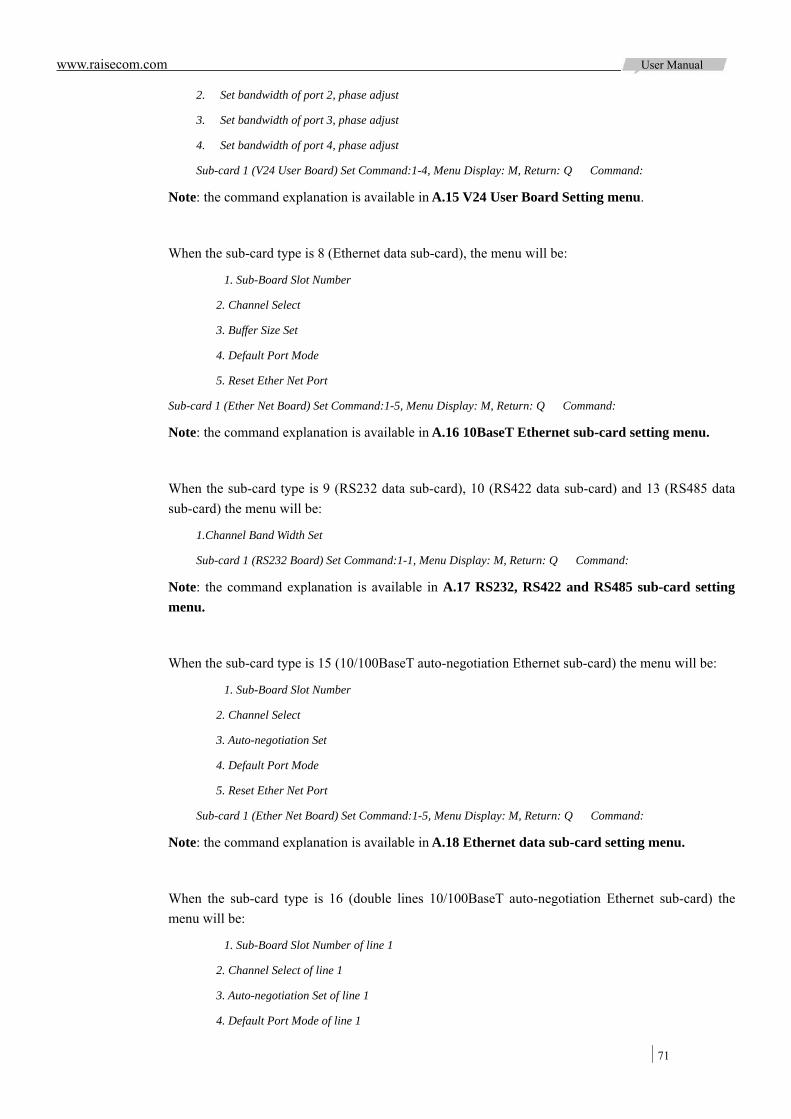
www.raisecom.com User Manual
71
2. Set bandwidth of port 2, phase adjust
3. Set bandwidth of port 3, phase adjust
4. Set bandwidth of port 4, phase adjust
Sub-card 1 (V24 User Board) Set Command:1-4, Menu Display: M, Return: Q Command:
Note: the command explanation is available in A.15 V24 User Board Setting menu.
When the sub-card type is 8 (Ethernet data sub-card), the menu will be:
1. Sub-Board Slot Number
2. Channel Select
3. Buffer Size Set
4. Default Port Mode
5. Reset Ether Net Port
Sub-card 1 (Ether Net Board) Set Command:1-5, Menu Display: M, Return: Q Command:
Note: the command explanation is available in A.16 10BaseT Ethernet sub-card setting menu.
When the sub-card type is 9 (RS232 data sub-card), 10 (RS422 data sub-card) and 13 (RS485 data sub-card) the menu will be:
1.Channel Band Width Set
Sub-card 1 (RS232 Board) Set Command:1-1, Menu Display: M, Return: Q Command:
Note: the command explanation is available in A.17 RS232, RS422 and RS485 sub-card setting menu.
When the sub-card type is 15 (10/100BaseT auto-negotiation Ethernet sub-card) the menu will be:
1. Sub-Board Slot Number
2. Channel Select
3. Auto-negotiation Set
4. Default Port Mode
5. Reset Ether Net Port
Sub-card 1 (Ether Net Board) Set Command:1-5, Menu Display: M, Return: Q Command:
Note: the command explanation is available in A.18 Ethernet data sub-card setting menu.
When the sub-card type is 16 (double lines 10/100BaseT auto-negotiation Ethernet sub-card) the menu will be:
1. Sub-Board Slot Number of line 1
2. Channel Select of line 1
3. Auto-negotiation Set of line 1
4. Default Port Mode of line 1
www.raisecom.com User Manual
72
5. Sub-Board Slot Number of line 2
6. Channel Select of line 2
7. Auto-negotiation Set of line 2
8. Default Port Mode of line 2
9. Reset Ether Net Port
Sub-card 1 (double lines Ether Net Board) Set Command:1-9, Menu Display: M, Return: Q Command:
Note: the command explanation is available in A.19 Ethernet data sub-card setting menu.
The showing menu for the other type of sub-card may be developed in future:
1. Sub-card time slot number
2. Mode 0 Set
3. Mode 1 Set
4. Byte 1 Set
5. Byte 2 Set
Sub-card 1 (unnamed board) Set Command:1-5, Menu Display: M, Return: Q Command:
Note: the command explanation is available in A.20 Undefined sub-card Set.
A.9.9 DCD and CTS of V35V24 Board with Alarm Set In System Setting menu press number key 9 to configure the alarm correlation of DCD & CTS:
With Alarm Set: Enable
In this status use → key to change the configured value; Press ENTER to confirm configuration, press E key to finish configuration, and ESC to cancel configuration.
When disable alarm correlation function, if the output status of DCD & CTS is normal the V35 board will transmit data and remote DTE device does not need to reset all the time; when enable alarm correlation function, if there are alarms of LOS, LOF and AIS, status of DCD will be unready and if there is RAL alarm status of CTS will be unready.
A.10 Line Board Setting menu
This section we will explain how to configure RC3000-OPT line-board and you must first enter the Line Board Setting menu.
A.10.1 Alarm Mask Set In optical line-board setting menu press number key 1 to configure optical alarm mask:
Optical Alarm Mask Set:
Local Optical Loss: Mask (Enable)
In this status use → key to disable or enable alarm mask; use ↓↑to change items (alarms); Press ENTER to confirm configuration, press E key to finish configuration, and ESC to cancel
www.raisecom.com User Manual
73
configuration.
The alarms are:
Local Optical Loss; Local LOF; Local E-3 ERR; Local E-6 ERR;
Remote Optical Loss; Remote LOF; Remote E-3 ERR; Remote E-6 ERR
A.10.2 Loopback Set In optical line-board setting menu press number key 2 to configure loopback of optical line:
Optical Loopback Set:
Loopback Direction: Remote
In this status use → key to change configured value (local/remote or enable/disable); use ↓↑ to change configuration items; Press ENTER to confirm configuration, press E key to finish configuration, and ESC to cancel configuration.
The configuration items are:
Loopback Direction; 1E1 Loopback; 2E1 Loopback; 3E1 Loopback; 4E1 Loopback
A.10.3 ALS Set In optical line-board setting menu press number key 3 to configure ALS function (the precondition is optical module has this function):
ALS function: Enable
In this status use → key to change configured value (enable or disable); Press ENTER to confirm configuration, press E key to finish configuration, and ESC to cancel configuration.
If the optical module does not have this function there will be prompt:
Optical Model hasn't ALS function, Can't be set.
Optical Board (Ethernet) Set Command:1-7, Menu Display: M, Return: Q Command:
A.10.4 Ether Net Port Set In optical line-board setting menu press number key 4 to configure Ethernet interface:
Ether Net Port: Open
In this status use → key to change configured value (open or close); Press ENTER to confirm configuration, press E key to finish configuration, and ESC to cancel configuration.
A.10.5 Ether Net Port Work Set In optical line-board setting menu press number key 5 to configure Ethernet interface work status:
Ether Net Work State Set:
Auto Mode: Enable
In this status use → key to change configured value (enable or disable); use ↓↑ to change
www.raisecom.com User Manual
74
configuration items; Press ENTER to confirm configuration, press E key to finish configuration, and ESC to cancel configuration.
The configuration items are: Auto Mode: Enable/Disable
Port Speed: 100M/10M
Port Mode: Full Duplex/Half Duplex
AUTO-MDI/MDIX: Enable/Disable
A.10.6 Transmit Band Width Set In optical line-board setting menu press number key 6 to configure Ethernet interface Tx Band Width:
Transmit Band Width: 4095 x 32Kbps
Set (0-4095):
The first row is present configuration value and the second row is for your configuration.
If you do not set bandwidth value in the second row and just press ENTER, the old configuration will be reserved. If you set the bandwidth value (the entering can only be number and within the range of 0-4095) and press ENTER, the new configuration will be effective. BackSpace key is available to modify the input value.
A.10.7 Receive Band Width Set In optical line-board setting menu press number key 7 configure Ethernet interface Rx Bandwidth:
Receive Band Width:4095 x 32Kbps
Set(0-4095):
The first row is present configuration value and the second row is for your configuration.
If you do not set bandwidth value in the second row and just press ENTER, the old configuration will be reserved. If you set the bandwidth value (the entering can only be number and within the range of 0-4095) and press ENTER, the new configuration will be effective. BackSpace key is available to modify the input value.
A.10.8 Reset Ether Net In optical line-board setting menu press number key 8 to reset the Ethernet interface:
To run this command will reset Ethernet port.
Run this command (Y/N):
Press Y key to confirm the operation and press N key to return, others keys are invalid.
A.11 2E1 Setting menu
This section is explanation of 2E1 setting, the content displays after enter line-card setting from
www.raisecom.com User Manual
75
system setting menu.
A.11.1 Alarm Mask Set Press command 1 in 2E1 line-card menu and enter optical port alarm mask setting:
Alarm mask set:
Local LOS: Mask (Enable)
In this situation, use → key to shift between enable and mask; use ↓ ↑ keys to shift the alarm items; ENTER key and E key mean to confirm alarm mask setting and exit; Esc key will cancel the input and exit.
The alarms contain:
Local LOS; Local LOF; Local E-3 ERROR;
Local E-6 ERROR; Local 3E1 LOS; Local 4E1 LOS;
Remote LOS; Remote LOF; Remote E-3 ERROR;
Remote E-6 ERROR; Remote 3E1 LOS; Remote 4E1 LOS.
A.11.2 Loopback Set Press command 2 in 2E1 line-card menu and enter loopback setting:
Loopback Set:
Loopback direction: Remote
In this situation, use → key to change setting value: Remote or Local, Enable or Disable; use ↓ ↑ keys to shift setting items; ENTER key and E key mean to confirm setting and exit; Esc key will cancel the input and exit.
The setting of this command includes:
Loopback direction, 1E1 Loop; 2E1 Loop; 3E1 Loop; 4E1 Loop.
A.11.3 ALS Enable Set Press command 3 in 2E1 line-card menu and enter ALS Enable setting. This function is not available until the optical head occupy this function:
ALS function: Enable
In this situation, use → key to change setting value: Enable or Disable; ENTER key and E key mean to confirm setting and exit; Esc key will cancel the input and exit.
The setting of this command is not available if the optical head doesn’t occupy this function:
The optical module does not have this ALS, the setting is unavailable.
2E1 Set Commands: 1-7 Show Menu: M Return: Q Commands:
www.raisecom.com User Manual
76
A.12 E1 Set
This section will explain the command in E1 Setting menu.
A.12.1 Use Set In E1 Setting menu press number key 1 to configure the E1 using status:
First E1: Using
In this status use → key to shift configured value: Enable or Disable; use ↓↑ to change configuration items; Press ENTER to confirm configuration, press E key to finish configuration, and ESC to cancel configuration.
Configuration items are: First E1; Second E1; Third E1 and Fourth E1.
A.12.2 Mode Set In E1 Setting menu press number key 2 to configure the E1 frame structure:
First E1 Mode: PCM30
In this status use → key to change E1 frame format: PCM30 or PCM31; use ↓ ↑ to change configuration items; Press ENTER to confirm configuration, press E key to finish configuration, and ESC to cancel configuration.
Configuration items are: First E1 Mode, Second E1 Mode, Third E1 Mode and Fourth E1 Mode
A.12.3 Mask Set In E1 Setting menu press number key 3 to configure alarm mask:
First E1:(Enable)
In this status use → key to change E1 alarm mask (enable or mask); use ↓ ↑ to change configuration items; Press ENTER to confirm configuration, press E key to finish configuration, and ESC to cancel configuration.
Configuration items are:
First E1; First E1 LOS; First E1 AIS; First E1 LOF
First E1 RAL; First E1 LOMF; First E1 CRC LOMF
First E1 CRC Alarm
Second E1; Second E1 LOS; Second E1 AIS; Second E1 LOF
Second E1 RAL; Second E1 LOMF; Second E1 CRC LOMF
Second E1 CRC Alarm
Third E1; Third E1 LOS; Third E1 AIS; Third E1 LOF
Third E1 RAL; Third E1 LOMF; Third E1 CRC LOMF
Third E1 CRC Alarm
www.raisecom.com User Manual
77
Fourth E1; Fourth E1 LOS; Fourth E1 AIS; Fourth E1 LOF
Fourth E1 RAL; Fourth E1 LOMF; Fourth E1 CRC LOMF
Fourth E1 CRC Alarm
Note: if the line-card is 2E1 line-card only 2 E1 can be configured.
A.12.4 CRC Set In E1 Setting menu press number key 4 to configure CRC check function:
CRC Set: Enable
In this status use → key to change the configured value: Enable or disable; Press ENTER to confirm configuration, press E key to finish configuration, and ESC to cancel configuration.
A.13 User Card Set (with signal) menu
This section will explain the command of User Card Set (with signal configuration) menu, including: FXS user audio card RC3000-SUB-DS, FXO audio relay card RC3000-SUB-DO, FXS & FXO hybrid user card RC3000-SUB-DSO, E&M2 audio relay card RC3000-SUB-DM2, E&M4 audio relay card RC3000-SUB-DM4 and magneto telephone card RC3000-SUB-DMT.
A.13.1 Input Signal In user board setting menu press number key 1 to configure Rx signal:
User Card Signal In: Original
In this status use → key to change the configured value: Original or Reversal; Press ENTER to confirm configuration, press E key to finish configuration, and ESC to cancel configuration.
Note: the Original indicates the default signal mode of RC3000, Reversal indicates the reverse mode of RC3000 default signal mode. Default signal mode of RC3000 is: high-voltage ring and off-hook.
A.13.2 Output Signal In user card setting menu press number key 2 to configure Tx signal mode:
User Card Signal Out: Original
In this status use → key to change the configured value: Original or Anti; Press ENTER to confirm configuration, press E key to finish configuration, and ESC to cancel configuration.
A.13.3 Signal Bit In user board setting menu press number key 3 to configure the signal bit:
First Channel Signal Bit: A
In this status use → key to change signal bit: A or B; use ↓ ↑ to change configuration items; Press ENTER to confirm configuration, press E key to finish configuration, and ESC to cancel
www.raisecom.com User Manual
78
configuration.
Configuration items are:
First Channel Signal Bit; Second Channel Signal Bit; Third Channel Signal Bit…
Last Channel Signal Bit
A.13.4 10-line mode In the menu item on 10-line card, press command 4 to enter the 10-line mode setting, shown as below: 10-line mode: enable
In this state, to change the settings via the → key: enable or disable; <Enter> key and the <E> key indicate that setting is completed, exit the setting; press <Esc> key to cancel the input, exit the settings.
Note: For card that does not support 10-line model, there is no content for this command.
A.14 V35 User Card Setting menu
This section explains how to configure V35 user card.
A.14.1 Sub-card Slot Number In V35 user card setting menu press number key 1 to configure the occupied channel number:
User Card Slot Number=8
Input Slot Number (0-31):
The first row displays present configuration value and the second row is for your new configuration.
If you do not set occupied channel number in the second row and just press ENTER, the old configuration will be reserved. If you set the occupied channel number (the entering can only be number and within the range of 0-31) and press ENTER, the new configuration will be effective. BackSpace key is available to modify.
RC3000-SUB-DV35 is a data card with V35 interface and the channel number is configurable, the rules are as follow:
a. V35 sub-card can transmit data in two ways: use main cross group & use single cross group. The first user E1 is a main cross group and channels of this cross group will be distributed to user cards. Other user E1s are single cross group for different slots: For MCU versions lower than REV.A.2 (including REV.A.2): user card in first slot will occupy cross group 6 (user E1 2) and user card in second slot will occupy cross group 8 (user E1 4), user card in the third slot does not have single cross group. For MCU versions are advanced than REVA.2: user card in first slot will occupy cross group 6 (user E1 2) and user card in second slot will occupy cross group 7 (user E1 3), user card in the third slot will occupy cross group 87 (user E1 4). The use channel should be set before setting cross group.
b. The number of occupied channels for V35 user board is limited. Limitation for single cross group: Channel number range is 0-31, 0 indicates nonuse; the startup channel is channel 1 and there will not be channel occupation collision alarms. And limitation for main cross group (user E1 1) is: when
www.raisecom.com User Manual
79
V35 sub-card uses main cross group to transfer data the number of channels will not same for different slots. Channel number range for first slot is 0-31, 0 indicates that shutdown the transmission, and the startup channel is channel 1. If other slots have already occupied the channels of main cross group there will alarms. Channel number range for second slot is 0-23, 0 indicates that shutdown the transmission, and the startup channel is channel 9. If other slots have already occupied the channels of main cross group there will alarms. Channel number range for the third slot is 0-15, 0 indicates that shutdown the transmission of this user card, and the startup channel is channel 17.
A.14.2 Receive Data Phase In V35 user board setting menu press number key 2 to configure Rx data phase:
Receive Data Phase: Positive
In this status use → key to change the configured value: Positive or Negative; Press ENTER to confirm configuration, press E key to finish configuration, and ESC to cancel configuration.
Note: the Positive indicates the default output data phase of V35, Negative indicates the reverse value of default data phase.
A.14.3 Transmit Data Phase In V35 user board setting menu press number key 3 to configure Tx data phase:
Transmit Data Phase: Positive
In this status use → key to change the configured value: Positive or Negative; Press ENTER to confirm configuration, press E key to finish configuration, and ESC to cancel configuration.
A.14.4 Channel Select In V35 user card setting menu press number key 4 to select data channel:
Data Channel Select: Main Channel
In this status use → key to change the configured value: Main channel or Single channel; Press ENTER to confirm configuration, press E key to finish configuration, and ESC to cancel configuration.
A.14.5 Loopback Set In V35 user board setting menu press number key 5 to configure loopback status of V35 user board:
Local Loopback Set:No Loopback
In this status use → key to change loopback status; use ↓ ↑ to change configuration items; Press ENTER to confirm configuration, press E key to finish configuration, and ESC to cancel configuration.
Configuration items are: Local internal Loopback & Local external Loopback.
Note: Local internal loopback indicates the data loopback from V35 to V35 and Local external Loopback indicates the data loopback from V35 to E1.
www.raisecom.com User Manual
80
A.14.6 Error Code Test In V35 user board setting menu press number key 6 to configure Error bit test:
Error Bit Test: Enable
In this status use → key to change the configured value: Disable or Enable; Press ENTER to confirm configuration, press E key to finish configuration, and ESC to cancel configuration.
Note: when you start error code test, V35 user card will transmit error bit periodically, and its Rx will test the Rx data. If the Rx error bit is same with that of Tx, error bit test indicator light (PAT_OK) will ON, otherwise the light will flickering or OFF.
A.14.7 Auto to Adjust Phase for Transmit In V35 user board setting menu press number key 7 to configure the Tx data Phase Auto Adjust function:
Auto to Adjust Phase for Transmit: Enable
In this status use → key to change the configured value: Disable or Enable; Press ENTER to confirm configuration, press E key to finish configuration, and ESC to cancel configuration.
Note: V35 sub-card can adjust the phase of Tx data automatically.
A.14.8 To Adjust Receive Phase In V35 user board setting menu press number key 8 to configure the Rx data phase adjust function:
To Adjust Receive Phase: Enable
In this status use → key to change the configured value: Disable or Enable; Press ENTER to confirm configuration, press E key to finish configuration, and ESC to cancel configuration.
Note: V35 sub-card can adjust Rx data with a 0-degree shift, 90-degree shift and 180-degree shift. Disable this function and set the Rx data phase positive: the Rx data phase will be 0 degree; disable this function and set the Rx data phase negative: the Rx data phase will be 180 degree; enable this function and set the Rx data phase positive: the Rx data phase will be 90 degree.
A.15 V24 User Card Set
Press number key 1 to configure port 1:
Port 1 Set:
Bandwidth: 64kbps
In this status use → key to change set value; use ↓↑to swich the content; press ENTER to confirm configuration, press E key to finish configuration, and ESC to cancel configuration.
Configuration items are:
Bandwidth: 64kbps or 128kbps
Receive phase adjust: Positive, Negative
www.raisecom.com User Manual
81
Transmit phase adjust: Positive, Negative
A.16 10BaseT Ethernet sub-card setting menu
This section will explain how to configure Ethernet data sub-card.
A.16.1 Sub-Board Slot Number In Ethernet sub-card setting menu press number key 1 to configure the number of occupied channels:
User Card Slot Number=8
Input Slot Number(0-31):
The first row displays present configuration value and the second row is for your new configuration.
If you do not set occupied channel number in the second row and just press ENTER, the old configuration will be reserved. If you set the occupied channel number (the entering must within the range of 0-31) and press ENTER, the new configuration will be effective. BackSpace key is available to modify.
The rule of configuring channels is the same as that of V35, please refer to the relative section of V35 sub-card set.
A.16.2 Channel Select In Ethernet user board setting menu press number key 2 to select data channel:
Data Channel Select: Main Channel
In this status use → key to change the configured value: Main channel or Single channel; Press ENTER to confirm configuration, press E key to finish configuration, and ESC to cancel configuration.
A.16.3 Buffer Size Set In Ethernet user board setting menu press number key 3 to set the buffer size:
Buffer Size Set:>256Kbps
In this status use → key to change the configured value: >=2Mbps, >1Mbps, >512Kbps, >256Kbps; Press ENTER to confirm configuration, press E key to finish configuration, and ESC to cancel configuration.
Note: Buffer size set is aim to deduce time-delay in receiving and transmitting data, the delay reaches minimum value when buffer size is the same as occupied channels.
A.16.4 Default Port Mode In Ethernet user card setting menu press number key 4 to set the default port mode:
Default Port Model: Full Duplex

www.raisecom.com User Manual
82
In this status use → key to change the configured value: Full duplex or Half duplex; Press ENTER to confirm configuration, press E key to finish configuration, and ESC to cancel configuration.
Note: Default port mode refers to the mode when Ethernet electric interface is LINK DOWN, and when Ethernet electric interface is LINK UP it is in auto negotiation mode.
A.16.5 Reset Ethernet Port In Ethernet user board setting menu press number key 5 to reset the Ethernet electric interface and there will be the confirm prompt:
To run this command will reset Ethernet port.
Run this command (Y/N):
In this status press Y to reset the board and press N to cancel the operation. Other entering are invalid.
A.17 RS232, RS422 and RS485 sub-card setting menu
This section will explain the commands of RS232, RS422 and RS485 sub-card menu.
A.17.1 Channel Band Width Set In user card setting menu press number key 1to configure channel band width::
Channel Band Width:64Kbps
In this status use → key to change the configured value: 64Kbps, 128Kbps; Press ENTER to confirm configuration, press E key to finish configuration, and ESC to cancel configuration.
Note: Bandwidth set of RS232, RS422 and RS485 has not been fully realized now, and this function is reserved.
A.18 10/100BaseT auto-negotiation Ethernet sub-card Setting menu
A.18.1 Sub-Board Slot Number In Ethernet sub-card setting menu press number key 1 to configure the number of occupied channels:
User Card Slot Number=8
Input Slot Number(0-31):
The first row displays present configuration value and the second row is for your new configuration.
If you do not set occupied channel number in the second row and just press ENTER, the old configuration will be reserved. If you set the occupied channel number (the entering must within the range of 0-31) and press ENTER, the new configuration will be effective. BackSpace key is available to modify.
The rule of configuring channels is the same as that of V35, please refer to the relative section of V35 sub-card set.
www.raisecom.com User Manual
83
A.18.2 Channel Select In Ethernet user board setting menu press number key 2 to select data channel:
Data Channel Select: Main Channel
In this status use → key to change the configured value: Main channel or Single channel; Press ENTER to confirm configuration, press E key to finish configuration, and ESC to cancel configuration.
A.18.3 Auto-negotiation Set In Ethernet user card setting menu press number key 3:
Auto-negotiation: Enable
In this status use → key to change the configured value; Press ENTER to confirm configuration, press E key to finish configuration, and ESC to cancel configuration. The configuration items are Enable and Disable.
A.18.4 Default Port Mode In Ethernet user card setting menu press number key 4 to set the default port mode:
Default Port Mode: Full Duplex
In this status use → key to change the configured value: Full duplex or Half duplex; Press ENTER to confirm configuration, press E key to finish configuration, and ESC to cancel configuration.
Note: Default port mode refers to the mode when Ethernet electric interface is LINK DOWN, and when Ethernet electric interface is LINK UP it is in auto-negotiation mode.
A.18.5 Reset Ethernet Port In Ethernet user board setting menu press number key 5 to reset the Ethernet electric interface and the confirming prompt will be there:
To run this command will reset Ethernet port.
Run this command (Y/N):
In this status press Y to reset the board and press N to cancel the operation. Other entering are invalid.
A.19 Double-line 10/100BaseT auto-negotiation Ethernet sub-card Setting menu
This section will explain the commands of double lines 10/100BaseT auto-negotiation Ethernet sub-card setting menu.

www.raisecom.com User Manual
84
A.19.1 Timeslot Set of the first Ethernet line In Ethernet sub-card setting menu press number key 1 to configure the number of occupied channels:
User Card Slot Number=8
Input Slot Number(0-31):
The first row displays present configuration value and the second row is for your new configuration.
If you do not set occupied channel number in the second row and just press ENTER, the old configuration will be reserved. If you set the occupied channel number (the entering must within the range of 0-31) and press ENTER, the new configuration will be effective. BackSpace key is available to modify.
The rule of configuring channels is the same as that of V35, please refer to the relative section of V35 sub-card set.
A.19.2 Channel selection of the first Ethernet line In Ethernet user board setting menu press number key 2 to select data channel:
Data Channel Select of the first Ethernet line: Main Channel (Single channel)
In this status use → key to change the configured value: Main channel or Single channel; Press ENTER to confirm configuration, press E key to finish configuration, and ESC to cancel configuration.
A.19.3 Auto-negotiation Set of the first Ethernet line In Ethernet user card setting menu press number key 3:
Auto-negotiation of the first Ethernet line: Enable
In this status use → key to change the configured value; Press ENTER to confirm configuration, press E key to finish configuration, and ESC to cancel configuration. The configuration items are Enable and Disable.
A.19.4 Default port mode of the first Ethernet line In Ethernet user card setting menu press number key 4 to set the default port mode:
Default Port Mode of the first Ethernet line: 100M Full Duplex
In this status use → key to change the configured value: 10M Half duplex, 10M Full duplex, 100M Half duplex and 100M Full duplex; Press ENTER to confirm configuration, press E key to finish configuration, and ESC to cancel configuration.
Note: Default port mode refers to the mode when Ethernet electric interface is LINK DOWN, and when Ethernet electric interface is LINK UP it is in auto-negotiation mode.
A.19.5 Timeslot Set of the second Ethernet line In Ethernet sub-card setting menu press number key 1 to configure the number of occupied channels:
www.raisecom.com User Manual
85
User Card Slot Number=8
Input Slot Number(0-31):
The first row displays present configuration value and the second row is for your new configuration.
If you do not set occupied channel number in the second row and just press ENTER, the old configuration will be reserved. If you set the occupied channel number (the entering must within the range of 0-31) and press ENTER, the new configuration will be effective. BackSpace key is available to modify.
The rule of configuring channels is the same as that of V35, please refer to the relative section of V35 sub-card set.
A.19.6 Channel selection of the second Ethernet line In Ethernet user board setting menu press number key 2 to select data channel:
Data Channel Select of the second Ethernet line: Main Channel (Single channel)
In this status use → key to change the configured value: Main channel or Single channel; Press ENTER to confirm configuration, press E key to finish configuration, and ESC to cancel configuration.
A.19.7 Auto-negotiation Set of the second Ethernet line In Ethernet user card setting menu press number key 3:
Auto-negotiation of the second Ethernet line: Enable
In this status use → key to change the configured value; Press ENTER to confirm configuration, press E key to finish configuration, and ESC to cancel configuration. The configuration items are Enable and Disable.
A.19.8 Default port mode of the first Ethernet line In Ethernet user card setting menu press number key 4 to set the default port mode:
Default Port Mode of the second Ethernet line: 100M Full Duplex
In this status use → key to change the configured value: 10M Half duplex, 10M Full duplex, 100M Half duplex and 100M Full duplex; Press ENTER to confirm configuration, press E key to finish configuration, and ESC to cancel configuration.
Note: Default port mode refers to the mode when Ethernet electric interface is LINK DOWN, and when Ethernet electric interface is LINK UP it is in auto-negotiation mode.
A.19.9 Reset Ethernet port In Ethernet user board setting menu press number key 5 to reset the Ethernet electric interface and the confirming prompt will be there:
To run this command will reset Ethernet port.
www.raisecom.com User Manual
86
Run this command (Y/N):
In this status press Y to reset the board and press N to cancel the operation. Other entering are invalid.
Note: The two lines of double-line Ethernet sub-card can occupy the same STBUS or occupy different STBUS. When input occupied timeslots, the total timeslots number is calculated by automation and there is prompt at the place where the timeslot number can be input. Illegal input number will not run or not read by system. Port reset function will reset both the two ports at the same time.
A.20 DC64K sub-card Set
A.20.1 Alarm mask set In settings menu item on DC64K user sub-card, press command 1 to enter the card alarm mask, shown as below: Alarm mask setting on port 1: disable
In this state, change the settings value via the → key: enable or disable; change the port value via the ↑ key: increment of the cyclic forms; change the port value via the ↓ key: decrement of the cyclic forms. If press <Enter> key and <E> key, the new setting value will be recorded; if press <Esc> key to cancel the input, exit the settings at any time.
A.20.2 Port loopback setting In settings menu item on DC64K user sub-card, press command 2 to enter the port loop back setting, shown as below: loop back setting on port 1: no loopback In this state, change the settings value via the → key, outer-loop, inner-loop and no loopback; change the port value via the ↑ key: increment of the cyclic forms; change the port value via the ↓ key: decrement of the cyclic forms. If press <Enter> key and <E> key, the new setting value will be recorded; if press <Esc> key to cancel the input, exit the settings at any time.
A.20.3 Error Test In settings menu item on DC64K user sub-card, press command 3 to enter the card error test, is shown below:
Error bit test: disable
In the error bit test state, change the settings value via the → key to: enable or disable. switch between Error bit testing and testing port via the↑key and the↓key.
In the test port state, change the port value via the → key: increment of the cyclic forms. <Enter> key and <E> key indicate that the setting is complete, exit the setting; press <Esc> key to cancel the input, exit the settings.
Note: The internal non-bit ester supports only one line data test error.
When line under tested using the internal error, line under test is necessary to form a closed ring, so that can be tested, or can not be tested; test environment is as shown below. After the
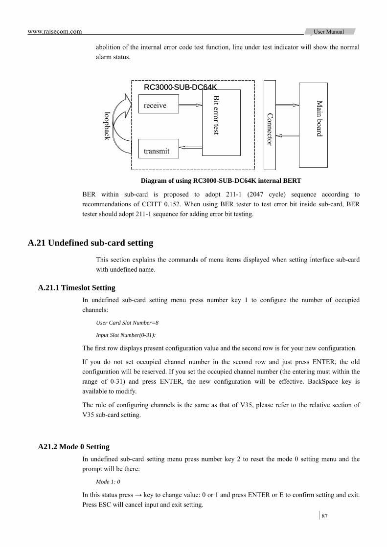
www.raisecom.com User Manual
87
abolition of the internal error code test function, line under test indicator will show the normal alarm status.
Diagram of using RC3000-SUB-DC64K internal BERT
BER within sub-card is proposed to adopt 211-1 (2047 cycle) sequence according to recommendations of CCITT 0.152. When using BER tester to test error bit inside sub-card, BER tester should adopt 211-1 sequence for adding error bit testing.
A.21 Undefined sub-card setting
This section explains the commands of menu items displayed when setting interface sub-card with undefined name.
A.21.1 Timeslot Setting In undefined sub-card setting menu press number key 1 to configure the number of occupied channels:
User Card Slot Number=8
Input Slot Number(0-31):
The first row displays present configuration value and the second row is for your new configuration.
If you do not set occupied channel number in the second row and just press ENTER, the old configuration will be reserved. If you set the occupied channel number (the entering must within the range of 0-31) and press ENTER, the new configuration will be effective. BackSpace key is available to modify.
The rule of configuring channels is the same as that of V35, please refer to the relative section of V35 sub-card setting.
A21.2 Mode 0 Setting In undefined sub-card setting menu press number key 2 to reset the mode 0 setting menu and the prompt will be there:
Mode 1: 0
In this status press → key to change value: 0 or 1 and press ENTER or E to confirm setting and exit. Press ESC will cancel input and exit setting.
receive
transmit
Bit error test
Connector
RC3000-SUB-DC64K
loopback
Main board
RC3000-SUB-DC64K
www.raisecom.com User Manual
88
Note: Set at this section is equal to input signaling setting for signal card.
A21.3 Mode 1 Setting In undefined sub-card setting menu press number key 3 to reset the mode 1 setting menu and the prompt will be there:
Mode 1: 0
In this status press → key to change value: 0 or 1 and press ENTER or E to confirm setting and exit. Press ESC will cancel input and exit setting.
Note: Set at this section is equal to output signaling set for signal card.
A21.4 Byte 1 Set In undefined sub-card setting menu press number key 4 to reset the byte 1 setting menu and the prompt will be there:
Byte 1 (Set value=0 0 0 0 0 0 0 0 ):
For byte with different sub-card type, the setting items are different. Refer to setting items of different types of sub-card to set the byte.
If users don’t input number and press ENTER key direct, the old set will be saved and enter the next byte mode set. Once input some items, the command will take efficient after finish all items input.
End with ENTER for input one byte to confirm, press E key indicates finish input and save the former input setting. Press ESC at anytime will cancel the set.
Note: Input of this section is equal to signal bit input of signal sub-card.
A21.5 Byte 2 Set In undefined sub-card setting menu press number key 5 to reset the byte 2 setting menu and the prompt will be there:
Byte 2 (Set value=0 0 0 0 0 0 0 0 ):
For byte with different sub-card type, the setting items are different. Refer to setting items of different types of sub-card to set the byte.
If users don’t input number and press ENTER key direct, the old set will be saved and enter the next byte mode set. Once input some items, the command will take efficient after finish all items input.
End with ENTER for input one byte to confirm, press E key indicates finish input and save the former input setting. Press ESC at anytime will cancel the set.
Note: Input of this section is equal to input of reserved bytes set.
A.22 Cross Setting menu
In setting menu press number key 2 there will be Cross Setting menu:

www.raisecom.com User Manual
89
1.Cross Set
2.Create Group Cross
3.Delete Group Cross
Cross Set Command:1-3, Menu Display: M, Return: Q Command:
A.22.1 Cross Set In cross setting menu press number key 1 to configure the cross connect:
Input Group Number (1-8):
First input the cross group number, which should be number in range of 1-8. There are 8 cross connect data groups in RC3000 that divided into 4 E1s (1-4) and 4 user group (5-8):
First Channel:
There are two parts of configured data for each channel: a group number and a channel number (there must be space between the two numbers) such as: 1 1, 0 0 indicates deleting the cross connection of this channel. Press ENTER for the configuration of the next channel (for unfinished entering you cannot start to configure the next channel and the invalid data will be discarded).
Second Channel:
Press ENTER to confirm configuration (or skip that channel’s configuration and the old value will be reserved), press E key to finish configuration, and ESC to cancel configuration.
A.22.2 Create Group Cross In cross setting menu press number key 2 to create group cross:
Group No. for Time Slot Out:
The entering must be a number from 1 to 8, press ENTER to confirm and start the configuration of next item. The system will check the entered number, if invalid it will be discarded; if valid there will be next item configuration.
Time Slot Start No. for Time Slot Out:
The entering must be a number from 1 to 31, press ENTER to confirm and start the configuration of next item. The system will check the entered number; if invalid it will be discarded; if valid there will be next item configuration.
Group No. for Time Slot In:
The entering must be a number from 1 to 8, press ENTER to confirm and start the configuration of next item. The system will check the entered number; if invalid it will be discard; if valid there will be next item configuration.
Time Slot Start No. for Time Slot In:
The entering must be a number from 1 to 31, press ENTER to confirm and start the configuration of next item. The system will check the entered number; if invalid it will be discarded; if valid there will be next item configuration.
Time Slot Number for Create Cross:
The entering must be a number from 1 to 31, press ENTER to confirm and start the configuration of

www.raisecom.com User Manual
90
next item. The system will check the entered number; if invalid it will be discarded; if valid there will be next item configuration.
Create Mode: Uni-direction
In this status use → to change the configured value: Uni-direction & Bi-directional, press ENTER to confirm and start the configuration of next item.
Deal Mode for Old Relation Data: Retain
In this status use → to change the configured value: Retain & Clear, press ENTER to confirm.
In the configuration process press ESC to exist and the above configurations will be invalid.
(There are seven steps of this configuration: Group No. for Time Slot In, Time Slot Start No. for Time Slot In, Group No. for Time Slot Out, Time Slot Start No. for Time Slot Out, Time Slot Number for Create Cross, Create Mode: Bi-directional, Deal Mode for Old Relation Data)
Users can use these commands when set a continuous cross connect, for example the next cross connect is required:
Bi-direction cross connect the 1-5 channel of cross group 1 with 9-13 channels of cross group 5 (first user E1) and clear the old configurations, you can use these commands as:
Group No. for Time Slot Out:1
Time Slot Start No. for Time Slot Out:1
Group No. for Time Slot In:5
Time Slot Start No. for Time Slot In:9
Time Slot Number for Create Cross:5
Create Mode: Bi-direction
Deal Mode for Old Relation Data: Clear
Then the required cross connect will be set.
A.22.3 Delete Group Cross In cross setting menu press number key 3 to delete group cross:
Group No. for Delete Cross:
The entering must be a number from 1 to 8, press ENTER to confirm and start the configuration of next item. The system will check the entered number, if invalid it will be discarded; if valid there will be next item configuration.
Time Slot Start No. for Delete Cross:
The entering must be a number from 1 to 31, press ENTER to confirm and start the configuration of next item. The system will check the entered number; if invalid it will be discarded; if valid there will be next item configuration.
Time Slot Number for Delete Cross:
The entering must be a number from 1 to 31, press ENTER to confirm and start the configuration of next item. The system will check the entered number; if invalid it will be discarded; if valid there will be next item configuration.
Delete Relation: Retain
www.raisecom.com User Manual
91
In this status use → to change the configured value: Retain & Clear, presses ENTER to confirm, and the relative cross connect will be deleted.
(There are four steps of this configuration:, Group No. for Delete Cross, Time Slot Start No. for Delete Cross, Time Slot Number for Delete Cross, and Delete Relation: delete this group or delete both this group and the retain group.)
Users can use these commands when delete a continuous cross connect, for example the next cross connect is required:
Delete cross connect of cross group 1 1-5 channels and its correlation configuration:
Group No. for Delete Cross:1
Time Slot Start No. for Delete Cross:1
Time Slot Number for Delete Cross:5
Delete Relation: Clear
Then cross connect of cross group 1 1-5 channels and its correlation configuration will be deleted.
A.23 REV.A work mode Set
Press 3 in command Setting menu to enter REV.A work mode set:
Setting command:1-4, show menu: M; exit: Q; Command: 3
REV.A work mode set: Enable
In this status, use → key to change setting value: Enable or Disable. ENTER key and E key will confirm the setting and exit; ESC key will cancel input and exit the menu.
Support 10-line mode
In configure command menu, press 4 to enter to 10-line supporting modes, shown as below:
Set command:1-4, show menu: M, exit: Q command:4
10-line setting mode: enable
In this state, press→ key to change the setting value: enable or disable. Enter key and E keys indicate that the setting validation is complete, exit the setting; press Esc key to cancel the input, exit the settings.
10-line mode is a new function applied on RC3000-SUB-10FXS and RC3000-SUB-10FXO sub-card.
When enable this mode, RC3000-SUB-10FXS/10FXO sub-card can occupy 10 timeslots, when this mode disable, RC3000-SUB-10FXS/10FXO only occupy 8 timeslots, where 2 line of voice is unavailable.
A.25 Operate menu
In main menu press number key 6 there will be Operate menu:
1.System Reset
2.Mute
www.raisecom.com User Manual
92
3.Clear All Set
4.Clear Cross Set
5.Save Set Info
6.Make Default Set
7.Clear Reset and Board-Change Flag
8.Test Watchdog
9.Test EEPROM
Operate Command:1-9, Menu Display: M, Return: Q Command:
A.25.1 System Reset In operate menu press number key 1 to reset the system:
Run this command, the device will restart and need reinput password for enter console operating.
Run this command(Y/N):
Press Y to reset (system will be repowered on) and N to cancel.
A.25.2 Mute In operate menu press number key 2 to mute alarm sound once and there will not be any prompt.
A.25.3 Clear All Set In operate menu press number key 3 to clear all configurations:
Run this command, the device will format all data. System will be initialized.
Run this command (Y/N):
Press Y to start initialization and N to cancel.
Note: system initialization will set all configurations in 0 status, and parts restore to factory default value. All cross set will be cleared.
A.25.4 Clear Cross Set In operate menu press number key 4 to clear cross set:
Run this command, the device will format all cross data. All data will be nil.
Run this command(Y/N):
Press Y to start initializing all cross connect and N to cancel.
A.25.5 Save Set Info In operate menu press number key 5 to save all information in RAM to EEPROM.
www.raisecom.com User Manual
93
A.25.6 Make Default Set In operate menu press number key 6 to restore factory default value:
Run this command, the device will be first state from manufactory.
All saving data will loss. The device will restart.
Run this command(Y/N):
All information in EEPROM will be invalid if you press Y key, and press N key will exist. By default, except hardware version there is no information in EEPROM. So restore to factory default value is same as delete all saved information.
A.25.7 Clear Reset and Card-Change Flag In operate menu press number key 7 to clear flag information of resetting device and changing the card. And there is no prompt.
A.25.8 Test Watchdog In operate menu press number key 8 the check whether watchdog can reset CPU. Normally watchdog program will restart CPU, and in abnormal status the system cannot exist from closed-loop.
A.25.9 Test EEPROM In operate menu press number key 9 to test whether EEPROM can save data normally:
Normally there will be:
Can save data to EEPROM.
Abnormally there will be:
Can not save data to EEPROM.
A.26 Version
In main menu press number key 7 to get version information:
1.Display Version information
Version Information
Command: 1-1, Menu Display: M, Return: Q Command:
A.26.1 Display Version information In version menu press number key 1 to show device version information:
Hardware Version: REV A.01
Software Version: REV 1.1
PCB Version: REV A.3

www.raisecom.com User Manual
94
Version Information Command:1-1, Menu Display: M, Return: Q Command:
A.27 Console Setting menu
In main menu press number key 8 there will be console setting menu:
1.Language Select
2.Password Set
Console Set Command:1-2, Menu Display: M, Return: Q Command:
A.27.1 Language Select In console setting menu press number key 1 to select language:
Language Select: English
In this status use → key to change the language (English and Chinese), press ENTER to confirm.
A.27.2 Password Set In console setting menu press number key 2 to change the password:
Input Old Password:
Enter your password and press ENTER to confirm (there will be * prompt for each entered character). If the password is wrong, there will be:
Input password error or input illegal character.
If right, there will be:
Input New Password::
Enter your password and press ENTER for next entering:
Input New Password Again:
Enter your password and press ENTER to confirm (there will be * prompt for each entered character). If it is same with the last entered password, the password configuration will be successful; otherwise there will be the prompt:
Twice new password is not same, password setting failed.
Anytime press ESC to cancel and the control characters are invalid.
A.28 Quit
In main menu press number key 9 to exit console operation.
A.29 Hot key explanation
For console operation there are four hot keys:
Ctrl + L(l) change language

www.raisecom.com User Manual
95
Ctrl + R(r) force the device to reset, and there is no prompt
Ctrl + U(u) mute present alarm sound
Ctrl + Q(q) exit from console operation

Address: 2nd Floor, South Building of Rainbow Plaza, No.11 Shangdi Information Road, Haidian District, Beijing Postcode: 100085 Tel: +86-10-82883305 Fax: +86-10-82883056 Email: [email protected] http://www.raisecom.com