rc 0201 ip instructions manual 140410 - rivetnutusa.comip)_tool_manual.pdf · contact: cardinal...
TRANSCRIPT

Copyright © 2014 by Bollhoff Attexor S.A. Edition date: 2014-04-10
RIVCLINCH® 3201(IP)
User m anual
Origin al edition in english
Call Cardinal Components to Order or for Quote 800-236-3200 [email protected] www.rivet-nut.com

Copyright © 2014 by Bollhoff Attexor S.A. Page 2
Copyright and Trademarks This is a non-contractual document issued for information purposes only.
Specifications and dimensions are indicative only and are subject to changes without notice.
Information about technical performance, joint strength values and similar are given purely as indications and can in no way be interpreted as a guarantee for result in a specific application. Bollhoff Attexor S.A. disclaims all warranties either express or implied, including but not limited to, implied warranties of merchantability or fitness for a particular purpose of applications and hardware. In particular Bollhoff Attexor S.A. takes no responsibility of the performance of the joints on finished products.
This document Copyright© 2014 by Bollhoff Attexor S.A.,CH-1024 Ecublens/Lausanne, Switzerland. All rights reserved.
Machines and/or toolings from Bollhoff Attexor S.A. are protected by patents and/or pending patents worldwide.
Phone: 800-236-3200 E-mail: [email protected]
Call Cardinal Components to Order or for Quote 800-236-3200 [email protected] www.rivet-nut.com

Copyright © 2014 by Bollhoff Attexor S.A. Page 3
Table of contents
COPYRIGHT AND TRADEMARKS.............................................................................. 2
TABLE OF CONTENTS ............................................................................................... 3
WARRANTY ................................................................................................................. 5
WARNINGS .................................................................................................................. 6
TECHNICAL SPECIFICATIONS ................................................................................ 10
RIVCLINCH® 3201(IP) .............................................................................................. 10
FUNCTIONAL DESCRIPTION ................................................................................... 11
SINGLE-STROKE CLINCHING, OPENING DIE .................................................................... 11 CLINCHING SYSTEM, END-OF-STROKE (OR END-STOP) CONTROL..................................... 12
INSTALLATION, CONNECTIONS ............................................................................. 13
FIXING, SUSPENSION .................................................................................................. 13 CONNECTION............................................................................................................. 14
START-UP.................................................................................................................. 15
SETTINGS FOR START-UP OF THE CLINCHING SYSTEM .................................................... 15 USING OF THE CLINCHING MACHINE.............................................................................. 16
CARE AND MAINTENANCE ...................................................................................... 17
DAILY MAINTENANCE .................................................................................................. 17 WEEKLY MAINTENANCE .............................................................................................. 17 EVERY 500'000 CYCLES............................................................................................. 18
REPLACING WEAR PARTS ...................................................................................... 19
REPLACING THE DIE-ANVIL SET.................................................................................... 19 DIE ST ASSEMBLY...................................................................................................... 19 REPLACING THE PUNCH-STRIPPER SET ........................................................................ 20
TOOLING SELECTION AND JOINT OPTIMIZATION ............................................... 21
SELECTING THE TOOLING TYPE.................................................................................... 21 CHOICE OF STRIPPER ................................................................................................. 22 ADJUSTING THE END STOP .......................................................................................... 23 SETTING THE REFERENCE VALUE................................................................................. 23 FINDING THE OPTIMUM SETTING................................................................................... 24 QUALITY CONTROL ..................................................................................................... 25 TABLE 1.................................................................................................................... 26 TABLE 2.................................................................................................................... 27 TABLE 3.................................................................................................................... 28
FIGURES.................................................................................................................... 29
FIG. 1. MAIN DIMENSIONS ........................................................................................... 30
Call Cardinal Components to Order or for Quote 800-236-3200 [email protected] www.rivet-nut.com

Copyright © 2014 by Bollhoff Attexor S.A. Page 4
FIG. 2B, INSTALLATION OF HAND OPERATED TOOL ......................................................... 33 REF. FIGS. 2. RIVCLINCH®
3201(IP).......................................................................... 34FIG. 3. REMOVING THE DIE-ANVIL SET .......................................................................... 35 FIG. 3A. RIGHT ORIENTATION OF THE RECESS ON THE DIE SET........................................ 36 FIG. 4 REMOVING THE PUNCH-STRIPPER SET................................................................ 36 FIG. 5. ADJUSTING THE END-OF-STROKE, H AND ST VALUES .......................................... 37
Call Cardinal Components to Order or for Quote 800-236-3200 [email protected] www.rivet-nut.com

Copyright © 2014 by Bollhoff Attexor S.A. Page 5
Warranty
If your Bollhoff Attexor product needs repair Contact: Cardinal Components at 800-236-3200 or email [email protected].
Bollhoff Attexor’s warranty policy If your Bollhoff Attexor product becomes defective within the warranty period, 12 months from purchase or 2,000 service hours, whichever limit is attained first, due to faulty material or workmanship, we will either replace defective parts or, at our discretion, replace the unit free-of-charge with the exception of freight charges, provided that:
• The product is returned to us or one of our authorized distributors togetherwith proof of purchase.
• The product has been used according to approved operating modesdescribed in manuals and other accompanying documentation.
• The product has not been used for rental purposes.• The product has been serviced according to the instructions in manuals and
other accompanying documentation.• No repairs have been attempted by anyone other than our own or our
authorized distributors service staff.
The following are not covered:
• Wear parts, including but not limited to tool kits, punches, dies, folders,anvils
• Intervention on customer’s site or outside of our workshop• Failures resulting from sudden impact or obvious abuse
Note, the use of other than original spare parts or accessories approved by Bollhoff Attexor may damage or reduce the performance of your product and may render the warranty void.
Bollhoff Attexor’ s after sal es service Bollhoff Attexor offers world-wide after sales service through our authorized distributors whose skills are constantly upgraded so as to make them genuine partners for serving our customers.
It is our ambition to provide first-class service, fast repairs and extensive parts availability, in addition to competent advice related to our products. Contact your authorized distributor’s customer support manager for any questions you may have.
Call Cardinal Components to Order or for Quote 800-236-3200 [email protected] www.rivet-nut.com

Copyright © 2014 by Bollhoff Attexor S.A. Page 6
Warnings The user should take all necessary precautions and safety measures required by law or by customs in its operating environment, such as protection devices, warning signs, etc. It is indispensable to have read and understood this manual and to inform all potential operators about the safety aspects and hazards. It is vitally important that the person responsible for safety approves the intended working modes. This manual also gives valuable information for the optimum use of the machine.
Installation
• Check that the machine has been installed by a competent person, according tothe instructions of installation of this manual.
• Check that hanging components, booster, balancer, suspension, are properlysecured.
• Check that the suspension cable is always vertical and remains vertical for allclinching spots.
• Check that the work head and the booster are properly fixed to their supportaccording to the installation instructions.
• Check that the fixation screws are present and fully tighten.
Connection • Never connect the machine if it is not completely assembled, and fully in its
working position.• Check the connectors, make sure that they fit to each other and free from any
dust or dirt.
• Never use air pressures above 6 bar.
• Check the conditions of all hoses and connectors. Do not use damagedelements.
Standard safety means
• Always wear safety glasses and make sure that all people close to a machine,as soon as it is connected to the pressure line, do the same.
• Always use protective gloves when operating the machine.
• Always use hearing protector when operating the machine (noise level up to 80dB).
• Always wear safety shoes when operating the machine
Call Cardinal Components to Order or for Quote 800-236-3200 [email protected] www.rivet-nut.com

Copyright © 2014 by Bollhoff Attexor S.A. Page 7
Specific safety means • Check that all safety protections such as fences, sliding covers, dual hand
trigger as described in the approved installation documents are all installed.
Transport • Carry the equipment in the original or an adapted packaging to protect it from
shock• Fix the package to avoid any displacement.
Machine operation
• Check that the sheet metal to be joined held against the non moving tool sideof the machine.
• Make sure that the tooling motion is always perpendicular to the sheet metal ofthe work zone, at every spot of the assembly.
• Check that the tooling motion is always reaching the exact spot location withoutrisk of being deviated by some protruding element.
• The normal use of the machine is operator standing up around the machineand away from the danger zone
• Never put fingers, hand or any other body’s part in the tooling area.
• Keep fingers away from the clinching system, i.e. punch and die area, as longas the machine is connected to the compressed air line or when residualpressure may remain in the circuit.
• Check that the work piece to be joined is never in contact with the machinebody (notably the C’frame, the fixed and the moving jaws) during the process,other than the positioning fixture (if any), the tooling and the stripper.
• Check that there is always sufficient room around the work piece for preventingany risk of squeezing the operator’s fingers, hand or other body’s part betweenthe work piece and any other element.
• Make sure that the work piece is stably and correctly supported for preventingany unexpected displacement during the operation.
• Never try to assemble sheet metal outside of the range of admissiblethicknesses and qualities as indicated in the table for tool selection guidelines.
• Avoid hardened steel, spring steel as well as other brittle material qualities asthey may break in a violent manner.
• Never make a second joint in the same location as a previous joint.
Call Cardinal Components to Order or for Quote 800-236-3200 [email protected] www.rivet-nut.com

Copyright © 2014 by Bollhoff Attexor S.A. Page 8
• Never make a joint if the punch and the die are not covering 100% the sheetmetal surface on both sides. In case of more than two sheet metal layers, makesure that the internal layers are also covering 100% of the joint area.
• In case a tool remains stuck in the sheet metal, never attempt to get it out bytilting or rotating as the stripper may remain under load. Keep hands away fromthe tools and the work piece, disconnect the equipment from air line and anyelectricity connection, and make sure that no pressure remains in theequipment. Refer to the manual.
• In case of using the machine without trigger protection, it can turn onunexpectedly
• Hold the machine properly and be prepared to react to normal or unexpectedmovements. Have both hands available. Maintain a stable posture.
Tool change and selection • Always disconnect the machine from the compressed air line and make sure
that no residual pressure remains in the circuit by pressing the trigger/pedalbefore any disassembly or service intervention on the machine.
• Never mount non-compatible punch-die units, or tools having differenteccentricities, or tools with incorrect lengths, or tools which have not beenexpressively specified.
• Never put the machine under pressure without having made sure that thetooling and the machine are set according to the prescribed setting (seeinstructions, H value setting).
• Never operate the machine without the tool fixing pins, or without tighteningthe tool fixing screws.
Machine integrity
• Never disassemble the hydraulic / pneumatic piston without appropriatetooling as it is constantly loaded by a strong return spring.
• Never fill the oil reservoir beyond the maximum level.
• Never attempt to block the reservoir plug, as the latter must be free toescape in case of over pressure.
• Check regularly the condition of the pneumatic and hydraulic hoses,couplings, balancer cable, suspension hooks.
• Never disassemble protection material against noise (exhaust valvessilencers) disconnect the equipment from air line and any electricityconnection, and make sure that no pressure remains in the equipment.
Call Cardinal Components to Order or for Quote 800-236-3200 [email protected] www.rivet-nut.com

Copyright © 2014 by Bollhoff Attexor S.A. Page 9
• If the machine has been deteriorated after a fall or misuse, securityfunctions may be compromised. Stop using the machine and return it forrepair to your distributor or directly to Bollhoff Attexor.
• Machines should be checked periodically to ensure that the ratings andmarkings are legibly marked on the machine. Contact your distributor orBollhoff Attexor for replacement labels, if needed.
Note that any tampering with or modification of factory set limitations, including but not limited to stroke length, tool kit opening, piston speed, operating pressure, etc. will be made at the intervening person’s sole responsibility and that any such action will discharge Bollhoff Attexor from all product liability claims and make Bollhoff Attexor's warranty null and void. Such an intervention also nullifies the CE-mark and Declaration of Conformity for machines originally delivered with such documents.
Call Cardinal Components to Order or for Quote 800-236-3200 [email protected] www.rivet-nut.com

Copyright © 2014 by Bollhoff Attexor S.A. Page 10
Technical specifications
RIVCLINCH® 3201(IP)
Total machine weight, including booster 2.7 6.0 Recommended air pressure 5 to 6 72-87Max. authorized air pressure 6 87 Min. working air pressure 5 72
r consumption per joint, approx. 2.3 Clinching force at 6 bar air pressure 25 Cycle time 0.3-0.7 Maximum jaw opening, open jaw (manual or automatic)
6.5 à 8.0 0.26”
Work stroke, closed jaw 6.5 à 8.0 0.26” Max. sheet metal thickness, mild steel, total 2.5 0.1'' Max. sheet metal thickness, Stainless steel, total 1.8 0.07” Recommended oil quality, air lubricator (Air lubrication is not mandatory)
Tellus
Oil mist viscosity 9 - 11 mm²/s Oil mist quantity per 100 joints 1.5 drops Power source 6 87 Working temperature for hydraulic system. +15 to +40 Noise level
Ref. Fig. 1
Optional equipment: Air preparation unit No 1, ½'', with filter, without lubricator. Tool kits: various combinations of dies and punches of type SR403, ST332 and ST312. Other dimensions upon request. Balancer
For further information, consult the spare parts list
Call Cardinal Components to Order or for Quote 800-236-3200 [email protected] www.rivet-nut.com

Copyright © 2014 by Bollhoff Attexor S.A. Page 11
Functional description
Single-stroke clinching, opening die
The clinching method used by this RIVCLINCH® machine is based on a single-stroke method, patented or patents pending world-wide by Bollhoff Attexor S.A.
1. In the first part of the process, the punch will deform the overlapping sheetmaterial plastically inside a die cavity. The wall of the die, typically split intwo, three or four parts, remains closed.
2. When the lower material sheet reaches the anvil, i.e. the bottom of the diecavity, the material will flow laterally and take a mushroom shape. In thisphase the die parts will be pushed outwards, sliding on a base. After thepunch has been pulled back and the die disengaged, the die walls will closeagain, pulled together by a spring.
The result is a high-quality joint in terms of shape, strength and reproducibility.
A later section will explain how the cycle described above may be optimized.
Numbers in parenthesis () in the text refer to Figs. 2
Call Cardinal Components to Order or for Quote 800-236-3200 [email protected] www.rivet-nut.com

Copyright © 2014 by Bollhoff Attexor S.A. Page 12
Clinching system, end-of-stroke (or end-stop) control
Ref. Fig. 2
The force required for a clinching is furnished by a pneumatic actuator (C1), integrated in the work head just behind the hand grip. As the force generated by the piston would be much too small for a direct clinching operation, the force is transmitted to a came mechanisms, which multiply it by a progressive factor, reaching at the end of the stroke a ratio of approximately 10x, which means a theoretical clinch force of 25 kN.
The came has been optimized so as to generate a force-displacement curve fitting the upper limit of the sheet metal thickness and hardness that the machine is able to join.
The trig and the duration of the cycle are controlled by the trigger (B1) which activates the pneumatic valve on the back of the pneumatic actuator (C1).
The clinching process is governed by the end-of-stroke position of the piston, which determines the final position of the punch and the joint parameter ST. This means that the squeezing of the clinch joint is stable, independent on the pressure set on the regulator (E2), provided that the set pressure is superior to the minimum required pressure for getting the joint done. The internal end stop of the piston can be adjusted and serves not only as a protection of the tool kit in case of activation without material, but mainly for setting the optimal joint parameters in regard to the sheet metal to be joined and the selected tool kit.
Refer to chapter “Tooling selection and joint optimization” and to Fig. 5 for instructions about adjusting the end stop.
Call Cardinal Components to Order or for Quote 800-236-3200 [email protected] www.rivet-nut.com

Copyright © 2014 by Bollhoff Attexor S.A. Page 13
Installation, Connections
Fixing, suspension
Ref. Fig. 2, Fig. 8
The normal use of the machine is hand operated, suspended (by means of a rotator (A10), and hooked to a balancer, both delivered as an option). The following precautions must be observed:
• Verify that the suspension points of your installation are sufficiently strong,and check that the eventual supporting structure is able to carry the weight ofall the attached equipments. Verify the total weight of your equipment.Usually the total machine weight may be as high as 10 kg, including themachine and the balancer. Notice: Take into account that the clinchingoperation may produce vibrations in the installation.
• Check that all the suspended equipment (balancer) is secured by anadditional safety cable. Contact your distributor in case of any doubt.
• Balancer safety cable: refer to the manual delivered with the balancer.
• Suspend the work head by the ring (A10) or preferably by the rotatordelivered as option situated between the handle and the jaw to the hook ofthe balancer, and observe the instruction manual of the balancer unit.
• During all the above preparation, check that the air hose connected to thehandgrip (B2) is always free of tension bending, which may occur in case ofexcessive rotation of the work head.
Call Cardinal Components to Order or for Quote 800-236-3200 [email protected] www.rivet-nut.com
Copyright © 2014 by Bollhoff Attexor S.A. Page 14
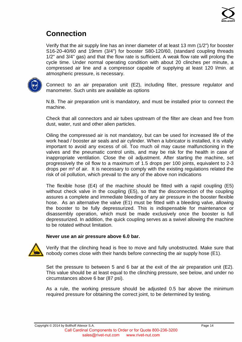
Connection
Verify that the air supply line has an inner diameter of at least 13 mm (1/2”) for booster S16-20-40/60 and 19mm (3/4") for booster S80-120/60, (standard coupling threads 1/2" and 3/4" gas) and that the flow rate is sufficient. A weak flow rate will prolong the cycle time. Under normal operating condition with about 20 clinches per minute, a compressed air line and a compressor capable of supplying at least 120 l/min. at atmospheric pressure, is necessary.
Connect to an air preparation unit (E2), including filter, pressure regulator and manometer. Such units are available as options
N.B. The air preparation unit is mandatory, and must be installed prior to connect the machine.
Check that all connectors and air tubes upstream of the filter are clean and free from dust, water, rust and other alien particles.
Oiling the compressed air is not mandatory, but can be used for increased life of the work head / booster air seals and air cylinder. When a lubricator is installed, it is vitally important to avoid any excess of oil. Too much oil may cause malfunctioning in the valves and the pneumatic control units, and may be risk for the health in case of inappropriate ventilation. Close the oil adjustment. After starting the machine, set progressively the oil flow to a maximum of 1.5 drops per 100 joints, equivalent to 2-3 drops per m³ of air. It is necessary to comply with the existing regulations related the risk of oil pollution, which prevail to the any of the above non indications
The flexible hose (E4) of the machine should be fitted with a rapid coupling (E5) without check valve in the coupling (E5), so that the disconnection of the coupling assures a complete and immediate bleeding of any air pressure in the booster flexible hose. As an alternative the valve (E1) must be fitted with a bleeding valve, allowing the booster to be fully depressurized. This is indispensable for maintenance or disassembly operation, which must be made exclusively once the booster is full depressurized. In addition, the quick coupling serves as a swivel allowing the machine to be rotated without limitation.
Never use an air pressure above 6.0 bar.
Verify that the clinching head is free to move and fully unobstructed. Make sure that nobody comes close with their hands before connecting the air supply hose (E1).
Set the pressure to between 5 and 6 bar at the exit of the air preparation unit (E2). This value should be at least equal to the clinching pressure, see below, and under no circumstances above 6 bar (87 psi).
As a rule, the working pressure should be adjusted 0.5 bar above the minimum required pressure for obtaining the correct joint, to be determined by testing.
Call Cardinal Components to Order or for Quote 800-236-3200 [email protected] www.rivet-nut.com

Copyright © 2014 by Bollhoff Attexor S.A. Page 15
Start-up
Settings for start-up of the clinching system
Check if your machine has been pre-set in the factory for your particular application. (See complement to user’s manual, if any)
In case the machine has not been adjusted from the factory, (or the setting has been lost), remove the tooling (die and punch, see chapter "Replacing wear parts") and check the reference value H as per the next chapter, “Tooling selection and joint optimization, setting the reference value”. H must be from factory set at H=29.0 mm. If not, refer to next chapter for re-setting the H value.
Select the tool corresponding to the sheet metal to be tested from the tables from chapter, “Tooling selection and joint optimization.
Warning: the start-up should not be done if the H value or the tool kit is not set according to the above instruction. In such a case, proceed with chapter "Tooling selection and joint optimization".
Take a sample composed of two flat sheets, hold it against the die side and keep hands off the clinching zone. Make sure that the sample is held flat against the die and perpendicularly to the punch axis.
Press the trigger without releasing until the total cycle has been completed. Wait for the pressure to reach the selected pressure by watching the manometer on the regulator (E2). Then release the trigger. Wait for the punch to be retracted before taking the test piece out.
If the pressure rises very slowly making the cycle too long, > 1 s, the air supply lines and connectors should be checked.
Check the joint. Measure the “ST” value. If needed to be modified, proceed according to the next chapter “Tooling selection and joint optimization” and re-do the test until the correct value of “ST” is obtained.
Test the strength of the joint using a pair of jaws (never attempt to separate clinched sheet metal with naked hands).
In order to avoid excessive tool wear, the following precautions should be respected:
• Do not remove the sheets from the die, pulling laterally as that may damagethe moving parts
• Do not attempt clinching on surfaces that are not flat or where clinching hasalready been made
Call Cardinal Components to Order or for Quote 800-236-3200 [email protected] www.rivet-nut.com

Copyright © 2014 by Bollhoff Attexor S.A. Page 16
• Do not tilt the sheets when the punch has penetrated. Should the sheets getstuck, depressurize the machine. Then liberate the sheet by pulling in theaxial direction of the punch.
• Do not tilt the work head for disengaging the tooling. Always make sure thatthe die blades are never forced
• Never try to assemble sheets of other material or thickness thanrecommended in the tables from chapter, “Tooling selection and jointoptimization
Read carefully the WARNINGS at the beginning of the manual, prior to any operation or testing.
Using of the clinching machine
The procedure to make a clinching point is the following:
• Put together sheets of metal.
• Approach the machine in order to have flanges between the punch and the die.
• Put the fixed tool in contact with the flange.
• Be careful that the tooling is perpendicular with the sheet & that there is nothingbetween layers, particularly operator's fingers.
• Press the clinching trigger (B1) without releasing until the total cycle has beencompleted.
• When the cycle is finished, release the trigger.
When there are several clinching points on the same flange, be careful that there is enough distance between points in order not to touch other points during the clinching cycle.
Call Cardinal Components to Order or for Quote 800-236-3200 [email protected] www.rivet-nut.com

Copyright © 2014 by Bollhoff Attexor S.A. Page 17
Care and Maintenance
Daily maintenance
• Check the air filter(E2). Bleed and clean regularly the water separator.
• Clean punch (A3), die and anvil (A5) with compressed air.
• Check the tooling: the die blades must be hold in contact to the anvil by thespring. The punch top must be free from cracks or chipping.
• Re-oil the tooling after cleaning.
Always use protective glasses when cleaning with compressed air.
Weekly maintenance
This intervention should be made weekly or every 50 service hours, in case of multi-shift operation.
Ref. Fig. 2
• Clean and oil the punch head, without removing the punch.
• Clean the die-anvil (A5) with compressed air and re-oil.
• Check that there are no leaks in the air connections. A leak in the logiccircuitry may disturb the correct working of the machine.
• Ensure that no mobile part rubs against pneumatic or hydraulic tubes andthat the latter are well in place.
• Grease the jaw axis, using a pressure greaser, at grease nipple (A24)
Call Cardinal Components to Order or for Quote 800-236-3200 [email protected] www.rivet-nut.com

Copyright © 2014 by Bollhoff Attexor S.A. Page 18
• Clean the air silencers with compressed air. Always disassemble the bothsilencers and clean it from the inside not the outside. Check the picturesbelow
Always use protective glasses when cleaning with compressed air.
Every 500'000 cycles
The cleaning and re-greasing of the needle bearings is recommended every 500’000 cycles. For more informations ask the technical note Nb 080714.
Call Cardinal Components to Order or for Quote 800-236-3200 [email protected] www.rivet-nut.com

Copyright © 2014 by Bollhoff Attexor S.A. Page 19
Replacing wear parts
Replacing the die-anvil set
Ref. Fig. 3
• Release the pressure from the system by disconnecting the inlet air hose(E1) and by activating the clinching action to make sure that the pressurehas fallen.
• Open completely the moving jaw.
• Remove the pin (A17) using the pin remover (A22) and a small hammer.
• Pull out the anvil (A5). N.B. if the punch is still in place, it may be necessaryto remove the stripper first, as described on the section "replacing the punch-stripper set".
• A new die and anvil is installed by following the above steps in the reverseorder, observing the right orientation of the recess on the die set in case of arectangular tooling is used.
• Make sure that the anvil and the moving parts are clean and free from dirtand that the new die has exactly the parameters required for the intendedtask.
• Install a new die, press it down fully to put it in place
• Re-install the pin (A17) by placing it on the special recess on the tip of thepin remover (A22). Push it with a small hammer without forcing, until the pinis fully in place.
Do not force the die or push it sideways during the disassembly
Control the tightening torque of the elongator (M4 screw = 2.9Nm)
Die ST assembly
Ref. Fig. 3a
In case of replacing the die blades, check the orientation of the blades according to Fig. 3a . A wrong positioning (upside down) may significantly affect the point quality and the lifetime of the die.
Call Cardinal Components to Order or for Quote 800-236-3200 [email protected] www.rivet-nut.com

Copyright © 2014 by Bollhoff Attexor S.A. Page 20
Replacing the punch-stripper set
Ref. Fig. 4
• Release the pressure from the system by disconnecting the inlet air hose(E1) and by activating the clinching action to make sure that the pressurehas fallen
• Remove the locking pin (A17) of the punch
• Pull out the punch (A3) axially, refraining from lateral forcing
• Install a new punch, press it down fully in place
• Re-install the pin (A17) by placing it on the special recess on the tip of thepin remover (A22). Push it with a small hammer without forcing, until the pinis fully in place.
• Re-install the stripper, noting the following:
• The round punch stripper needs a separate back plate,• The rectangular punch stripper must not be installed with a back
plate• The rectangular punch stripper must be oriented properly, with the
flat side outward.
Do not force the punch or push it sideways during the disassembly.
Control the tightening torque of the elongator (M4 screw = 2.9Nm)
Always check upon reassembly that punch and die types correspond exactly to the tool kit selected for the application.
Call Cardinal Components to Order or for Quote 800-236-3200 [email protected] www.rivet-nut.com

Copyright © 2014 by Bollhoff Attexor S.A. Page 21
Tooling selection and joint optimization
Selecting the tooling type
Two types of tooling are currently available, round, nominal diameter 4 mm, SR 403, and rectangular, nominal die width 3.3 mm, ST 332 or width 3.1 mm, ST 312. Other special executions are available on request to your Distributor
The choice is governed by several parameters, in particular:
• MaterialThe type SR is well suited for mild steel, while ST should be preferred for high
strength steel as well as austenitic stainless steel.
• Joint strengthThe type SR offers higher strength for a total material thickness up to 2 mm,
while ST gives stronger joints in thicker material.
• Surface coatingThe type SR leaves a galvanic coating or a good quality paint without damage. On theother hand, thick intermediate layers, powder, plastic foil or a PVC coating, change thestrength of the joint. The type ST is much less sensitive to coatings and fits thereforeapplications with thick layers like plastic film, rubber or filter material.
• Leak proof requirementsA correctly made joint using an SR tool is 100% leak proof. The type ST may be leakproof due to the metallic contact. To achieve this, it is generally enough to select a Jmvalue which is equal to or smaller than the material thickness on the die side.A leak proof ST tooling is available on request, notables for the cases of 3 layers,such as with ventilation clinching. Ask your distributor for more detail.
• GeometryFor the tool dimensions, ref. tables from chapter “Tooling selection and jointoptimization". The type ST 332 is intended for operating close to an edge. On the
Joint type SR
Joint type ST
Call Cardinal Components to Order or for Quote 800-236-3200 [email protected] www.rivet-nut.com

Copyright © 2014 by Bollhoff Attexor S.A. Page 22
other hand, the type SR 403 is more compact laterally which offers an advantage when working in a corner.
• Multi-layerWith mild steel, such as ST14, a tool type SR might be capable of joining three layers.Tests are indispensable. However it is preferable to use the type ST, which handlesmultiple layers in most materials that lend themselves to clinching.
• Uneven thicknessGenerally speaking the type SR may handle a thickness ratio of down to 1:2 betweenthe punch side and the die side thickness. Tests are necessary. However, the type STshould be preferred, especially if the difference is greater, but always subject toverification through testing. It should be remembered that the thicker material on thepunch side is always to be preferred and that punch and die may be inverted to meetthis recommendation.
• Corrosion requirementsThe type SR preserves the galvanic protection, as does, to some extent, the type ST.
Choice of stripper
The stripper is vitally important. It has three functions:
∗ To keep the sheets flat
∗ To participate in the clinching process. Removing the stripper may alter the jointstrength radically
∗ To extract the punch at the end of the clinching process
• Normal working conditions.Use the standard stripper, delivered with the tool kit. Monitor how it wears and changeas required
• Thin or soft sheets.For a total thickness below 1.0 mm it may be necessary to reduce the height of thestripper by careful grinding so as to obtain a flat surface around the joint
• Thick sheets or high strength steel qualities.Special, reinforced or rectangular strippers may be required to maintain a flat surfaceor to facilitate the extraction of the punch in case of high friction
The tables from chapter “Tooling selection and joint optimization" only give indicative values that facilitate the first choice of parameters. Tests on samples are necessary and so are tests on the real products. The following chapter deals with criteria for judging the quality of the joints produced. It may be necessary to carry out tests with other tools or opting for other ST values than those indicated in the tables.
Call Cardinal Components to Order or for Quote 800-236-3200 [email protected] www.rivet-nut.com
Copyright © 2014 by Bollhoff Attexor S.A. Page 23
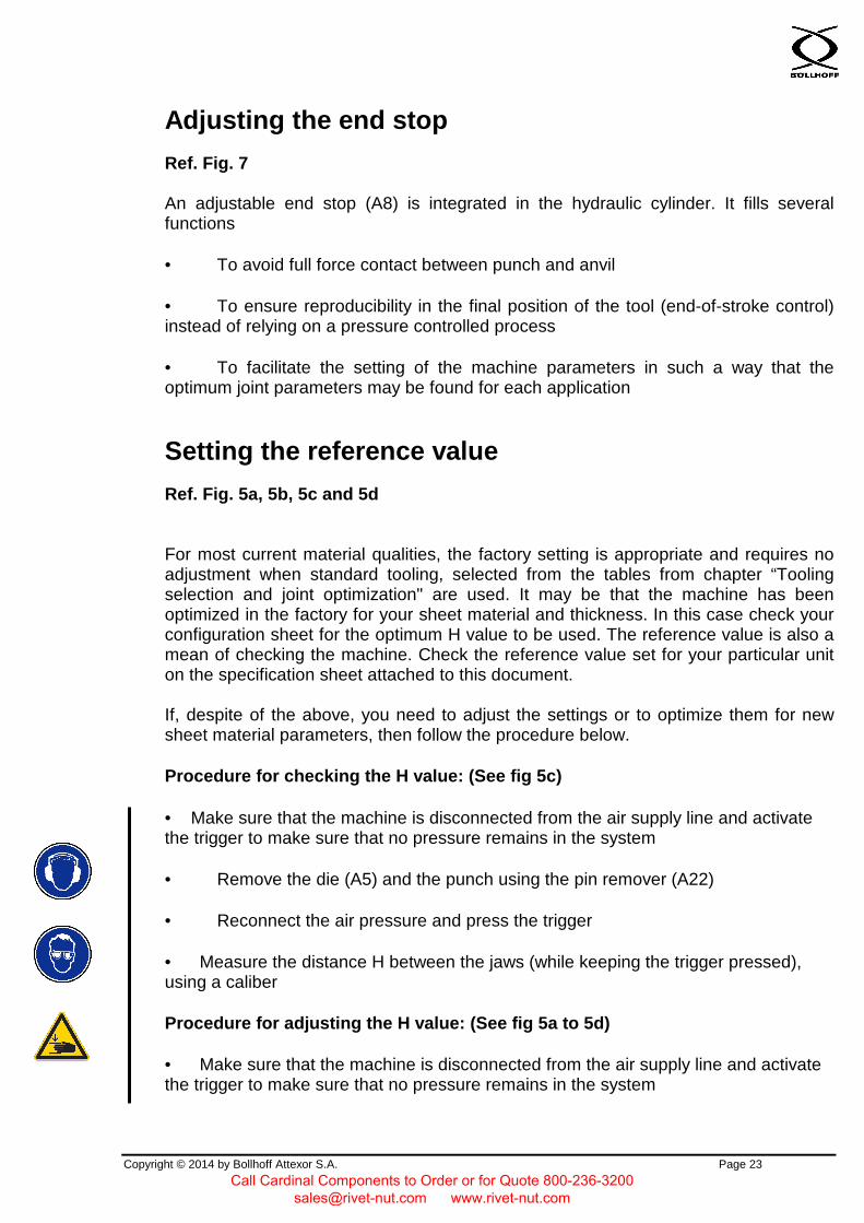
Adjusting the end stop
Ref. Fig. 7
An adjustable end stop (A8) is integrated in the hydraulic cylinder. It fills several functions
• To avoid full force contact between punch and anvil
• To ensure reproducibility in the final position of the tool (end-of-stroke control)instead of relying on a pressure controlled process
• To facilitate the setting of the machine parameters in such a way that theoptimum joint parameters may be found for each application
Setting the reference value
Ref. Fig. 5a, 5b, 5c and 5d
For most current material qualities, the factory setting is appropriate and requires no adjustment when standard tooling, selected from the tables from chapter “Tooling selection and joint optimization" are used. It may be that the machine has been optimized in the factory for your sheet material and thickness. In this case check your configuration sheet for the optimum H value to be used. The reference value is also a mean of checking the machine. Check the reference value set for your particular unit on the specification sheet attached to this document.
If, despite of the above, you need to adjust the settings or to optimize them for new sheet material parameters, then follow the procedure below.
Procedure for checking the H value: (See fig 5c)
• Make sure that the machine is disconnected from the air supply line and activatethe trigger to make sure that no pressure remains in the system
• Remove the die (A5) and the punch using the pin remover (A22)
• Reconnect the air pressure and press the trigger
• Measure the distance H between the jaws (while keeping the trigger pressed),using a caliber
Procedure for adjusting the H value: (See fig 5a to 5d)
• Make sure that the machine is disconnected from the air supply line and activatethe trigger to make sure that no pressure remains in the system
Call Cardinal Components to Order or for Quote 800-236-3200 [email protected] www.rivet-nut.com

Copyright © 2014 by Bollhoff Attexor S.A. Page 24
• Close manually the mobile jaw (A1)
• Unscrew the screw (A9) which retains the eccentric.
• Turn the wheel (A8) to the desired value
• To increase the H value, turn clockwise.
• Re-tight the screw (A9)
It should be observed that this H value is valid when the work head works without sheet material. When material to be clinched is present, the elasticity of the machine will result in a higher residual bottom thickness, the ST value, on the joint than the theoretical one
Finding the optimum setting
The adjustment of the H value may be sufficient for producing an acceptable joint, with a ST value close to the value given in tables from chapter “Tooling selection and joint optimization".
In case the required ST value is not obtained, the end stop must be adjusted, and a final adjustment will be made by testing on a sample and measuring the ST value, ref. to Fig .5a, 5b
• Install the selected tool kit
• Set the drive pressure to 6 bar
• Insert material to be clinched and make a joint, while checking that the air pressure is well stabilized at 6 bar before releasing the trigger
• Measure the ST value using a pivoting caliper gauge or other appropriate device
• Adjust, if necessary the end stop (A8) as described in the above section “Setting the reference value” until the desired ST value is produced on the joint
• To get a greater ST value, turn clockwise
• To reduce the ST value, turn anti-clockwise
• Repeat the process until the desired ST value is obtained
The tables from chapter “Tooling selection and joint optimization" only give indicative values that facilitate the first choice of parameters. Tests on samples are necessary
Call Cardinal Components to Order or for Quote 800-236-3200 [email protected] www.rivet-nut.com

Copyright © 2014 by Bollhoff Attexor S.A. Page 25
and so are tests on the real products. It may be necessary to carry out tests with other tools or opting for other ST values than those indicated in the tables.
Quality control
Ref. Tables chapter “Tooling selection and joint optimization".
It is common practice for production control to check the ST value at regular interval during the production process. This is a simple, non-destructive quality control operation and a deviating ST value will signal malfunction of the machine or the tool kit, changes in the sheet material, non-appropriate handling by the operator or shortcomings in the air supply.
Alternatively or as a complement to ST value, the diameter D1 of the button (or W1 for a rectangular point) can be a good quality control value, despite it is less accurate than ST. in case of using this measurement (D1 or W1) it is necessary to determine the reference value specific to the application and note it down in this manual.
Samples can be produced at regular intervals, make a cut on the joint and check by a microscope that the button locking and neck are unchanged compared to the reference sample
The tooling (punch and die) must be checked at regular intervals. Criteria for tool changes are:
Visible cracks or chipped zone on the punch tip, on the die parts, on the anvil
• Punch diameter loss exceeding 0.1mm
• Die spring damaged (can be replaced)
• Die cage damaged or deformed in such a way that the die blades do not moveproperly
Call Cardinal Components to Order or for Quote 800-236-3200 [email protected] www.rivet-nut.com
Copyright © 2014 by Bollhoff Attexor S.A. Page 26
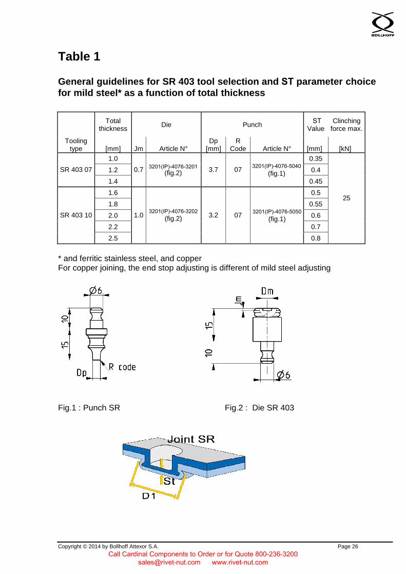
Table 1
General guidelines for SR 403 tool selection and ST parameter choice for mild steel* as a function of total thickness
Total thickness
Die Punch ST Value
Clinching force max.
Tooling type [mm] Jm Article N°
Dp [mm]
R Code Article N° [mm] [kN]
1.0 0.35
1.2 0.4 SR 403 07
1.4
0.7 3201(IP)-4076-3201 (fig.2) 3.7 07
3201(IP)-4076-5040 (fig.1)
0.45
1.6 0.5
1.8 0.55
2.0 0.6
2.2 0.7
SR 403 10
2.5
1.0 3201(IP)-4076-3202
(fig.2) 3.2 07 3201(IP)-4076-5050
(fig.1)
0.8
25
* and ferritic stainless steel, and copperFor copper joining, the end stop adjusting is different of mild steel adjusting
Fig.1 : Punch SR Fig.2 : Die SR 403
Call Cardinal Components to Order or for Quote 800-236-3200 [email protected] www.rivet-nut.com

Copyright © 2014 by Bollhoff Attexor S.A. Page 27
Table 2
General guidelines for ST 332 tool selection and ST parameter choice for mild steel as a function of total thickness
Total thickness
Die Punch ST Value
Clinching force max.
Tooling type [mm] Jm Article N°
Wp x Tp [mm] Code Article N° [mm] [kN]
1.0 0.5 ST 332 07
1.2 0.7 3201(IP)-4076-7011
(fig.2) 0.6 1.4 0.7 1.6 0.8 ST 332 09 1.8
0.9 3201(IP)-4076-7018 (fig.2)
0.9 2.0 1.0 2.2 1.1 ST 332 12 2.5
1.2 3201(IP)-4076-7010 (fig.2)
3.0x3.0 03
3201(IP)-4076-7110 (fig.1 for
elastomer stripper)
1.3
25
* and ferritic stainless steel, and copperFor copper joining, the end stop adjusting is different of mild steel adjusting
Fig.1: Punch ST 30x30 Fig.2: Die ST 332
Call Cardinal Components to Order or for Quote 800-236-3200 [email protected] www.rivet-nut.com

Copyright © 2014 by Bollhoff Attexor S.A. Page 28
Table 3
General guidelines for ST 312 tool selection and ST parameter choice for stainless steel as a function of total thickness
Total thickness Die Punch
ST Value
Clinching force max.
Tooling type [mm] Jm Article N° Wp x Tp
[mm] Code Article N° [mm] [kN]
ST 312 07 1.0 0.7 3201(IP)-4076-7017 (fig.2) 0.7
ST 312 08 1.2 0.8 3201(IP)-4076-7013 (fig.2) 0.8
1.4 0.9 ST 312 10 1.6
1.0 3201(IP)-4076-7012 (fig.2) 1.0
ST 312 12 1.8 1.2 3201(IP)-4076-7014
(fig.2)
3.0x3.0 03 3201(IP)-4076-7111 (fig.1 for elastomer
stripper)
1.2
25
* Punch with special coatin Z1
Fig.1: Punch ST 30x30
Fig.1: Punch ST 30x30 Fig.2: Die ST 312
Call Cardinal Components to Order or for Quote 800-236-3200 [email protected] www.rivet-nut.com

Copyright © 2014 by Bollhoff Attexor S.A. Page 29
Figures
Call Cardinal Components to Order or for Quote 800-236-3200 [email protected] www.rivet-nut.com

Copyright © 2014 by Bollhoff Attexor S.A. Page 30
Fig. 1. Main dimensions
RC 3201(IP)
Call Cardinal Components to Order or for Quote 800-236-3200 [email protected] www.rivet-nut.com

Copyright © 2014 by Bollhoff Attexor S.A. Page 31
RC 3201(IP) V2
Call Cardinal Components to Order or for Quote 800-236-3200 [email protected] www.rivet-nut.com

Copyright © 2014 by Bollhoff Attexor S.A. Page 32
Fig. 2. Various components and functions
A5
D1
A1
A2
A3, A4
A24
B2
B1
A62
A61
Call Cardinal Components to Order or for Quote 800-236-3200 [email protected] www.rivet-nut.com

Copyright © 2014 by Bollhoff Attexor S.A. Page 33
Fig. 2b, Installation of hand operated tool
E2 E1
E4
D4
D1
D6
D5
B1
Call Cardinal Components to Order or for Quote 800-236-3200 [email protected] www.rivet-nut.com

Copyright © 2014 by Bollhoff Attexor S.A. Page 34
Ref. Figs. 2. RIVCLINCH ® 3201(IP)
A. WorkheadA1 Moving jaw A2 Fixed jaw A3 Punch A4 Stripper A5 Die with anvil (could be inverted with punch) A8 End stop wheel A9 Looking screw A17 Fixing pin A22 Pin remover A23 Stripper back-up washer A24 Greasing nipples A40 Die spring A42 Die blade set A43 Die balde screw A44 Die holder (elongator and protection) A45 Anvil A46 Die tail with semi-round notch A47 Punch holder (elongator) A60 Needle bearing A61 Pivoting shaft A62 Forward inferior shaft A63 Rearward inferior shaft
B. HandleB1 Trigger B2 Pneumatic connection
D. SuspensionD1 Suspension ring D2 Rotating suspension (rotator) D4 Balancer D5 Pivoting frame D6 Linear moving frame
E. SupplyE1 Inlet air hose with valve with fast purging E2 Pressure regulator and filter / water separator E4 Air feeding hose for the booster
Call Cardinal Components to Order or for Quote 800-236-3200 [email protected] www.rivet-nut.com

Copyright © 2014 by Bollhoff Attexor S.A. Page 35
Fig. 3. Removing the die-anvil set
A5
A22
A17
Call Cardinal Components to Order or for Quote 800-236-3200 [email protected] www.rivet-nut.com

Copyright © 2014 by Bollhoff Attexor S.A. Page 36
Fig. 3a. Right orientation of the recess on the die set
Fig. 4 Removing the punch-stripper set
A4
A3
A22
A17 A1 / A2
A42
Call Cardinal Components to Order or for Quote 800-236-3200 [email protected] www.rivet-nut.com

Copyright © 2014 by Bollhoff Attexor S.A. Page 37
Fig. 5. Adjusting the end-of-stroke, H and ST values
Fig.5a
Fig.5c
Fig.5d
ST
H, ST
+ -
Fig.5b
A8
A9
Call Cardinal Components to Order or for Quote 800-236-3200 [email protected] www.rivet-nut.com