r.becker (mit) 15/10/02 ugbs main plate patrick schmid (left) of ethz did the cnc machining of the...
TRANSCRIPT

R.Becker (MIT) 15/10/02
UGBS Main Plate
Patrick Schmid (left) of ETHZ did the CNC machining of the plate.
Urs Horisberger (ETHZ) Completed follow up machining

R.Becker (MIT) 15/10/02
UGBS Plate Machining
• Back (top) & Front (right) sides of plate
R.Becker (MIT) 15/10/02
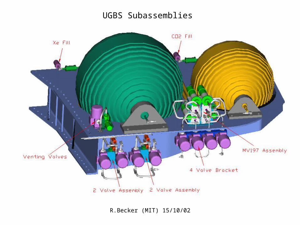
UGBS Subassemblies
R.Becker (MIT) 15/10/02
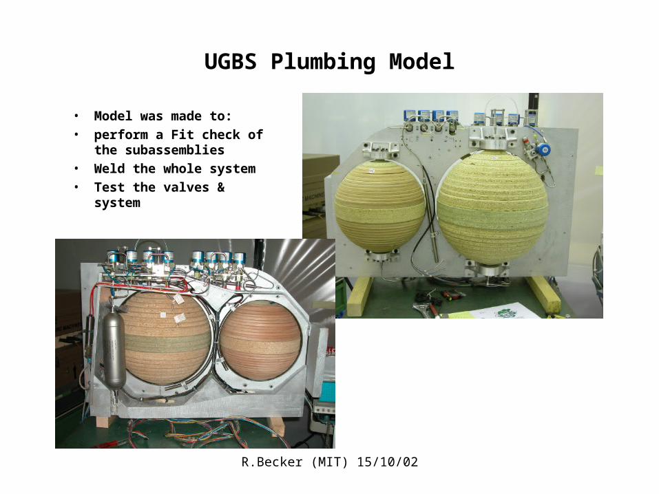
UGBS Plumbing Model
• Model was made to:
• perform a Fit check of the subassemblies
• Weld the whole system
• Test the valves & system
R.Becker (MIT) 15/10/02
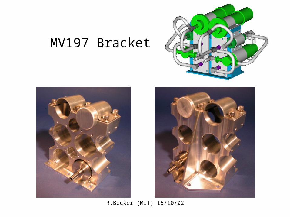
MV197 Bracket

R.Becker (MIT) 15/10/02
MV197 Bracket Tube welding
• The full assembly looks like this • Easier to look at half! The welding procedure will look at only half since the other side is mirror symmetrical

R.Becker (MIT) 15/10/02
2 Step Construction
• First the “U” (welding steps 1,2,3) are welded not mounted in the bracket.
• Then the xv254 and the filter are mounted and welded (steps 4-6)
• The GP50 is installed and all remaining welds performed.
• The welded components are now removed to allow for the welding of the MV197 valves
• The MV197’s are installed and secured as shown
• The “U” (steps 1,2) is pre-welded and then welded to the valves (steps 3,4)
• the 1/4”-1/8” reducers are pre-welded to the T-junctions and then welded to the valves (steps 7,8)
• The “U’ is then welded (steps 9,10)
• The “U” to the xv234is then welded per step 11.
Step 1 Step 2

R.Becker (MIT) 15/10/02
Step 3
• The Step 1 components are then mounted and welded (It may be more practical that all 4 mv197 are mounted before installing the pre-welded pressure and filter units)
• Perform same steps for mirror side
• Note also, all 1/8” tubes going to the buffer volumes or otherwise (NOT SHOWN -but at the ends of all 1/4-18” reduction pieces) need to be pre-welded -the welding head will not fit later.

R.Becker (MIT) 15/10/02
4 Valve Bracket Welding Sequence
• Follow sequence as shown
• Welds 1 & 5 need attention since they may need to be done first

R.Becker (MIT) 15/10/02
4 Valve Bracket

R.Becker (MIT) 15/10/02
2 Valve Bracket

R.Becker (MIT) 15/10/02
2Valve Bracket Welding Sequence
• Welding follows the sequence above.
• Step (12)* is welded after inserting the filter into the bracket.
• Weld 4 in the 2nd step should be performed after the oriface/filter unit is loosely fitted into the bracket
• After welding is copleted RTV is injected in the Filter cavity
Step 1 (Oriface/Filter Unit)
Step 2 (valves)
2 valve bracket Completed
R.Becker (MIT) 15/10/02
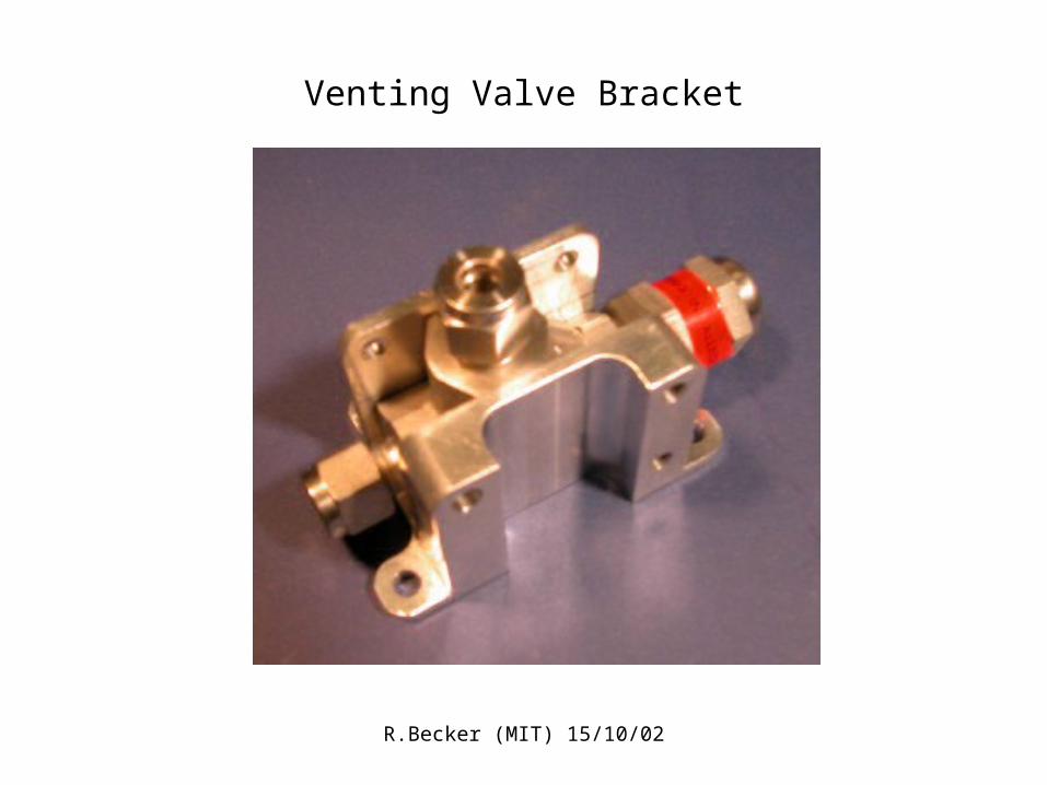
Venting Valve Bracket

R.Becker (MIT) 15/10/02
TRD Gas System Mechanics StatusR.Becker (MIT) October 30, 2002
Radiator not shown
• UGBS design done, commercial version being assembled
• Flight main plate ordered, & most flight brackets manufactured
• UGBS kit including welding procedures being prepared for ARDE
• UGBC design needs to be finalized
• UGBC to TRD manifold plumbing & bracketry designs needed
R.Becker (MIT) 15/10/02
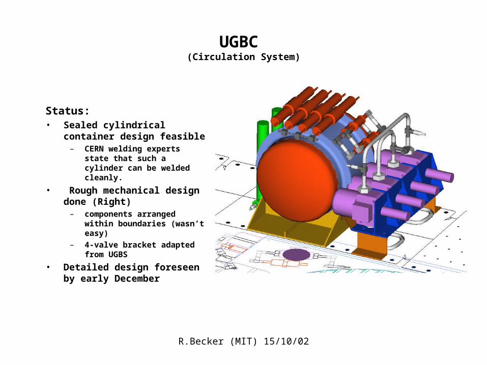
UGBC (Circulation System)
Status:• Sealed cylindrical container design
feasible– CERN welding experts state that
such a cylinder can be welded cleanly.
• Rough mechanical design done (Right)
– components arranged within boundaries (wasn’t easy)
– 4-valve bracket adapted from UGBS
• Detailed design foreseen by early December