rathi transpower pvt. ltd. pune - india
TRANSCRIPT

Technical Manual: Drive Shaft Coupling-01/03-08/14
RATHI TRANSPOWER PVT. LTD. PUNE - INDIA
TECHNICAL MANUAL
DRIVE SHAFT COUPLING

Technical Manual: Drive Shaft Coupling-01/03-08/14
INDEX
CONTENTS PAGE • Rathi Catalog 1-2
• Technical Data Sheet-Rathi Drive Shaft 3
• Rathi Drive Shafts-Part & Assembly Description 4
• GA Drawings: Type RDT 5-13
• GA Drawings: Type RDS 14-29
• Application Data Sheet 30
• Applications of Drive Shafts 31
• Coupling Selection Program for Drive Shafts 32
• Painting, Marking, Packing 33
• Dynamic Balancing 33
• Polyamide Coating 33
• Length Construction of Drive Shafts 34
• Bearing Life 34
• Weight 34
• Material of Construction 34
• Failure Modes & Diagnosis 35-37
• Installation Instructions 38-40
• Lubrication of Drive Shafts 41
• Trouble Shooting Guide 42
• Safety Precautions 43
• Maintenance Instructions 44
• Warranty Statement 44


*

SrNo
DriveShaftSeries
ShortDurationTorque
Nm
Flange Dia. ØA
Spigot Dia.ØE Spigot Height
FFlange THK.
T ±0.5
No of Flange Holes
N
Bolt HoleDia.
Ød (+0.2, 0)
Flange PCDP
AngleBº, max.
Slip Movement
K
LengthFCL-FEL
Slip Movement
K
LengthFCL-FEL
23.8 208-232
41 258-29925 250-275
49.2 281-330
30 250-28040 264-30430 300-330
4 1480 ■ 2712 Rect. Flange 1.80 10.30 4 12.85 120.75/120.60 20 63.5 418-481 50 270-320
25 248-273
33 308-341
40 340-380
45 377-422
7 1710 6511 203.2 + 0.050
0196.77
2.00 7.60 8 10.50 184.10/184.22 20 133 638-771 98 485-583
98 480-578
104 618-722
NOTES:
1) All dimensions in mm unless specified.
2) ■ Rectangle flange.
3) Drive shaft balanced to Gr. G-16 as per ISO 1940 at 1500 rpm.
4) Fully compressed length of drive shafts to be specified by customer.
* MODEL-RDT:- Rathi Drive Shaft Assembly (Tube), Veriable length can be supplied as per order.
* MODEL-RDS:- Rathi Drive Shaft Short Coupled, fixed length.
63.5 445-508
500-57070
5 1550 ■ 3255 Rect. Flange
10.50 155.60/155.45 20
+ 0.050 095.2 1.60 10.30 4 20
+0.050 0168.2
1.59 8.00 86 1610 4950 174.6
CUSTOMER :PREPARED BY:SPKAPPROVED BY: AGK
8 1720 6511 150
RATHI TRANSPOWER PVT LTDPUNE (INDIA)-411006
±0.1146
4 12.50 95.35/95.20
120.75/120.6012.75
3 1410 ■ 2034 +0.050
069.8
4
2 1310 ■ 1085 +0.050
060.27
1.52 7.10 4
550
3 11.00
DATE: 08/07/14 Date : 03/11/12
133 650-783
REF. NO. : DOC. NO.DMRN: A261 T/D- 301A/4
8.20 69.95/69.80 17
10.50 79.45/79.30 25
TECHNICAL DATA SHEET- DRIVE SHAFTS ( NEW PLAN )
8-HOLE FLANGE
MODEL 1720 FLANGE
471-529
335-385
315-358
* MODEL - RDT * MODEL - RDS
1 1130
4 13.00 130.00/130.2 15
20 58
50.8
42.8
4-HOLE RECT. FLANGE 4-HOLE FLANGE
Rect. Flange
Rect. Flange
5.20
1.50 7.25
+0.050 057.1
2.6087.3

FLANGE YOKE UJ KIT STUB YOKE TUBE SLIP SHAFT
SLEEVE YOKE
UJ KIT FLANGE YOKE
FLANGE YOKE UJ KIT YOKE SHAFT SLEEVE YOKE UJ KIT FLANGE YOKE
PARTS
UJ KIT STUB YOKE
SLIP SHAFT SLEEVE YOKE UJ KIT FLANGE YOKE
DOC. NO.T/D-301B/0Date :19/10/12
PARTS
SLIP JOINT ASSEMBLY, TYPE-RSJ
RATHI TRANSPOWER PVT LTDPUNE (INDIA) APPROVED BY:AGK
CUSTOMER : REF. NO. :PREPARED BY:SPK DMRN :
DATE :
A. FIXED JOINT PARTS & ASSEMBLY
FIXED JOINT ASSEMBLY, TYPE-RFJ
FLANGE YOKE
B. SLIP JOINT PARTS & ASSEMBLY
RATHI DRIVE SHAFTS- PART & ASSEMBLY DESCRIPTION
RATHI DRIVE SHAFT ASSEMBLY (TUBE), TYPE-RDT
PART DESCRIPTION
ASSEMBLY
RATHI DRIVE SHAFT SHORT COUPLED, TYPE-RDS
PART DESCRIPTION
ASSEMBLY

Page 5
RATHI DRIVE SHAFT ASSEMBLY (TUBE), TYPE-RDT
Sr. No. Drive Shaft Series
Short Duration
Torque Nm
Slip Movement FCL-FEL RTPL'S
Drg. No.
1 1130 550 42.8 315-358 SKT-1618
2 1310 ■ 1085 50.8 335-385 SKT-1619
3 1410 ■ 2034 58 471-529 SKT-1620
4 1480 ■ 2712 63.5 418-481 SKT-1621
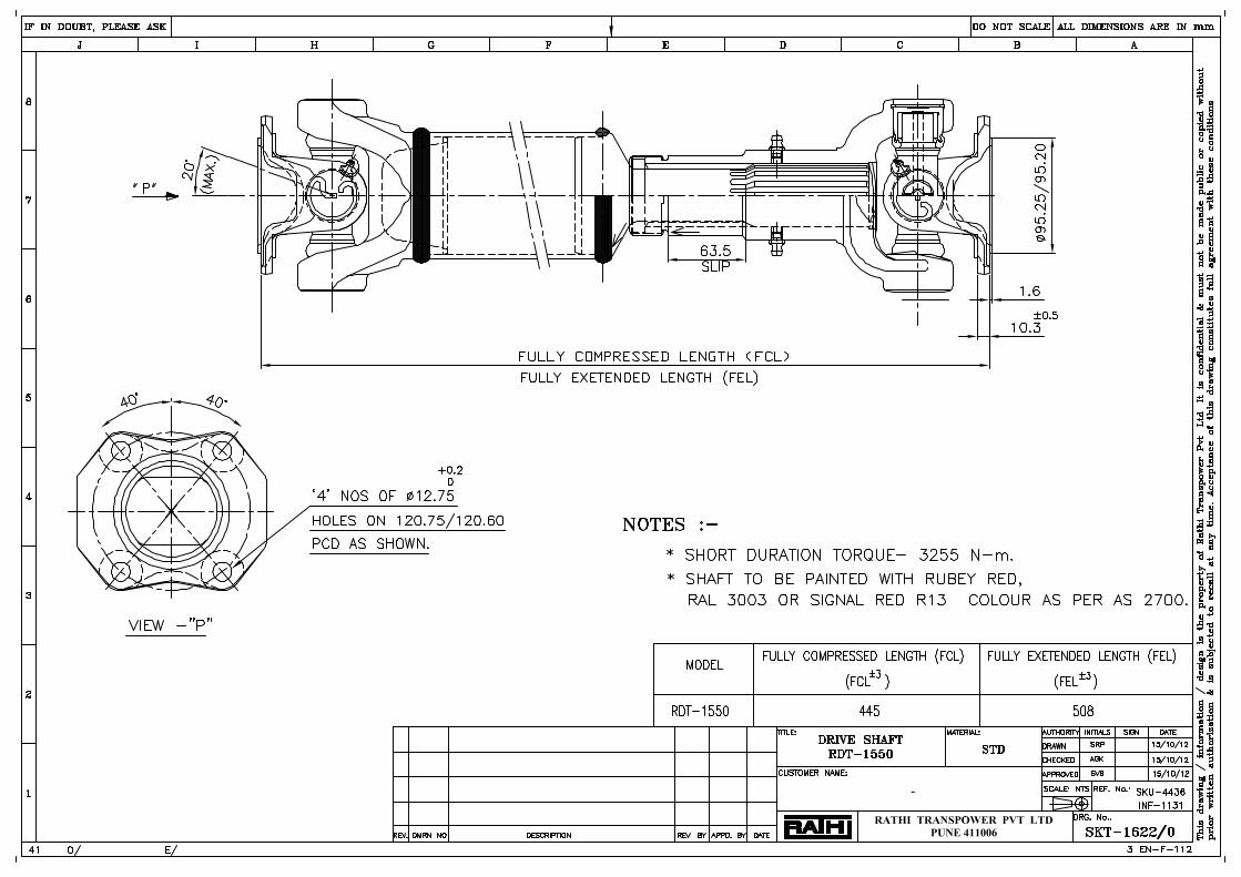
5 1550 ■ 3255 63.5 445-508 SKT-1622
6 1610 4950 70 500-570 SKT-1623
7 1710 6511 133 638-771 SKT-1838
8 1720 6511 133 650-783 SKT-1746


Page 14
RATHI DRIVE SHAFT SHORT COUPLED, TYPE-RDS
Sr. No. Drive Shaft Series
Short Duration Torque
Nm
Slip Movement FCL-FEL RTPL'S Drg.
No.
23.8 208-232 SKT-1625 1 1130 550
41 258-299 SKT-1738
25 250-280 SKT-1739 2 1310 ■ 1085
49.2 281-330 SKT-1625
30 250-280 SKT-1740
40 264-304 SKT-1741 3 1410 ■ 2034
30 300-330 SKT-1627
4 1480 ■ 2712 50 270-320 SKT-1628
25 248-273 SKT-1742 5 1550 ■ 3255
33 308-341 SKT-1629
40 340-380 SKT-1743 6 1610 4950
45 377-422 SKT-1630
7 1710 6511 98 485-583 SKT-1837
98 480-578 SKT-1744 8 1720 6511
104 618-722 SKT-1745


Page 30
Date: Contact Person: Designation:Company: Phone No.:Address: Fax:
Email:website:
A. Specify Horizontal / Vertical Mounting
B OPERATING PARAMETERS 21 Application2 Prime Mover
Type Rating kW/NmOperating speed rpm minOperating speed rpm maxOverload out put mill ( rpm )
3 Gear box reduction ratio4 Operating method ( rev / non - rev )5 Operating Hrs per day6 Max operating angle (Bº)7 Min / Max Roll Diameter mm8 Required LIFE Hrs9 Number of drive shafts required
C MOUNTING OPTIONS EXISTING/NEW 1 Drive Side : a ) SAE Plate
b ) Shaft 2 Driven Side : Shaft 3 Fully Compressed Length (FCL)4 Slip Movement (K)5 Flange Dia (ØA)6 Spigot Dia (ØE)7 Spigot Depth (F)8 Number of holes (N) x Hole dia (Ød)9 PCD (P)D Remark
Please Refer Rathi Drive Shaft Catalogue for standard Length ( FCL & K )3EN-F-113 Rev. 00
RATHI TRANSPOWER PVT. LTD.DRIVE SHAFT APPLICATION DATA SHEET
TECHNICAL DATA TO Filled by Customer 1
APPLICATION DATA SHEET FOR DRIVE SHAFT

Page 31
APPLICATIONS OF DRIVE SHAFT COUPLING
Typical applications of Drive Shaft Couplings are: Steel Plants & Rolling Mills, Textile, Paper & Printing Machinery, Cranes & Fire Fighting Pump drive, Vibrating screens, Cement Industries, Earth Moving Equipments etc.
Refer product catalogue for detail selection procedure for drive shaft couplings Example for selection of drive shaft coupling:- A Drive Shaft Coupling is required to transmit 40HP (29.84 KW) @ 1500 rpm from 6 cylinder Diesel Engine to a centrifugal pump. Engine flywheel SAE size is 10” & pump shaft dia. is 60 mm. The operating angle is 1 to 3º maximum and bearing life is 10,000 hours. DBSE=335 mm. Refer product catalogue for service factors of POWER SOURCE (FP), ANGLE FACTOR (FA) & LIFE FACTOR (FL). a) Service factor for diesel engine, FP = 1.5 Service factor for operating angle, FA = 1 Service factor for bearing life, FL = 1.2 b) Application Toque, T = Power kW x 1.34 x 7123 N-m RPM = 29.84 x 1.34 x 7123 = 190 N-m 1500 c) Calculate Design Torque = T x FP x FA x FL N-m = 190 x 1.5 x 1 x 1.2 = 342 N-m NOTE: For forward & reverse applications use additional multiplying factor of `2’ with above service factors while calculating the design torque. Selected Drive Shaft Coupling size-1310 having short duration torque capacity of 1085 N-m & max bore size 65 mm (JUMBO HUB, RDJ) is OK.
ORDERING EXAMPLE : For above example, specify the coupling size requirement as (also provide Finish bore keyway details & the required tolerance along with):
SAE Plate RDP + Drive Shaft RDT + RDJ SAE Plate RDP-10” + RDT-1310 (335) + RDJ-1310 in FB (FB Size-60)
Page 32
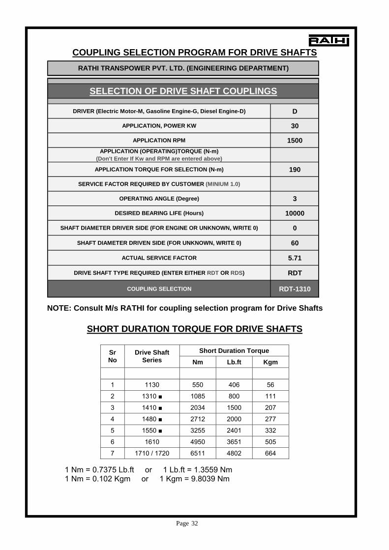
DRIVER (Electric Motor-M, Gasoline Engine-G, Diesel Engine-D) D
APPLICATION, POWER KW 30
APPLICATION RPM 1500APPLICATION (OPERATING)TORQUE (N-m)
(Don't Enter If Kw and RPM are entered above)
APPLICATION TORQUE FOR SELECTION (N-m) 190
SERVICE FACTOR REQUIRED BY CUSTOMER (MINIUM 1.0)
OPERATING ANGLE (Degree) 3
DESIRED BEARING LIFE (Hours) 10000
SHAFT DIAMETER DRIVER SIDE (FOR ENGINE OR UNKNOWN, WRITE 0) 0
SHAFT DIAMETER DRIVEN SIDE (FOR UNKNOWN, WRITE 0) 60
ACTUAL SERVICE FACTOR 5.71
DRIVE SHAFT TYPE REQUIRED (ENTER EITHER RDT OR RDS) RDT
COUPLING SELECTION RDT-1310
RATHI TRANSPOWER PVT. LTD. (ENGINEERING DEPARTMENT)
SELECTION OF DRIVE SHAFT COUPLINGS
COUPLING SELECTION PROGRAM FOR DRIVE SHAFTS
NOTE: Consult M/s RATHI for coupling selection program for Drive Shafts
SHORT DURATION TORQUE FOR DRIVE SHAFTS
Short Duration Torque Sr
No Drive Shaft
Series Nm Lb.ft Kgm
1 1130 550 406 56
2 1310 ■ 1085 800 111
3 1410 ■ 2034 1500 207
4 1480 ■ 2712 2000 277
5 1550 ■ 3255 2401 332
6 1610 4950 3651 505
7 1710 / 1720 6511 4802 664 1 Nm = 0.7375 Lb.ft or 1 Lb.ft = 1.3559 Nm 1 Nm = 0.102 Kgm or 1 Kgm = 9.8039 Nm

Page 33
• PAINT SPECIFICATION:
Ruby red, RAL 3003 or Signal Red R13 as per AS 2700.
• MARKING DETAILS:
ITEM PUNCHING DETAILS Rathi Drive Shaft SAE Plate, (RDP) SAE Plate-Z (Z is Size e.g. 7 1/2", 10")
Drive Shaft RDT/RDS 1. RDT/RDS-XXXX (XXXX is size e.g. 1310, 1480 etc) 2. Y- Fully Compressed Length (As per Purchase Order)
Rathi Drive Shaft Hub, (RDH) / Jumbo Hub, (RDJ)
1. RDT/RDS-XXXX (XXXX is size e.g. 1310, 1480 etc) 2. Y- Fully Compressed Length (As per Purchase Order) 3. Finish Bore Size (eg. Ø35, Ø50, etc.)
*- Refer above figure for punching locations.
• PACKING: The Drive Shaft Assembly will be packed in plastic bag individually.
• DYNAMIC BALANCING: a) Rathi Drive Shaft Short Coupled (RDS) need no dynamic balancing; they fall
within balancing grade G16. b) Rathi Drive Shaft Assembly Tube (RDT) with fully compressed length (FCL)
up to 200 mm, no DB is required. Whereas RDT with FCL above 200 mm are supplied with DB confirming to grade G16.
• POLYAMIDE COATING:
All drive shafts will be supplied with polyamide coating on spline shaft. This improves the wear and tear of the spline and reduces the noise and the backlash.

Page 34
• LENGTH CONSTRUCTION OF DRIVE SHAFTS:
The drive shaft can be supplied upto 1.5 mtr long in one piece construction.
For 1.5 mtr to 2.5 mtr, drive shaft is supplied with two piece construction with one central bearing.
Above 3mtr, drive shaft is supplied with 3 piece construction with two central bearing.
Consult M/s RATHI for design details.
• BEARING LIFE: At 3 degree bearing life is minimum 5000 hrs. As the angle increases the life reduces. While selecting the correct drive shaft customer inputs are very important. Refer graph of Desired Bearing Life (Hours) vs Life Factor shown in the product catalogue for more details.
WEIGHT FOR DRIVE SHAFTS
Wt. in kg Wt. in kg Sr. No.
Drive Shaft Series
RDT FCL-FEL
RDT
RDS FCL-FEL
RDS 208-232 1 1130 315-358 5.01 258-299 250-280 4.54 2 1310 ■ 335-385 5.1 281-330 4.9 250-280 6.87 264-304 3 1410 ■ 471-529 300-330 7.2
4 1480 ■ 418-481 270-320 9.4 248-273 5 1550 ■ 445-508 308-341 11.9 340-380 6 1610 500-570 377-422 17.5
7 1710 638-7715 37.1 485-583 36.2 480-578 30.21 8 1720 650-783 618-722
Note: Data to be updated shortly
MATERIAL OF CONSTRUCTION FOR DRIVE SHAFTS
Note: Data to be updated shortly

Page 35
FAILURE MODES & DIAGNOSIS
• Driveshaft inspection should be performed as part of a regular maintenance routine. Normal maintenance and recognition of component discrepancies is necessary to prevent serious mechanical problems as well as accidents.
• Failure to perform normal maintenance may also void the drive shaft warranty. Routine Inspection Steps: 1. Check the output and input end yokes for looseness. 2. Check for excessive radial looseness of output/input shaft. 3. Check for looseness across ends of u-joint. 4. Check the slip spline for excessive radial movement. 5. Check the shaft for damage, bent tubing or missing balance weights. 6. Check for loose or missing plug. Component failures can result from improper maintenance, installation or assembly procedures. This quick reference guide assists service technicians in recognizing component failures and identifying probable causes. a) Universal Joints: Fractured U-Joint Cross
Probable Causes: • Excessive torque loads • Shock loads • Improper application
b) Universal Joints: Cross-End Galling
Probable Causes: • Excessive u-joint operating angles • Improper assembly procedures • Sprung or bent yoke • Lack of lubrication (improper maintenance)

Page 36
c) Universal Joints: Cross-Spalling Probable Causes: • Water contamination • Improper lube type • Lubrication failure
d) Universal Joints: Cross-Brinelling Probable Causes: • Excessive continuous torque loads • Seized slip yoke splines • Excessive driveline angles • Sprung or bent yoke
e) Tubing: Broken Welds Probable Causes: • Shock loads • Improper welding procedures • Excessive vibration
f) Tubing: Twisting Probable Causes: • Excessive torque • Driving into immovable object under power

Page 37
g) Tube Shafts: Fractured Spline Probable Causes: • Excessive torque loads • Shock loads • Improper application
h) Yokes: Bent Yoke Probable Causes: • Excessive torque • Improper application • Improper u-joint removal
i) Yokes: Fractured Yoke Probable Causes: • Excessive torque loads • Shock loads • Improper application • U-joint kit failure

Page 38
INSTALLATION INSTRUCTIONS
IMPORTANT - Read Carefully These instructions are provided to aid in the proper handling, installation and maintenance of RATHI DRIVE SHAFT COUPLINGS. They should be carefully read and followed. Failure to do so may result in unsatisfactory service as well as serious personal injury or property damage. ASSEMBLY POSITION: Drive end (motor/engine) should be slip joint, driven end (pump) is fixed joint. IF THERE ARE ANY QUESTIONS CONCERNING PROPER INSTALLATION, MAINTENANCE OR STORAGE, CONTACT M/s RATHI BEFORE PROCEEDING.
HANDLING & STORAGE: 1) Examine all drive shafts and related material upon arrival and note any damage or shortage on bill of lading. Such damage is the responsibility of the freight carrier. All transportation and storage should be in a horizontal position only.
2) Shocks, bumps and mishandling must be avoided to assure proper performance. Abuse could result in bending the drive shaft, causing whipping and unbalance problems. Damage of this nature will VOID the warranty.
REPAIR SHOULD ONLY BE DONE BY THOSE WITH EXPERIENCE IN APPLYING, INSTALLING, SERVICING AND REBUILDING INDUSTRIAL UNIVERSAL JOINT TYPE DRIVE SHAFTS. EQUIPMENT ALIGNMENT: 1) The deflection angles (β°1 & β°2) of both joints must also be equal to one another within ±1°. This can be achieved by either Parallel offset or Angular misalignment.
2) The maximum joint operating angle of 3° is recommended for optimum bearing life. While, in theory, shafts should be offset slightly, to initiate bearing rotation, experience indicates that there is sufficient deviation in most applications for essential bearing rotation.
3) The preferred angle is ½° to 1°, unless the driver or driven produces torque spikes, such as a reciprocating engine or compressor, then an operating angle of 2° to 3° is desirable.
a) PARALLEL OFFSET:

Page 39
Driving and driven shaft of your equipment must be parallel to within ±1°. An offset "A" of 1/8" to 3/16" per foot of joint coupling measured joint centre to joint centre distance "B" is equivalent to approximately ½° to 1°. (β°1 = β°2). b) ANGULAR MISALIGNMENT: The driver and driven shaft centrelines, of your equipment, must intersect at the centre of the drive shaft. (β°1 = β°2) The maximum joint operating angles depend upon the shaft series and operating speed, consult M/s RATHI or our master catalogue. INSTALLATION: 1) Check the hub bores and shaft diameters for proper fit. All mating surfaces, bores and faces must be clean and free from grease, oil, dirt, nicks and other contaminates to insure a proper fit and function of mating parts. The shaft should not extend beyond the hub face. 2) Mount the coupling hub on the shaft. One set screw is provided to lock the hub into position. 3) An additional set screw at 90 degree is supplied for vertical installations. In vertical applications where the drive shaft weight exceeds 300 lbs., we recommend an interference fit, split ring key or jam nut to support the weight. 4) For light interference or shrink fits heat the hub uniformly (preferably submerged in oil not exceeding 350° F) to expand the bore. Align the keyways in both the shaft and hub, slide the hub onto shaft and allow to cool. CAUTION: Do not attempt to hammer an undersized hub on without heat. 5) Splined telescoping assemblies should not be disassembled to avoid misalignment and unbalance. Slip shaft and sleeve yoke must be aligned in phase. Check the match markings. 6) For fixed length shafts, one hub must be free to move to allow slight length variation due to temperature changes, etc. 7) To insure long life and trouble free operation, units should be regularly inspected to insure that bolts are tight, mating hubs are secure and lubrication seals and jerk fittings are intact. 8) Any unusual sound or vibration should be located and corrected immediately. WHEREVER PEOPLE OR EQUIPMENT CAN BE ENDANGERED BY ROTATING UNIVERSAL SHAFTS, SAFETY DEVICES MUST BE PROVIDED BY USER!

Page 40
TABLE 1 Bolt Tightening Torques
Drive Shaft Sizes
Bolt Size
Tightening Torque Nm
1130 M8 31 1310 ■ M10 60 1410 ■ M12 104 1480 ■ M12 104 1550 ■ M12 104 1610 M10 60 1710 M10 60 1720 M12 104
NOTE: Torque values based on lightly oiled threads. Once components are properly seated, graduate up to final torque value. INSTALLATION OF DRIVE SHAFT COUPLING HORIZONTAL APPLICATION (Single & Multiple Section) 1) Lower compressed Drive Shaft Coupling into position and extend ends so that the spigot of drive shaft is seated firmly into mating spigot of hub or plate and bolt holes are lined up.
Figure 1
2) Check that assembly isn’t bottomed out or fully extended. Insert the bolts and tighten to specified torque indicated in Table 1. VERTICAL APPLICATION: (Single Section) 1) Additional protection must be provided to eliminate the possibility of the drive shaft from coming apart at the splined section (Figure 2). 2) Compress the sleeve yoke with care to prevent damaging the dust cap or spline seal. Positions the drive shaft at the top, making sure that the spigots are seated firmly into mating hub and that the bolt holes are aligned. Then extend the sleeve yoke and secure at the bottom, making sure to check that the sleeve yoke is not completely extended or bottomed out to insure that there is adequate length adjustment for the application requirements. Torque the hub bolts to the value, shown in table

Page 41
ROPE OR CHAIN
SLIP COMPRESSED
Figure 2
LUBRICATION: 1) Cross, bearing and slip shaft contains only enough grease to provide protection during shipment. It is necessary to lubricate by jerk fittings prior to start-up to avoid premature failure. The steady bearings do not require lubrication prior to start-up. Use good quality grease (we recommend Rathi Special Grease). 2) Add lubricant to drive shaft until clean lubricant appears at all four bearing seals and until lubricant appears at pressure relief hole for spline lubrication. It may be necessary, while applying grease gun pressure, to move drive shaft from side to side to allow greater thrust clearance on a seal end that is not purging. Lubrication intervals should be every 500 hours for normal service or every 200 hours for continuous duty service and at points L indicated below. Adverse conditions such as extreme temperatures, wet or corrosive environment may require special greases and more frequent lubrication.
LUBRICATION POINTS

Page 42
TROUBLE SHOOTING GUIDE
CAUSE SOLUTION
1. Operating near critical or half critical speed resonance.
Change speed, multiple shafting, rework using different tube size.
2. Operating at or near driver or driven equipment natural Frequency. Consult with equipment manufacturer.
3. Non-rigid foundations, floors or steady bearing beams. Reinforce and/or perform structural analysis.
4. Driver or driven components out of balance. Consult with equipment manufacturer.
5. Bent shafting during installation or balancing required. Return for straightening and/or balancing.
6. Pump noise. Consult pump manufacturer.
7. Ears not in phase Disassemble and align yoke.
8. Hub/plate spigot not seated. Check for burrs or grit and reseat.
9. Operating speed within a torsional vibration mode. Perform torsional analysis. Consult M/s Rathi.
10. Driver and driven shafts/hub not parallel within 1°. Align and adjust, shim structure if necessary.
11. Driver and driven shaft run-out Consult Component Manufacturer.
12. Hub face or bore run-out exceeding. Check fit, if exceeds consult manufacturer. 13. Steady bearing inner race not secured to drive shaft. Tighten set screw.
14. Steady bearing not self aligning, failure or binding. Shim bearing or replace.
15. Bearings elsewhere in the system failed or binding. Replace or consult equipment manufacturer.
16. Exceeding maximum joint acceleration Reduce angle and/or speed.
17. Dry or brinelled (needle bearing indentations) Universal Joint
Replace defective joints / Check lubrication section /Review operating parameters
18. System resonance/vibration Vibration analysis preformed.
19. Excessive radial movement at the sleeve yoke or binding movement
Lack of lubrication, overload, and condition, consult manufacturer.
20. Hub/plate, other U-Joint or steady bearing fastener loose. Secure fastener / Check for vibrations
21. Sleeve assembly bottomed out (especially under heavy axial load). Revise installation.

Page 43
IMPORTANT SAFETY NOTICE! SAFETY PRECAUTIONS: A serious or fatal injury can occur if:
• You lack proper training. • You fail to follow proper procedures. • You do not use proper tools and safety equipment. • You assemble components improperly. • You use incompatible components. • You use worn-out or damaged components. • You use components in a non-approved application.

Page 44
M/s RATHI RESERVES THE RIGHT TO MAKE CHANGES FROM TIME TO TIME, WITHOUT NOTICE OR OBLIGATIONS, IN SPECIFICATIONS. CAUTION: THE USE OF NON-ORIGINAL EQUIPMENT REPLACEMENT PARTS IS NOT RECOMMENDED AS THEIR USE MAY CAUSE UNIT FAILURE AND/OR AFFECT EQUIPMENT SAFETY IMPORTANT: The necessity for shields & guards varies with individual installations. The owner or user must provide the required safety guards. We do not furnish safety guards or shields with this equipment.
MAINTENANCE INSTRUCTIONS
1. Periodically check that installation of Drive Shaft Coupling is as per requirement
and Drive Shaft Coupling is not damaged. 2. Periodically check Flange Yoke securing bolts and Center Bearing mounting
bolts, for tightness and if necessary retighten them with prescribed torque values recommended by us.
3. Periodically check bearing race assemblies of Universal Joints, Ball Bearings of Center Brg. Assembly & spline Assembly of Slip Shaft for noise / play or backlash and if found abnormal or excessive, replace them.
4. Carry out a visual inspection for possible damage, e.g.: - deformed tubes - eccentricity of the length compensation cover tube - cracks on components and tube
5. Check the joints and the length compensation for visible or tangible backlash.
If the inspection shows that the Drive Shaft Coupling is damaged, it must be removed at once and sent to a repair shop that is authorized either by us or by the manufacturer of the equipment.
WARRANTY STATEMENT
RATHI TRANSPOWER PVT. LTD. Warrants the Supply of drive shafts to be of good material & workmanship and free from any manufacturing defects, if properly installed and operated. Any part of which under normal use & service, if found defective within 18 months from date of supply or 12 months from the date of installation whichever is earlier, will be replaced free of cost Ex-Factory provided defective products are returned to us with necessary evidence, documents and freight prepaid.