rapid prototyping of small robots draft - carnegie …reshko/publications/prototyping.pdf · ·...
TRANSCRIPT
Rapid Prototyping of Small Robots Draft
Grigoriy B. Reshko
Carnegie Mellon University Pittsburgh, PA, USA [email protected]
Matthew T. Mason Carnegie Mellon University
Pittsburgh, PA, USA [email protected]
Illah R. Nourbakhsh Carnegie Mellon University
Pittsburgh, PA, USA [email protected]
1. Introduction
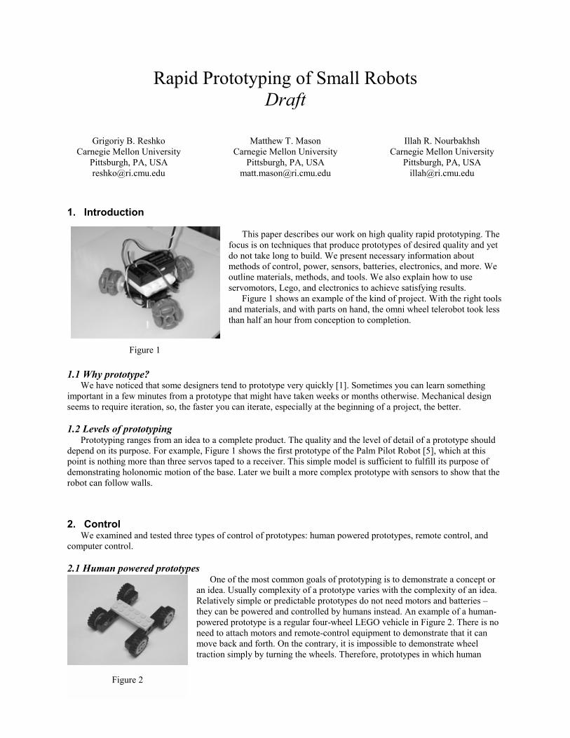
This paper describes our work on high quality rapid prototyping. The
focus is on techniques that produce prototypes of desired quality and yet do not take long to build. We present necessary information about methods of control, power, sensors, batteries, electronics, and more. We outline materials, methods, and tools. We also explain how to use servomotors, Lego, and electronics to achieve satisfying results.
Figure 1 shows an example of the kind of project. With the right tools and materials, and with parts on hand, the omni wheel telerobot took less than half an hour from conception to completion.
1.1 Why prototype? We have noticed that some designers tend to prototype very quickly [1]. Sometimes you can learn something
important in a few minutes from a prototype that might have taken weeks or months otherwise. Mechanical design seems to require iteration, so, the faster you can iterate, especially at the beginning of a project, the better.
1.2 Levels of prototyping
Prototyping ranges from an idea to a complete product. The quality and the level of detail of a prototype should depend on its purpose. For example, Figure 1 shows the first prototype of the Palm Pilot Robot [5], which at this point is nothing more than three servos taped to a receiver. This simple model is sufficient to fulfill its purpose of demonstrating holonomic motion of the base. Later we built a more complex prototype with sensors to show that the robot can follow walls.
2. Control We examined and tested three types of control of prototypes: human powered prototypes, remote control, and
computer control. 2.1 Human powered prototypes
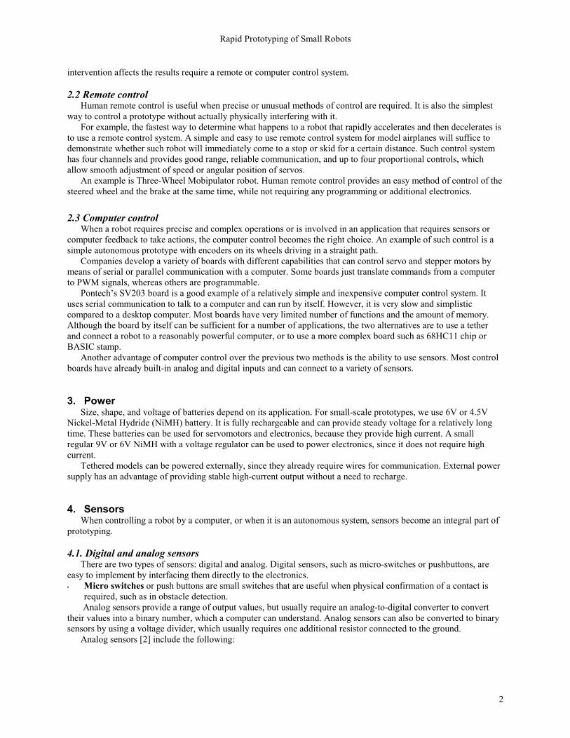
One of the most common goals of prototyping is to demonstrate a concept or an idea. Usually complexity of a prototype varies with the complexity of an idea. Relatively simple or predictable prototypes do not need motors and batteries they can be powered and controlled by humans instead. An example of a human-powered prototype is a regular four-wheel LEGO vehicle in Figure 2. There is no need to attach motors and remote-control equipment to demonstrate that it can move back and forth. On the contrary, it is impossible to demonstrate wheel traction simply by turning the wheels. Therefore, prototypes in which human
Figure 1
Figure 2
Rapid Prototyping of Small Robots
2
intervention affects the results require a remote or computer control system. 2.2 Remote control
Human remote control is useful when precise or unusual methods of control are required. It is also the simplest way to control a prototype without actually physically interfering with it.
For example, the fastest way to determine what happens to a robot that rapidly accelerates and then decelerates is to use a remote control system. A simple and easy to use remote control system for model airplanes will suffice to demonstrate whether such robot will immediately come to a stop or skid for a certain distance. Such control system has four channels and provides good range, reliable communication, and up to four proportional controls, which allow smooth adjustment of speed or angular position of servos.
An example is Three-Wheel Mobipulator robot. Human remote control provides an easy method of control of the steered wheel and the brake at the same time, while not requiring any programming or additional electronics.
2.3 Computer control
When a robot requires precise and complex operations or is involved in an application that requires sensors or computer feedback to take actions, the computer control becomes the right choice. An example of such control is a simple autonomous prototype with encoders on its wheels driving in a straight path.
Companies develop a variety of boards with different capabilities that can control servo and stepper motors by means of serial or parallel communication with a computer. Some boards just translate commands from a computer to PWM signals, whereas others are programmable.
Pontechs SV203 board is a good example of a relatively simple and inexpensive computer control system. It uses serial communication to talk to a computer and can run by itself. However, it is very slow and simplistic compared to a desktop computer. Most boards have very limited number of functions and the amount of memory. Although the board by itself can be sufficient for a number of applications, the two alternatives are to use a tether and connect a robot to a reasonably powerful computer, or to use a more complex board such as 68HC11 chip or BASIC stamp.
Another advantage of computer control over the previous two methods is the ability to use sensors. Most control boards have already built-in analog and digital inputs and can connect to a variety of sensors. 3. Power
Size, shape, and voltage of batteries depend on its application. For small-scale prototypes, we use 6V or 4.5V Nickel-Metal Hydride (NiMH) battery. It is fully rechargeable and can provide steady voltage for a relatively long time. These batteries can be used for servomotors and electronics, because they provide high current. A small regular 9V or 6V NiMH with a voltage regulator can be used to power electronics, since it does not require high current.
Tethered models can be powered externally, since they already require wires for communication. External power supply has an advantage of providing stable high-current output without a need to recharge.
4. Sensors When controlling a robot by a computer, or when it is an autonomous system, sensors become an integral part of
prototyping. 4.1. Digital and analog sensors
There are two types of sensors: digital and analog. Digital sensors, such as micro-switches or pushbuttons, are easy to implement by interfacing them directly to the electronics. • Micro switches or push buttons are small switches that are useful when physical confirmation of a contact is
required, such as in obstacle detection. Analog sensors provide a range of output values, but usually require an analog-to-digital converter to convert
their values into a binary number, which a computer can understand. Analog sensors can also be converted to binary sensors by using a voltage divider, which usually requires one additional resistor connected to the ground.
Analog sensors [2] include the following:
Rapid Prototyping of Small Robots
3
• Photoresistors are variable resistors that change their resistance due to the intensity of visible light. Phototransistors are similar, but provide greater sensitivity. Photodiodes have even greater sensitivity and respond rapidly to changes in illumination.
• Infrared sensors are used as proximity and reflectivity sensors and are almost unaffected by visible light. • Pyroelectric sensors respond to very small temperature changes, because its crystal induces a charge when it is
heated. • Bend sensors have conductive ink between two electrodes to give a variable resistance, depending upon the
degree of bending. Total resistance changes by a factor of about 3 to 5 as the bend sensor goes from straight to maximum bend.
• Force-sensing resistors are also based on conductive ink technology. They are very sensitive, and their resistance is changed by several orders of magnitude as force is applied.
• Rubbery ruler is a unique tube-like sensor that measures change in its length. Inside the tube has two wires, and when it stretches, the distance between the wires increases and the capacitance decreases.
• Microphones provide a way to add sound detection ability to a robot, although it usually requires additional electronics.
• Piezoelectric film sensors detect vibrations, changes in applied force, and changes in temperature and far-infrared radiation.
• Sonar sensors measure distance to an object. • Tilt sensors have a drop of electrolytic fluid between its electrodes. The amount of conduction between the
center electrode and each of the outer electrodes is determined by the degree to which the outer electrode is immersed in the electrolytic fluid.
• Shaft Encoders are important for precise control of motors and can be implemented using IR or light sensors. • Proprioceptive sensors measure the internal state of the robot, such as battery-level sensing, stall current
sensing, etc. 4.2. Infrared Rangefinders
Sharp GP2D12 infrared triangulation sensors (distributed by Acroname, Inc.) are very accurate rangefinders. These devices use linear position sensitive devices (PSD) and their measurements are accurate to approximately 1cm [Appendix A]. Sensors return their readings as variable voltage, ranging from 0 to 5 volts. Analog-to-digital converter is used to convert this analog value to digital reading ranging from 0 to 255. The sensors manual includes a graph of sensors value versus distance. Distance is approximated by using a power regression:
d(s) = 2141.7*s-1.07886
where d is distance in cm and s is 8-bit sensors value from 0 to 255.
IR sensors require significant amount of power. When using small boards, such as SV203, the sensors should be connected to unregulated 6V, instead of regulated 5V. Outputs of these sensors are connected to boards analog input pins.
5. Components 5.1 Fasteners
The most common type of fasteners in small-scale prototyping are little nuts and bolts. They come in variety of types and sizes. In our prototypes, we use 4-40 and 6-32 hexagonal head bolts and nuts, since they are appropriate for small-scale models. Usually, we use regular steel nuts, however plastic lock nuts and nylon insert nuts are useful for variable tightening of a bolt. 5.2 Materials Aluminum:
We found aluminum to be one of the best prototyping materials. It is lightweight and can be easily machined. A specific advantage of aluminum is its pliability. It can be bent at virtually any angle, although it depends on its thickness. ¼ plates can be bent up to 90°, whereas thin plates can be bent all the way to 180°. Aluminum can also be drilled, tapped, or cut more easily than other materials, such as steel.
Rapid Prototyping of Small Robots
4
Acrylic plastic: Acrylic plastic is also an interesting material. It can be cut and filed to provide almost perfect edge. It is also easy
to drill and tap. One of its advantages is that two pieces can be connected together in any fashion by using acetone or other solvent-welder. A solvent bond is similar to a weld, so it is extremely durable. Furthermore, unlike other glues, solvent securely connects two materials in very short time. Polycarbonate plastic:
Like acrylic, this plastic is easily machined. It can be cut, milled, and drilled. However, it is quite difficult to tap, because the material can be compressed. Its unique advantage is that it can be bent without heating, for example, using a brake. Most plastics either break during even minor bending or require to be heated. Another interesting property of polycarbonate plastic is its strength a ½ thick sheet is bullet proof.
5.3 Lego
Lego by itself is a great kit for prototyping. Complex parts, such as gear trains, arms, and steering mechanisms can be implemented quickly and easily using Lego parts for construction [3].
5.3.2 Lego structures
Sometimes it is faster to use Lego than to manufacture similar parts using usual materials. A good example is Lego wheels. Manufacturing a wheel is not an easy task and usually requires some time, whereas Lego wheels come in many shapes and sizes, such as a smooth-surfaced pulley or a large traction-wheel.
5.3.2 Lego Wheels
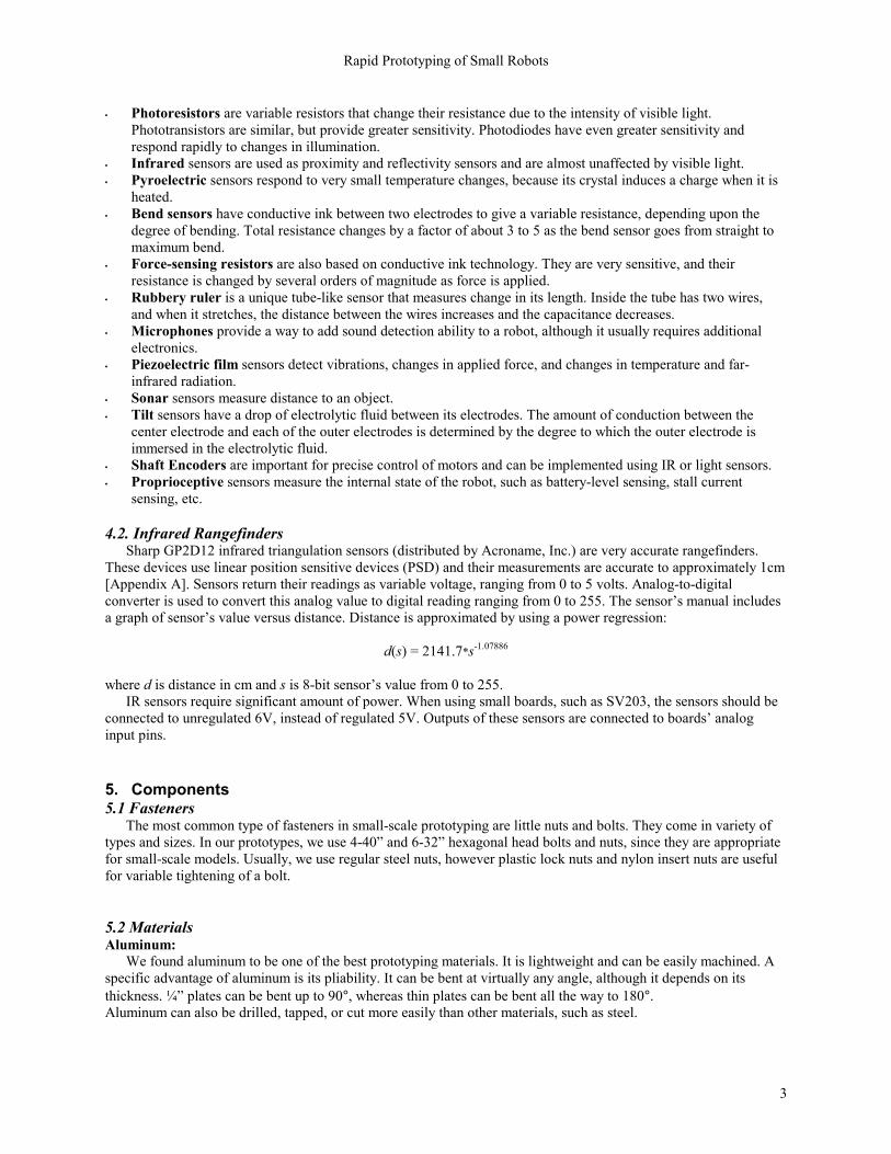
Small wheels and pulleys can be glued to servos with a heat-melt glue, whereas big Lego traction-wheels can be securely attached to CS60 servos, because servos connector fits nicely between wheels plastic and rubber.
An easy way to attach free spinning wheels to a prototype is to connect small Lego wheels to a 2x1 Lego beam with a hole in the middle by a Lego connector peg. The Lego beam is then glued to a structure, for example, an aluminum angle in Figure 3.
Larger wheels require two 4x1 or larger beams and a Lego axle that goes through the beams and the wheel.
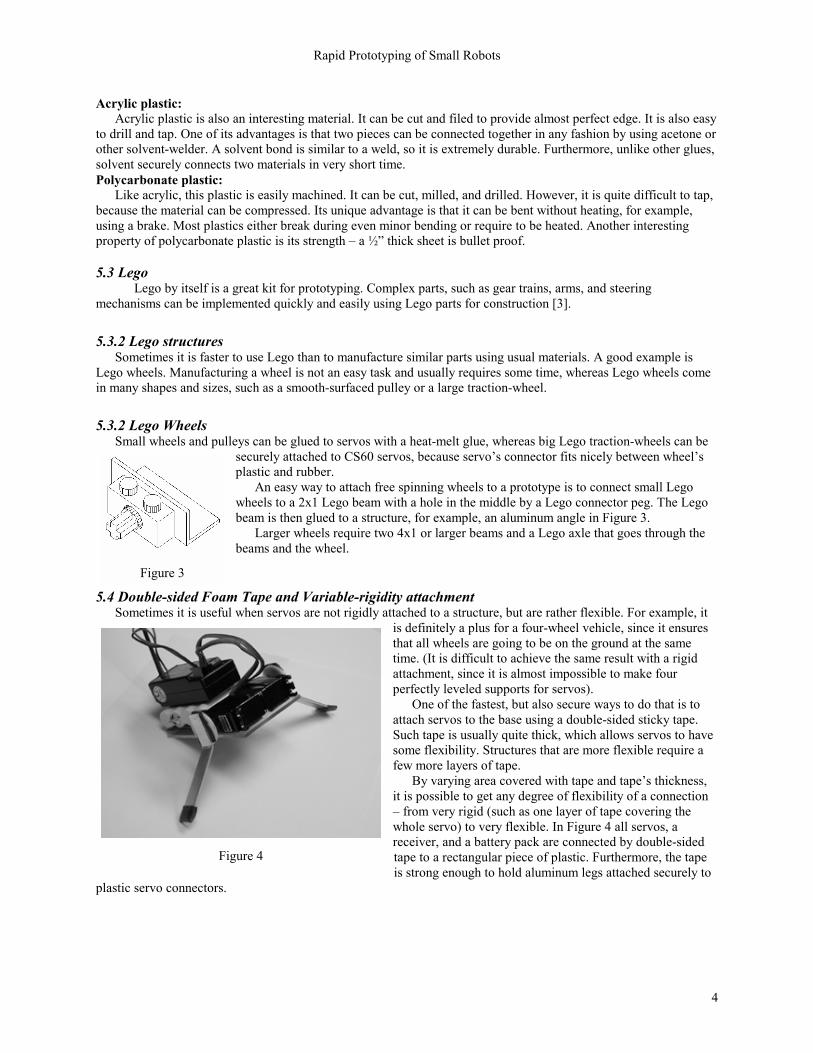
5.4 Double-sided Foam Tape and Variable-rigidity attachment Sometimes it is useful when servos are not rigidly attached to a structure, but are rather flexible. For example, it
is definitely a plus for a four-wheel vehicle, since it ensures that all wheels are going to be on the ground at the same time. (It is difficult to achieve the same result with a rigid attachment, since it is almost impossible to make four perfectly leveled supports for servos).
One of the fastest, but also secure ways to do that is to attach servos to the base using a double-sided sticky tape. Such tape is usually quite thick, which allows servos to have some flexibility. Structures that are more flexible require a few more layers of tape.
By varying area covered with tape and tapes thickness, it is possible to get any degree of flexibility of a connection from very rigid (such as one layer of tape covering the whole servo) to very flexible. In Figure 4 all servos, a receiver, and a battery pack are connected by double-sided tape to a rectangular piece of plastic. Furthermore, the tape is strong enough to hold aluminum legs attached securely to
plastic servo connectors.
Figure 3
Figure 4
Rapid Prototyping of Small Robots
5
5.5 Velcro A simple and yet secure way to attach a receiver or a battery to a robot is to use Velcro. A small 1x1 piece on a
robot and at the bottom of a battery or a receiver will securely hold it in place. Velcros advantage is that it can be detached this is not the case with other adhesives.
6. Servomotors
Servomotors can be used very efficiently for prototyping as primary drive motors, because of their mounting design, built-in gear reduction, and simple remote control. Lightweight and compact receiver-battery pack is also useful at relatively small models (ex. when a model is just twice the size of a receiver). Furthermore, servos can provide both types of actuation: angular position and velocity control. Angular position control means that servos input controls its position, whereas velocity control affects servos velocity.
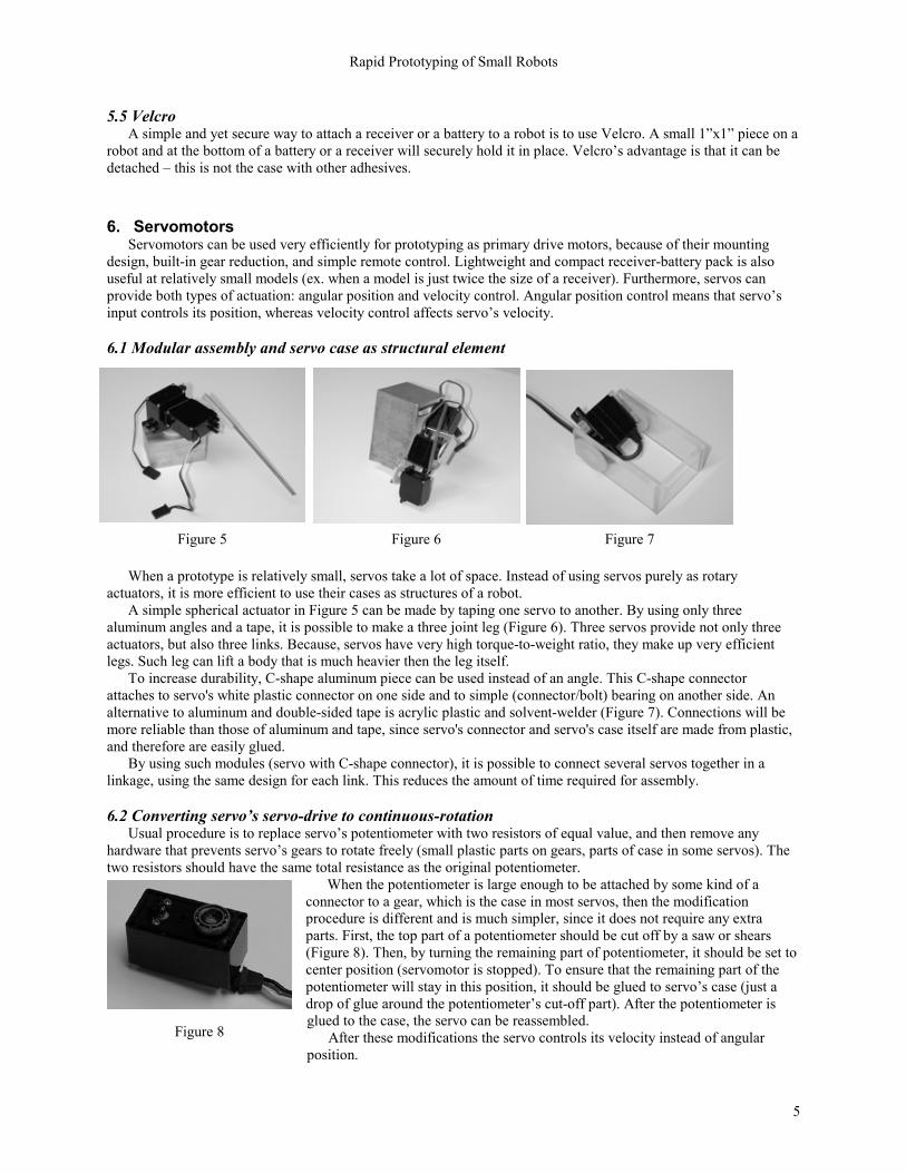
6.1 Modular assembly and servo case as structural element
When a prototype is relatively small, servos take a lot of space. Instead of using servos purely as rotary actuators, it is more efficient to use their cases as structures of a robot.
A simple spherical actuator in Figure 5 can be made by taping one servo to another. By using only three aluminum angles and a tape, it is possible to make a three joint leg (Figure 6). Three servos provide not only three actuators, but also three links. Because, servos have very high torque-to-weight ratio, they make up very efficient legs. Such leg can lift a body that is much heavier then the leg itself.
To increase durability, C-shape aluminum piece can be used instead of an angle. This C-shape connector attaches to servo's white plastic connector on one side and to simple (connector/bolt) bearing on another side. An alternative to aluminum and double-sided tape is acrylic plastic and solvent-welder (Figure 7). Connections will be more reliable than those of aluminum and tape, since servo's connector and servo's case itself are made from plastic, and therefore are easily glued.
By using such modules (servo with C-shape connector), it is possible to connect several servos together in a linkage, using the same design for each link. This reduces the amount of time required for assembly.
6.2 Converting servos servo-drive to continuous-rotation
Usual procedure is to replace servos potentiometer with two resistors of equal value, and then remove any hardware that prevents servos gears to rotate freely (small plastic parts on gears, parts of case in some servos). The two resistors should have the same total resistance as the original potentiometer.
When the potentiometer is large enough to be attached by some kind of a connector to a gear, which is the case in most servos, then the modification procedure is different and is much simpler, since it does not require any extra parts. First, the top part of a potentiometer should be cut off by a saw or shears (Figure 8). Then, by turning the remaining part of potentiometer, it should be set to center position (servomotor is stopped). To ensure that the remaining part of the potentiometer will stay in this position, it should be glued to servos case (just a drop of glue around the potentiometers cut-off part). After the potentiometer is glued to the case, the servo can be reassembled.
After these modifications the servo controls its velocity instead of angular position.
Figure 5 Figure 6 Figure 7
Figure 8

Rapid Prototyping of Small Robots
6
However, servomotors are not designed for speed-control and therefore their speed in not directly proportional to the 8-bit value (0255) sent to the board. The graph below shows a relation between sent values and actual speed of Cirrus CS30 servomotor:
Servos
-1-0.8-0.6-0.4-0.2
00.20.40.60.8
1
60.00
70.00
80.00
90.00
100.0
0
110.0
0
120.0
0
130.0
0
140.0
0
150.0
0
160.0
0
170.0
0
Value (0-255)
Spee
d (R
PS)
Figure 9
The curve through the points on the graph in Figure 9 is approximated to a reasonable degree by a cubic regression
s(v) = 39.81*v3 12.61*v2 + 22.12*v + 128.42 where s is servo value from 0 to 255 and v is servos velocity in revolution per second. 6.3 Pre-modified servomotors The methods described above are successful for modifying any servo. However, a company named MrRobot sells a number of already modified servos (Appendix C). These servos rotate smoothly, because additional lubrication is added to servos gears. No further modifications are needed, and the modified servos are inexpensive. 6.4 Attaching a servo to a structure
Servo can be easily attached to an angle, by milling (punching or cutting out) a slot, drilling four holes, and attaching the servo using four bolts (Figure 10). The slot should be as wide as servos base. Holes should be the same diameter as the mounting holes on a servo. This attachment will be extremely secure, because the servo is connected to an angle by four bolts and has the other surface of an angle as an additional horizontal support. Plastic on servos acts as a lock-washer, preventing bolts from loosening.
This servo-angle assembly can be attached virtually to any surface using only two bolts.
Figure 10
Rapid Prototyping of Small Robots
7
S1 PWM S1 GND S1 +V
S3 PWM S3 GND S3 +V GND
+V
BIT 3
BIT 2
BIT 1
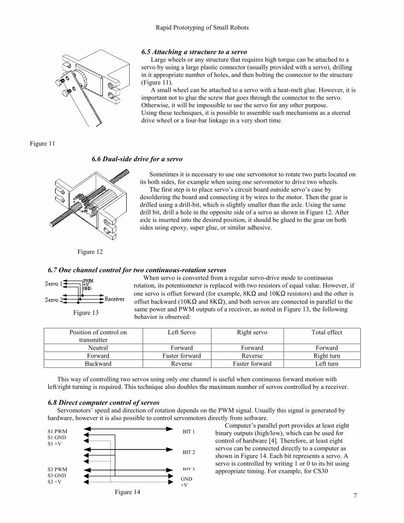
6.5 Attaching a structure to a servo Large wheels or any structure that requires high torque can be attached to a
servo by using a large plastic connector (usually provided with a servo), drilling in it appropriate number of holes, and then bolting the connector to the structure (Figure 11).
A small wheel can be attached to a servo with a heat-melt glue. However, it is important not to glue the screw that goes through the connector to the servo. Otherwise, it will be impossible to use the servo for any other purpose. Using these techniques, it is possible to assemble such mechanisms as a steered drive wheel or a four-bar linkage in a very short time.
6.6 Dual-side drive for a servo
Sometimes it is necessary to use one servomotor to rotate two parts located on
its both sides, for example when using one servomotor to drive two wheels. The first step is to place servos circuit board outside servos case by
desoldering the board and connecting it by wires to the motor. Then the gear is drilled using a drill-bit, which is slightly smaller than the axle. Using the same drill bit, drill a hole in the opposite side of a servo as shown in Figure 12. After axle is inserted into the desired position, it should be glued to the gear on both sides using epoxy, super glue, or similar adhesive.
6.7 One channel control for two continuous-rotation servos When servo is converted from a regular servo-drive mode to continuous
rotation, its potentiometer is replaced with two resistors of equal value. However, if one servo is offset forward (for example, 8KΩ and 10KΩ resistors) and the other is offset backward (10KΩ and 8KΩ), and both servos are connected in parallel to the same power and PWM outputs of a receiver, as noted in Figure 13, the following behavior is observed:
Position of control on
transmitter Left Servo Right servo Total effect
Neutral Forward Forward Forward Forward Faster forward Reverse Right turn
Backward Reverse Faster forward Left turn This way of controlling two servos using only one channel is useful when continuous forward motion with
left/right turning is required. This technique also doubles the maximum number of servos controlled by a receiver.
6.8 Direct computer control of servos Servomotors speed and direction of rotation depends on the PWM signal. Usually this signal is generated by
hardware, however it is also possible to control servomotors directly from software. Computers parallel port provides at least eight
binary outputs (high/low), which can be used for control of hardware [4]. Therefore, at least eight servos can be connected directly to a computer as shown in Figure 14. Each bit represents a servo. A servo is controlled by writing 1 or 0 to its bit using appropriate timing. For example, for CS30
Figure 11
Figure 12
Figure 14
Figure 13
Rapid Prototyping of Small Robots
8
servomotor, 1ms HIGH followed by 4ms LOW drives servomotor forward and 4ms HIGH / 1ms LOW drives it backward. All servos can be controlled simultaneously. The following C++ function drives two servos forward and two backward:
// DATA is LPT1 data port (usually 0x0378)// outportb() outputs value to portvoid Drive()while (no_interrupt)// 0011: bits 1 and 2 – HIGH, bits 4 and 8 - LOWoutportb(DATA, 0x03); // bits 1 and 2 (1+2=3)delay(1); // 1ms delay// 1100: bits 1 and 2 – LOW, bits 4 and 8 - HIGHoutportb(DATA, 0x0C); // bits 4 and 8 (4+8=C)delay(4); // 4ms delay
Although this method requires a ribbon of cables, since each servo needs a separate PWM input, it eliminates the
need for any additional hardware. Power cables of small servomotors connect directly to one or several HIGH pins of a parallel port, whereas
ground wires connect directly to GND pins. This eliminates a battery, which might be unnecessary for a small robot.
6.9 Servo controller boards Although, direct computer connection to servos provides a simple and inexpensive way to control them, other
alternatives are usually more preferable. Servo controller boards, such as Pontechs SV203 board, are often used to control servomotors and read inputs.
SV203 board can simultaneously control up to eight servos and has five analog-to-digital inputs. Short strings are used for communication between the board and a computer. For example, M128 moves a selected servo to position 128.
Sampling of sensors is also easy. A computer sends a request to sample a desired sensor, and then receives a value of the sensor followed by ASCII character 13.
This provides a simple user-friendly interface. Another advantage of such boards is their small size and stand-alone ability. For example, SV203B is 2 x 1 board, which can control sensors and motors without being connected to a computer. 7. Machining
We have found that the two most useful machines that are needed are a mill and a band saw. Brakes, shears, presses, and others are definitely useful, but are not required. • Mill is probably the most versatile machine and very useful. It can smoothen edges after a band saw and
perform various high-quality vertical-milling operations. Using a mill-chuck can also work as a high-precision drill eliminating a need for a drill press.
• Drill press is used to drill straight or tapered holes. Drill bits produce straight holes, whereas countersinks make holes tapered. Countersinks can also deburr holes after drilling.
• Band saw is required to cut materials. • Brake and shear are useful for good quality bending and breaking of sheet metal. When a shear cuts a material,
it usually has a very even smooth edge. • Lathe is used for manufacturing of round cylinder-based parts. • Taps are used to make threads in holes (for bolts) when use of nuts presents a problem or is not required (for
example, attaching something to a large aluminum block). For our purposes, 4-40 tap and No.43 drill bit are used for 4-40 bolts and 6-32 tap and No.36 drill bit for 6-32 bolts.

Rapid Prototyping of Small Robots
9
8. Electronics Electronics is one of the main components of most robots, and therefore is an integral part of prototyping. Refer
to Jones & Flynn [2] and Horowitz & Hill [6] for additional information. 8.1 Circuit boards
Bread boarding is probably most useful for initial testing and debugging, since it is inexpensive, and components and connections can be easily rearranged. However, the component density is very low, and the resulting board is usually several times bigger than a printed circuit board (PCB). In addition, capacitance between rows can seriously affect high-frequency circuits.
Other prototyping boards include wire-wrap, Scotchflex and Speedwire. Wire wrap uses special pins and wires, which are curled around these pins. Both, Scotchflex and Speedwire, use sockets and plug strips to connect components. Printed circuit boards and multi-layer boards are rarely used for prototyping, but are great for the final production of the circuit. 8.2 Connectors
Connectors are widely used in electronics. Probably the most common type of connectors are terminal plug strips and terminal sockets. When there are many wires, several terminal strips are glued together to form one wide connector.
It is also useful to key all connectors. Keying is a way of making sure that you cannot put the connector backwards. An example will be to have one additional terminal or to cut off an unused one.
Other connectors, such as DB25 or DB9, are usually used for specific connections such as a printer port on a computer, but can also be used with the same efficiency on a robot.
9. Conclusion and results Using parts obtained from manufacturers listed in Appendix C, we constructed many prototypes to prove that
various techniques described in this text can be directly applied to create a working robot. Small robots shown in Appendix B demonstrate various concepts of rapid prototyping.
Although an important step in building a robot is creativity and problem solving, many concepts of this paper can help amateur as well as professional robot developers.
Rapid Prototyping of Small Robots
10
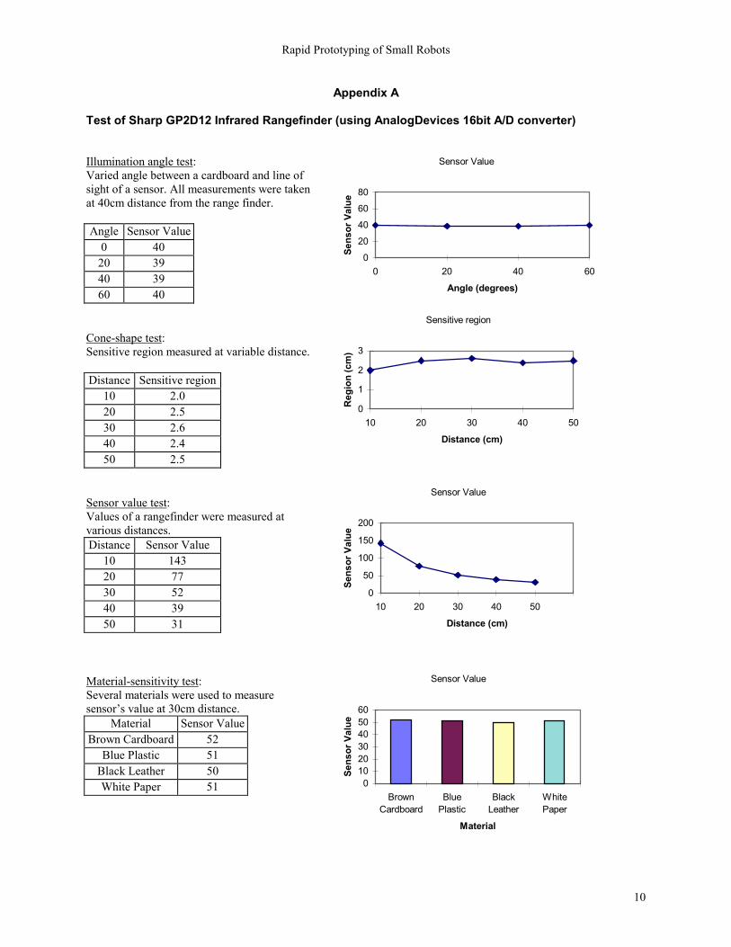
Appendix A Test of Sharp GP2D12 Infrared Rangefinder (using AnalogDevices 16bit A/D converter)
Illumination angle test: Varied angle between a cardboard and line of sight of a sensor. All measurements were taken at 40cm distance from the range finder. Angle Sensor Value
0 40 20 39 40 39 60 40
Cone-shape test: Sensitive region measured at variable distance. Distance Sensitive region
10 2.0 20 2.5 30 2.6 40 2.4 50 2.5
Sensor value test: Values of a rangefinder were measured at various distances. Distance Sensor Value
10 143 20 77 30 52 40 39 50 31
Material-sensitivity test: Several materials were used to measure sensors value at 30cm distance.
Material Sensor Value Brown Cardboard 52
Blue Plastic 51 Black Leather 50 White Paper 51
Sensor Value
0
20
40
60
80
0 20 40 60
Angle (degrees)
Sens
or V
alue
Sensitive region
0
1
2
3
10 20 30 40 50
Distance (cm)
Reg
ion
(cm
)
Sensor Value
0
50
100
150
200
10 20 30 40 50
Distance (cm)
Sens
or V
alue
Sensor Value
0102030405060
BrownCardboard
BluePlastic
BlackLeather
WhitePaper
Material
Sens
or V
alue
Rapid Prototyping of Small Robots
11
Appendix B
Examples of working prototypes:
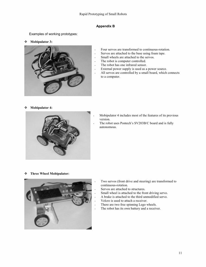
Mobipulator 3:
• Four servos are transformed to continuous-rotation. • Servos are attached to the base using foam tape. • Small wheels are attached to the servos. • The robot is computer controlled. • The robot has one infrared sensor. • External power supply is used as a power source. • All servos are controlled by a small board, which connects
to a computer.
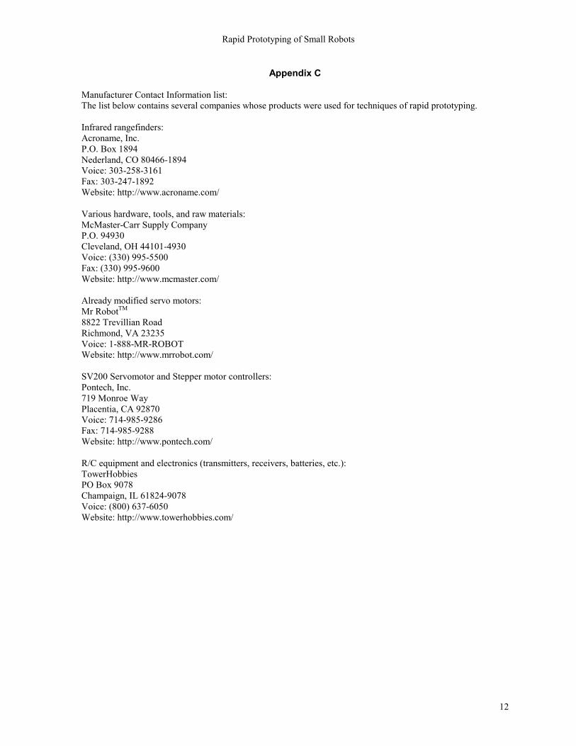
Mobipulator 4:
• Mobipulator 4 includes most of the features of its previous version.
• The robot uses Pontechs SV203B/C board and is fully autonomous.
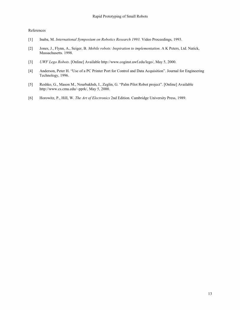
Three Wheel Mobipulator:
• Two servos (front drive and steering) are transformed to continuous-rotation.
• Servos are attached to structures. • Small wheel is attached to the front driving servo. • A brake is attached to the third unmodified servo. • Velcro is used to attach a receiver. • There are two free spinning Lego wheels. • The robot has its own battery and a receiver.
Rapid Prototyping of Small Robots
12
Appendix C
Manufacturer Contact Information list: The list below contains several companies whose products were used for techniques of rapid prototyping. Infrared rangefinders: Acroname, Inc. P.O. Box 1894 Nederland, CO 80466-1894 Voice: 303-258-3161 Fax: 303-247-1892 Website: http://www.acroname.com/ Various hardware, tools, and raw materials: McMaster-Carr Supply Company P.O. 94930 Cleveland, OH 44101-4930 Voice: (330) 995-5500 Fax: (330) 995-9600 Website: http://www.mcmaster.com/ Already modified servo motors: Mr RobotTM 8822 Trevillian Road Richmond, VA 23235 Voice: 1-888-MR-ROBOT Website: http://www.mrrobot.com/ SV200 Servomotor and Stepper motor controllers: Pontech, Inc. 719 Monroe Way Placentia, CA 92870 Voice: 714-985-9286 Fax: 714-985-9288 Website: http://www.pontech.com/ R/C equipment and electronics (transmitters, receivers, batteries, etc.): TowerHobbies PO Box 9078 Champaign, IL 61824-9078 Voice: (800) 637-6050 Website: http://www.towerhobbies.com/
Rapid Prototyping of Small Robots
13
References
[1] Inaba, M. International Symposium on Robotics Research 1993. Video Proceedings, 1993.
[2] Jones, J., Flynn, A., Seiger, B. Mobile robots: Inspiration to implementation. A K Peters, Ltd. Natick, Massachusetts. 1998.
[3] UWF Lego Robots. [Online] Available http://www.coginst.uwf.edu/lego/, May 5, 2000.
[4] Anderson, Peter H. Use of a PC Printer Port for Control and Data Acquisition. Journal for Engineering
Technology, 1996.
[5] Reshko, G., Mason M., Nourbakhsh, I., Zeglin, G. Palm Pilot Robot project. [Online] Available http://www.cs.cmu.edu/~pprk/, May 5, 2000.
[6] Horowitz, P., Hill, W. The Art of Electronics 2nd Edition. Cambridge University Press, 1989.