rank strand electric - theatrecrafts.com · maintenance handbook for jt m dimmer racks rank strand...
TRANSCRIPT

MAINTENANCE
HANDBOOK
FOR
JT M DIMMER RACKS
RANK STRAND ELECTRIC 29 King Street London WC2 Telephone 01-836 4444 Telegrams Spotlite London WC2
A DIVISION OF
RANK AUDIO VISUAL LIMITED
05301-034

05301-034/ Title/ Page 2
Issue 2
SCOPE
This handbook contains information normally required for maintenance and servicing of the equipment. Commissioning and operational information, where relevant, is covered in the associated User's Handbook .
SER VICE ASSISTANCE
For assistance with servicing or maintenance, please contact the nearest Regional Office, Agent or Associate Company (see list attached at the end of this handbook) and state the Order Reference, Equipment Reference or other relevant information as well as an indication of the fault-symptom encountered.
Revision/amendment since last issue of document:
on margin denotes minor changes. against headings or illustration numbers denotes major revisions .
7102
C
05301-034 Page 1 of 13
MAINTENANCE HANDBOOK JTM 10/20-way DIMMER RACKS
1.
2.
3.
4.
5.
CONTENTS
Circuit Description
1. 1. Dimmer Module 1. 2 . Trigger Unit
Check and Test Procedure
2. 1. Racks 2. 2. Dimmer Modules 2. 3. Trigger Cards
Dismantling/Replacement Information
3. 1. 3. 2. 3. 3.
Dimmer Modules Thyristors Trigger Unit circuit-boards
Maintenance Information
4.1. 4. 2 .
Routine Maintenance Fanlt Diagnosis
Parts Lists
5. 1. Complete Assemblies/ Sub- assemblies 5 . 2. Components
Rack Wiring diagram
SUPPLEMENTS
Page
2
2
3
4
6 6 6
8
8 8
8
8
8 8
10
10 11
13
PCB-034: Service Aid Information on Printed-Circuit Boards.
1-014: List of Regional Offices, Agents and Associate Companies .
ASSOCIATED PUBLICATIONS
05301-032: User's/Commissioning Handbood for JTM Dimmer Racks.
7102 Issue 2

05301-034/Page 2 of 13
1. CIRCUIT DESCRIPTION
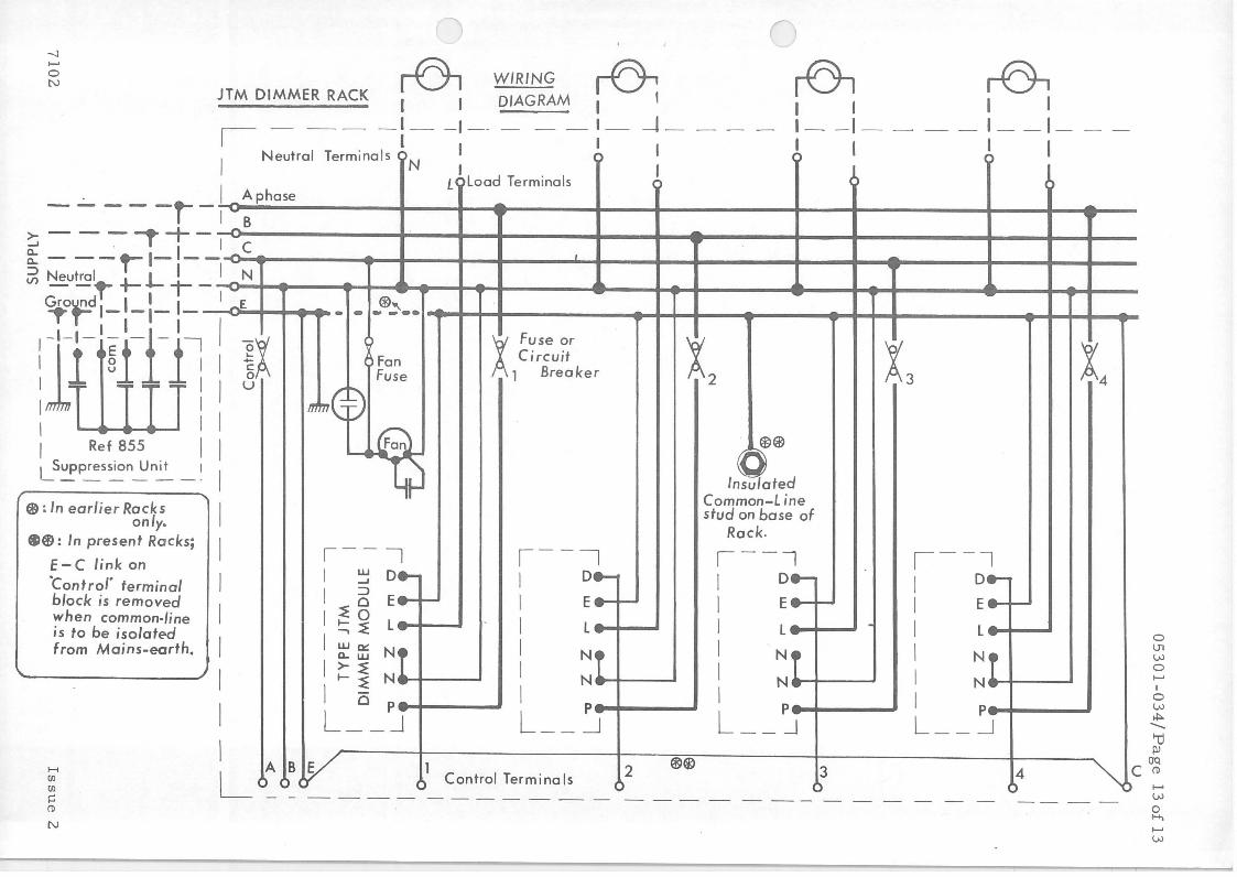
See Wiring diagram on page 13.
1. 1. DIMMER MODULE
1. 1. I. PRINCIPLE OF OPERATION
See Fig. I. I. I.
Inverse-parallel connected thyristors SCRI and SCR2 are supplied with firing pulses from the Trigger Unit such that each thyristor is switched on at the same relative instant during the appropriate conductive half-cycle of mains supply. The value of control-signal input to the Trigger Unit determines the firing instant; since each thyristor, once switched on, conducts till the end of the half-cycle, the control signal also determines the conduction phaseangles of the SCRs and hence the averaged a-c output to the load. With zero control-signal input, the SCRs are triggered 'on I at or near the termination of their half-cycles supplies, giving zero or a required minimum a-c output to load; with maximum control-signal (negative d-c or half-wave rectified a-c), the SCRs are triggered 'on' near the start of respective half-cycles, giving maximum a-c output to load.
N
..L:
Fa:
Fb:
C2: Rl:
Is sue 2
Fb ~-------------c-- - -I I 120
1
------
11107
Trigger
11u--------16~- ..
1 9
Un it
~-~r-r-J
Common-Line
Control signal
Fuse on 200-ZS0V Modules; Circuit-breaker on 110-IZ0V Modules.
Fu'se on 110-IZ0V Modules
SCR2
llfi/ter FIG.1.1.1.
0, luF 300V a-c ) )
on installations with poor mains -impedance I00Q SW
7102
C
7102
05301-034/Pag e 3 of 13
1. 1. 2. CIRCUIT DETAILS
Transformer T2 supplies 14V a-c to t e rm i nals 7 and 9 of the Trigg e r Unit . The control-signal input to Trigger Unit is applied via terminal D of the Dimmer Module, to terminal 3 of Trigger Unit, relative to terminal E of Dimmer Module and terminal 5 of Trigger Unit. This signal may be 24V a-c half-wave-rectified or a d-c signal, applied via a 1 OK ohms resistor.
Firing pulses to the SCRs are applied via terminal-pairs 11/ 12 and 14/ 16 of Trigger Unit.
The inductive Filter Unit serves to extend the rise-time of load output when the SCRs are switched 'on', and also to filter any switch-on transients, thus giving an output waveform suitable for interference-free operation of the lamps.
NOTE: As shown in the Wiring Diagram on page 13, terminals E of all Modules were connected to the mains -earth stud ( on Rack framework) in the earlier Racks. In present Racks, terminals E of all Modules and terminal C of the 'Control' terminal block are connected to an insulated 'Common-line I stud, and a link is provided between . terminals C and E on the 'Control' terminal block. This link is removed when the control application requires isolation of common-line from the mains -earth.
1. 2 . TRIGGER UNIT: Ref: 932/ 14 or 934 (see para. 5. 1. 2)
NOTE: Ref. 932/ 14 Unit is designed for wired-in mounting and Ref. 934 Unit is designed for plug-in mounting on the Dimmer Module.
1. 2 . 1. SUMMARY
An exponential saw-tooth wave -form, with a repetition rate of one per halfcycle of the mains -supply, is generated and compared with the input controlsignal, to switch 'on' a pulse-generator at the appropriate instant during each half-cycle; the 1ramp 1 wave-form and the pulse-generator are re-set at the termination of each half -cycle of mains -supply.
1. 2 . 2. CIRCUIT DETAILS
See Fig. 1. 2. 2. 1. for the circuit diagram; See Fig. 1. 2. 2. 2. for nominal waveforms.
NOTE: In the following description, unless otherwise stated, all voltages (and wave-form details) are nominal values and are referred to the common-line terminal 5 .
Bridge-connected MRI rectifies the 14V a-c supply fed to terminals 7 and 9 • (waveform 1) to give a series of negative-half-cycle output (waveform 2) at Rl-MR2 junction. MR2 isolates C6 from the 'positive I peaks of the above ~
outputand allows C6 to be charged negative to about -16V. R9 and MR4
Issue 2
05301-034/ Page 4 of 13
provide stabilised -12V supply, by-passed by C3, to terminal 1 and the circuits of VT2-to-VT5.
VT 1 is switched off for a 500uS period coincident with the 'positive' peaks of MRI output (i. e. coincident with the zero-crossover instants of a a-c mainssupply), and is switched on for the rest of each half-cycle. With VT 1 off, VT2 is switched on, discharging C2 and switching VT4 on; this in turn switches VT5 on and VT6 off. With VT! on, VT2 is switched off; since C2 had been previously discharged, VT4 remains on, and capacitor C2 is charged negative via R5 and the base-emitter junction of VT4 (wave-form 4).
The input control-signal to terminal 3 is smoothed by C4, potential-divided by R8-VR2 and applied to VT3 base. VRl provides gain-controlling feedback to d-c amplifier VT3. For given settings of VRl and VR2, the value of controlsignal input determines the collector-current of VT3 and hence the potential, due to this current alone, at VT3 collector and VT4 emitter. C2 has to charge to approximately this potential before VT4 is switched off, in turn switching VT5 off, and switching on the blocking oscillator circuit of VT6 to generate a l00uS pulse-train (waveform 5) which is fed, via the secondaries of Tl, to the associated thyristors.
Thus, with zero signal input to terminal 3, the low collector current of VT3 requires C2 to charge to a higher voltage to switch VT4 off; hence 'firing' occurs near the end of each half-cycle. With a negative signal input, the higher collector current of VT3 requires C2 to charge to a lower voltage to switch VT4 off; hence the 'firing' instant is time-advanced in each half-cycle.
When VT6 is switched off coincident with the zero crossover instants of mains -supply, the pulses stop. Diode MR6 limits the back-emf in T 1 primary to a safe value when VT6 is switched off.
1. 2. 3. BOTTOM AND TOP SET ADJUSTMENTS
VRl (BOTTOM SET) is · normally set to ensure that, with zero input, VT4 does not turn off till near the end of each half-cycle; VR2 (TOP SET) is set with maximum (negative) signal input, to give maximum output from the associated thyristors.
2 . CHECK AND TEST PROCEDURE:
NOTE: Use a voltmeter with sensitivity of not less than !OK ohm/V for all voltage measurements other than load output voltages; see NOTE in para. 4 below; see para. 4. 1 of User's Handbook for output measurements .
A double-beam oscilloscope is advisable for waveform-checks since this enables comparison with mains - supply waveform.
Issue 2 7102

...
7102
05301-034/Page 5 of 13
MR2 • r:G:16 II
RI II R// ir • /4
·~12 1 R/2 I
II 7 R/3
9
5 3
I C4 ~ VR2
Common 5 + F /G.l .2.2 .I. Line
{20mS(50Hz)
I /6.lmS (60Hz) ~
G) a-c supply to terminals 7 &9 0 I
® at Rl -MR2 j'.mction
0 at VT 1 collector/VT2 base
0 across C2 ~ ... , ... ,
C
~ ' I '\,. I ' I ...,,
G) at VT6 collector 0t a Ill b 111 111111 11111 c
-1 s v-t----- ~ --!lUll.JlUI.-
© output waveform across load
0 pulse waveform 5 expanded
0-n n ,, j L_j ~00µ5 [ Hatch e d areas show
load energisation
FIG.l.2.2.2.
I I .~ BOOµS
z e ro control signal
small (negative) control signal
large (negative) control signal
Issue 2

05301-034/ Page 6 of 13
2. 1. RACKS
Check that the a-c supply to the Rack is switched on; note that the neon on the fuse-panel or circuit-breaker panel indicates presence of a-c supply to the fan only; failure of the fan fuse will switch off this neon to give 'fan-off' indication; note also that, with the above panel hinged open, the fuse-holder or circuitbreaker terminals are 'live' with a-c supply to rack switched on.
Check that the force-vent fan is operating satisfactorily; the fan supply is separately fused.
The 'Control' fuse or circuit-breaker protects the a-c supply to the associated Desk. The 10 (or 20) other fuses/ circuit-breakers are numbered to correspond with the Dimmer Modules whose a-c supply and load circuits are thus protected.
2. 2. DIMMER MODULES
NOTE: All voltages, unless otherwise stated, are nominal values referred to common-terminal E on the Module and terminal 5 on Trigger -card. Note also that the thyristor heat-sinks are 11live 11
•
See Figures 2. 2 and 2. 3 in the User's Handbook 05301-032.
Check the primary input voltage (200 -250V) and secondary output ( 14V) of transformer T2.
Check input voltage to terminal D (relative to E) and output voltage to load.
2. 3 . TRIGGER CARDS
Check the d-c voltages across C6 (-16V ± 10%), and C3 (-12V ± 10%).
Check that the input voltage at terminal 3 varies from zero to a negative vc!,lue (of the order of 7V or so) as the associated channel-lever, and master-fader if any , are operated.
Check the following waveforms (see Fig. 1. 2. 2 . 2.):
Switching waveform at VT 1 collector; 'Ramp' waveform at VT2 collector (across C2); Pulse waveform at VT 5 collector.
Check setting up of VRl and VR2 on Trigger Unit as detailed in para. 4. 1 of the User's Handbook 05301-032 .
Is sue 2 7102
05301-034/ Page 7 of 13
TABLE 3.2 i
Module Thyristor
Ref. V & KW Make Type Tightening Torque
No. Rating (Note 1) No.
lb-in Nm
JTMl0 240V, W-H CS22M/CF 30-35 3.37-3.93 or lKW W-H Ul211/B5 42 4.72 JTMl0C AEI RS 1/5 30-35 3.37-3.93
IRC 16RC60 20-25 2.24-2.8
JTM20 240V, W-H CS21M/CF 30-35 3.37-3.93 or 2KW W-H Ul210/B5 42 4.72 JTM20C AEI RS9/5 30-35 3.37-3.93
IRC 30RCS60 25-30 2.8-3.37
JTM20L 120V, W-H Ull08/3 42 4.72 or 2KW AEI CR30201A 85-100 9. 64-11. 23 JTM20LC AEL CR30203A 85-100 9.64-11.23
AEI CR30303A 85-100 9.64-11.23 AEI RS5/3 30-35 3.37-3.93 AEI RS9/3 30-35 3.37-3.93 IRC 40RCS30 25-30 2.8-3.37
JTM30L 120V, W-H Ull08/3 42 4 . 72 or 3KW AEI CR30201A 85-100 9 . 64-11.23 JTM30LC · AEI CR30203A 85-100 9.64-11.23
AEI CR30303A 85-100 9.64-11.23 AEI RS5/3 30-35 3.37-3.93
( IRC 40RCS30 25-30 2.8-3.37
JTM50C 240V, W-H CS31MC/F 40-50 4.5-5.6 5KW , W-H Ull08/5 42 4.72
AEI CR30403A 85-100 9.64-11.23 AEI CR30503A 85-100 9.64-11.23 AEI RS3/6 85 9.64 IRC 40RCS60 25-30 2.8-3.37
JTM60L 120V, W-H 42T3 34,:, 94.3 6KW W-H Ull09/ 3 126 141
AEI RS7/4 85-100 9. 64-11. 23 IRC 71RA30 120-160 134-180
Note 1 : W-H = Westinghouse AEI = AEI Semi-conductors
IRC = International Rectifier
_,_ : on each base -mounting bolt -,-
7102 Issue 2

05301-034/Page 8 of 13
3. DISMANTLING/ REPLACEMENT INFORMATION
3. 1. DIMMER MODULES
In early versions of Dimmer Racks, the Modules were secured to the rack by four screws through the base-plate. In the present Racks, the Modules are secured by nuts on to studs provided in the Rack.
3. 2. THYRISTORS
Do not attempt to remove the heat-sinks from the module base-plate; unsolder or disconnect the thyristor gate and cathode connections, and remove the thyristor from its heat-sink.
When replacing a thyristor: (a) use a replacement of the same type as the one removed from the module; note that alternative types listed for certain modules in the table below are not direct replacements but are electrical alternatives only, especially when the manufacturers differ; (b) ensure that the correct tightening torque is applied on the nut or nuts securing the thyristor to its heat-sink {see Table 3. 2. on Page 7).
3. 3. TRIGGER UNIT - PRINTED-CIRCUIT BOARDS
Where these are wired-in,, they are secured to the top of the thyristor heatsinks by four nylon studs.
4. MAINTENANCE INFORMATION
NOTE: Only a qualified electrician familiar with the equipment should undertake replacement or other maintenance work in the racks.
Always switch off the rack-supply isolator before undertaking any maintenance work on its interior. Remember that high voltages are present at thyristor heat-sinks and associated wiring, and take suitable precautions when testing or measuring with the supply switched on.
4. 1. ROUTINE MAINTENANCE
The racks themselves require little routine maintenance apart from some attention to the fan (see paragraph 4. 1. 1. below) and periodical inspection of associated wiring and connections and, in very dust-prone environments, inspection of the rack-interior for any accumulation of dust; use a soft brush and suction-type low-pressure air-cleaner to effect the necessary cleaning.
4 . 1. 1. FANS
The fan manufacturers advise that MK 3B and MK 4B - 6 11 - 1400 rpm fans
have sealed lubrication for the bearings and this is normally adequate for 10, OOO hrs . operating time; contact the Maintenance Department of Rank Strand Electric Limited for bearing replacement at the end of this period.
Is sue 2 7102

C
(
7102
05301-034/Page 9 of 13
4. 2. FAULT DIAGNOSIS
4. 2. 1. RACKS
Failure of a-c supply to associated Desk: Check 'Control' fuse or circuitbreaker.
Failure of force-vent fan and the neon indicator: Check the fuse above the 'Fan' label.
Complete failure of output to load and of a-c supply to the associated Module: Check the numbered fuse.
Failure of output to load only: Replace the Dimmer module as a complete unit and set up VRl and VR2 as in para. 4. 1 of the User's Handbook. If the module has a plug-in Trigger-card, replace this card first, to check if this is the faulty unit. For detailed servicing, where it is convenient to do so, the procedure given in para. 4. 2. 1. 2. may be helpful.
4. 2. 1. 1. Check presence of 'firing I pulses at VT 6 collector on the Triggercard (see Fig. 1. 2. 2. 2.) with an oscilloscope; if this is satisfactory, check the load and thyristor circuits - see below; if the pulse-check is not satisfactory, replace the trigger-card unit or check it in detail as in para 2. 3.
4. 2. 1. 2. Insufficient output to load: Confirm, by means of the test above, that the Trigger-card is satisfactory. Check waveform of output voltage across load, comparing it with the mains-supply waveform if possible - see Fig. 1.2.2.2.
If alternate half-cycles of output are missing (see Fig. 4. 2. A), this indicates failure of one thyristor; check a-c supply to anode, and continuity from cathode to load; replace thyristor if the above two sets are OK; see para 3. 2.
FIG.4.2A. ~ or ~ \ , \ ......... ,.,/
FIG.4.28. ,~or ~
If alternate half-cycles of output waveform are complete half-cycles (see Fig. 4. 2. B), this indicates a short-circuit across (or between) the anode and cathode of the respective thyristor; replace the thyristor.
4. 2. 2. TRIGGER-CARD UNITS
Specially where these units are plug-in items and also on wired in items, the following check may help to isolate a faulty unit:
Issue 2

05301-034/Page 10 of 13
Check 14V a-c supply to terminals 7 and 9.
Check that the control voltage at terminal 3 can be varied from zero ( or other minimum value) to -15V (or other maximum value, as set-up on site); if these tests are satisfactory, check -presence of "firing" pulses at VT5 collector (the transistor-case) and that the timing of these pulses is controlled by the input voltage as shown in Fig. 1. 2 . 2. 2. If this test is not satisfactory, replace the Trigger card and set VRl and VR2 as _in para. 4. 1. of the User's Handbook.
4. 2 2 . 1. DETAILED TESTS ON TRIGGER CARD
See para . 2. 3.
4.2 3. TRANSFORMER-FED LOADS
Figure 4 . 2. 3. illustrates the typical external connection to Land N terminals of a Dimmer Module when used, for example, with a step-down transformer and a low-voltage lamp . Open-circuit of the fixed load across the transformer primary in such applications may result in overheating of, and damage to, the transformer if simultaneously the secondary load or circuit also becomes opencircuit; this is due to half-waving and the resultant large d-c component of currents in the transformer.
Fixed resistive (or preferably filament type) load of at least l00W rating
FIG.4.2.3.
5 . PARTS LIST INFORMATION
5. 1
5 . 1. 1.
5. 1. 2.
Is sue 2
COMPLETE ASSEMBLIES AND SUB -ASSEMBLIES
DIMMER MODULES
Rating
lKW, 200-250V 2KW, 200-250V 2KW, 110-120V 3KW, 110-120V 5KW, 200-250V 6KW, 110-120V
Ref. No.
JTMl0 or l0C JTM20 or 20C JTM20L or 20LC JTM30L or 30LC JTM50C JTM60L with filter separate.
TRIGGER-UNIT PRINTED-CIRCUIT ASSEMBLY
Plug-in type: Wired-in type:
Ref. No. 934 or 934/ 2 Ref. No. 932/ 14 or 932/ 2
7102

05301-034/ Page 11 of 13
5. 2. COMPONENTS
5 . 2. 1. RACK COMPONENTS
Fan:
Neon Indicators
Fan Fuse:
'Control' Fuse:
Dimmer/ Load protection:
240V S0Hz MK3B Plannette, 6 II' 1400 rpm, with cowl
or l l0V 60Hz MK4B Plannette, 6 ", 1400
rpm, with cowl.
220V Thorn SGF 16/220 Yellow or ll0V Thorn SGF 16/ 110 Yellow
Belling-Lee Ll055, SA
Reyrolle Fl90 (on 200-240V racks); or Circuit-breaker, Heinemann>:, l0A (on 110-120V racks).
JTMl0 or l0C: Fuse, Reyrolle Fl90, No. LAS. JTM20 _ or 20C: Fuse, Reyrolle F562, No. LCl0. JTM20L or 20LC: Circuit-breaker, Heinemann>:, JTM30L or 30LC: Circuit-breaker, . Heinemann>:, JTMS0C: Fuse, Reyrolle F564, No. LD20. JTM60L: Circuit-breaker, Heinemann>:,
5.2.2. DIMMER MODULE COMPONENTS
(Trigger Unit:
Transformer T2:
Capacitor C 1-:
Thyristors SCRl and SCR2:
Filter Units
,:, : Series 0411
7102
see par a . 5 . 1 . 2)
TRX981 on 110-120V Modules; TRX976 on 200-250V Modules.
0. SuF 250V a-c, Hunts type L45/ 6, List No. T25511 - on 110-120V Modules; 0. luF 300V a-c, Hunts AB112 - on 200-250V Modules
see para. 3. 2
On JTMl0 & JTM20 Modules: J2HV50 On JTMl0C Modules: JlHVS0C On JTM20C Modules: On JTM20L Modules: On JTM20LC & 30LC
Modules: On JTM30L Modules: On JTMS0C Modules: For JTM60L Modules:
JSHVS0CX J2LV60
J3LV60C J3LV60 JSHVS0CX J6LV60
(laminated core); J6LV60C ( C-core)
Issue 2

0 5 3 0 1 - 0 3 4 / Page 12 of 13
5 . 2.3.
...
• •
Issue 2
Fuses on Low- } voltage Modules:
On JTM20L & 20LC Modules: English Electric, HRC, C25K-25A
On JTM30L & 30LC Modules: English Electric, HRC, C30K-30A
On JTM60L Modules: English Electric, HRC, C60K-60A
TRIGGER-CARD COMPONENTS
(see Fig. 1. 2 . 2 . 1)
Circuit Reference
C2 C3 C4 C5 C6
MRI MR2, MR5 MR4
Rl
R2, R8 R4 R5 R6, Rl3 R7 R9 RIO Rl 1, 12
Tl
VRl, VR2
VT 1-to.:. VT3 ) & VT5)
VT4 VT6
Description Part or Ref. No.
Capacitor, 0. luF 250V, Mullard C281AB/ Al00K 25uf 25V, Mullard C426AR/F25 2. 5uF 64V, Mullard C426AR/H2. 5 0. 33uF 250V Mullard C281AB/ A330K 250uF 25V Mullard C437AR/F250
Rectifier, Westinghouse, RA12022/2 Bridge Diode, Texas Instruments, 1S920 Diode, Zener, Texas Instruments:1S2120A;
AEI: MR120-H
. Resistor, lK 10% ¼w, Erie type 16 or Morganite Type S
1 OK (as above) l00K (as above) 5. 6K (as above) 100 ohms (as above) 2. 7K (as above) 330 ohms (as above) 3. 9K (as above) 10 ohms (as above)
Pulse transformer TRX770
Potentiometer, 50K, Morganite 62H
Transistor, ME 0404/ 2 (Micro Electronics)
ME 6002 (Micro Electronics) NKT 228/Sl Newmarket
7102
--.J ....... 0 N
JTM DIMMER RACK
)
r6, WIRING r6: I I DIAGRAM I I
' - --- -:- -~-- - - -:- -J_ Neutral Terminals QN
- - - - -~ _ I A phase
>- - I I ~- -~-,.+- B
,-
0
L6Load Terminals I
0
r5-, I I 1--1 I -o I
0
r6i I I - - :--1-0 I
0
I __ .........._, ' ,Ill I Rei B55 f I I I f
OE
I -i 0
I .!::
I 3-I I
iFan Fuse
~©
~
i. Fuse or Circuit
_ 1 Breaker t ~®
13 %4
!_Suppression U ·t ____ ni I
$; In earlier Racks only.
e@: In present Racks;
E-C link on
·contror terminal block is removed when common-line is to be isolated from Mains-earth.
H {/l
{/l
i::: (1)
N
I
I I I I I I
I I
,--1 I ~ D.,_
! 3 Ee-+-1 ~ 0 ~~ Le I I
: ~ ~ ~I I I I o pe I ' L __ J
1--, I o .... I Ea-+--'
I I I
L-
I P L __ _j
~! I I
IA Is le./ 11 . 12 @®
Insulated Common-Line stud on base of
Rack . ,--, I o ....
..:• I F
I Le I I -
l :t I I I
P• I I L __ _J
3 6 L 6 6 07' 6 Control Terminals 6
- - ---- ------- ----
1 - - 1 I o.-1
I E• Le
: ~! I I I P• I I L __ _J
4 b
0 U1 w 0 ....... I
0 w ,i:,.. -ftj !ll
~c °: w 0 H-,
....... w