range extension attacks on contactless smart cardsyash/esorics2013.pdf · range extension attacks...
TRANSCRIPT
Range Extension Attacks on Contactless
Smart Cards
Yossef Oren, Dvir Schirman, and Avishai Wool
Cryptography and Network Security Lab, School of Electrical EngineeringTel-Aviv University, Ramat Aviv 69978, Israel
yos@eng,[email protected], [email protected]
Abstract. The security of many near-field RFID systems such as creditcards, access control, e-passports, and e-voting, relies on the assumptionthat the tag holder is in close proximity to the reader. This assumptionshould be reasonable due to the fact that the nominal operation rangeof the RFID tag is only few centimeters. In this work we demonstratea range extension setup which breaks this proximity assumption. Oursystem allows full communications with a near-field RFID reader from arange of 115cm – two orders of magnitude greater than nominal range –and uses power that can be supplied by a car battery. The added flexibil-ity offered to an attacker by this range extension significantly improvesthe effectiveness and practicality of relay attacks on real-world systems.
Keywords: RFID, Contactless smart card, ISO/IEC 14443, Relayattack.
1 Introduction
1.1 Background
Over the last few years, radio frequency identification (RFID) and near field com-munication (NFC) technologies have become increasingly popular. They are usedin applications which benefit from the ease of use, the increased data rate, andcomputational abilities offered by RFID technologies compared to traditionaltechnologies like magnetic stripe or bar-code. There are in general two categoriesof passively-powered RFID tags: (a) UHF tags compliant with ISO/IEC 18000which operate at a range of few meters and are mainly used for marking productsor components, and (b) HF tags compliant with ISO/IEC 14443 which oper-ate at a range of few centimeters and are used in a variety of security-sensitiveapplications such as payment cards, access control, e-passports, national ID-cards, and e-voting. In both categories tags are generally low cost devices whichcommunicate with a more powerful reader over a wireless medium. This workfocuses on physical layer security issues of ISO/IEC 14443 HF tags, which arealso commonly referred to as contactless smart cards.All of the applications mentioned above require security controls, whether to
defend the user’s privacy, to prevent unauthorized access, or to keep the user’s
J. Crampton, S. Jajodia, and K. Mayes (Eds.): ESORICS 2013, LNCS 8134, pp. 646–663, 2013.c© Springer-Verlag Berlin Heidelberg 2013

Range Extension Attacks on Contactless Smart Cards 647
Victim Tag
Victim Reader L
G
Fig. 1. An RFID channel under a relay attack. Device L is the leech, while device Gis the ghost.
money safe. Most RFID applications deal with security issues through secureprotocols and cryptography, but they also rely on the assumption of proxim-ity between the tag and the reader as a security feature. In older technologies,like magnetic stripe credit cards or contact-based smart cards, the assumptionof proximity was guaranteed due to the contact-based interface between the cardand the reader. Near field RFID standards like ISO/IEC 14443 are also perceivedto guarantee proximity since the nominal operation range for communication be-tween a tag and a reader is only few centimeters. Therefore, most contactlesssmart card secure protocols inherently assume that the tag holder stands rightin front of the reader.
1.2 Related Work
In [3] Desmedt et al. presented a generic way to defeat protocols with a assump-tion of proximity called themafia fraud attack, or the relay attack. Previousworks have already noted the relevance of relay attacks to the contactless smartcard scenario [15] and have demonstrated that relays can be practically builtand used to attack such systems [7,6,30,14,28]. As illustrated in Figure 1, a relayis established by placing two special communication devices (called the “ghost”and the “leech”) between the victim reader and the victim tag. The ghost andthe leech communicate via a long-range channel such as a wireless connection.The leech transmits any packets sent by the victim reader to the victim tag,receives the victim tag’s responses, and sends them back to the ghost, whichfinally forwards them to the victim reader. Since the ghost and the leech arebuilt and controlled by the attacker, they do not have to comply to any stan-dard. This allows the communication ranges between leech and tag and betweenghost and reader to be increased, beyond the nominal standards, improving theeffectiveness of the relay attack. The work of [16] showed how to build a low-cost, extended-range RFID leech device. In [8] extended range eavesdroppingand skimming attacks are described.Despite the fact that relay attacks have been a known threat for several years,
and that building a relay system is well within the budget of even a moderately-funded attacker, there is a surprising lack of reports on relay attacks occurringon real-world contactless smart card systems [2]. One possible explanation is

648 Y. Oren, D. Schirman, and A. Wool
the high risk incurred by the attacker: while the victim tag can be accessedwith relatively low risk (for example, by following the victim and placing askimmer near his back pocket), the victim reader is generally located in a high-security location such as a store counter or a border crossing, and is protectedby additional security measures such as security cameras or guards.
1.3 Contributions
In this work we present a design for a modified ghost device which dramaticallyincreases the range of the ghost-reader communication channel. The main noveltyof our design is the use of two different antennas and RF front ends: One for thereader-to-ghost receive path, and one for the ghost-to-reader transmit path. Sinceour modifications are completely in the analog domain, they are not expected toincrease the processing delay of the relay or otherwise interfere with the RFIDprotocol.We experimentally verify the effectiveness of our modified ghost device in a
series of experiments. In our experiments we show an effective reader-to-ghostrange of 140cm, an effective ghost-to-reader range of 115cm, and therefore, a fullbi-directional range of 115cm. These ranges are two orders of magnitude greaterthan the nominal tag-to-reader range. Most significantly, our device can be builtwith a moderate-to-low budget and uses power that can be supplied by a carbattery.We also study the implications of the improved ghost device on the security of
several contactless RFID scenarios. Specifically, the extended range can increasethe severity of relay attacks by allowing the attacker to move away from thevictim reader, possibly even to the next room or to a nearby car. Beyond posinga significant threat to the security of contactless smart card applications, we alsoshow how the range extension setup can also be used for legitimate purposes –e.g., to allow handicapped persons to use their RFID tag from a distance.
Document StructureThis paper is organized as follows. The next section gives a brief background ofcontactless smart card standards and describes relay attacks. Section 3 presentsthe design of our range extension system. Section 4 presents the experimentalresults. Section 5 discusses possible attack scenarios and legitimate uses for oursetup. Finally, section 5.3 summarizes the implications of our work.
2 The ISO/IEC 14443 Standard
Most close range RFID applications are based on the ISO/IEC 14443 standard.This standard specifies the operation method and parameters for proximity-coupling smart cards. The nominal operation range for this standard is 5-10cm. The standard calls the RFID reader a Proximity Coupling Device (PCD),so we will use the terms reader and PCD interchangeably. The tag is called a

Range Extension Attacks on Contactless Smart Cards 649
0 1 2 3 4 5 6 7 8
x 10−5
−1
−0.5
0
0.5
1
t [sec]
Downlinkmodulation
0 1 2 3 4 5 6 7 8
x 10−5
−1
−0.5
0
0.5
1
t [sec]
Uplinkmodulation
Fig. 2. Example communication signals for ISO/IEC14443-2 type A. Top: Downlinkmodulation, Bottom: Uplink modulation
Proximity Integrated Circuit Card (PICC), so we will use the terms tag andPICC interchangeably.The standard consists of 4 parts: part 1 covers the physical characteristics of
the PICC [10]; part 2 specifies the characteristics of the fields to be providedfor power and bi-directional communication between the PCD and the PICC[12]; part 3 defines the routines for the initialization of the PICC as well as ananti-collision routine for multiple PICCs [13]; part 4 specifies a half-duplex blocktransmission protocol featuring the special needs of a contactless environmentand defines the activation and deactivation sequence of the protocol [11]. Notethat the higher parts of the standard are intended to be used in conjunctionwith the lower parts.The standard defines two types of tags, type A and type B. The two types
differ in modulation techniques, initialization protocols, and transmission proto-cols. Our work focuses on type A, hence the following sections will describe onlytype A properties.The parts of the standard that are relevant to the design of our range extension
setup, are parts 2,3, and 4, we highlight their relevant features here.
2.1 ISO/IEC 14443 Part 2: Radio Frequency Power and SignalInterface
This part defines the physical layer interface between the PCD and the PICC.the PICC (tag) is passive – it has no source of power, and draws all its energyfrom the reader’s transmission signal. The communication is based on inductivecoupling between an active reader and a passive tag. We will refer to the channelfrom the reader to the tag as the downlink channel, and the channel from thetag to the reader as the uplink channel.According to the standard the carrier frequency of the reader is fc=13.56MHz.
The operating magnetic field produced by the reader should lie within the range

650 Y. Oren, D. Schirman, and A. Wool
of 1.5 A/m rms to 7.5 A/m rms. And, the bit rate during initialization part isdefined as fc/128 ≈ 106 kbits/S.
Downlink Modulation: The communication from the reader to the tag usesAmplitude Shift Keying (ASK) with modulation depth of 100%. The transmittedbits are coded with modified Miller coding as shown in Figure 2 (top). In orderto guarantee a continuous power supply to the passive tag, the length of theblanking intervals is only 2-3 µs.
Uplink Modulation: Since the tag has no independent power source, it trans-mits its signal by means of load modulation of a sub-carrier at fsc = fc/16 ≈847 kHz. This modulation is physically carried out by switching a load insidethe PICC on and off.The transmitted bits are Manchester coded and modulated by on/off keying of
the sub-carrier (i.e., the sub-carrier is ASK 100% modulated by the Manchestercoded bits) – see Figure 2 (bottom).
2.2 ISO/IEC 14443 Timing Parameters
The ISO/IEC 14443 standard defines two critical timing parameters calledthe Frame Delay Time (FDT), which defines the maximal time delay duringthe initialization protocol [13], and Frame waiting time (FWT) which definesthe maximal time delay during the transmission protocol [11]. Both of theseparameters define the time delay allowed from the end of a PCD’s frame trans-mission to the start of the PICC’s response reception. These parameters are setto about 90µs during initialization of the protocol (FDT), and to about 300µs-5s(FWT).After the initialization protocol is completed, if a PICC requires a longer
calculation time, it can ask for additional time through sending a WTX request[11], which can extend the FWT up to its maximal value of about 5 seconds. TheWTX request can be sent multiple times in order to achieve longer calculationtimes.One of the practical limitations that relay attacks face is the issue of timing.
Without careful attention, the relay can introduce delays into the communi-cation channel, which may break the protocols: As mentioned above, the ini-tialization protocol has strict delay constraints, while during the transmissionprotocol longer delays can be established, but not without actively interferingin the activation protocol.
3 Ghost System Design
Our goal in this work is to demonstrate an extended-range ghost device – i.e., adevice that can pretend to be a tag to a legitimate reader. Unlike a real tag ourghost device is an active device that has a power source.

Range Extension Attacks on Contactless Smart Cards 651
ISO/IEC
14443
ReaderPC
OpenPCD2
(initiator)
Loop
Antenna
LNAMatching
circuit
Power
amp
HF
mo
no
po
le
an
ten
na
From
Reader
To Reader
Detector
Diode
detector
Comparator
Downlink
setup
Uplink
setup
Relay
setup
OpenPCD2
(target)
loadmod
Rx
Pre-amp
Signal
Generator
mo
d in
RF
ou
t
14.408
MHz
ISO/IEC 14443
tag
Fig. 3. Block diagram of full range extension system
We made the following design decisions when creating our ghost device: (1)We use two separate antennas, one for the downlink, and one for the uplink.The downlink reception antenna is a large loop antenna which allows greatersensitivity and therefore, can receive the signal from a greater range. For theuplink transmission we use the close range magnetic field emitted from an HFmonopole antenna. (2) We use active load modulation for the uplink, to overcomethe nominal range limitations of the magnetic coupling. (3) We perform a relayof protocol level 4, while implementing protocol level 3 independently in frontof the reader and the tag, to overcome the strict timing requirements of theinitialization protocol at level 3.The system can be divided into three independent building blocks: downlink,
uplink, and relay. In the following sections these three building blocks are de-scribed. The system is designed to be mounted on a car, and to get its power froma standard car battery. A block diagram of our design can be seen in Figure 3.We tested our ghost using a relay infrastructure. We used standard unmodified
hardware for the leech device, while making all the required changes for rangeextension only on the ghost device.
3.1 Downlink Channel Design
The relay setup is based on two OpenPCD2 [17] boards. OpenPCD2 is aRFID/NFC open source development board based on NXP’s PN532 chip [22].Thus, the control logic for the Ghost device is based on one of the openPCD2devices (see figure fig:Diagram).Our extended range downlink is based on connecting a large loop antenna
to the antenna ports of the PN532 (on the OpenPCD2 board). We used a 39cm copper tube loop antenna built for a previous leech project in our lab [16].
652 Y. Oren, D. Schirman, and A. Wool
R1
1 o.5
Ω
R1
2 o.5
Ω
R0
1 50
Ω
R0
2 50
Ω
R2 0- 10kΩ
L01 560mH
L02 560mH
C0
1 22
0p
FC
02 2
20
pF C12 33pF
C11 33pF
C32 0-10pF
C31 0-10pF
C2
2 18
0p
FC
21 1
80
pF
C4
2 0-5
0p
FC
41 0
-50
pF Antenna
LNA
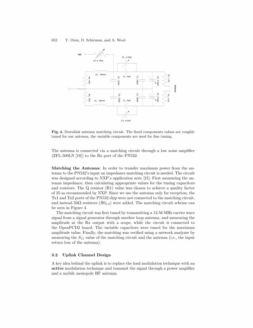
Fig. 4. Downlink antenna matching circuit. The fixed components values are roughlytuned for our antenna, the variable components are used for fine tuning.
The antenna is connected via a matching circuit through a low noise amplifier(ZFL-500LN [18]) to the Rx port of the PN532.
Matching the Antenna: In order to transfer maximum power from the an-tenna to the PN532’s input an impedance matching circuit is needed. The circuitwas designed according to NXP’s application note [21]: First measuring the an-tenna impedance, then calculating appropriate values for the tuning capacitorsand resistors. The Q resistor (R1) value was chosen to achieve a quality factorof 25 as recommended by NXP. Since we use the antenna only for reception, theTx1 and Tx2 ports of the PN532 chip were not connected to the matching circuit,and instead 50Ω resistors (R01,2) were added. The matching circuit scheme canbe seen in Figure 4.The matching circuit was first tuned by transmitting a 13.56 MHz carrier wave
signal from a signal generator through another loop antenna, and measuring theamplitude at the Rx output with a scope, while the circuit is connected tothe OpenPCD2 board. The variable capacitors were tuned for the maximumamplitude value. Finally, the matching was verified using a network analyzer bymeasuring the S11 value of the matching circuit and the antenna (i.e., the inputreturn loss of the antenna).
3.2 Uplink Channel Design
A key idea behind the uplink is to replace the load modulation technique with anactive modulation technique and transmit the signal through a power amplifierand a mobile monopole HF antenna.

Range Extension Attacks on Contactless Smart Cards 653
Carrier
Subcarriers
Sidebands
13.5612.7125 14.4075 f [MHz]
H
Fig. 5. Spectral image of ISO/IEC 14443 communication
Active Load Modulation. is a technique introduced by Finkenzeller et al.in [4,5]. This technique uses active circuitry which produces the same spectralimage as ISO/IEC 14443 type A load modulation, causing the reader to observethe transmitted signal as if it was a standard load modulated signal. Active loadmodulation operates in the following way:As described in Section 2.1 the uplink transmission channel of ISO/IEC 14443-
2 is based on an ASK modulation of a sub-carrier. When looking at the spectralimage of this modulation the result is two sidebands centered at f1,2 = fc± fsc,and each band functions as carrier for the Manchester coded bits (see Figure5). According to [5] a typical ISO/IEC 14443 compliant reader evaluates onlythe upper side band, hence the relevant part of the spectral image is the uppersideband centered at fUSB = fc+fsc = 13.56+
13.5616 = 14.4075MHz. Therefore,
In order to emulate the load modulation signal we can directly modulate theManchester coded bit stream using an ASK 100% modulation of a 14.4075 MHzcarrier signal.Doing so, with an active powered transmitter, allows us to bypass the need for
near-field magnetic coupling, and achieve transmission ranges that are 2 ordersof magnitude greater than the nominal range.
The Transmitting Antenna: Nominal RFID communication is based on mag-netic coupling between two loop antennas. As explained in [5] an effort to increasethe range of an active transmitting signal requires either to dramatically increasethe current injected to the antenna, or to increase the area of the loop (whichalso introduces more noise). An alternative approach is to use the field generatedby an HF monopole antenna. Monopole antennas are designed for electric field(plane wave) transmission rather than magnetic coupling. However, the antennastill produces a magnetic field in the near field region. Moreover, there may bea coupling between the electric field produced by the monopole antenna to thereader’s circuit, which also contributes to the range extension.There are several advantages of using a monopole antenna for this setup.
First, since it usually looks like a simple pole it is easier to hide, which helps

654 Y. Oren, D. Schirman, and A. Wool
in disguising an attack setup. Second, there is a variety of commercial antennasin the ham radio market which are designed for the desired frequency range.And third, we hypothesize that the uplink range will be longer, and the powerconsumption will be reduced in comparison to our 39cm loop antenna.In order to choose the appropriate antenna we conducted a preliminary jam-
ming experiment (see section 4.2). We got the best jamming range with a mili-tary broadband helically wound antenna, NVIS-HF1-BC. The considerations forchoosing the uplink antenna are further described in [23].
Implementation: In order to produce an active load modulation signal fromthe PN532 chip we made use of a little-used output pin named LOAD_MOD.This pin is meant to be connected to an external load, and therefore carries themodulated sub-carrier signal. The OpenPCD2 board does not make use of theLOAD_MOD pin, and the regular libnfc code does not instruct the PN532 toactivate the pin. Thus, we needed to solder a connector directly into the pin andmodify the libnfc code to activate it.For our setup we needed to work with the digital Manchester coded bit stream
rather than the modulated sub-carrier signal. Therefore, we built a simple de-tector circuit consisting of a diode detector and a comparator which extractsthe bit stream from the modulated sub-carrier signal. We used the extracted bitstream to modulate a 14.4075 MHz carrier. Note that for our experiments weproduced the modulated signal by entering the bit stream into a signal genera-tor (Agilent N9310A). The signal generator can be easily replaced by a simplecircuit containing an oscillator and a mixer.Since our signal generator’s output power reaches only up to 15 dBm, we
needed to amplify the signal. We used a Mini-Circuits ZHL-32A [19] amplifierwhich serves as a pre-amplifier, and a RM-Italy KL400 [26] (a ham radio ampli-fier) which serves as a power amplifier. The amplifier output is connected to ouruplink antenna described above.The KL400 amplifier is a mobile amplifier intended to be used in a car mounted
setup. It requires a 12VDC power supply, and when working at full power it usesup to 24A, which can be supplied from a standard car battery.
3.3 Relay Setup
Since our focus was the construction of the ghost system and not the relayitself, we implemented the relay part of the attack inside a single PC. For theleech device we used an unmodified OpenPCD2 board. The ghost antennas areconnected to a second OpenPCD2 board. The OpenPCD2 boards run a libnfccompatible firmware and are both connected to a PC running Linux Fedora 17with libnfc [1].We make use of one of the programs in libnfc, called nfc-relay-picc, which
is a relay application built for boards using the PN532 chip. nfc-relay-picc wasdesigned to overcome the timing issues discussed in Section 2.2, which limit theeffectiveness of relay attacks. The program operates in the following way:

Range Extension Attacks on Contactless Smart Cards 655
– One device is selected as initiator (a leech in our terminology), and the otherdevice is selected as target (a ghost in our terminology).
– The leech is placed in front of a victim tag, emulating a reader. It performsthe initialization and activation protocols defined in the standard, towardsthe tag (further description of these protocols can be found in [13,11]).
– The tag credentials are acquired by the leech and relayed to the ghost device.– The ghost emulates a tag with the data acquired from the original tag andwaits for a reader to activate it.
– When the ghost is activated by the victim reader, it performs the initializa-tion and activation protocols directly with the reader, using the victim tag’scredentials acquired earlier, thus overcoming the very strict delay constraintsof the anticollision level 3 protocol.
– While a transmission protocol is established between the ghost and thereader, a parallel transmission is established between the leech and the tag.
– After both transmission protocols are established, each APDU (level 4) framefrom the reader is relayed through the ghost→PC→leech relay to the tag,and vice versa.
– In order to overcome timing issues during the transmission itself, the ghostsends WTX requests each time the FWT period is about to expire.
Note that in itself the nfc-relay-picc program and the OpenPCD2 boards aredesigned to operate within the nominal range of 5-10cm.To use this program with our uplink setup we had to slightly change the libnfc
source, in order to enable an output of the modulated sub-carrier signal out ofthe LOAD_MOD pin of the PN532 chip.
4 Experiments and Results
In this section we describe the experiments done to test our setup, includingpreliminary experiments to validate our assumptions, and measurements of thefinal setup. All of the experiments described below were done with a TI MFS4100 Reader [9] acting as the victim reader, and a ISO/IEC 14443 type Asample tag which was provided inside the OpenPCD2 package as the victim tag.The MF reader was selected since it generates read requests at a high rate (morethan 10 times per second). In addition, the TI reader’s controller software emitsa loud beep when it receives an answer from the tag.
4.1 Reader-to-Ghost (Downlink) Range Estimation
Our first experiment was to measure the reception range of our downlink coppertube loop antenna in isolation. For this purpose we connected the antenna andthe matching circuit to a simple detector circuit consisting of a diode detectorand a comparator, connected the detector’s output of a scope, and measuredthe received pulses. In order to estimate the reception performance we used thefollowing metric:

656 Y. Oren, D. Schirman, and A. Wool
0.4 0.6 0.8 1 1.2 1.4 1.6 1.80
10
20
30
40
50
60
70
80
90
100
110
range from reader [m]
success rate [%]
Fig. 6. Downlink performance as a function of the distance from the reader
– A reference measurement was taken at a close range, measuring the receptionof few repeated REQA frames.
– For each measurement the number of positive pulses was counted.– For each measurement, we define an error rate metric as the normalizeddifference between the number of pulses in this measurement and in thereference measurement.
Figure 6 present the results of the experiment. We observed good downlinkreception up to a range of 140cm, followed by a dramatic drop in quality withinless than 20 cm. A similar experiment was done using a spectrum analyzerwith an analog output as the detector, and we observed a reception range ofabout 350cm. However, we believe that our detector’s 140cm range predicts theexpected results more accurately, since the ghost’s PN532 chip needs to receivethe messages error-free in order to decode them.Based on [25] we believe that a greater downlink range may well be possible.
However, we must note that the ghost range is bounded by both the uplink andthe downlink ranges.
4.2 Ghost-to-Reader (Uplink) Range Estimation
An isolated estimation of the uplink performance was a more challenging task,since transmission from the tag to the reader occurs only after a successful recep-tion of a reader’s frame by the tag (i.e., a working downlink channel is required).Hence, in order to test the performance of the RF part of the uplink channel(signal generator, amplifier, and antenna) we conducted a jamming experiment.The basic principle of the jamming setup is to use the same setup as the uplinkchannel, only without modulation, in order to transmit a continuous wave signalat the upper side band frequency (14.4075 MHz, recall Figure 5). By transmit-ting a powerful signal towards the reader at the same frequency as the tag’stransmission, we block the tag’s response and jam the communication betweenthe reader and the tag.
Range Extension Attacks on Contactless Smart Cards 657
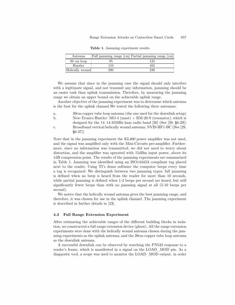
Table 1. Jamming experiment results
Antenna Full jamming range [cm] Partial jamming range [cm]
39 cm loop 95 125
Hustler 110 165
Helically wound 200 230
We assume that since in the jamming case the signal should only interferewith a legitimate signal, and not transmit any information, jamming should bean easier task than uplink transmission. Therefore, by measuring the jammingrange we obtain an upper bound on the achievable uplink range.Another objective of the jamming experiment was to determine which antenna
is the best for the uplink channel.We tested the following three antennas:
a. 39cm copper tube loop antenna (the one used for the downlink setup)b. New-Tronics Hustler: MO-4 (mast) + RM-20-S (resonator), which is
designed for the 14–14.35MHz ham radio band [20] (See [29, §6-29])c. Broadband vertical helically wound antenna: NVIS-HF1-BC (See [29,
§6-37])
Note that in the jamming experiment the KL400 power amplifier was not used,and the signal was amplified only with the Mini-Circuits pre-amplifier. Further-more, since no information was transmitted, we did not need to worry aboutdistortion, and the amplifier was operated with 15dBm input power, above its1dB compression point. The results of the jamming experiments are summarizedin Table 1. Jamming was identified using an ISO14443A compliant tag placednext to the reader. Using TI’s demo software the computer beeps every timea tag is recognized. We distinguish between two jamming types: full jammingis defined when no beep is heard from the reader for more than 10 seconds,while partial jamming is defined when 1-2 beeps per second are heard, but stillsignificantly fewer beeps than with no jamming signal at all (5-10 beeps persecond).We notice that the helically wound antenna gives the best jamming range, and
therefore, it was chosen for use in the uplink channel. The jamming experimentis described in further details in [23].
4.3 Full Range Extension Experiment
After estimating the achievable ranges of the different building blocks in isola-tion, we constructed a full range extension device (ghost). All the range extensionexperiments were done with the helically wound antenna chosen during the jam-ming experiments as the uplink antenna, and the 39cm copper tube loop antennaas the downlink antenna.A successful downlink can be observed by watching the PN532 response to a
reader’s frame, which is manifested in a signal on the LOAD_MOD pin. As adiagnostic tool, a scope was used to monitor the LOAD_MOD output, in order

658 Y. Oren, D. Schirman, and A. Wool
to identify a successful downlink. The measured downlink range is 120cm – twoorders of magnitude greater than the nominal range, and enough in many casesfor an attacker to move far enough from the victim reader to avoid capture.On the other hand, uplink measurements were more complex, since the uplink
channel was found to be very sensitive to the surrounding environment and cableorientation. A successful uplink was identified by hearing the TI reader’s demosoftware beep for a successful read of a tag. So, a successful uplink also meant asuccessful range extended relay. Our first attempts with measuring uplink rangesproduced suspiciously high ranges. We discovered that the high range was dueto an unwanted coupling effect as noticed by [30]. In our initial setup a coaxialcable was passing between the uplink setup and the reader (not connected toany of them), serving as a waveguide for the uplink signal.We then decided to move our setup outside of the building in order to work in
a clear and robust environment. The first measurements were held with only theMini-Circuit’s 25dB pre-amplifier which has an output-1dB-compression-point of29dBm (~800mW). In practice, we noticed that at output levels of above 25dBm(~300 mW) the performance of the uplink channel was severely degraded. Webelieve that this is the result of noise created by operating the amplifier close toits compression point. Therefore, all the measurements were done using a 0dBmpower at the output of the signal generator.At first, the experiment was held with the monopole antenna alone, and we
achieved only a 35cm uplink range. We believe that this is due to the fact thatmonopole antennas need to be placed over a proper ground plane for optimalperformance. Since the wave length of our uplink signal is ~20m a true groundplane is impractical. Instead, we assumed a car mounted setup, in which the caritself can serve as a ground plane. To emulate a private car’s dimensions we useda 1m2 tin plate as a ground plane. With the antenna bolted onto the tin plateand using only the pre-amplifier we managed to get an uplink range of 85cm.We noticed that this setup is very sensitive to the orientation of the antennacable regarding the tin plate – with different cable orientations the maximaluplink range varied between 45cm to 85cm. We further noticed that the bestuplink ranges were achieved when the antenna was facing the side of the victimreader and not its front. A possible explanation is that when the uplink antennawas placed in front of the reader, it was jamming the downlink antenna fromreceiving the reader’s signal, and therefore preventing a full relay.At last, after establishing a good setup for the uplink antenna, we added the
power amplifier into the transmission chain. Since our pre-amplifier can onlyproduce up to 300mW without distorting the signal, yet the RM-Italy KL400amplifier’s input power must be at least 1W, we had to bypass an internal relayinside the amplifier’s circuit in order to let the amplifier open for transmissionwith lower input power. During our experiments we set the KL400 only up to its2nd power level (out of 6 possible levels) due to radiation hazard concerns (bothfor the equipment, and for our safety). Later we measured the output power ofthe modified KL400 amplifier set to its 2nd level and found out the output powerof our system was about 7W.

Range Extension Attacks on Contactless Smart Cards 659
Table 2. Range extension results
Antenna setup Amplifier Full bidirectional range [cm]
no ground plane pre-amplifier (Pout = 300mW ) 35
1m2ground plane pre-amplifier (Pout = 300mW ) 85
1m2ground plane pre-amplifier + power amplifier (Pout = 7W ) 115
After all modifications, the measured uplink range including the power am-plifier was 115cm, which is almost the same as our measured downlink range,and again enough for an adversary to mount his attack from the next room. Theresults of the different uplink setups are summarized in Table 2. The final setupincluding the tin plate and the power amplifier can be seen in Figure 7.
Fig. 7. The full range extension setup outside our building. The victim reader is locatedon the lab stool in the middle of the picture. The uplink antenna on its ground planeis on the left. The downlink loop antenna is behind the reader. The victim tag is onthe table in the back, next to the laptop running the relay software.
5 Discussion and Conclusions
The range extension setup described in this work has significant implications onthe security of close range RFID systems. The same setup can also be used forlegitimate purposes, in order to enhance RFID capabilities. In this section webriefly introduce two attack scenarios and some legitimate use examples for thissetup.

660 Y. Oren, D. Schirman, and A. Wool
5.1 Attack Scenarios
E-voting. The work of [24] presents a set of physical attacks on Israel’s proposede-voting system which uses ISO/IEC 14443 tags as voting ballots. Using a relaysetup an attacker can mount a ballot sniffing attack (which allows him tolearn at any time which votes were already cast into the ballot box), a singledissident attack (which can undetectably suppress the votes for any amountof voters), and finally a ballot stuffing attack (which gives the adversarycomplete control over previously cast votes).Using a nominal-range relay the attacks mentioned in [24] are limited since the
adversary must be in a range of 5-10 cm from the target ballots, which places himinside the ballot station’s room, and in front of the election committee members.However, if the relay setup is enhanced with a range extension setup the attackscan be mounted from a distance, possibly even from outside the room, whichallows the attacker to mount the attack without being detected.
Access Control. One of the most common application of close range RFID isfor access control into restricted areas. Using personal RFID tags only authorizedpersonnel can enter a restricted area.Using a relay setup an adversary can use a victim worker’s identity while he
is away from the restricted door, and the tag lies in his pocket, to open the door.However, using a nominal relay setup, this attack scenario is limited, since whenthe attacker approaches the door holding his ghost device instead of a regular taghe can be easily spotted by the other workers who walk by. Alternatively, if theattacker mounts a range extension setup in a distance from the door (possiblyeven behind a wall), he can cause the door to open while an accomplice walkstowards the door and waves a decoy blank tag in front of the reader. Since theaccomplice does not carry any special hardware other than a decoy tag, the riskincurred by the attacker is drastically lowered.An interesting twist on this attack would be combination of an RFID zapper
[27] and an extended-range ghost. An RFID zapper is a low-cost device whichcan completely disable a victim tag by applying a high-energy electromagneticpulse to its RF input. If an attacker first zaps a victim’s tag, then applies anextended-range ghost attack to the reader just as the victim attempts to use his(now disabled) tag, it will give any human observers the impression that one tagis used, while effectively activating a different tag. This forces an innocent userto be an accomplice to the relay attack described above.
5.2 Legitimate Uses for Range Extension
Besides breaking the close range assumption, and violating the system’s security,the range extension setup can be used for legitimate purposes.For example, a handicapped person sitting in a wheel chair might find it hard
to use RFID tags, since most of the readers are placed out of his reach. Bymounting a range extension setup onto the wheel chair, the user will now find

Range Extension Attacks on Contactless Smart Cards 661
it possible to enter through doors with RFID access control, or pay for publictransportation without asking for help.As another example, nowadays many parking lots have RFID tags for sub-
scribers. Many drivers find it hard to reach the RFID reader through the car’swindow. By mounting a range extension setup onto his car, the driver can enterinto the parking lot without the effort of reaching the reader at the entrance ofthe parking lot.
5.3 Conclusions
In this work we presented a range extension setup for contactless smart cards.The setup can be mounted on any car, and powered by a regular car battery.The entire setup costs about $2,000. The uplink antenna constitutes most of thesum, and can be replaced by a cheaper model for cost reduction.Using this setup the close range assumption of ISO/IEC 14443 applications is
broken, since the tag does not have to be placed 5-10cm from the reader, but canbe at a distance of over 1m. Moreover, the more severe implication of this attackis in combination with the known relay attack. While one of the drawbacks ofa regular relay attack is that the attacker can be seen operating a device rightnext to the reader or the tag, using our range extended ghost together with arange extended leech presented at [16] the attacker can conceal his devices, andin the case of the range extended ghost might even place his device in the nextroom.The attacks mentioned above operate at the physical layer of the standard,
and therefore, are difficult to defend against by a protocol based solution. De-signers of close range RFID applications like: credit cards, e-passports, accesscontrol, and e-voting should take into consideration the threats introduced byextending the nominal operation range of ISO/IEC 14443 tags.
References
1. libnfc website (2013), http://nfc-tools.org/index.php?title=Main_Page
2. APACS. APACS response to BBC watchdog and chip and PIN. Press realese(February 2007),http://www.chipandpin.co.uk/media/documents/
APACSresponsetoWatchdogandchipandPIN-06.02.07.pdf
3. Desmedt, Y., Goutier, C., Bengio, S.: Special uses and abuses of the Fiat-Shamirpassport protocol. In: Pomerance, C. (ed.) CRYPTO 1987. LNCS, vol. 293, pp.21–39. Springer, Heidelberg (1988)
4. Finkenzeller, K.: Battery powered tags for ISO/IEC 14443, actively emulating loadmodulation. In: 7th European Workshop on Smart Objects: Systems, Technologiesand Applications (RFID SysTech) (May 2011)
5. Finkenzeller, K., Pfeiffer, F., Biebl, E.: Range Extension of an ISO/IEC 14443type A RFID System with Actively Emulating Load Modulation. In: 7th Euro-pean Workshop on Smart Objects: Systems, Technologies and Applications (RFIDSysTech) (May 2011)

662 Y. Oren, D. Schirman, and A. Wool
6. Francis, L., Hancke, G., Mayes, K., Markantonakis, K.: Practical NFC peer-to-peerrelay attack using mobile phones. In: Ors Yalcin, S.B. (ed.) RFIDSec 2010. LNCS,vol. 6370, pp. 35–49. Springer, Heidelberg (2010)
7. Hancke, G.P.: Practical attacks on proximity identification systems (short paper).In: SP 2006: Proceedings of the 2006 IEEE Symposium on Security and Privacy,Oakland, CA, pp. 328–333. IEEE Computer Society (2006)
8. Hancke, G.P.: Practical eavesdropping and skimming attacks on high-frequencyRFID tokens. Journal of Computer Security 19(2), 259–288 (2011)
9. Texas Instruments. Multi function reader series 4000 (March 2005),http://www.ti.com/rfid/docs/manuals/pdfSpecs/RF-MFR-RNLK-00.pdf
10. International Organization for Standardization, Geneva. ISO/IEC 14443-1 Identi-fication cards – Contactless integrated circuit cards – Proximity cards – Part 1:Physical characteristics (2008)
11. International Organization for Standardization, Geneva. ISO/IEC 14443-4 Identi-fication cards – Contactless integrated circuit cards – Proximity cards – Part 4:Transmission protocol (2008)
12. International Organization for Standardization, Geneva. ISO/IEC 14443-2 Identi-fication cards – Contactless integrated circuit cards – Proximity cards – Part 2:Radio frequency power and signal interface (2010)
13. International Organization for Standardization, Geneva. ISO/IEC 14443-3 Identi-fication cards – Contactless integrated circuit cards – Proximity cards – Part 3:Initialization and anticollision (2011)
14. Issovits, W., Hutter, M.: Weaknesses of the ISO/IEC 14443 protocol regardingrelay attacks. In: 2011 IEEE International Conference on RFID-Technologies andApplications (RFID-TA), pp. 335–342. IEEE (2011)
15. Kfir, Z., Wool, A.: Picking virtual pockets using relay attacks on contactless smart-cards. In: International Conference on Security and Privacy for Emerging Areas inCommunications Networks, Los Alamitos, CA, USA, pp. 47–58. IEEE ComputerSociety (2005)
16. Kirschenbaum, I., Wool, A.: How to build a low-cost, extended-range RFID skim-mer. In: Proceedings of the 15th USENIX Security Symposium, Vancouver, B.C.,Canada. USENIX Association (2006)
17. Bit Manufaktur. OpenPCD2 (2012),http://www.openpcd.org/OpenPCD_2_RFID_Reader_for_13.56MHz
18. Mini-Circuits. ZFL-500LN low noise amplifier,http://www.minicircuits.com/pdfs/ZFL-500LN.pdf
19. Mini-Circuits. ZHL-32A coaxial amplifier (August 2009),http://www.minicircuits.com/pdfs/ZHL-32A.pdf
20. New-Tronics. mobile HF hustler antenna (October 2008),http://www.new-tronics.com/main/html/mobile__hf.html
21. NXP. AN1425 - RF Amplifier for NXP Contactless NFC Reader ICs (August 2011),http://www.nxp.com/download/grouping/10529/application_note
22. NXP. PN532 - Near Field Communication (NFC) controller (September 2012),http://www.nxp.com/documents/short_data_sheet/PN532_C1_SDS.pdf
23. Oren, Y., Schirman, D., Wool, A.: RFID jamming and attacks on Israeli e-voting.In: ITG-Fachbericht-Smart SysTech 2012 (2012)
24. Oren, Y., Wool, A.: RFID-Based electronic voting: What could possibly go wrong?In: International IEEE Conference on RFID, Orlando, USA, pp. 118–125 (2010)
25. Pfeiffer, F., Finkenzeller, K., Biebl, E.: Theoretical limits of ISO/IEC 14443 typeA RFID eavesdropping attacks. In: ITG-Fachbericht-Smart SysTech 2010 (2012)

Range Extension Attacks on Contactless Smart Cards 663
26. RM-Italy. KL400 Linear Amplifier (2005),http://www.rmitaly.com/scheda.asp?IDGr=1&cat=0&tipo=96
27. Runge, T.: Schriftliche arbeit jugend forscht: Der RFID-Zapper (February 2007)(in German), http://rfidzapper.dyndns.org/RFID-ZAPPER.pdf
28. Sportiello, L., Ciardulli, A.: Long distance relay attack. RFIDSec (July 2013)29. Straw, R.D.: The ARRL antenna book: The Ultimate Reference for Amateur Radio
Antennas. Amer Radio Relay League (2003)30. Thevenon, P.-H., Savry, O., Tedjini, S., Malherbi-Martins, R.: Attacks on the HF
physical layer of contactless and RFID systems. In: Current Trends and Challengesin RFID (2011)