rampmaster® ii - evenheat kiln, inc. · pdf filerampmaster ii board temperature ... the...
TRANSCRIPT
RampMaster II Operating Manual
RMII – Aug. 2015
Page 1 of 26 Use your Smart-phone to scan this QR code to watch RampMaster II how-to Programming Videos!
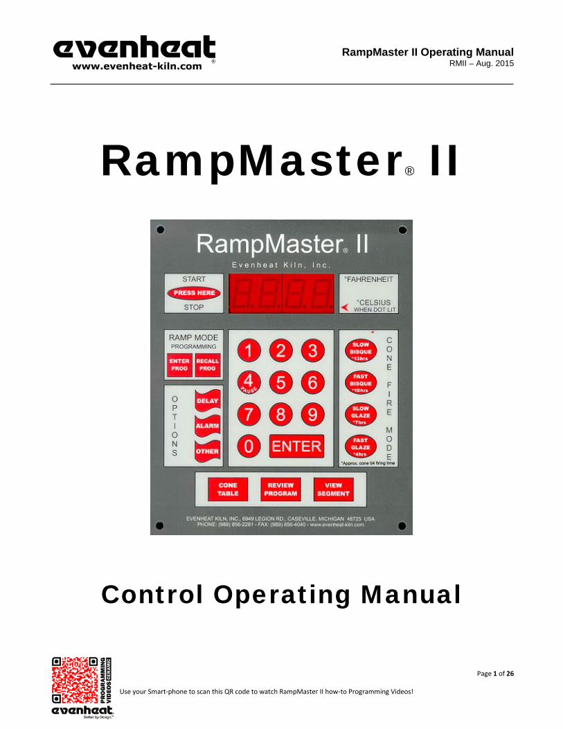
RampMaster® II
Control Operating Manual

RampMaster II Operating Manual
RMII – Aug. 2015
Page 2 of 26 Use your Smart-phone to scan this QR code to watch RampMaster II how-to Programming Videos!
Thank you for purchasing a RampMaster II equipped kiln from Evenheat. The RampMaster II control is designed to offer a full featured control in an easy to use design. The RampMaster II offers two, distinct programming modes that allow you to create your own custom firings or use pre-loaded cone calculated ceramic firing data. You’ll also find a host of “On-the-Fly” features that give you complete control of the firing process. Please take some time to read this manual. Not only does it cover the basics, it also contains some little gems that are sure to make your command of the RampMaster II a thoroughly rewarding experience. CAUTION: The RampMaster II is used to control temperature, it is not a safety devise. Never leave the kiln unattended while firing. Check on the kiln at the end of the firing to ensure firing program has completed as planned. CAUTION: Throw control power switch, located on kiln control panel, to the OFF position (O) when not in use.
Table of Contents Quick Cone Fire Mode Programming .................................... 3 Quick Ramp Mode Programming .......................................... 4 RampMaster II Key Layout .................................................... 5 RampMaster II Key Descriptions ........................................... 6 Detailed Cone Fire Mode Programming ................................ 7 Detailed Ramp Mode Programming ...................................... 8 Viewing Current Segment Data ............................................. 9 Skip to Next Segment .......................................................... 10 Alarm................................................................................... 10 Adding Time to a Hold ......................................................... 10 Suspend............................................................................... 10 Initialization (Boot Up) ........................................................ 11 Storing a Ramp Mode Program ........................................... 11 Recalling a Ramp Mode Program ........................................ 11 Programming a Rate............................................................ 11 Programming a Time ........................................................... 11 6 Ramp Mode Programs...................................................... 11 8 Segments per Program ..................................................... 11 Two Key Start ...................................................................... 11 Reviewing Your Program Before Starting ............................ 12 Delay Start ........................................................................... 12 Writing Over Previously Stored Data................................... 12 Idle (IdLE) ............................................................................ 12
Controlled Cool Down ......................................................... 12 Firing Counter ..................................................................... 12 Maximum Programmable Temperature ............................. 12 Zone Control ....................................................................... 13 Cone Table .......................................................................... 13 Reset Thermocouple Offset & Error Codes ......................... 13 Pre-heat Feature ................................................................. 14 ID for Computer Use ........................................................... 14 16 Segment Programs ......................................................... 14 Cone Offset ......................................................................... 15 Change Temperature Scale (°F or °C) .................................. 16 Error Code Enable/Disable .................................................. 16 Thermocouple Offset .......................................................... 16 Percent 4............................................................................. 17 RampMaster II Board Temperature .................................... 17 RampMaster II Display Conditions ...................................... 18 RampMaster II Display Messages ....................................... 19 Key Function Table.............................................................. 20 Preset Cone Fire Mode Firing Data Table............................ 23 Cone Table .......................................................................... 24 RampMaster II Error Messages ........................................... 24 Kiln Trouble Shooting .......................................................... 25

RampMaster II Operating Manual
RMII – Aug. 2015
Page 3 of 26 Use your Smart-phone to scan this QR code to watch RampMaster II how-to Programming Videos!
Use this Quick Guide to immediately begin programming your ceramic firing using the Cone Fire Mode.
Cone Fire Mode is designed for use with ceramic firing only. Please use the Ramp Mode to fire all other materials.
The Cone Fire Mode of programming allows you to fire ceramics by choosing the desired total firing time and the cone number you would like to fire to. With these simple questions the RampMaster II calculates the firing parameters and fires your ware accordingly. Many artists will find the Cone Fire mode to offer everything they need in a firing. However, if you would like absolute control over all of the firing parameters we suggest using the Ramp Mode Programming to create a custom firing program. Quick Steps when using the Cone Fire Mode Programming 1. Throw the power switch on the kiln control panel to the On position 2. The RampMaster II begins its initiation process and the display will illuminate. 3. The RampMaster II will finish the initiation process and then display IdLE along with chamber temperature. 4. Press one of the Cone Fire Mode keys based on your desired total firing time. Times are approximate. 5. Press the Enter key. CONE is displayed along with the previously chosen cone number. 6. Use the numerical keys to choose your cone number. Please be careful when choosing. For example, an 06 cone must be entered as “0” “6”. If you fail to key in the “0” you will have chosen cone 6 which is a hotter cone number. 7. Press the Enter key. HOLd is displayed along with the previous hold time. A hold time will hold or maintain your final temperature for the period of time you desire. Set to 0.00 for normal operation. 8. Use the numerical keys to choose your hold time in hours and minutes. 9. Press the Enter key. RA 8 is displayed along with the previous rate used on Segment 8. This setting allows you to control the final cooling segment of the firing. If you would like something slower than a natural cool at the end of the firing, this is where you would control that. Set to 0 for natural cool. 10. Use the numerical keys to choose rate on Segment 8. 11. Press the Enter key. 12. The display will read IdLE. 13. Press the Start/Stop key and then press the Enter key. 14. –ON- is displayed and the RampMaster II is now running your program.

RampMaster II Operating Manual
RMII – Aug. 2015
Page 4 of 26 Use your Smart-phone to scan this QR code to watch RampMaster II how-to Programming Videos!
Use this Quick Guide to immediately begin programming using the Ramp Mode Programming Process.
The Ramp Mode allows the creation of your own custom firing program. You choose the rate of temperature increase or decrease, the temperature you want to achieve and any hold time once you’re there. These 3 items, taken together, create what’s known as a segment. Segments are basically chained together to create a multi-segment program. Materials to be fired are generally supplied with appropriate firing data. If you do not have this data contact your materials supplier. Quick Steps when using the Ramp Mode Programming 1. Throw the power switch on the kiln control panel to the On position. 2. The RampMaster II begins its initiation process and the display will illuminate. 3. The RampMaster II will finish the initiation process and then display IdLE along with chamber temperature. 4. Press the Enter Prog key one time. USER is displayed along with some number. 5. Use the Numerical keys to choose. You’re choosing which of the 6 user programs to use. Your choices are 1 thru 6. 6. Press the Enter key. SEGS is displayed along with some number. 7. Use the Numerical keys to choose. You’re choosing number of segments in the program. Your choices are 1 thru 8. 8. Press the Enter key. RA 1 is displayed along with some number. 9. Use the Numerical keys to choose. You’re programming the temperature rate (°/hr.) for this segment. 10. Press the Enter key. °F 1 is displayed along with some number. 11. Use the Numerical keys to choose. You’re programming the temperature set point for this segment. 12. Press the Enter key. HLd is displayed along with some number. 13. Use the Numerical keys to choose. You’re programming the hold time for this segment. 14. Press the Enter key. RA 2 is displayed. Repeat steps 9 thru 14 for all remaining segments until the display reads ALRM. 15. Use the Numerical keys to choose alarm temperature. Choosing 9999 turns the alarm feature off. 16. Press the Enter key. The display will read CPL, then IdLE along with current chamber temperature. 17. Press the Start/Stop key and then press the Enter key. 18. –ON- is displayed and the RampMaster II is now running your program.
RampMaster II Operating Manual
RMII – Aug. 2015
Page 5 of 26 Use your Smart-phone to scan this QR code to watch RampMaster II how-to Programming Videos!
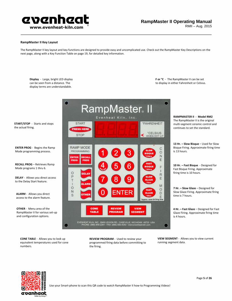
RampMaster II Key Layout The RampMaster II key layout and key functions are designed to provide easy and uncomplicated use. Check out the RampMaster Key Descriptions on the next page, along with a Key Function Table on page 19, for detailed key information.
Display - Large, bright LED display can be seen from a distance. The display terms are understandable.
START/STOP - Starts and stops the actual firing.
ENTER PROG - Begins the Ramp Mode programming process.
RECALL PROG – Retrieves Ramp Mode programs 1 thru 6.
DELAY - Allows you direct access to the Delay Start feature.
ALARM - Allows you direct access to the alarm feature.
OTHER - Menu area of the RampMaster II for various set-up and configuration options.
CONE TABLE - Allows you to look up equivalent temperatures used for cone numbers.
F or °C - The RampMaster II can be set to display in either Fahrenheit or Celsius.
RAMPMASTER II - Model RM2 The RampMaster II is the original multi-segment ceramic control and continues to set the standard.
13 Hr. – Slow Bisque – Used for Slow Bisque Firing. Approximate firing time is 13 hours.
10 Hr. – Fast Bisque - Designed for Fast Bisque Firing. Approximate firing time is 10 hours.
7 Hr. – Slow Glaze – Designed for Slow Glaze Firing. Approximate firing time is 7 hours.
4 Hr. – Fast Glaze – Designed for Fast Glaze Firing. Approximate firing time is 4 hours.
VIEW SEGMENT - Allows you to view current running segment data.
REVIEW PROGRAM - Used to review your programmed firing data before committing to the firing.
RampMaster II Operating Manual
RMII – Aug. 2015
Page 6 of 26 Use your Smart-phone to scan this QR code to watch RampMaster II how-to Programming Videos!
RampMaster II Key Descriptions START/STOP The Start/Stop key starts and stops the firing process. ENTER PROG The Enter Prog key is used to begin the Ramp Mode Programming Process. RECALL PROG The Recall Prog key allows the user to recall or bring up a previously programmed Ramp Mode Program for firing. DELAY The Delay key is used to set a delay start time. ALARM The Alarm key provides direct access to the Alarm feature. OTHER The Other key is used to access the menu area of the RampMaster II. This menu area contains various set-up and configurations options that allow you to tailor the RampMaster II to your needs. 13 Hr.—SLOW BISQUE Pre-set Cone Fire Mode choice. Provides an extended, multi-segment program specifically designed for a slow green firing. Firing time is approximate. 10 Hr.—FAST BISQUE Pre-set Cone Fire Mode choice. Provides a multi-segment program specifically designed for a general green firing. Firing time is approximate. 7 Hr.—SLOW GLAZE Pre-set Cone Fire Mode choice. Provides an extended, multi-segment program specifically designed for a slow glaze firing. Firing time is approximate. 4 Hr.—FAST GLAZE Pre-set Cone Fire Mode choice. Provides a multi-segment program specifically designed for a slow, green firing. Firing time is approximate. CONE TABLE Cone look-up table. The look-up table displays the equivalent temperature pre-set for each cone value. Default pre-set values based on the 108°F chart. REVIEW PROGRAM Allows the artist to review the programmed data before running the program. VIEW SEGMENT Used during firing, the View Segment key displays firing data for the currently running segment. NUMERICAL KEYS The Numerical Keys are used to key-in specific data. ENTER The Enter key is used to store displayed data. During programming, the Enter key stores the displayed data and moves the programming to the next step.

RampMaster II Operating Manual
RMII – Aug. 2015
Page 7 of 26 Use your Smart-phone to scan this QR code to watch RampMaster II how-to Programming Videos!
Cone Fire Mode Programming The Cone Fire Mode is used exclusively for ceramic firing. The Cone Fire method of programming uses pre-loaded firing data developed specifically for ceramic firing. The RampMaster II simply asks for the desired firing time and cone number. Once this information is keyed in, the control automatically fires your ware accordingly. The Cone Fire Mode offers the artist a very simple and straight forward approach to programming. It performs remarkably well in most situations. For the dedicated artist, however, it can be somewhat limiting. For these artists, the RampMaster II does contain a programming method called Ramp Mode Programming. The Ramp Mode method allows for the creation of custom firing programs. Cone Fire Mode Programming Beginning the Cone Fire Mode programming process is simple: select one of the four, pre-set Cone Fire Mode keys located on the right side of the RampMaster II.
4 Hr. — Fast Glaze Firing — The 4 hour, Fast Glaze firing is a very simple, 2 segment program. It’s relatively quick at 570°/hr. We recommend using this program for glaze firings only. You may view a copy of this program’s firing data on page 22 of this manual. 7 Hr. — Slow Glaze Firing — The 7 hour, Slow Glaze firing slows down the glaze firing to a rate of 400°/hr. Many artists also use this program for their bisque firings. It’s relatively fast compared to the other bisque programs and provides excellent results, particularly on slip cast. You may view a copy of this program’s firing data on page 22 of this manual. 10 Hr. — Fast Bisque Firing — The 10 hour, fast bisque firing is a fairly standard and traditional bisque firing program. You may view a copy of this program’s firing data on page 22 of this manual. 13 Hr. — Slow Bisque Firing — The 13 hour, slow bisque firing is a very conservative bisque firing program. You may view a copy of this program’s firing data on page 22 of this manual.
1. With the display reading IdLE (Idle) simply press one of the four Cone Fire Mode keys one time. The approximate firing time will be displayed. 2. Press the Enter key. CONE is displayed along with the previously selected cone number. 3. Use the Numerical keys to choose the cone number you desire, being careful to properly enter the correct cone number. If your cone number begins with a 0 then you must use the 0 when programming.
Be careful here, cone numbers use an interesting numbering method which can cause confusion when programming. As an example compare cone 06 with cone 6. Cone 06 uses an equivalent temperature of 1828°F while a cone 6 uses an equivalent temperature of 2232°F. If you want a cone 06 but program in a cone 6 you’ll get a severe overfire. This is important as Evenheat does not cover damage caused by overfire regardless of the reason.
4. Press the Enter key. HOLd is displayed along with the previously used hold time.
The RampMaster II is asking if you would like to hold the final temperature for any period of time. Do you have to? No. Most artists leave it set to 0.00. However, if you find that your ware is slightly underfiring adding a small amount of hold time will extend the firing and bring your underfiring ware to perfect maturity. If you do add a hold time, start small with 1 or 2 minutes and follow your results from there.
5. Use the numerical keys to select your hold and press the Enter key. RA 8 is displayed along with the previously used rate value for segment 8.
The RampMaster II is asking you if you would like to control the cooling process. The preset programs control the temperature up to cone number. After that the kiln is allowed to cool naturally. For most artists the natural cooling is slow enough. For others they like to slow it down.
6. Use the Numerical keys to choose your cooling rate. For natural cooling use 0. The display will read IdLE. Programming is complete. 7. To run the Cone Fire Mode program press the Start/Stop key one time. The display shows 4 lines. Press the Enter key. The display will read –ON– followed by the current chamber temperature. You may STOP the firing at any time by pressing the Start/Stop key. When the firing is complete the display alternates between CPLT, current chamber temperature and total firing time. Pressing the Start/Stop key at this point will return the display to the IdLE (Idle) position.
RampMaster II Operating Manual
RMII – Aug. 2015
Page 8 of 26 Use your Smart-phone to scan this QR code to watch RampMaster II how-to Programming Videos!
Ramp Mode Programming The Ramp Mode is a method of programming that allows you, the artist, to precisely define every aspect of the firing. You’re creating a custom firing program, designed for the work at hand. It’s a very rewarding experience. Creating a custom program is not difficult. It does however require some knowledge and forethought about what you want to do and how to go about it. Imparting that knowledge is beyond the scope of this manual. Consult with your materials supplier for specific firing data. First Things First: Segments—What are They? Most firing programs require the kiln to go to multiple temperatures and to use multiple heating rates throughout the firing. In order for the RampMaster II to perform all these changes, it breaks the entire program down into smaller chunks called “Segments”. Your program will consist of many segments, chained together, one after another, to create the finished program. During firing, the RampMaster II works from one segment to the next until all segments have been run. The RampMaster II needs to know three things at any point during the firing: How fast am I supposed to get to temperature? What temperature am I going to? And, once I’m there, should I stay there for any amount of time? These three things combine to make one segment. Once you understand this concept that a segment includes a rate of temperature change, a particular temperature you want to reach and a hold at the temperature, you’ve got it. Now we can show you how to program! Ramp Mode Programming 1. With the display reading IdLE (Idle) simply press the Enter Prog key one time. USER is displayed along with the previously used user program number.
The RampMaster II is asking which of the 6 available locations you would like to store your program. In other words: a program number. You’re choices are 1 thru 6. Use the numerical keys to choose.
2. Press the Enter key. SEGS is displayed along with the some number.
The RampMaster II wants to know the total number of segments you would like to use for the program. You can use up to 8 segments for your program. Your choices are 1 thru 8. Use the numerical keys to choose and press the Enter key. It’s also possible to program up to 16 segments using a special feature found on page 14 of this manual.
3. Press the Enter key. RA 1 is displayed.
RA stands for Rate and the 1 means you’re programming the rate for segment 1. Rate means speed and you need to tell the RampMaster II how fast you want the temperature to increase. You can also tell the RampMaster II how fast you want the temperature to decrease, but not in segment 1, that wouldn’t make sense! Rate for the RampMaster II is programmed in degrees per hour (°/hr.). The choice is yours. Use the numerical keys put in your rate.
4. Press the Enter key. °F 1 is displayed.
°F stands for the temperature setpoint (°C is displayed if you’re using Celsius) and the 1 means you’re programming the temperature you would like to reach in segment 1. The choice is yours. Use the numerical keys to put in your temperature.
5. Press the Enter key. HLD1 is displayed.
HLD stands for Hold (a.k.a. soak or dwell) and the 1 means you’re programming the amount of time you want the temperature to stay at the segment 1 temperature once you reach it. Hold time is programmed in hours and minutes. You do not have to hold at temperature if you don’t want to, in which case hold time would be 0. Use the numerical keys to put in your hold time.
6. Press the Enter key. RA 2 is displayed.
The RampMaster II is now asking for the rate of temperature increase or decrease in segment 2. Simply key in the rate you want to use for segment 2.
7. Press the Enter key. °F 2 is displayed.
The RampMaster II is now asking for the temperature setpoint to use on segment 2. Simply key in the temperature.

RampMaster II Operating Manual
RMII – Aug. 2015
Page 9 of 26 Use your Smart-phone to scan this QR code to watch RampMaster II how-to Programming Videos!
Ramp Mode Programming Continued from Previous Page 8. Press the Enter key. HLD2 is displayed.
The RampMaster II is now asking for the amount of time you want to hold at your segment 2 temperature. Simply key in the amount of desired hold time.
9. Press the Enter key. As you can see from the emerging pattern, the RampMaster II will continue to ask the same three questions: rate, temp and time for all remaining segments. Just keep answering the questions. Doing so creates that beautiful chain of events called a firing program! Once all your segments are programmed the RampMaster II will display ALRM which stands for Alarm. The Alarm feature allows you to set a temperature at which the alarm sounds. It could be any temperature you want. To disable the alarm, key in 9999 and press the Enter key. CPL is displayed briefly followed by IdLE. Programming is complete! Your firing data is now stored in the User program you’ve selected and is ready to go. To run the program, press the Start/Stop key one time. Four dashes will appear. Press the Enter key. The display will read –ON– followed by the current chamber temperature. The RampMaster II is now running your Ramp Mode program. You may STOP the firing at any time by pressing the Start/Stop key. When the firing is complete the display alternates between CPLT, current chamber temperature and total firing time. Pressing the Start/Stop key at this point will return the display to the IdLE (Idle) position. On-the-Fly Features The RampMaster II contains a set of features that allow you to adjust and tweak the firing while it’s actually running! We’ve dubbed these as “On-the-Fly”. With these features it’s possible to view the currently running segment data, adjust alarms and even skip ahead into the next available segment. Knowing that these features are available, and using them, will positively affect your firing skills and allow you to create the pieces you want to create. Viewing Current Segment Data When firing, the RampMaster II displays current temperatures and times, it does not display your program settings. Doing so would overwhelm and confuse, and we don’t want to do that. However, this information is nice to know when you want to know it. The View Segment key allows for this.
Using the VIEW SEGMENT Feature During the Ramping Portion of the Segment Press the View Segment key one time. Programmed rate is displayed for the current segment along with the current traveling set point (traveling set point is the temperature the control wants to be at, at that particular moment). Actual temperature of the electronics is also displayed (bd T). Using the VIEW SEGMENT Feature During the Holding Portion of the Segment Press the View Segment key one time. Programmed hold time is displayed for the current segment. The Hold temperature is also displayed along with the actual temperature of the electronics (bd T).
RampMaster II Operating Manual
RMII – Aug. 2015
Page 10 of 26 Use your Smart-phone to scan this QR code to watch RampMaster II how-to Programming Videos!
On-the-Fly Features Continued from Previous Page Skip to Next Segment The RampMaster II allows you to move to the next available firing segment without having to complete the currently running segment. It’s used when enough heat-work has been achieved at the current segment and you want to immediately move to the next portion of the firing program. This feature comes in handy with glass related firing when moving to the anneal portion of the program is necessary. The Skip Ahead feature is only available when running a Ramp Mode Program. It is not available during a Cone Fire Mode Program.
To Use the Skip Segment Feature Press the View Segment key and then press the Enter key within 2 seconds. SKIP will be displayed. Press the Enter key. Your firing has now moved to the next programmed segment. The skipped-to segment data is displayed briefly and then chamber temperature.
Alarm The Temperature Alarm allows you to set the temperature at which an alarm will sound.
To set or quiet the Temperature Alarm press the Alarm key one time, ALRM is displayed along with the current Alarm temperature. Use the Numerical keys to choose the desired alarm temperature and press the Enter key. Setting the Alarm to 9999 disables the alarm.
Adding Time to a Hold The RampMaster II allows you to add time to a previously programmed hold period. This feature comes in handy when you desire to hold at temperature longer than what you initially programmed.
Using the Adding Time to a Hold Feature
While holding at temperature, press the 4 key one time. 5 minutes is added to your temperature hold time. You may use this feature as often as you like keeping in mind that each time you do it adds 5 more minutes to your hold time.
Suspend The Suspend feature works much like the Add Time to a Hold feature, but with a twist: you may suspend the program (cause the temperature to hold) during the ramping portion of a segment. The suspend feature temporarily interrupts the ramping operation firing and holds at the currently displayed temperature. Once the Suspend is cancelled, or times out, the ramping process begins where it left off. Suspend is available for use with Ramp Mode firings only. It is not available for use during Cone Mode firings. Once a Suspend is activated it will remain active for 30 minutes or until you cancel it, whichever comes first. It does not suspend indefinitely. Once it is cancelled or times out, the firing resumes at the point where the Suspend was activated.
To Activate the SUSPEND Feature While ramping, press the number 4 key one time. SUSP is displayed along with the current temperature. The display continues to alternate between SUSP and temperature to indicate the Suspend Feature has been activated. To cancel the SUSPEND Feature While Suspending, press the number 4 key one time. CANL is displayed briefly indicating the Suspend has been cancelled. Normal firing commences.

RampMaster II Operating Manual
RMII – Aug. 2015
Page 11 of 26 Use your Smart-phone to scan this QR code to watch RampMaster II how-to Programming Videos!
Programming & Use Features Initialization (Boot-Up) When the RampMaster II is powered up it goes through an initialization process. WAIT appears on the display until the initialization is complete. Storing a Ramp Mode Program As you go through the Ramp Mode programming process and complete it, your program is automatically stored in the program number you selected at the beginning of the programming process. Recalling a Ramp Mode Program You may choose to run a previously stored Ramp Mode program.
To Recall a Ramp Mode Program With the display reading IdLE simply press the Recall Prog key one time. The display will read USER and some number. Use the numerical keys to choose the correct program number and press the Enter key. The display will then go back to IdLE (Idle). The program data in the chosen program is now selected to run when you start the firing.
Programming a Rate All rates are programmed in degrees per hour. Most technical temperature data is defined in a degrees/hour format, which is good. You may encounter firing data that gives a temperature along with how long it should take to get there. In these cases you must convert to degrees per hour. The RampMaster II does allow for a rate of “As Fast As Possible”. To fire “As Fast As Possible” program the rate at 9999. Programming Time The RampMaster II accepts time as Hours and Minutes. When programming a time value, a red dot will illuminate in the middle of the four display digits. Numbers to the left of the dot indicate hours and numbers to the right of the dot indicate minutes. 6 Ramp Mode Programs The RampMaster II allows the artist to save up to 6 Ramp Mode programs in memory. Your programs remain in these 6 locations indefinitely and can be recalled or changed at any time. 8 Segments per Program Firing programs are built using segments. The RampMaster II allows you to use up to 8 segments for each Ramp Mode firing program. Two Key Start The RampMaster II is designed to start the firing after two separate keys are pushed. This “Two Key Start” adds a level of security against inadvertent starting from curious fingers.
To use the Two Key Start
To run the firing: with the display reading IdLE press the Start key one time. The display will show four horizontal dashes. Press the Enter key one time. The display will briefly read –ON– and a series of audible clicks will be heard. The RampMaster II is now running the program.

RampMaster II Operating Manual
RMII – Aug. 2015
Page 12 of 26 Use your Smart-phone to scan this QR code to watch RampMaster II how-to Programming Videos!
Programming & Use Features Continued from Previous Page Reviewing Your Program Before Firing It’s always a good idea to see what the kiln’s programmed to do before it does it. The RampMaster II has a Review Program key just for this purpose. The Review Program automatically displays the program settings for your review. This feature does not start the program, it simply allows you to see what’s programmed to run when you do. You should use this feature before every firing. To Review the currently loaded program press the Review Program key while the display is reading IdLE. The RampMaster II will display all programmed data and return to the Idle position (IdLE). If it all looks good, go ahead and run the program. If, not, you have the opportunity to reprogram with the correct data! Delay Start The RampMaster II can delay the start of your firing for up to 100 hours. This feature becomes valuable when different electrical rates are charged at different times of the day.
To use the Delay Start Feature With the display reading IdLE press the Delay key one time. dELA is displayed. Use the numerical keys to select your desired delay start amount and press the Enter key. Time values to the left of the decimal point are hours and time values to the right of the decimal point are minutes.
When the firing is started you will see the delay start amount displayed. This time will count down to 0.00 at which time the firing will begin to run.
Writing over Previously Stored Data You will want to change the data in your Ramp Mode firing programs at some point. We expect this as you try new techniques and fine tune your skills. When you do, you’ll see the old firing data as you’re programming in the new data. Simply key in the new data as though the old never existed. Idle (IdLE) Idle simply means the RampMaster II is not running any firing programs at the moment. Controlled Cool Down in Cone Fire Mode Normally a firing goes up to cone temperature and shuts off then naturally cools without any further control from the temperature controls. In most cases cooling is slow enough not to cause any ware problems. However, there may be instances when a natural cool is too fast. In these cases the RampMaster II can be set to control the cool down as well. The artist may set the rate of cooling and final temperature using this feature. Programming and use of this feature is discussed in the Cone Fire Mode Programming found on page 7 of this manual. Firing Counter The RampMaster II contains a firing counter. This feature allows you to monitor total firings. This information is displayed during the Review Program process. Maximum Programmable Temperature The maximum temperature that can be programmed in the RampMaster II is 2350°F (1288°C). This is the default setting for our ceramic kilns. It is possible to lower this setting to fit your needs. Please consult Evenheat if you wish to adjust this setting.

RampMaster II Operating Manual
RMII – Aug. 2015
Page 13 of 26 Use your Smart-phone to scan this QR code to watch RampMaster II how-to Programming Videos!
Programming & Use Features Continued from Previous Page Zone Control Your kiln may be equipped with Zone Control. Zone Control is the use of multiple thermocouples, controlling separate kiln sections for the purpose of enhancing temperature uniformity. The Rampmaster controller senses the temperature in each section of the kiln compares the temperature to the desired temperature and adjusts power going to each section separately to achieve superb temperature distribution. Depending upon kiln model, your kiln may be separated into two or three zones. Each “Zone” or section uses its own, independent thermocouple for temperature control. Looking into the kiln chamber and counting the thermocouples will identify your kiln as either not having zone control (1 thermocouple only) or zone control (2 or 3 thermocouples).
For kilns divided into 2 zones: Zone 1 is the upper/front zone and Zone 2 is the lower/back zone. Typically, kilns with 2 zones have the zones divided equally amongst the heating elements. For kilns divided into 3 zones: Zone 1 is the upper/front zone, Zone 2 is the center zone and Zone 3 is the lower/back zone. Kilns with 3 zones may or may not equally divide the heating elements amongst the zones.
As Zone Control uses 2 or 3 thermocouples to sense temperatures you can select which zone temperature you want to display.
During firing the display will read a particular zone. You will know which zone is being displayed as tC X (X being 1, 2 or 3) will be displayed. For example if the display reads tC 2 during firing the temperature being displayed is the temperature at zone 2. To choose which zone temperature is being displayed simply press either the 1, 2 or 3 keys.
Pressing the “1” key will display the temperature in zone 1 Pressing the “2” key will display the temperature in zone 2 Pressing the “3” key will display the temperature in zone 3
Cone Table The Cone Table feature allows you to view the temperature that will be used when programming in the Cone Fire Mode. These temperatures are referred to as equivalent temperatures.
To Use Cone Table Feature Press the Cone Table key. Cone is displayed along with some cone number. Use the numerical key to select the cone number you are interested in and press the Enter key. The display will briefly show the equivalent cone temperature and then display IdLE. See page 23 for the Factory equivalent cone temperatures.
Reset Thermocouple Offset & Error Codes The RampMaster II allows you to offset the thermocouple temperature and disable certain error codes. The Reset function allows you to zero-out theses changes. That is, set them back to original factory specifications. This feature is useful when you have offset an old thermocouple and then decide to install a new thermocouple at some point. You would want any offset to be zeroed-out after the installation of the new thermocouple.
To Use the Reset Thermocouple Feature Press the OTHER key until RSET is displayed. Press the Enter key. You have now reset any thermocouple offset back to zero (factory setting) and enabled all error codes (factory setting)

RampMaster II Operating Manual
RMII – Aug. 2015
Page 14 of 26 Use your Smart-phone to scan this QR code to watch RampMaster II how-to Programming Videos!
Programming & Use Features Continued from Previous Page Pre-Heat Feature The RampMaster II features a special Pre-heat procedure that allows you to hold your ware at 200°F (93°C) for period of time at the beginning of a Cone Fire Mode program. This feature allows you to dry your ware before the actual firing. The Pre-heat feature uses a rate of 60°/hr. up to 200°F (93°C). Pre-heat hold time at 200°F is determined by you. The Pre-heat feature works only with Cone Fire Mode programs.
To Use the Pre-heat Feature Press the OTHER key until PRHT is displayed. Press the Enter key. HLd is displayed. HLd stands for Hold Time and is asking how long you would like to hold at the Pre-heat temperature of 200°F (93°C). Use the numerical keys to select your desired hold time. Keep in that time values to the left of the decimal point are in hours and those to the right of the decimal are in minutes. Press the Enter key to store your hold time. The RampMaster II is now programmed to use the Pre-heat feature when running your next Cone Fire Mode program.
ID for Computer Use The RampMaster II may be connected to a computer via our option KISS software/hardware package. Up to 50 RampMaster II’s may be connected. The ID feature is used to identify the particular RampMaster II kiln.
To Use the ID Feature Press the OTHER key until Id is displayed. Press the Enter key. Use the numerical keys to select desired Id for your particular kiln. You may choose any number between 1 and 50. Press the Enter key to store your ID.
16 Segment Programs Normally, the RampMaster II allows you to use up to 8 segments per Ramp Mode program. Most firings will not exceed this amount. However, if you do wish to use more than 8 segments the RampMaster II contains a special feature that allows for firing programs up to 16 segments. To perform this special feature the RampMaster II actually treats Ramp Mode programs #5 and #6 as one program.
Programming the RampMaster II for 16 Segments This procedure is a bit involved and involves multiple steps. If you read carefully, and go slow, you’ll have no problem understanding and programming.
Program the Ramp Mode program #5 with the first 8 segments of your firing. Easy enough! Program the Ramp Mode program #6 with the remaining segments of your firing. Easy enough again! You now have the first 8 segments of your firing stored in Ramp Mode program #5 and the remaining segments stored in Ramp Mode program #6. You must now instruct the RampMaster II to treat your Ramp Mode program #5 and Ramp Mode program #6 as one program. Recall Ramp Mode program #5. This is important. If you fail to do this step it won’t work. Press the OTHER key until “16-S” is displayed. 16-S stands for 16 Segments.

RampMaster II Operating Manual
RMII – Aug. 2015
Page 15 of 26 Use your Smart-phone to scan this QR code to watch RampMaster II how-to Programming Videos!
Programming & Use Features Continued from Previous Page Press the Enter key. The display will read OFF. Press the numerical 1 key one time. The display will now read ON. Press the Enter key. Very good, you have now instructed the RampMaster II to treat Ramp Mode programs #5 and #6 as one long program.
You are now free to start your firing. Disabling the 16 Segment Feature The process of combining Ramp Mode programs #5 and #6 requires that you instruct the RampMaster II to do so as noted in the above instructions. This instruction stays programmed into the RampMaster II until you decide to change it back to normal operation.
To disable the 16 segment feature and revert to standard 8 segment programs press the OTHER key until “16-S” is displayed. Press the Enter key. The display will read ON. Press the numerical 1 key one time. The display will now read OFF. Press the Enter key. The special 16 segment feature is now turned off (disabled) and normal, 6 program/8 segment operation is active.
Cone Offset The RampMaster II allows you to adjust (offset) the equivalent temperature used for the cone numbers. This feature comes in handy when you would like to the RampMaster II to fire slightly higher or lower for a given cone number. Maximum offset is +/- 45°. If you do decide to offset a cone’s equivalent temperature keep in mind that the change stays within the RampMaster II until you decide to change it again.
To Offset a Cone’s Equivalent Temperature Press the OTHER key until CNOS is displayed. Press the Enter key. Cone is displayed along with some number. Use the numerical keys to select the cone number you would like to offset. Press the Enter key. °FOS is displayed along with any offset setting. (°COS is displayed when using the Celsius scale). You will be entering 4 digits. The first two digits determine if the equivalent cone temperature is increased or decreased, the last two digits determine the desired offset. To raise the equivalent cone number temperature the first two digits must be 00. To lower the equivalent cone temperature the first two digits must be 90. Example 1: To raise equivalent cone temperature 5°. Your 4 digits would be 0005. Example 2: To lower equivalent cone temperature 12°. Your 4 digits would be 9012.

RampMaster II Operating Manual
RMII – Aug. 2015
Page 16 of 26 Use your Smart-phone to scan this QR code to watch RampMaster II how-to Programming Videos!
Programming & Use Features Continued from Previous Page Change Temperature Scale (°F or °C) The RampMaster II will display in both the Fahrenheit and Celsius scales. It is possible to change the scale used.
To Change Temperature Scale Press the OTHER key until CHG° is displayed. Press the Enter key. Use the 1 key to toggle between °F and °C. With your desired temperature scale displayed, press the Enter key.
Error Code Enable/Disable The RampMaster II uses many parameters to determine if all is going well during a firing. Under normal conditions exceeding these parameters indicates a problem. When this happens the RampMaster II stops the firing and displays an error code describing the problem (see page 23 for a detailed listing of all error codes). However, there may be times that you can create circumstances that appear as though the kiln is malfunctioning when it’s not such as a quick, manual cooling. With this in mind, the RampMaster II allows you to turn off (disable) a select group of error code functions. The RampMaster II is factory set with the Error Codes on (full protection).
To Enable or Disable Error Codes Press the OTHER key until ERCd is displayed. Press the Enter key. Use the 1 key to toggle between On and Off. With your desired choice displayed press the Enter key.
Error codes which are disabled when error codes are chosen to be disabled: Error 1—Chamber temperature rising too slowly (<12°F /hr) Error 2—Chamber temperature too far above hold temperature (>50°F above hold temperature) Error 3—Chamber temperature too far below hold temperature (>50°F below hold temperature) Error 4—Chamber temperature too far above previous hold temperature when ramping down (>50°F above hold temperature) Error 5—Chamber temperature too far below travelling set point when ramping down (>50°F below travelling set point) Error D—Chamber temperature too far above travelling set point (>50°F above travelling set point)
Traveling set point is the calculated temperature that the kiln chamber should be at any given point in the firing.
Thermocouple Offset The RampMaster II allows you to adjust (offset) the displayed temperature of the thermocouple. This feature is useful when you believe the thermocouple may be reading too high or too low. Thermocouples tend to drift or start reading off as they age, particularly when used for high fire applications. The Thermocouple Offset feature allows you to force the aged thermocouple into reading the proper temperature. Maximum offset is +/- 50°. If you do decide to offset the thermocouple temperature, keep in mind that the change stays within the RampMaster II until you decide to change it again or perform a Reset function.
To Offset the Thermocouple Temperature Press the OTHER key until TCOS is displayed. Press the Enter key. °FOS is displayed along with any offset setting. (°COS is displayed when using the Celsius scale). You will be entering 4 digits. The first two digits determine if the thermocouple temperature is increased or decreased, the last two digits determine the amount of offset desired. To raise the thermocouple temperature the first two digits must be 00. To lower the thermocouple temperature the first two digits must be 90.

RampMaster II Operating Manual
RMII – Aug. 2015
Page 17 of 26 Use your Smart-phone to scan this QR code to watch RampMaster II how-to Programming Videos!
Programming & Use Features Continued from Previous Page Example 1: To raise thermocouple temperature 5°. Your 4 digits would be 0005. Example 2: to lower thermocouple temperature 12°. Your 4 digits would be 9012.
Percent 4
When cycling through the OTHER menu selections you will see a prompt labeled as PCT4. The RampMaster II does not use this feature on ceramic kilns.
RampMaster II Board Temperature The RampMaster II control board senses its own temperature.
To View the RampMaster II Board Temperature Press the OTHER key until bd T is displayed. Press the Enter key. The temperature of the RampMaster II electronics board is briefly displayed.

RampMaster II Operating Manual
RMII – Aug. 2015
Page 18 of 26 Use your Smart-phone to scan this QR code to watch RampMaster II how-to Programming Videos!
RampMaster II Display Conditions Display Alternating Between IdLE (Idle) and Temperature
Program is not running: kiln chamber temperature is displayed. Display Reading Temperature
Program is running and is ramping to temperature: kiln chamber temperature is displayed. Display Alternating Between Time Value and Temperature
Program is running and is holding at temperature: kiln chamber temperature is displayed along with the time value counting down remaining hold time.
Display Reading a Decreasing Time Value
Program is running with a delay start: the time value counting down is the remaining delay start time. Dot Displayed Between the 10’s and 100’s Digits
Indicates the value being displayed is a time value. Dot Displayed to the Right of the 1’s Digit
Indicates that a Celsius temperature is being displayed. If no dot is displayed the RampMaster II is displaying in Fahrenheit. Display Alternating Between Any Value and ERRP
Indicates a brief power failure has occurred. In this condition the RampMaster II continues to run the program. Display Reading PF
Indicates an extended power failure has occurred. In this condition the RampMaster II stops running the program.

RampMaster II Operating Manual
RMII – Aug. 2015
Page 19 of 26 Use your Smart-phone to scan this QR code to watch RampMaster II how-to Programming Videos!
RampMaster II Display Messages Listed below are all display messages you will encounter while using the RampMaster II. Most are self explanatory. To learn more about the messages go to the page number indicated.
ALRM Alarm, page 10 -ON- On, pages 7 & 9
bd T Board Temperature, page 17 PCT Percent, page 16
°C x Temperature, page 8 PCT4 Percent, page 16
°COS Degrees Offset, pages 15 & 16 PF Power Failure, page 24
CANL Cancel, page 10 PRHT Preheat, page 13
CHG° Change°, page 15 RA x Rate, page 8
CNOS Cone Offset, page 15 RSET Reset, page 13
CONE Cone, page 7 SEGS Segments, page 8
CPL Complete, page 9 SKIP Skip to Next Segment, page 10
CPLT Firing Complete, page 7 & 9 STOP Stop, pages 7 & 9
dELA Delay Start, page 12 SUSP Suspend, page 10
ERCd Error Codes, page 16 tC 1 Zone 1 Temperature, page 13
Errx Error Code, page 23 tC 2 Zone 2 Temperature, page 13
ErrP Brief Power Failure, page 17 tC 3 Zone 3 Temperature, page 13
°F x Temperature, page 8 TCOS Thermocouple Offset, page 16
°FOS Degrees Offset, page 15 & 16 USER User, page 8
FAIL Fail, page 24 WAIT Wait, page 11
HLd Hold, page 8 4HR 4 Hour, page 7
Id Identification, page 14 7HR 7 Hour, page 7
IdLE Idle, pages 12 10HR 10 Hour, page 7
OFF Off, pages 14 13HR 13 Hour, page 7
ON On, pages 14 16-S 16 Segments, page 14

RampMaster II Operating Manual
RMII – Aug. 2015
Page 20 of 26 Use your Smart-phone to scan this QR code to watch RampMaster II how-to Programming Videos!
Key Function Table
START/STOP
While at the Idle Position (IdLE) While Running a Program At Any Other Position
Pressing once begins to run the currently loaded program
Pressing once completely stops currently running program and returns the RampMaster II to Idle Returns the RampMaster II to Idle
ENTER PROG
While at the Idle Position (IdLE) While Running a Program At Any Other Position
Pressing once begins the Ramp Mode Programming Process No Function No Function
RECALL PROG
While at the Idle Position (IdLE) While Running a Program At Any Other Position
Pressing once begins the loading process of a stored, Ramp Mode Program. No Function No Function
DELAY
While at the Idle Position (IdLE) While Running a Program At Any Other Position
Pressing once Allows You to Set the Delay Start Time No Function No Function
ALARM
While at the Idle Position (IdLE) While Running a Program At Any Other Position
Pressing once Allows You to Set the Alarm Temperature
Pressing once Allows You to Set the Alarm Temperature No Function

RampMaster II Operating Manual
RMII – Aug. 2015
Page 21 of 26 Use your Smart-phone to scan this QR code to watch RampMaster II how-to Programming Videos!
OTHER
While at the Idle Position (IdLE) While Running a Program At Any Other Position
Allows you to Access the Settings of Reset, Pre-heat, ID, 16 Segments, Cone Offset, Change
Temperature Scale, Error Code Enable/Disable, Thermocouple Offset, Percent 4, Board
Temperature and Reset.
Allows you to change the Percent 4 value.
Percent 4 Feature unavailable on ceramic kiln models.
No Function
13 HR.
While at the Idle Position (IdLE) While Running a Program At Any Other Position
Initiates the Cone Fire Mode Programming Process and Selects the 13 hour Preset Cone Fire
Mode Program. No Function No Function
10 HR.
While at the Idle Position (IdLE) While Running a Program At Any Other Position
Initiates the Cone Fire Mode Programming Process and Selects the 10 hour Preset Cone Fire
Mode Program. No Function No Function
7 HR.
While at the Idle Position (IdLE) While Running a Program At Any Other Position
Initiates the Cone Fire Mode Programming Process and Selects the 7 hour Preset Cone Fire
Mode Program. No Function No Function
4 HR.
While at the Idle Position (IdLE) While Running a Program At Any Other Position
Initiates the Cone Fire Mode Programming Process and Selects the 4 hour Preset Cone Fire
Mode Program. No Function No Function

RampMaster II Operating Manual
RMII – Aug. 2015
Page 22 of 26 Use your Smart-phone to scan this QR code to watch RampMaster II how-to Programming Videos!
VIEW SEGMENT
While at the Idle Position (IdLE) While Running a Program At Any Other Position
No Function
Displays Currently Running Segment Data
Allows for a Skip Ahead Feature When Used with the Enter Key.
No Function
REVIEW PROGRAM
While at the Idle Position (IdLE) While Running a Program At Any Other Position
Pressing once displays the currently loaded firing program data.
Pressing once displays the currently loaded firing program data. No Function
CONE TABLE
While at the Idle Position (IdLE) While Running a Program At Any Other Position
Initiates the Cone Table Look-up Feature. No Function No Function
Numerical Keys
While at the Idle Position (IdLE) While Running a Program At Any Other Position
No Function Pressing 4 Activates Suspend Feature, page 10
Used for data input while Programming or setting values.
ENTER
While at the Idle Position (IdLE) While Running a Program At Any Other Position
No Function No Function Used to store currently displayed data.
In many instances, pressing ENTER also moves you to the next point in programming.
RampMaster II Operating Manual
RMII – Aug. 2015
Page 23 of 26 Use your Smart-phone to scan this QR code to watch RampMaster II how-to Programming Videos!
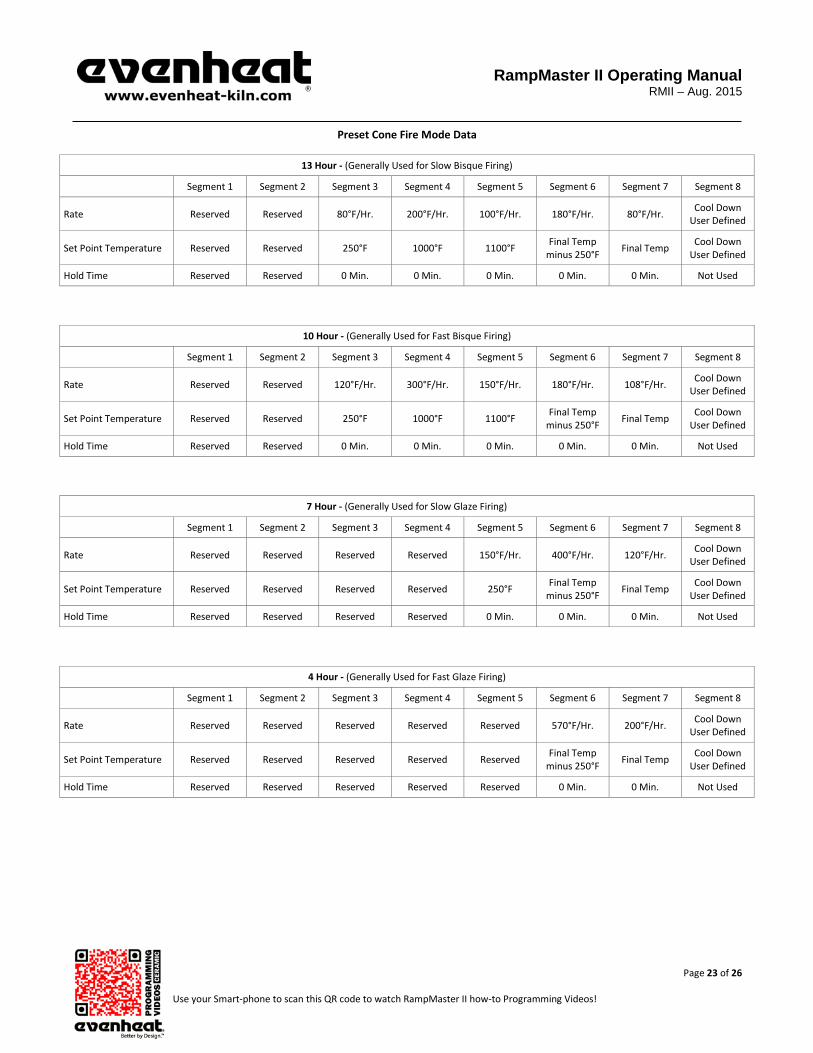
Preset Cone Fire Mode Data
13 Hour - (Generally Used for Slow Bisque Firing)
Segment 1 Segment 2 Segment 3 Segment 4 Segment 5 Segment 6 Segment 7 Segment 8
Rate Reserved Reserved 80°F/Hr. 200°F/Hr. 100°F/Hr. 180°F/Hr. 80°F/Hr. Cool Down User Defined
Set Point Temperature Reserved Reserved 250°F 1000°F 1100°F Final Temp minus 250°F Final Temp Cool Down
User Defined
Hold Time Reserved Reserved 0 Min. 0 Min. 0 Min. 0 Min. 0 Min. Not Used
10 Hour - (Generally Used for Fast Bisque Firing)
Segment 1 Segment 2 Segment 3 Segment 4 Segment 5 Segment 6 Segment 7 Segment 8
Rate Reserved Reserved 120°F/Hr. 300°F/Hr. 150°F/Hr. 180°F/Hr. 108°F/Hr. Cool Down User Defined
Set Point Temperature Reserved Reserved 250°F 1000°F 1100°F Final Temp minus 250°F Final Temp Cool Down
User Defined
Hold Time Reserved Reserved 0 Min. 0 Min. 0 Min. 0 Min. 0 Min. Not Used
7 Hour - (Generally Used for Slow Glaze Firing)
Segment 1 Segment 2 Segment 3 Segment 4 Segment 5 Segment 6 Segment 7 Segment 8
Rate Reserved Reserved Reserved Reserved 150°F/Hr. 400°F/Hr. 120°F/Hr. Cool Down User Defined
Set Point Temperature Reserved Reserved Reserved Reserved 250°F Final Temp minus 250°F Final Temp Cool Down
User Defined
Hold Time Reserved Reserved Reserved Reserved 0 Min. 0 Min. 0 Min. Not Used
4 Hour - (Generally Used for Fast Glaze Firing)
Segment 1 Segment 2 Segment 3 Segment 4 Segment 5 Segment 6 Segment 7 Segment 8
Rate Reserved Reserved Reserved Reserved Reserved 570°F/Hr. 200°F/Hr. Cool Down User Defined
Set Point Temperature Reserved Reserved Reserved Reserved Reserved Final Temp minus 250°F Final Temp Cool Down
User Defined
Hold Time Reserved Reserved Reserved Reserved Reserved 0 Min. 0 Min. Not Used

RampMaster II Operating Manual
RMII – Aug. 2015
Page 24 of 26 Use your Smart-phone to scan this QR code to watch RampMaster II how-to Programming Videos!
Cone Table / Equivalent Cone Temperatures (Factory Settings)
°F - Equivalent Cone Temperatures Taken from 108°F Table
Cone Temperature Cone Temperature Cone Temperature Cone Temperature
022 1087°F 014 1485°F 06 1828°F 3 2106°F
021 1112°F 013 1539°F 05 1888°F 4 2124°F
020 1159°F 012 1582°F 04 1945°F 5 2167°F
019 1252°F 011 1607°F 03 1987°F 6 2232°F
018 1319°F 010 1657°F 02 2016°F 7 2262°F
017 1360°F 09 1688°F 01 2046°F 8 2280°F
016 1422°F 08 1728°F 1 2079°F 9 2300°F
015 1456°F 07 1789°F 2 2088°F 10 2345°F
°C - Equivalent Cone Temperatures Taken from 108°F Table
Cone Temperature Cone Temperature Cone Temperature Cone Temperature
022 586°C 014 807°C 06 998°C 3 1152°C
021 600°C 013 837°C 05 1031°C 4 1162°C
020 626°C 012 861°C 04 1063°C 5 1186°C
019 678°C 011 875°C 03 1086°C 6 1222°C
018 715°C 010 903°C 02 1102°C 7 1239°C
017 738°C 09 920°C 01 1119°C 8 1249°C
016 772°C 08 942°C 1 1137°C 9 1260°C
015 791°C 07 976°C 2 1142°C 10 1285°C
RampMaster II Error Messages The RampMaster II monitors each firing and compares performance to a set of standards. If the firing does not meet performance standards the RampMaster II automatically stops the firing and displays a corresponding Error Code describing the fault. Pressing any key at this point, displays the elapsed time and temperature at which the error occurred. Make note of these values before clearing with the START/STOP key. Below is a list of error codes and their conditions. As noted on page 16 of this manual, there is a select group of Error Code standards that can be disabled. Normal ceramic work sometimes knowingly violates the error parameters so we allow these particular error codes to be disabled if desired. These codes are identified below. E– 0 Software error. General control failure. E– 1 Ascending ramp rate is less than 12°F per hour. Rate of rise is examined every 7-1/2 minutes. Condition must persist for 22-1/2 minutes
before the error is triggered. This error code is disabled when Error Codes are turned off. Probable causes are Control Relay Failure, Element Failure or Low Supply Voltage.
E– 2 While holding at programmed temperature, chamber temperature is above programmed hold temperature by 50+°F. Condition must persist for
19+seconds before error is triggered. This error code is disabled when Error Codes are turned off. Probable cause is Control Relay Failure. E– 3 While holding at programmed temperature, chamber temperature drops below programmed hold temperature by 50+°F. Condition must persist
for 19+ seconds before error is triggered. This error code is disabled when Error Codes are turned off. Probable causes are Control Relay Failure, Element Failure or Sudden Drop in Supply Voltage.

RampMaster II Operating Manual
RMII – Aug. 2015
Page 25 of 26 Use your Smart-phone to scan this QR code to watch RampMaster II how-to Programming Videos!
Error Messages Continued from Previous Page E– 4 During a descending ramp the chamber temperature is 50+°F above the previous hold temperature. Condition must persist for 19+ seconds before error is triggered. This error code is disabled when Error Codes are turned off. Probable cause is Control Relay Failure. E– 5 During a descending ramp the chamber temperature is 50+°F below the travelling set point. Condition must persist for 19+ seconds before error
is triggered. This error code is disabled when Error Codes are turned off. Probable causes are Control Relay Failure, Element Failure or Sudden Drop in Supply Voltage.
E– 6 Negative reading detected at thermocouple (temperature sensor). Thermocouple circuit installed incorrectly (polarity reversed at some point). E– 8 During an ascending ramp, chamber temperature is falling. Condition must persist for 22-1/2 minutes before the error is triggered. Probable
causes are Control Relay Failure, Element Failure or Sudden Drop in Supply Voltage. E– 9 Improper thermocouple installed or improper thermocouple software setting. Standard thermocouples for all Evenheat models is TYPE K. The
exception is our line of Crucible Furnaces which use TYPE S. E– A Invalid program variable. E–bd Excessive Control Board Temperature. E– d Chamber temperature 50+°F above travelling set point. This error code is disabled when Error Codes are turned off. Probable cause is Control
Relay Failure. E - - - RampMaster lost power while processing information. Double check program before firing. ErrP Brief Power Failure has occurred. ERRP is displayed alternately with firing temperature or hold time. Indicates that power was lost briefly and
restored. The firing program continues to operate. Pressing the Enter key one time during this condition removes the ERRP error code. PF Extended Power Failure has occurred. PF is displayed when the controller is powered up after an extended period of non-use (press Enter to
clear and get to Standby). PF is also displayed if power is lost during a firing and the chamber temperature was below 140°F (60°C) or the chamber temperature dropped more than 250°F during the power failure. In either case, the firing is stopped.
STUc Indicates that a key on the keypad is stuck in the pressed position. General Control Failure. FAIL Thermocouple (temperature sensor) circuit is faulty. Thermocouple circuit is broken at some point, usually the thermocouple itself. The
thermocouple circuit consists of the thermocouple, any connecting blocks and the thermocouple lead wire connecting to the RampMaster. For Error Codes not listed please contact Evenheat. Kiln Trouble Shooting Listed below are some of the more probable kiln problems you’ll encounter along with their most common cause and repair advice. Please feel free to contact Evenheat for assistance when dealing with these and other potential kiln problems. No Display Check to see that the kiln is actually plugged in. It happens! Also check the circuit protection (breakers or fuses) to see that they are not tripped or open. Breakers and fuses don’t trip or open for no reason. They indicate a fault which should be investigated by licensed personnel. See below. Kiln Won’t Reach Temperature Error Codes associated with a kiln not reaching temperature are E– 1, E– 3, E– 5 and E– 8. A few possibilities here: A low voltage will certainly slow a kiln down and, if the drop is low enough, it may cause failure to reach temperature. Low voltage is generally associated with your power service or provider and is rarely a fault in the kiln. A failed element reduces the heat produced. Failed elements tend to be very visual and are easily seen. With the kiln off (not running and unplugged) have a look at the elements for any breaks. If you see no breaks in the heating element then suspect a relay problem.

RampMaster II Operating Manual
RMII – Aug. 2015
Page 26 of 26 Use your Smart-phone to scan this QR code to watch RampMaster II how-to Programming Videos!
Kiln Troubleshooting Continued from Previous Page A failed relay (fails to close) reduces the heat produced. While a relay failure acts like an element failure, a relay is not visible. If the heating elements appear to be intact replace the relay. Kiln won’t stop firing (won’t shut off) Error Codes associated with a kiln not shutting off are E– 2 or E-4 or E– d. Most likely a failed relay (failed closed). A failed relay may cause the kiln temperature to increase when it should be decreasing. Depending upon your particular kiln model you may see up to 6 relays used in its design. Identifying the failed relay is fairly simple as the element connected to it will remain on. Unplug the kiln and remove the kiln control panel. Simply follow the element leads to the relay to identify it. Relays are maintenance items and we recommend replacing all of them when needing to replace one. Check your program. While you won’t see the error codes if you’ve programmed incorrectly this problem is possible. Fail is Displayed The thermocouple (temperature sensor) circuit is faulty. The thermocouple circuit is broken at some point, usually the thermocouple itself. The thermocouple circuit consists of the thermocouple, any connecting blocks and the thermocouple lead wire connecting to the RampMaster II. Circuit Protection Opens (“Blown” Breaker or Fuse) Circuit protection can open for various reasons. The BIG TWO are a short circuit and overheating. We’ll look at each separately. Short circuits occur when line voltage finds it’s way to another line or ground. They are usually violent occurrences with lots of noise, flashes of light and maybe a bit of smoke! During a short circuit the amperage goes very high. This increase in amperage exceeds your breaker/fuse rating which causes them to open (“blow”). That’s exactly why they’re there. Short circuits generally happen immediately upon plugging the kiln in or running the firing. They generally do NOT happen after the kiln has been on for some time. Overheating of the breakers/fuses can cause them to open (“blow”). Overheating needs time to happen. If the kiln is running fine for a while and then the breakers or the fuses open we can be fairly confident that the problem is overheating and not a short circuit. Overheating reduces the amount of amperage a breaker/fuse will allow to pass before it opens. Overheating is caused by many factors, the most common are: loose wire connections at the breakers/fuses, the size of the wire “feeding” the kiln is too small, the electrical receptacle is faulty or breaker/fuse is faulty. Reasons for a Failed Heating Element Element failure is usually from contamination. Contamination is stuff like clay bits, splattered glaze, prop sand etc. that finds its way into the element groove. If you do have an element failure, double check the groove at the point of failure. Remove power form the kiln and attempt to remove any debris from the groove with a sharp tool. Not doing so may allow the debris to destroy the replacement element. Reasons for a Failed Relay Relays are the switches that turn the heating elements on and off. They are moving parts and they’re working all the time. Long, slow firings make the relays work more which shortens their overall lifespan. Relay replacement is expected at some point.