rajasthan institute of engineering & technology,jaipur ......thus the plane of active gyroscopic...
TRANSCRIPT

Rajasthan Institute of Engineering & Technology,Jaipur.
Department of Mechanical Engineering
I Mid Term examination
Session: 2018-19
VSemester & ME
Dynamics of Machines 5ME2A Time: 2hrs. Set-I M.M.:20
Instruction for students:
1. No provision for supplementary answer book.
Q.1 What do you understand by Governors? Derive the equation of lift of sleeve for Porter
Governor.
Ans.1The function of a governor is to regulate the mean speed of an engine, when there are
variations in the load e.g. when the load on an engine increases, its speed decreases, therefore
it becomes necessary to increase the supply of working fluid. On the other hand, when the
load on the engine decreases, its speed increases and thus less working fluid is required. The
governor automatically controls the supply of working fluid to the engine with the varying
load conditions and keeps the mean speed within certain limits. A little consideration will
show, that when the load increases, the configuration of the governor changes and a valve is
moved to increase the supply of the working fluid ; conversely, when the load decreases, the
engine speed increases and the governor decreases the supply of working fluid.
Porter Governor

.

Or
Q.1 A porter governor has equal arms each 250 mm long & pivoted on the axis of rotation Each
ball has a mass of 5 kg and the mass of central load on the sleeve is 25 kg. The radius of
rotation of the ball is 150 mm when the governor begins to lift & 200 mm when the governor
is at maximum speed .Find the minimum & maximum speeds & range of speed of the
governor.
Ans.1

Q.2 Explain the working of Pickering Governor & write their formulas of deflection.
Ans.2A Pickering governor is mostly used for driving gramophone. It consists of three straight
leaf springs arranged at equal angular intervals round the spindle. Each spring carries a
weight at the centre. The weights move outwards and the springs bend as they rotate about
the spindle axis with increasing speed. The upper end of the spring is attached by ascrew to
hexagonal nut fixed to the governor spindle. The lower end of the spring is attached to a
sleeve which is free to slide on the spindle. The spindle runs in a bearing at each end and is
driven through gearing by the motor. The sleeve can rise until it reaches a stop, whose
position is adjustable.
Let m = Mass attached at the centre of the leaf spring,
a = Distance from the spindle axis to the centre of gravity of the mass,
when the governor is at rest,
ω = Angular speed of the governor spindle,
δ = Deflection of the centre of the leaf spring at angular speed ω,
a + δ = Distance from the spindle axis to the centre of gravity of the mass,
when the governor is rotating, and
λ = Lift of the sleeve corresponding to the deflection δ.
We know that the maximum deflection of a leaf spring with both ends fixed and carrying a
load (W) at the centre is,
Or
Q.2 A Hartnell Governor having a sleeve spring & two right angled bell crank levers moves
between 290rpm & 310rpm for a sleeve lift of 15mm The sleeve arms & the ball arms are
80mm & 120mm respectively. The lavers are pivoted at 120mm from the governor axis &
mass of each ball is 2.5 kg The ball arms parallel to the governor axis at the lowest
equilibrium speed .Determine loads on the spring at the lowest & highest equilibrium speed.

Ans.2

Q.3 Explain the effect of Gyroscopic Couple on a Naval ship during Steering ,Pitching and
Rolling with neat sketch .
Ans.3 (1)Effect of Gyroscopic Couple on a Naval Ship during Steering
Steering is the turning of a complete ship in a curve towards left or right, while it moves
forward. Consider the ship taking a left turn, and rotor rotates in the clockwise direction
whenviewed from the stern,When the rotor of the ship rotates in the clockwise direction
when viewed from the stern, it will have its angular momentum vector in the direction ox as
shown. As the ship steers to the left, the active gyroscopic couple will change the angular
momentum vector from ox to ox′. The vector xx′ now represents the active gyroscopic
couple and is perpendicular to ox. Thus the plane of active gyroscopic couple is
perpendicular to xx′ and its direction in the axis OZ for left hand turn is clockwise The
reactive gyroscopic couple of the same magnitude will act in the opposite direction (i.e. in
anticlockwise direction). The effect of this reactive gyroscopic couple is to raise the bow
and lower the stern.When the ship steers to the right under similar conditions as discussed
above, the effect of the reactive gyroscopic couple will be to raise the stern and lower the
bow. When the rotor rates in the anticlockwise direction,when viewed from the stern and the
ship is steering to the left, then the effect of reactive gyroscopic couple will be to lower the
bow and raise the stern.
(2) Effect of Gyroscopic Couple on a Naval Ship during Pitching
Pitching is the movement of a complete ship up and down in a vertical plane about transverse
axis, In this case, the transverse axis is the axis of precession. The pitching of the ship is assumed
to take place with simple harmonic motion i.e. the motion of the axis of spin about transverse
axis is simple harmonic. When the pitching is upward, the effect of the reactive gyroscopic
couple will try to move the ship toward star-board. On the other hand, if the pitching is
downward, the effect of the reactive gyroscopic couple, is to turn the ship towards port side.
Effect of Gyroscopic Couple on a Naval Ship during Rolling
The effect of gyroscopic couple to occur, the axis of precession should always be perpendicular
to the axis of spin. If, however, the axis of precession becomes parallel to the axis of spin, there
will be no effect of the gyroscopic couple acting on the body of the ship.In case of rolling of a
ship, the axis of precession (i.e. longitudinal axis) is always parallel to the axis of spin for all
positions. Hence, there is no effect of the gyroscopic couple acting on the body of a ship.

Or
Q.3 Drive a relation for stability of a four Wheel drive moving in a Curved Path.
Ans.3 Stability of a Four Wheel Drive Moving in a Curved Path
A little considereation will show,that the weight of the vehicle (W) will be equally distributed
over the four wheels which will act downwards. The reaction between each wheel and the road
surface of the same magnitude will act upwards.Therefore Road reaction over each wheel
= W/4 = m.g /4 newtons
1. Effect of the gyroscopic couple
Since the vehicle takes a turn towards left due to the precession and other rotating parts,
therefore a gyroscopic couple will act.

The positive sign is used when the wheels and rotating parts of the engine rotate in the same
direction. If the rotating parts of the engine revolves in opposite direction, then negative sign is
used.Due to the gyroscopic couple, vertical reaction on the road surface will be produced. The
reaction will be vertically upwards on the outer wheels and vertically downwards on the inner
wheels.Let the magnitude of this reaction at the two outer or inner wheels be P newtons. Then
P × x = C or P = C/x
∴ Vertical reaction at each of the outer or inner wheels,
P /2 = C/ 2x
2. Effect of the centrifugal couple
Since the vehicle moves along a curved path, therefore centrifugal force will act outwardly at
the centre of gravity of the vehicle. The effect of this centrifugal force is also to overturn the
vehicle.
We know that centrifugal force,
Q.4 Derive a relation for Energy stored in a Flywheel
Ans.4 Flywheel controls the speed variations caused by the fluctuation of the engine
turning moment during each cycle of operation.

Energy Stored in a Flywheel
When a flywheel absorbs energy, its speed increases and when it gives up energy, its speed
decreases.
Let m = Mass of the flywheel in kg,
k = Radius of gyration of the flywheel in metres,
I = Mass moment of inertia of the flywheel about its axis of rotation in kg-m 2 = m.k 2 ,
N 1 and N 2 = Maximum and minimum speeds during the cycle in r.p.m.,
ω 1 and ω 2 = Maximum and minimum angular speeds during the cycle in rad/s,
Or
Q.4 Differentiate Simple & Reverted gear train with neat sketch.
Ans.4 Simple Gear Train
When there is only one gear on each shaft, it is known as simple gear train. The gears are represented by
their pitch circles.When the distance between the two shafts is small,the two gears 1 and 2 are made to
mesh with each other to transmit motion from one shaft to the other, as shown in Fig. 13.1 (a). Since the
gear 1 drives the gear 2, therefore gear 1 is called the driver and the gear 2 is called the driven or follower.
It may be noted that the motion of the driven gear is opposite to the motion of driving gear. Since the
speed ratio (or velocity ratio) of gear train is the ratio of the speed of the driver to the speed of the driven
or follower and ratio of speeds of any pair of gears in mesh is the inverse of their number of teeth,
therefore It may be noted that ratio of the speed of the driven or follower to the speed of the driver is
known as train value of the gear train.

Reverted Gear Train
When the axes of the first gear (i.e. first driver) and the last gear (i.e. last driven or follower) are
co-axial,then the gear train is known as reverted gear train that gear 1 (i.e. first driver) drives the
gear 2 (i.e. first driven or follower) in the opposite direction. Since the gears 2 and 3 are mounted
on the same shaft, therefore they form a compound gear and the gear 3 will rotate in the same
direction as that of gear 2. The gear 3 (which is now the second driver) drives the gear 4(i.e. the
last driven or follower) in the same direction as that of gear 1. Thus we see that in a reverted gear
train, the motion of the first gear and the last gear is like.
Let T 1 = Number of teeth on gear 1, r 1 = Pitch circle radius of gear 1, and
N 1 = Speed of gear 1 in r.p.m.Similarly,
T 2 , T 3 , T 4 = Number of teeth on respective gears,
r 2 , r 3 , r 4 = Pitch circle radii of respective gears, and
N 2 , N 3 , N 4 = Speed of respective gears in r.p.m.
Since the distance between the centres of the shafts of gears 1 and 2 as well as gears 3 and 4
is same, therefore
r 1 + r 2 = r 3 + r 4 ...(i)
Also, the circular pitch or module of all the gears is assumed to be same, therefore number of
teeth on each gear is directly proportional to its circumference or radius.
∴ *T 1 + T 2 = T 3 + T 4

Rajasthan Institute of Engineering & Technology,Jaipur.
Department of Mechanical Engineering
I Mid Term examination
Session: 2018-19
VSemester & ME
Dynamics of Machines 5ME2A Time: 2hrs. Set-II M.M.:20
Instruction for students:
1. No provision for supplementary answer book.
Q.1 Differentiate between Governor and Flywheel? Writedown the classification of Governors.
Ans.1
Sr. No. Flywheel Governor
1.
Maintains constant
speed but the means is
different from that of
Governor.
Stores excess of
rotational energy from
the power stroke and
supply back during non-
power strokes of the
cycle
Maintains constant speed but
the means is different from that
of Flywheel.
Controls mean speed of the
engine under full/half/varying
load conditions by regulating
the supply of working fluid to
the engine
2.
In this, there are energy
variations but runs the
crankshaft at constant
speed in each stroke of
the cycle
When load on the engine
increases, speed decreases. It
increases the flow of fuel to
keep the constant mean speed
3. Flywheel controls the
speed for one cycle only
Governor maintains constant
mean speed over a period of
time.
4.
Flywheel is not required
in all the prime movers
(engines)
Governor is required in all the
prime movers (engines)
5. It is a heavy machine
part
It is a relatively light machine
part
6. Has large moment of
inertia
Relatively small moment of
inertia
7. Rotating part Non- Rotating part
8. Running charges are
less Running charges are high
9.
Angular speed increases
while storing energy
and decreases during
supply back of energy
Runs at mean speed under all
loads on the engine

10. Crankshaft runs at
constant speed
Load increases speed decreases
and vice -varsa. But it controls
the MEAN speed by
controlling the flow of fuel in
the engine
11.
There are no valves
attached with the
flywheel
Valves are there and there
opening is controlled by the
centrifugal force on the balls
attached
Or
Q.1 A porter governor has equal arms each 250 mm long & pivoted on the axis of rotation,Each
ball has a mass of 5 kg & the mass of central load on the sleeve is 25 kg. The radius of
rotation of the ball is 150 mm when the governor begins to lift & 200 mm when the governor
is at maximum speed .Find the minimum & maximum speeds & range of speed of the
governor
Ans.1

Q.2 In a Proell governor has equal arms of length 300 mm,The upper & lower arms are pivoted
on the axis of governor.The extension arm of lower link each 80 mm long & parallel to to
the axis of when the radious of rotation of balls is 150 mm and 200 mmm.The mass of each
ball 10 kg & mass of the central load 100 kg.determine the range of governor
Ans.2
Or
Q.2. Write short notes:-Any two
(a) Isochronous Governor (b) Sensitiveness of governor (c) Governor Hunting
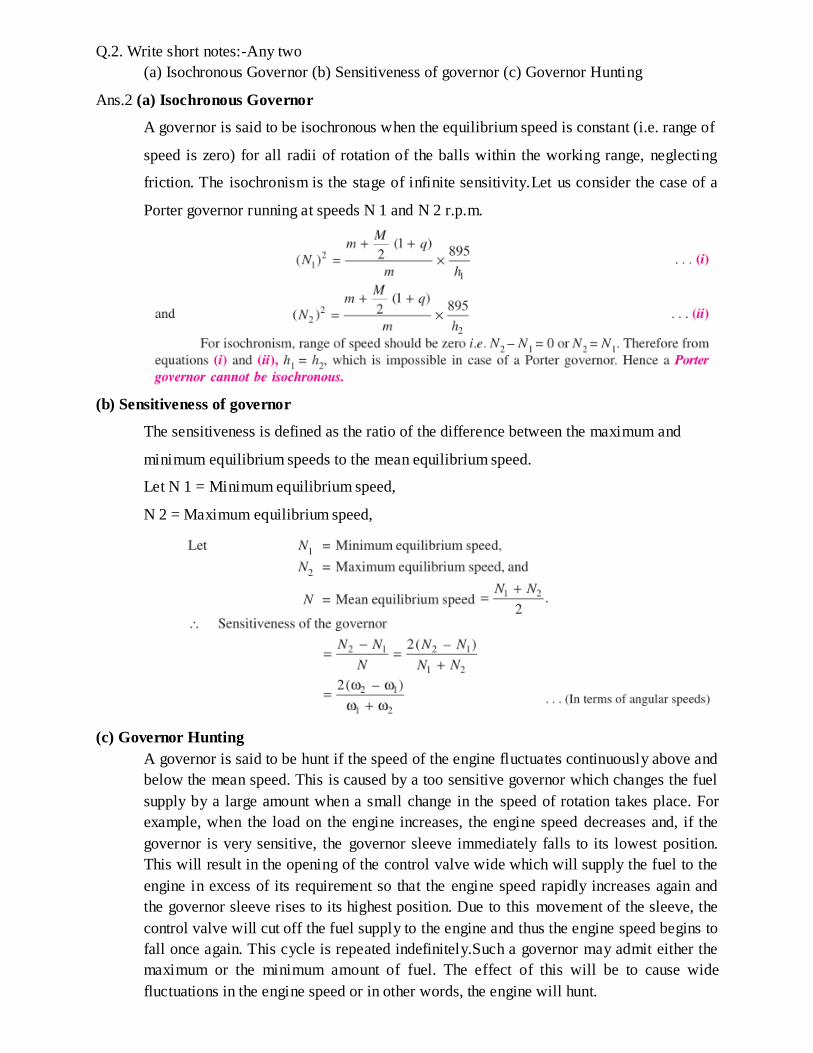
Ans.2 (a) Isochronous Governor
A governor is said to be isochronous when the equilibrium speed is constant (i.e. range of
speed is zero) for all radii of rotation of the balls within the working range, neglecting
friction. The isochronism is the stage of infinite sensitivity.Let us consider the case of a
Porter governor running at speeds N 1 and N 2 r.p.m.
(b) Sensitiveness of governor
The sensitiveness is defined as the ratio of the difference between the maximum and
minimum equilibrium speeds to the mean equilibrium speed.
Let N 1 = Minimum equilibrium speed,
N 2 = Maximum equilibrium speed,
(c) Governor Hunting
A governor is said to be hunt if the speed of the engine fluctuates continuously above and
below the mean speed. This is caused by a too sensitive governor which changes the fuel
supply by a large amount when a small change in the speed of rotation takes place. For
example, when the load on the engine increases, the engine speed decreases and, if the
governor is very sensitive, the governor sleeve immediately falls to its lowest position.
This will result in the opening of the control valve wide which will supply the fuel to the
engine in excess of its requirement so that the engine speed rapidly increases again and
the governor sleeve rises to its highest position. Due to this movement of the sleeve, the
control valve will cut off the fuel supply to the engine and thus the engine speed begins to
fall once again. This cycle is repeated indefinitely.Such a governor may admit either the
maximum or the minimum amount of fuel. The effect of this will be to cause wide
fluctuations in the engine speed or in other words, the engine will hunt.

Q.3 Explain the effect of Gyroscopic Couple on a Naval ship during Steering ,Pitching and
Rolling with neat sketch.
Ans.3 (1)Effect of Gyroscopic Couple on a Naval Ship during Steering
Steering is the turning of a complete ship in a curve towards left or right, while it moves
forward. Consider the ship taking a left turn, and rotor rotates in the clockwise direction
whenviewed from the stern,When the rotor of the ship rotates in the clockwise direction
when viewed from the stern, it will have its angular momentum vector in the direction ox as
shown. As the ship steers to the left, the active gyroscopic couple will change the angular
momentum vector from ox to ox′. The vector xx′ now represents the active gyroscopic
couple and is perpendicular to ox. Thus the plane of active gyroscopic couple is
perpendicular to xx′ and its direction in the axis OZ for left hand turn is clockwise The
reactive gyroscopic couple of the same magnitude will act in the opposite direction (i.e. in
anticlockwise direction). The effect of this reactive gyroscopic couple is to raise the bow
and lower the stern.When the ship steers to the right under similar conditions as discussed
above, the effect of the reactive gyroscopic couple will be to raise the stern and lower the
bow. When the rotor rates in the anticlockwise direction,when viewed from the stern and the
ship is steering to the left, then the effect of reactive gyroscopic couple will be to lower the
bow and raise the stern.
(2) Effect of Gyroscopic Couple on a Naval Ship during Pitching
Pitching is the movement of a complete ship up and down in a vertical plane about transverse
axis, In this case, the transverse axis is the axis of precession. The pitching of the ship is assumed
to take place with simple harmonic motion i.e. the motion of the axis of spin about transverse
axis is simple harmonic. When the pitching is upward, the effect of the reactive gyroscopic
couple will try to move the ship toward star-board. On the other hand, if the pitching is
downward, the effect of the reactive gyroscopic couple, is to turn the ship towards port side.
Effect of Gyroscopic Couple on a Naval Ship during Rolling
The effect of gyroscopic couple to occur, the axis of precession should always be perpendicular
to the axis of spin. If, however, the axis of precession becomes parallel to the axis of spin, there
will be no effect of the gyroscopic couple acting on the body of the ship.In case of rolling of a
ship, the axis of precession (i.e. longitudinal axis) is always parallel to the axis of spin for all
positions. Hence, there is no effect of the gyroscopic couple acting on the body of a ship.

Or
Q.3The Controlling force Fc in Newton & Radius of rotation( r) in meter for Spring controlled
governor is expressed by- Fc = 2800r-76
The Mass of ball is 5 kg & extreme radius of rotation of balls is 100 mm & 175 mm .Find the
Maximum & Minimum speeds of equilibrium.
Ans.3
Q.4 Established a relation for stability of a Two wheeler motorcycle moving in a Curved Path
Ans.4 Stability of a Two wheeler motorcycle moving in a Curved Path
Consider a two wheel vehicle (say a scooter or motor cycle) taking a right turn

Let m = Mass of the vehicle and its rider in kg,
W = Weight of the vehicle and its rider in newtons = m.g,
h = Height of the centre of gravity of the vehicle and rider,
r W = Radius of the wheels, R = Radius of track or curvature,
I W = Mass moment of inertia of each wheel,
I E = Mass moment of inertia of the rotating parts of the engine,
ω W = Angular velocity of the wheels,
ω E = Angular velocity of the engine,
G = Gear ratio = ω E / ω W ,
v = Linear velocity of the vehicle = ω W × r W ,
θ = Angle of heel. It is inclination of the vehicle to the vertical for equilibrium.
Let us now consider the effect of the gyroscopic couple and centrifugal couple on the vehicle,
as discussed below.
1. Effect of gyroscopic couple
A little consideration will show that when the wheels move over the curved path, the vehicle
is always inclined at an angle θ with the vertical plane This angle is known as angle of heel. In
other words, the axis of spin is inclined to the horizontal at an angle θ, Thus the angular
momentum vector Iω due to spin is represented by OA inclined to OX at an angle θ. But the
precession axis is vertical. Therefore the spin vector is resolved along OX.
2. Effect of centrifugal couple

Or
Q.4 Construct a table for calculating the Speed ration of Simle Epicyclic gear train with neat
sketch.
Ans.4 Simle Epicyclic gear train
A simple epicyclic gear train is where a gear A and the arm C have
a common axis at O 1 about which they can rotate. The gear B
meshes with gear A and has its axis on the arm at O 2 , about which
the gear B can rotate. If the arm is fixed, the gear train is simple and
gear A can drive gear B or vice- versa, but if gear A is fixed and the
arm is rotated about the axis of gear A (i.e. O 1 ), then the gear B is
forced to rotate upon and around gear A. Such a motion is called
epicyclic and the gear trains arranged in such a manner that one or
more of their members move upon and around another member are
known as epicyclic gear trains (epi. means upon and cyclic means
around). The epicyclic gear trains may be simple or compound.