rainwater management - public.resource.org · rainwater management ... drain: a drain is ... the...
TRANSCRIPT

Part 8 Building Services 8‐291
Chapter 7
Rainwater Management
7.1 PURPOSE
The purpose of this chapter is to set forth provisions for planning, design and installation of rainwater management systems in buildings.
7.2 SCOPE
7.2.1
This chapter specifies the general requirements for rain water harvesting for different categories of buildings according to their occupancy classification together with all ancillary works of ground water recharging such as perforated piping, pits and inspection chambers.
7.2.2
This chapter also covers the design, installation and maintenance of elements for rain water drainage systems around the building and led to public storm sewers or to nearby suitable surface water system.
7.2.3
The storm water drainage on ground is not covered by this Code.
7.3 TERMINOLOGY
This section provides an alphabetical list of all terms used and applicable to this chapter of the Code. In case of any conflict or contradiction between a definition given in this section and that in any other chapter or part of the Code, the meaning specified in this chapter shall govern for interpretation of the provisions of this chapter.
BEDDING FACTOR: The ratio of the product of design load and factor of safety to the minimum crushing strength.
BRANCH: Any part of the piping system other than a main or riser.
BUILDING DRAIN : The building (house) drain is that part of the lowest piping or open channel of a drainage system which receives the discharges from soil, waste, and other drainage systems inside the walls of the building and conveys the same to the building (house) sewer, beginning at 0.9 m outside the building wall.
BUILDING SEWER : The building (house) sewer is that part of the horizontal piping of a drainage system which extends from the end of the building drain and which receives the discharge of the building drain and conveys it to a public sewer, private sewer, individual sewage disposal system, or other point of disposal. Also known as SEWER.
BUILDING STORM DRAIN : A building (house) storm drain is a building drain used for conveying rain water, surface water, ground water, subsurface water, condensate, cooling water, or other similar discharge to a building storm sewer or a combined sewer, extending to a part not less than 0.9 m outside the building wall. Also known as STORM DRAIN.
DRAIN: A drain is any pipe or open channel which carries waste water or waterborne wastes in a building drainage system.
DRAINAGE SYSTEM: A drainage system (drainage piping) includes all the piping within public or private premises, which conveys sewage, rain water, or other liquid wastes to a legal point of disposal, but does not include the mains of a public sewer system or a private or public sewage treatment or disposal plant.
DRINKING FOUNTAIN: A fountain or a tap raised from the floor with potable water supply connection.

Part 8 Building Services
6‐292 Vol. 3
EXISTING WORK: The existing work is a plumbing system or any part thereof which was installed prior to the date of enforcement of this Code.
FIXTURE UNIT: A fixture unit is a quantity in terms of which the load producing effects on the plumbing system of different kinds of plumbing fixtures are expressed on some arbitrarily chosen scale.
FLUSH VALVES: A flush valve is a device located at the bottom of the tank for the purpose of flushing water closets and similar fixtures.
FRENCH DRAIN: A shallow trench filled with coarse rubble, clinker or similar material with or without field drain pipes.
GRADE: The grade is the slope or fall of a line of pipe in reference to a horizontal plane. In drainage it is usually expressed as the fall in mm per m length of pipe.
HORIZONTAL BRANCH : A horizontal branch is a drain pipe extending laterally from a soil or waste stack or building drain, with or without vertical sections or branches, which receives the discharge from one or more fixture drains and conducts it to the soil or waste stack or to the building (house) drain.
HORIZONTAL PIPE: A horizontal pipe is any pipe or fitting which is installed in a horizontal position or which makes an angle of less than 45 degrees with the horizontal.
INTERCEPTOR: An interceptor is a device designed and installed so as to separate and retain deleterious, hazardous, or undesirable matter from normal wastes and permit normal or liquid wastes to discharge into the disposal terminal by gravity.
INVERT: The lowest point of the internal surface of a pipe or channel at any cross‐section.
LEADER : A vertical drainage pipe that carries rainwater from roof or gutter drain to building storm drain or building drain or private disposal system.
LIQUID WASTE: The liquid waste is the discharge from any fixture, appliance, or appurtenance in connection with a plumbing system which does not receive fecal matter.
LOAD FACTOR: The load factor is the percentage of the total connected fixture unit flow rate which is likely to occur at any point in the drainage system. It varies with the type of occupancy, the total flow unit above the point being considered, and with the probability factor of simultaneous use.
MAIN: The main of any system of continuous piping is the principal artery of the system, to which branches may be connected.
MAIN SEWER: See Public Sewer.
MANHOLE : An opening by which a man may enter or leave a drain, a sewer or other closed structure for inspection, cleaning and other maintenance operations, fitted with a suitable cover.
MANHOLE CHAMBER: A chamber constructed on a drain or sewer so as to provide access thereto for inspection, testing or the clearance of obstruction.
OFFSET: An offset in a line of piping is a combination of elbows or bends which brings one section of the pipe out of line but into a line parallel with the other section.
PUBLIC SEWER: A public sewer is a common sewer directly controlled by public authority. Also known as MAIN SEWER.
RISER: A water supply pipe that extends vertically one full storey or more to convey water to branches or fixtures.
SANITARY SEWER: A sanitary sewer is a pipe which carries sewage and excludes storm, surface, and ground water. Also known as SEWER.
SEEPAGE PIT: See SOAK PIT.
SEWAGE: The sewage is any liquid waste containing animal or vegetable matter in suspension or solution and may include liquids containing chemicals in solution.
SEWER: See BUILDING SEWER or PUBLIC SEWER or SANITARY SEWER or STORM SEWER.
SLUDGE: A settled portion of the sewage or waste water effluent from a sedimentation tank in semi‐solid condition.
SOAK PIT: A pit, dug into permeable soil lined to form a covered perforated chamber or filled with sand at the bottom and gravel or broken bricks at the top into which effluent from a septic tank or storm water is led and from which these may soak away into the ground. Also known as SEEPAGE PIT or SOAK WELL.
SOAK WELL: See SOAK PIT.

Rainwater Management Chapter 7
Bangladesh National Building Code 2011 6‐293
SOIL PIPE: A soil pipe is any pipe which conveys the discharge of water closets, urinals, or fixtures having similar functions, with or without the discharge from other fixtures, to the building drain or building sewer.
STACK: A stack is the vertical main of a system of soil, waste, or vent piping.
STORM DRAIN: See Building Storm Drain.
STORM SEWER: A storm sewer is a sewer used for conveying rain water, surface water, condensate, cooling water, or similar liquid wastes, exclusive of sewage and industrial waste. Also known as SEWER.
SUBSOIL DRAIN: A subsoil drain is a drain which receives only subsurface or seepage water and conveys it to a place of disposal.
SULLAGE: The discharge from wash basins, sinks and similar appliances, which does not contain human or animal excreta.
SUMP: A sump is a tank or pit which receives sewage or liquid waste, located below the normal grade of the gravity system, and which must be emptied by mechanical means.
SUPPORTS: The supports, hangers, and anchors are devices for supporting and securing pipe and fixtures to walls, ceilings, floors, or structural members.
TRAP: A trap is a fitting or device so designed and constructed as to provide, when properly vented, a liquid seal which will prevent the back passage of air without materially affecting the flow of sewage or waste water through it.
TRAP SEAL: The trap seal is the maximum vertical depth of liquid that a trap will retain, measured between the crown weir and the top of the dip of the trap.
VERTICAL PIPE: A vertical pipe is any pipe or fitting which is installed in a vertical position or which makes an angle of not more than 45 degrees with the vertical.
WASTE PIPE: A waste pipe is a pipe which conveys only liquid waste free of fecal matter.
7.4 Rainwater Harvesting Requirements
7.4.1 General
Every building proposed for constructing on plots having extent of 300 sqm or above shall have facilities for conserving and harvesting rainwater.
7.5 Rainwater Harvesting Plans
7.5.1 Requirement of Permit
Rainwater harvesting and drainage system shall not be installed until a permit for such work has been issued by the Building Authority for existing (only for addition or for alteration) or new building or for any other premises.
7.5.2 Application for Permit
An application for a permit for rainwater harvesting and drainage work shall be made on a prescribed form (see Appendix 8.6.F) by the licensed plumber and the owner, or by his appointed person or agent to install all or a self‐contained or workable part of such work. The application shall accompany building rainwater harvesting and drainage plans and adequate description of the proposed rainwater harvesting and drainage installation in a drawing (drawn to a scale not less than 1:100) with the following details:
(a) Plan of the building and site lay out;
(b) Rainwater harvesting;
(c) Ground recharging system;
(d) Storm drainage system;
(e) Catchment areas;
(f) Materials, sizes and gradients of all proposed piping;
Part 8 Building Services
6‐294 Vol. 3
(g) The position of manhole, rainwater pipe, gutters, rainwater inlets, etc. in the premises and their connection with storm sewer system or surface waters; the following colours may be used to indicate sewers, rainwater pipes and existing works:
Proposed storm sewers and disposal pipes ‐ violet
Existing network ‐ black
(h) The slope of catchments.
7.5.3
In addition to rainwater harvesting and drainage plan a separate site plan of the building shall be submitted with the following particulars:
(a) Adjoining plots and streets with their identification;
(b) The position and invert level of the storm sewers, (if any), surface drain water and the direction of flow in it;
(c) The level of the proposed drainage pipe connecting to the storm sewers (if any);
(d) The position and layout of private storm drainage system (in absence of public storm sewers); and
(e) The alignment, size and gradients of all harvesting and drainage piping.
7.5.4
For high rise and public buildings, design calculations and specifications for various items of the work involved shall be submitted along with the drawings.
7.5.5 Permits and Approvals
The building official shall examine or cause to be examined all applications for permits and, amendments thereto within 45 days. If the application does not conform to the requirements of all pertinent laws, such application shall be rejected in writing, stating the reasons therefore. If the proposed work satisfies all the Code requirements, the Authority shall issue a nontransferable permit.
7.6 LICENSING OF PLUMBER
7.6.1 License Requirement
No individual, partnership, corporation or firm shall engage in the business of installation, repair or alteration of rainwater harvesting and drainage work without obtaining a license from the Authority.
7.6.2 Examination and Certification
The Building Authority shall establish a plumbers examination board. The board will determine the requirements for the qualification and procedures for examination of applicants for license. The Authority will issue license to such applicants who meet the qualifications therefore and successfully pass the examination conducted by the board.
7.6.3 Annulment of License
The license of a licensed plumber may be nullified by the Building Authority, if it is proved that a plumbing work has been completed and certified by the licensed plumber violating the provisions of this Code deliberately setting aside the approvals given in the permit or without receiving the permit from the Building Authority.
7.7 Rainwater Harvesting
7.7.1 General
Rainwater can be conserved and used in all useful purposes related to use of water. The amount of rain water to be conserved depends upon the purpose of use, rainfall intensity at the locality and the available catchments

Rainwater Management Chapter 7
Bangladesh National Building Code 2011 6‐295
from where rainwater shall be collected. Rainwater can also be used for artificial ground water recharging. Two major aspects of rainwater harvesting are as follows.
(a) Roof top rain‐water harvesting, and (b) Artificial ground water recharge.
7.8 Roof Top Rainwater Harvesting
Water can be collected through roof gutters and rainwater down pipes. Provision shall be made to divert the first rainfall after dry spell to avoid dust, soot, and leaves etc. in the water to be collected into the water tank. The capacity of the water tank should be enough for storing water required for consumption between two dry spells.
7.8.1 Precautions in Rainwater Harvesting
Following precautions shall be well cared
(a) No sewage or waste water should be admitted into the system.
(b) Wastewater from areas likely to have oil, grease or other pollutants shall not be connected to the system.
(c) Each rainwater seepage well shall have an inlet chamber with a silt trap to prevent any silt from finding its way into the sub‐soil water.
(d) The wells should be terminated at least 5 m above the natural static sub‐soil water at its highest level so that the incoming flow passes through the natural ground condition and prevents contamination hazards.
(e) No recharge structure or a well shall be used for drawing water for any purpose.
7.8.2 Qualifying Rainwater for Harvesting.
Rainwater shall be treated adopting following methods mentioned according to the purpose of use:
(a) For using rainwater in drinking, cooking, washing utensils bathing and ablution it shall be disinfected along with filtration.
(b) For cloth washing, floor washing, fountain, water fall cascade etc , rainwater shall be filtered. (c) For using in sprinkler fire fighting, air conditioning etc sedimentation of suspended particles will be
required.
(d) For toilet flushing, gardening, cleaning artificial ground, parking lots etc screening floating materials are needed.
7.8.3 Catchments area for Collecting Rainwater
Rainwater can be collected from following built up areas for harvesting.
(a) Roof top surfaces (b) External walls and other vertical surfaces (c) Balconies, sunshades etc. (d) Metal surface of play grounds, open yards etc.
7.8.4 Determining Catchment Area
For flat surface, the catchment area is its plan area plus 50 per cent of the adjoining vertical wall contributing rainwater accumulation on the concerned catchment. See appendix 8.6.E.
For sloping roof, catchment is considered to be the actual inclined roof area.
7.8.5 Storing Rainwater
Where rainwater will be used for domestic purpose, rainwater from roof or terrace may be led straight from conductor (or leader) to one or more storage tanks. Storage tanks shall be provided with ventilating covers. An arrangement shall be made in the rainwater leader to divert the first washings from the roof or terrace catchments as they will contain more undesirable materials. The open end of all pipes shall be covered with mosquito (insect) proof wire net.

Part 8 Building Services
6‐296 Vol. 3
7.8.6 Flushing out First Rainwater
Before storing initial rainwater, just after starting raining, shall be drained out for a period as mentioned below.
Location Time
Dhaka metropolitan area 20 min
Sylhet 15 min
Chittagong 15 min
Other urban areas 15 min
7.8.7 Precautions for Rainwater Storage
Following precautionary measures shall be taken for rainwater storage.
(a) Storage tank shall be made water tight in all respect.
(b) Tank shall always be kept covered. (c) Regular cleaning at least once a year, preferably at end of dry periods, shall be done. (d) Disinfection shall be done after cleaning operation. (e) Tank shall be ventilated and vent pipe shall be covered by mosquito net.
(f) The tank must have an overflow pipe leading to a natural water course.
(g) If raw rainwater and potable water is to be stored in the same storage tank separated by a separating wall, then the separating wall shall have no openings.
7.8.8 Rainwater Treatment
For potable systems, a plain galvanized roof or a metal roof with epoxy or latex paint is recommended. Composite or asphalt shingles are not advisable, to improve water quality, disinfection shall be done in the following way.
7.8.8.1 Chlorination
Chlorine must be present in a concentration of 1 ppm to achieve disinfection. Liquid chlorine, in the form of laundry bleach, usually has 6 percent available sodium hypochlorite. For disinfection purposes, 2 fluid ounces (¼ cup) must be added per 1,000 gallons of rainwater. Bleach products, however, not labeled cannot be used in water treatment. A purer form of chlorine, which comes in solid form, is calcium hypochlorite, usually with 75 percent available chlorine. At that strength, 0.85 ounces by weight in 1,000 gallons of water would result in a level of 1 ppm. Chlorine contact times are shown in Table 8.7.1. To filter out Giardia and Cryptosporidum cysts, an absolute 1‐ micron filter shall be used.
Table 8.7.1 : Contact Time with Chlorine
Water
pH
Water temperature
50 oF or warmer 45 oF 40 oF or colder
Contact time in minutes
6.0 3 4 5
6.5 4 5 6
7.0 8 10 12
7.5 12 15 18
8.0 16 20 24
7.8.9 Determining Volume of Rainwater Storage
Determining volume of rainwater storage
Rainwater storage volume in cum = 1000⁄
where D = Rainwater demand In liter per capita per day.
N = Population number.
Rainwater Management Chapter 7
Bangladesh National Building Code 2011 6‐297
D = Number of days for which water will be stored. Consider 90 days for drinking, cooking, utensils cleansing, bathing and ablution purposes; 210 days for other purposes.
7.8.10 Sizing of Rainwater Down Piping The size and number of vertical leaders or rainwater down pipes shall be based on the maximum projected roof area according to Table 8.7.2. Minimum two drains and vertical leaders shall be provided for any independent roof surface.
The size of semi‐circular gutter shall be based on maximum projected roof area according to Table 8.7.4.
7.8.11 INLET OF LEADERS Inlet of leaders on any open surfaces shall be provided with dome shaped gratings. Size of the Inlet of any vertical leader shall be one size bigger than the size of the corresponding vertical leader.
7.8.12 DESIGN OF RAINWATER DISTRIBUTION SYSTEM The design of rainwater distribution piping shall be in accordance with sec.5.10 of chapter 5.
7.9 Artificial Ground Water Recharge
Storm runoff should be used for augmentation of ground water reservoir where ground water depletion rate is more than one meter per year. Modifying the natural movement of surface water by constructing recharge structures (see Fig. 8.8.1) has the following objectives:
(a) Enhancement of sustainable yield in areas where there is over development and depletion of the aquifers.
(b) Conservation and storage of excess underground water in the aquifers. (c) Improvement of the quality of the existing ground water through dilution.
(d) Maintaining the natural balance of the ground water and its usage as the rain‐water is a renewable supply source
(e) Providing constant, dependable and safe water supply.
7.9.1 Designing Recharge Pit
Volume of recharge pit shall be on the basis of maximum intensity of rainfall in a shorter period of at least 15 minute. It is about one fourth peak hourly rainfall
Capacity of recharge tank = A × Is × f /p Where
A = Catchments area
Is= Intensity of rainfall in 15 minutes
f = Runoff co‐efficient and
p = Porosity of filter bed = 0.5

Part 8 Building Services
6‐298 Vol. 3
Fig 8.7.1. ARTIFICIAL GROUND WATER RECHARGE STRUCTURE
Large dry well can be constructed in accordance with the requirements for seepage pit (Sec 6.9.15). However, for small dry wells handling limited quantities of rainwater, the pit may consist of a one meter depth length of 1.0 0.45 m diameter pipe filled with crushed bricks stone.
7.10 DRAINAGE AND SANITATION REQUIREMENT
7.10.1 General
The object of storm water drainage is to collect and carry, the excess rain‐water accumulating within the premises of the building, for suitable disposal. In rainwater drainage system there shall be safeguard against fouling, deposition of solids and clogging and with adequate inspection chambers so arranged that the drains may be readily cleaned without the risk of health hazard.
7.10.2 Design Factors
Estimation of the quantity of storm water shall be based on the following factors
(a) Imperviousness of the surface
(b) Ground slope and time of concentration
(c) Intensity of the rainfall for a design period and (d) Duration of the rainfall.
7.10.3 Imperviousness of the Surface
The percentage of imperviousness of the drainage area may be obtained from available data for a particular area. In the absence of such data, the following values may serve as a guide:
Inlet
Coarse sand1.5 to 2mm
Gravel 5 to 10mm size
Boulder 5 to 20mm size
GL
3mm slot size
Ball plug

Rainwater Management Chapter 7
Bangladesh National Building Code 2011 6‐299
Imperviousness factor for different type of areas
Type of area (percent) Imperviousness factor
Commercial and industrial areas 70-90 Residential areas (high density) 60‐75
Residential areas (low density) 35‐60
Parks and underdeveloped areas 10‐20
7.10.4 Time of Concentration
Time of concentration to reach the farthest point of any drainage system or the outfall under consideration should be considered between 5 min to 30 min.
7.10.5 Intensity of the Rainfall
Rainwater Intensity data for the locality of the building shall be studied to arrive at the design parameters for rainwater harvesting in accordance with Appendix S.
7.10.6 Rainwater Disposal
Rainwater from roof or from building premises shall not be discharged into septic tank. This shall be drained into storm sewer or combined sewer system where available or into private disposal methods, water course or dry well, Fig 8.6.21 and 8.6.22.
7.10.6.1 Individual rain water traps shall be installed on the rainwater drain branch serving each leader or a single trap shall be installed in the main rainwater drain (building storm drain) just before its connection with the combined building sewer, main drain or public sewer.
7.10.6.2 No traps shall be required for rainwater drains which will be used for rainwater collection and connected to a sewer draining rainwater exclusively.
7.10.6.3 Subsurface drainage pipings for rainwater drainage shall not be less than 100 mm in diameter. The subsoil drainage system shall be protected by an accessibly located backwater valve in case the building is subject to backwater or flooding. Subsoil drains shall discharge to a trapped area drain, sump, dry well or an approved location above grade.
7.10.6.4 Rainwater pipes shall not be used as soil, waste or vent pipes.
7.10.6.5 All roof areas, except those draining to hanging gutters, shall be equipped with roof drains with strainers extending not less than 100 mm above the surface of the roof and shall have an available inlet area not less than two times the area of the leader to which the drain will be connected.
7.10.6.6 It is recommended to have more than one rainwater drainage pipe for primary roof drainage system to minimize blockage.
7.10.6.7 It is recommended to provide secondary rainwater drainage system at a suitable elevation from the roof that has been considered in the calculation of rainwater load to design the building structure. The secondary drainage system shall be a separate drainage piping up to a storm sewer or private waste (rainwater) disposal system. The size of secondary rainwater drainage piping shall not be less than the size required for primary rainwater drainage piping.
7.10.6.8 French drains may be employed as surface water drains for drainage of unpaved surfaces. Construction of french drains (if used) shall be in accordance with established engineering practices.
7.10.6.9 The design of such system shall be on the basis of location with respect to wells or other sources of water, soil permeability, ground water elevation, area available and maximum occupancy of the building.
Part 8 Building Services
6‐300 Vol. 3
7.11 MATERIALS AND APPLIANCES
The piping, fixtures and equipment to be used for rainwater harvesting and drainage system shall be in accordance with Sec 6.7 in Chapter 6.
7.12 Construction of Rainwater Storage Tank
The construction of storage tanks for rainwater storage shall be in accordance with Sec 5.7 in chapter 5.
7.13 Installation and Construction of Rainwater Harvesting and Drainage System
7.13.1
All junctions and joints of rainwater harvesting and drainage piping shall be watertight.
7.13.2
Roof gutters shall be of suitable material of required thickness. All joints shall be watertight.
7.13.3
The depth of cover shall be in accordance with Sec 7.9.8.
7.13.4
The pipe shall be laid to even gradients and change of gradient shall be combined with an access point (Sec 7.9.6). However, access points shall be provided only if blockages could not be cleared without them.
7.13.5
The joints and connection in drainage and venting system shall be gastight and watertight for the pressures required by the test, with the exception of those portions of perforated or open joint piping which will be installed for the purpose of collecting and conveying ground or seepage water to the underground storm drains.
7.13.6
Piping in rainwater drainage and harvesting system shall be installed without undue strains and stresses and provision shall be made for expansion, contraction and structural settlement. Vertical piping shall be secured at sufficiently close intervals to keep the pipe in alignment and carry the weight of the piping and its content. The horizontal piping shall be supported at sufficiently close intervals (Sec 7.8) to keep it in alignment and to prevent sagging.
7.14 Hangers and Support
The piping, fixtures and equipment used for rainwater harvesting and drainage system shall be provided with sufficient hangers and support in accordance with Sec 5.13 in Chapter 5.
7.15 Pipe Joints
The joints between different piping and fittings shall conform to the standards in accordance with Sec 5.13 in Chapter 5.

Rainwater Management Chapter 7
Bangladesh National Building Code 2011 6‐301
7.16 Protection Against Rodent
Installation of pipes through any walls ceilings etc shall be made rodent proof in accordance with sec. 6.9.8 of chapter 6.
7.17 Gradient of Pipes
Lesser slope of rainwater drainage pipe shall be provided. The computed velocity in the storm water drains shall not be less than 0.6 m per second. The maximum recommended velocity shall be 2.5 m per second. For drain pipes to be used for recharging the flow velocity should be 0.6 m per second.
7.18 Inspection Chambers and Manholes
Inspection chambers and manholes shall Incorporated and constructed in accordance with 6.9.7.3 of chapter 6.
7.19 Bedding and Backfilling
The operation of bedding and backfilling shall be in accordance with sec. 6.9.9 of chapter 6.
7.20 Design of Rainwater or Storm Water Drainage Piping
Designing of rainwater down pipe and storm water drainage pipe includes determining the number of rainwater down pipe and sizes and determining the size of drain pipes according to the fall of drain pipe.
7.21 Sizing and Finding The Number of Rainwater Drainage Piping
7.21.1 The size and number of vertical leaders shall be based on the maximum projected catchment area according to Table 8.7.4. Minimum two numbers of roof drains and vertical leaders shall be provided for any independent roof surface.
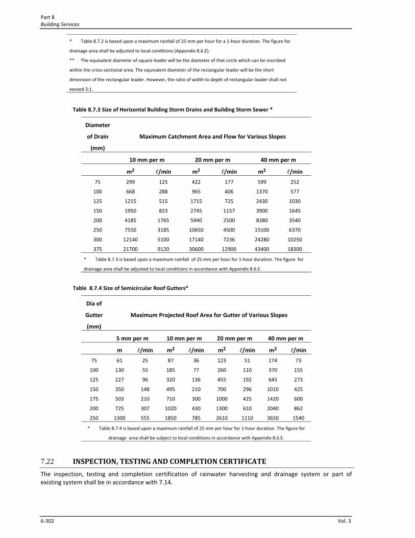
7.21.2 Sizing of Storm Water Drainage Piping The size of building storm drain, storm sewer or any of their horizontal branches shall be based on the maximum catchment area including projected roof or paved area to be drained in accordance with Table 8.7.3.
7.21.3 The size of semi‐circular gutter shall be based on maximum projected roof area according to Table 8.7.4.
Table 8. 7.2 Size of Vertical Leaders*
Size of Leader ** Maximum Projected Roof Area and Flow
(mm) (m2) (l/min)
50
65
75
100
125
150
200
202
367
598
1287
2336
3790
8180
87
155
253
544
986
1602
3450
Part 8 Building Services
6‐302 Vol. 3
* Table 8.7.2 is based upon a maximum rainfall of 25 mm per hour for a 1‐hour duration. The figure for
drainage area shall be adjusted to local conditions (Appendix 8.6.E).
** The equivalent diameter of square leader will be the diameter of that circle which can be inscribed
within the cross‐sectional area. The equivalent diameter of the rectangular leader will be the short
dimension of the rectangular leader. However, the ratio of width to depth of rectangular leader shall not
exceed 3:1.
Table 8.7.3 Size of Horizontal Building Storm Drains and Building Storm Sewer *
Diameter
of Drain
(mm)
Maximum Catchment Area and Flow for Various Slopes
10 mm per m 20 mm per m 40 mm per m
m2 l/min m2 l/min m2 l/min
75
100
125
150
200
250
300
375
299
668
1215
1950
4185
7550
12140
21700
125
288
515
823
1765
3185
5100
9120
422
965
1715
2745
5940
10650
17140
30600
177
406
725
1157
2500
4500
7236
12900
599
1370
2430
3900
8380
15100
24280
43400
252
577
1030
1645
3540
6370
10250
18300
* Table 8.7.3 is based upon a maximum rainfall of 25 mm per hour for 1‐hour duration. The figure for
drainage area shall be adjusted to local conditions in accordance with Appendix 8.6.E.
Table 8.7.4 Size of Semicircular Roof Gutters*
Dia of
Gutter
(mm)
Maximum Projected Roof Area for Gutter of Various Slopes
5 mm per m 10 mm per m 20 mm per m 40 mm per m
m l/min m2 l/min m2 l/min m2 l/min
75
100
125
150
175
200
250
61
130
227
350
503
725
1300
25
55
96
148
210
307
555
87
185
320
495
710
1020
1850
36
77
136
210
300
430
785
123
260
455
700
1000
1300
2610
51
110
192
296
425
610
1110
174
370
645
1010
1420
2040
3650
73
155
273
425
600
862
1540
* Table 8.7.4 is based upon a maximum rainfall of 25 mm per hour for 1‐hour duration. The figure for
drainage area shall be subject to local conditions in accordance with Appendix 8.6.E.
7.22 INSPECTION, TESTING AND COMPLETION CERTIFICATE
The inspection, testing and completion certification of rainwater harvesting and drainage system or part of existing system shall be in accordance with 7.14.
Rainwater Management Chapter 7
Bangladesh National Building Code 2011 6‐303
7.23 GUIDE TO MAINTENANCE
The maintenance of rainwater harvesting and drainage and system shall be in accordance with sec 6.15 of chapter 6.
Related Appendices
Appendix 8.6.B One‐hour Rainfall
Appendix 8.6.E Determining catchments area for a flat surface