rainbarrier continuous insulation guide · museum of the moving image. new york city, ny. 3 what is...
TRANSCRIPT

STANDARDS AND CODE COMPLIANCEINSTALLATION | ATTACHMENT
RAINBARRIER® CONTINUOUS INSULATION GUIDE

2
Why Continuous Insulation? .....................................................................................................................3
Energy Efficiency .........................................................................................................................................4
Non-combustibility ......................................................................................................................................5
Introduction to Owens Corning® Thermafiber® RainBarrier® Continuous Insulation ...................6
Product Options: Owens Corning® Thermafiber® RainBarrier® 45 and RainBarrier® HD .............7
RainBarrier® Installation ............................................................................................................................8Impaling pins ..........................................................................................................................................8
Standard impaling pins .............................................................................................................................8Z-furring with impaling pins (vertical and horizontal) .................................................................................10
Impasse® hangers ................................................................................................................................12Z-furring with Impasse® hangers (vertical and horizontal) ..........................................................................12
Clip & rail systems ..............................................................................................................................14Glass fiber reinforced clips ........................................................................................................................14Thermally isolated galvanized clips ..........................................................................................................15
Cladding options ..................................................................................................................................16Wire ties or flat anchors .........................................................................................................................16Barrel-style anchors ...............................................................................................................................17
Project Spotlight ........................................................................................................................................18
Cover:MUSEUM OF THE MOVING IMAGE
New York City, NY
3
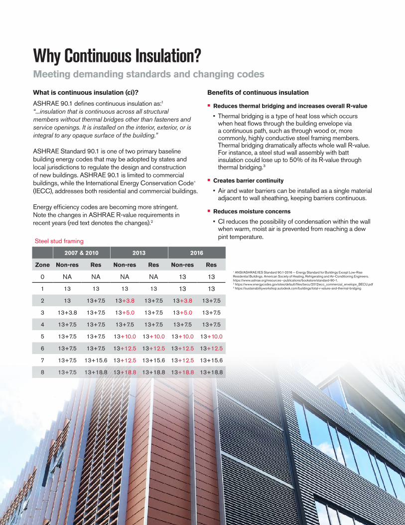
What is continuous insulation (ci)?
ASHRAE 90.1 defines continuous insulation as:1 “...insulation that is continuous across all structuralmembers without thermal bridges other than fasteners and service openings. It is installed on the interior, exterior, or is integral to any opaque surface of the building.”
ASHRAE Standard 90.1 is one of two primary baseline building energy codes that may be adopted by states and local jurisdictions to regulate the design and construction of new buildings. ASHRAE 90.1 is limited to commercial buildings, while the International Energy Conservation Code® (IECC), addresses both residential and commercial buildings.
Energy efficiency codes are becoming more stringent. Note the changes in ASHRAE R-value requirements in recent years (red text denotes the changes).2
1 ANSI/ASHRAE/IES Standard 90.1-2016 -- Energy Standard for Buildings Except Low-Rise Residential Buildings. American Society of Heating, Refrigerating and Air-Conditioning Engineers. https://www.ashrae.org/resources--publications/bookstore/standard-90-1.2 https://www.energycodes.gov/sites/default/files/becu/2012iecc_commercial_envelope_BECU.pdf3 https://sustainabilityworkshop.autodesk.com/buildings/total-r-values-and-thermal-bridging
Benefits of continuous insulation
• Reduces thermal bridging and increases overall R-value
• Thermal bridging is a type of heat loss which occurs when heat flows through the building envelope via a continuous path, such as through wood or, more commonly, highly conductive steel framing members. Thermal bridging dramatically affects whole wall R-value. For instance, a steel stud wall assembly with batt insulation could lose up to 50% of its R-value through thermal bridging.3
• Creates barrier continuity
• Air and water barriers can be installed as a single material adjacent to wall sheathing, keeping barriers continuous.
• Reduces moisture concerns
• CI reduces the possibility of condensation within the wall when warm, moist air is prevented from reaching a dew pint temperature.
Why Continuous Insulation?Meeting demanding standards and changing codes
Steel stud framing
2007 & 2010 2013 2016
Zone Non-res Res Non-res Res Non-res Res
0 NA NA NA NA 13 13
1 13 13 13 13 13 13
2 13 13+7.5 13+3.8 13+7.5 13+3.8 13+7.5
3 13+3.8 13+7.5 13+5.0 13+7.5 13+5.0 13+7.5
4 13+7.5 13+7.5 13+7.5 13+7.5 13+7.5 13+7.5
5 13+7.5 13+7.5 13+10.0 13+10.0 13+10.0 13+10.0
6 13+7.5 13+7.5 13+12.5 13+12.5 13+12.5 13+12.5
7 13+7.5 13+15.6 13+12.5 13+15.6 13+12.5 13+15.6
8 13+7.5 13+18.8 13+18.8 13+18.8 13+18.8 13+18.8

4
The evolution of energy efficiency
We have come a long way with the development of energy efficient buildings.
Paths to code complianceThere are three typical paths to compliance:
1. Prescriptive R-value• Considers R-value of insulation ONLY• Compliance is achieved by installing insulation with
code-prescribed R-value
2. Performance (overall assembly)• Considers:
– U-factors: U-value of assembly (above grade) – C-factors: Thermal conductance (below grade) – F-factors: Slab edge factors
• Compliance is achieved when assembly meets minimum U-value
• Requires calculations or testing to demonstrate compliance but offers greater flexibility in system options
3. Envelope tradeoff• Tightly defined• Allows for trades between various parts of the building
envelope
Energy EfficiencyContributing to sustainable buildings
• ASHRAE Standard 90.1-2007/2010 provides the basic rules
• Tradeoff is implemented in the COMcheck™ software
Going beyond codesMany owners, designers, and contractors feel that the insulation requirements set out in state-adopted codes are not robust enough to truly save energy and reduce greenhouse gas emissions. These owners, designers, and contractors look beyond code initiatives to USGBC’s LEED® rating system1, ASHRAE Standard 189.12 or Architecture 2030.3
Including increased insulation levels in the building envelope can help reach these advanced efficiency goals with a negative marginal cost, generating a positive economic return over the building’s lifecycle.
1900sNo Insulation
In the 1900’s an exterior wall would look pretty much like this:
no insulation.
1940s–1970sLimited Insulation
As we move into the 1940’s and especially during the energy crisis of the 70’s, designers and building owners start to recognize the need for more insulation,
but it’s still used in a limited amount.
Today's Integrated Air/Water/Thermal Assembly
In today’s designed assemblies with the emphasis on energy reduction and sustainable construction we now see systems that incorporate air, water and thermal efficiency all in one assembly.
1 U.S. Green Building Council. https://new.usgbc.org/leed.2 ANSI/ASHRAE/IES/USGBC Standard 189.1-2014, Standard for the Design of High-Performance Green Buildings. American Society of Heating, Refrigerating and Air-Conditioning Engineers. https://www.ashrae.org/resources--publications/bookstore/standard-189-1.3 Architecture 2030. http://architecture2030.org/.References: Architecture 2030. http://architecture2030.org/.ASHRAE Standard 90.1, Energy Standard for Buildings Except Low-Rise Residential Buildings; American Society of Heating, Refrigerating and Air-Conditioning Engineers, Inc.; 1791 Tullie Circle NE, Atlanta, GA 30329. www.ashrae.org International Energy Conservation Code; International Code Council, Inc.; 4051 West Flossmoor Road, Country Club Hills, IL 60478-5795. www.iccsafe.orgASHRAE 189.1, Standard for the Design of High-Performance Green Buildings; American Society of Heating, Refrigerating and Air-Conditioning Engineers, Inc.;U.S. Green Building Council. https://new.usgbc.org/leed.
5
Standards and testing
Non-combustible material is defined as a material that, in the form in which it is used and under the conditions anticipated, will not ignite, burn, support combustion or release flammable vapors when subjected to fire or heat. Materials that are reported as passing ASTM E136, Standard Test Method for Behavior of Materials in a Vertical Tube Furnace at 750°C, shall be considered non-combustible materials.1
ASTM E1361
• Standard Test Method for Behavior of Materials in a Vertical Tube Furnace at 750°C
While it does not duplicate actual building fire exposure conditions, this test method assists in indicating those materials which do not act to aid combustion or add appreciable heat to an ambient fire.
Mineral wool: Non-combustible continuous insulation
Mineral wool products are non-combustible per ASTM E136. Mineral wool will resist flame propagation over the surface of the products.
As a non-combustible material, mineral wool insulation is ideal for assemblies with combustible claddings and/or water-resistant barriers (WRB). When used with other combustible products, mineral wool acts as an aid in passing NFPA 285.
NFPA 2852
• Standard Fire Test Method for Evaluation of Fire Propagation Characteristics of Exterior Non-Load-Bearing Wall Assemblies Containing Combustible Components
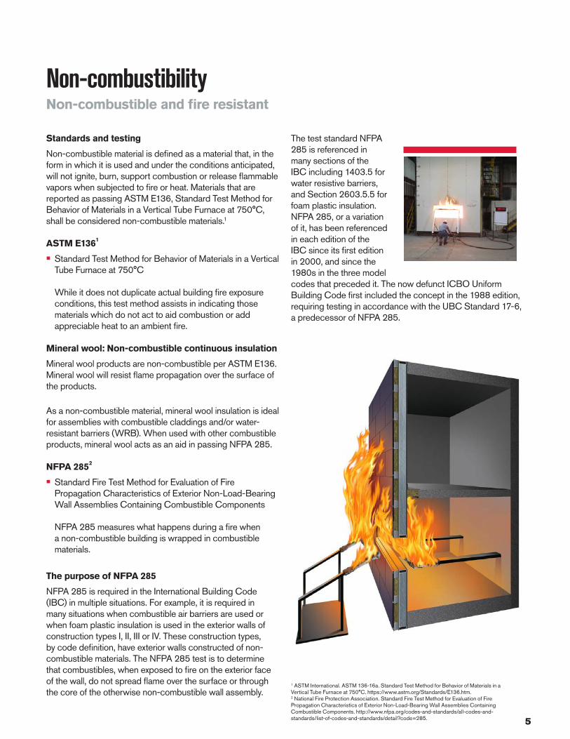
NFPA 285 measures what happens during a fire when a non-combustible building is wrapped in combustible materials.
The purpose of NFPA 285
NFPA 285 is required in the International Building Code (IBC) in multiple situations. For example, it is required in many situations when combustible air barriers are used or when foam plastic insulation is used in the exterior walls of construction types I, II, III or IV. These construction types, by code definition, have exterior walls constructed of non-combustible materials. The NFPA 285 test is to determine that combustibles, when exposed to fire on the exterior face of the wall, do not spread flame over the surface or through the core of the otherwise non-combustible wall assembly.
Non-combustibilityNon-combustible and fire resistant
The test standard NFPA 285 is referenced in many sections of the IBC including 1403.5 for water resistive barriers, and Section 2603.5.5 for foam plastic insulation. NFPA 285, or a variation of it, has been referenced in each edition of the IBC since its first edition in 2000, and since the 1980s in the three model codes that preceded it. The now defunct ICBO Uniform Building Code first included the concept in the 1988 edition, requiring testing in accordance with the UBC Standard 17-6, a predecessor of NFPA 285.
1 ASTM International. ASTM 136-16a. Standard Test Method for Behavior of Materials in a Vertical Tube Furnace at 750°C. https://www.astm.org/Standards/E136.htm.2 National Fire Protection Association. Standard Fire Test Method for Evaluation of Fire Propagation Characteristics of Exterior Non-Load-Bearing Wall Assemblies Containing Combustible Components. http://www.nfpa.org/codes-and-standards/all-codes-and-standards/list-of-codes-and-standards/detail?code=285.

6
Introduction to Owens Corning® Thermafiber® RainBarrier® Continuous InsulationComfort, safety and sustainability
Thermafiber® RainBarrier® continuous insulation (ci) is designed to work with a diverse range of cavity wall or open-joint façade systems. Whatever the specifications of your next project, RainBarrier® mineral wool continuous insulation delivers benefits for:
• Fire and smoke protection: RainBarrier® continuous insulation can withstand temperatures over 2,000°F for more than five hours.
• Sound control: RainBarrier® continuous insulation cuts down on noise between floors, through walls, and from outdoors.
• Thermal comfort: RainBarrier® continuous insulation R-values contribute to the energy efficiency and won’t decrease as the insulation ages.
Standards, Codes Compliance — Thermafiber® RainBarrier® 45 and RainBarrier® HD continuous insulation
Code/Standard RainBarrier® 45 RainBarrier® HD
ASTM C 665 Non-corrosive Type I (unfaced material) Non-corrosive
ASTM C 795 Pass Pass
ASTM C 612 Rain Barrier® 45 Type IA, IB, IVA Rain Barrier® HD Type IA, IB, II, III, IVA
ASTM E 136 Non-combustible as defined per NFPA Standard 220 Non-combustible as defined per NFPA Standard 220
CAN/ULC S114 Complies Complies
ASTM E 96 Unfaced, 50 Perms as tested Unfaced, 50 Perms as tested
ASTM E 84 Flame Spread 0, Smoke Developed 0 Flame Spread 0, Smoke Developed 0
CAN/ULC S 102 Flame Spread 0, Smoke Developed 5 Flame Spread 0, Smoke Developed 5
ASTM C 1104 Absorbs 0.03% by volume Absorbs 0.03% by volume
ASTM C 356 Linear Shrinkage <2% 1200º F (650º C) Linear Shrinkage <2% 1200º F (650º C)
• Installation: RainBarrier® continuous insulation uses no CFCs or HCFCs and installers need minimal PPE during installation.
• Sustainability: Using RainBarrier® continuous insulation contributes to credits in several green building programs such as LEED® and Green Globes®.

7
Product OptionsOwens Corning® Thermafiber® RainBarrier® 45 and RainBarrier® HD
Recycled content option*†:
EPA Choice Fiber (US Government Buildings)..............Minimum 75%Standard Fiber..........................................................................Minimum 70%* Recycled content verified by ICC-ES. † Recycled content options other than standard must be specified at time of order.
Technical data
Tested to ASTM C 518 Tested to ASTM E 84 Unfaced
Actual density“k” @ 75° [24° C]
BTU. In./hr. sq. ft. °F
“R” value per inch of thickness^ Flame Spread Smoke
Developed
Thermafiber® RainBarrier® 45 4.5 pcf 0.23 4.3 0 0
Thermafiber® RainBarrier® HD 6.0 pcf 0.23 4.3 0 0
Acoustical performance
Thermafiber® RainBarrier® 45
Coefficiencies at frequencies per ASTM C 423
Thickness 125 Hz 250Hz 500Hz 1000Hz 2000Hz 4000Hz NRC
1 1/2" 0.22 0.44 0.96 1.06 1.05 1.05 0.90
2" 0.30 0.69 1.08 1.01 1.00 1.03 0.95
3" 0.70 1.07 1.24 1.13 1.07 1.08 1.15
4" 1.03 1.25 1.20 1.05 1.05 1.08 1.15
Thermafiber® RainBarrier® HD
Coefficiencies at frequencies per ASTM C 423
Thickness 125 Hz 250Hz 500Hz 1000Hz 2000Hz 4000Hz NRC
2" 0.36 0.79 1.15 1.04 1.01 1.04 1.00
4" 1.15 1.17 1.18 1.03 1.06 1.08 1.10
6" 1.18 1.01 1.11 1.03 1.06 1.10 1.05
Availablility
Both Thermafiber® RainBarrier® 45 and RainBarrier® HD are available in:
Thickness* Widths** Lengths**
1"–7" 16", 24", 36" 48", 60"
For additional information on green building programs, visit www.owenscorning.com
*Thicknesses are available in ½" increments. ** Custom sizes are available upon request.
^ R=thickness divided by “k”
8
RainBarrier® Installation
Impaling pins
Standard impaling pins
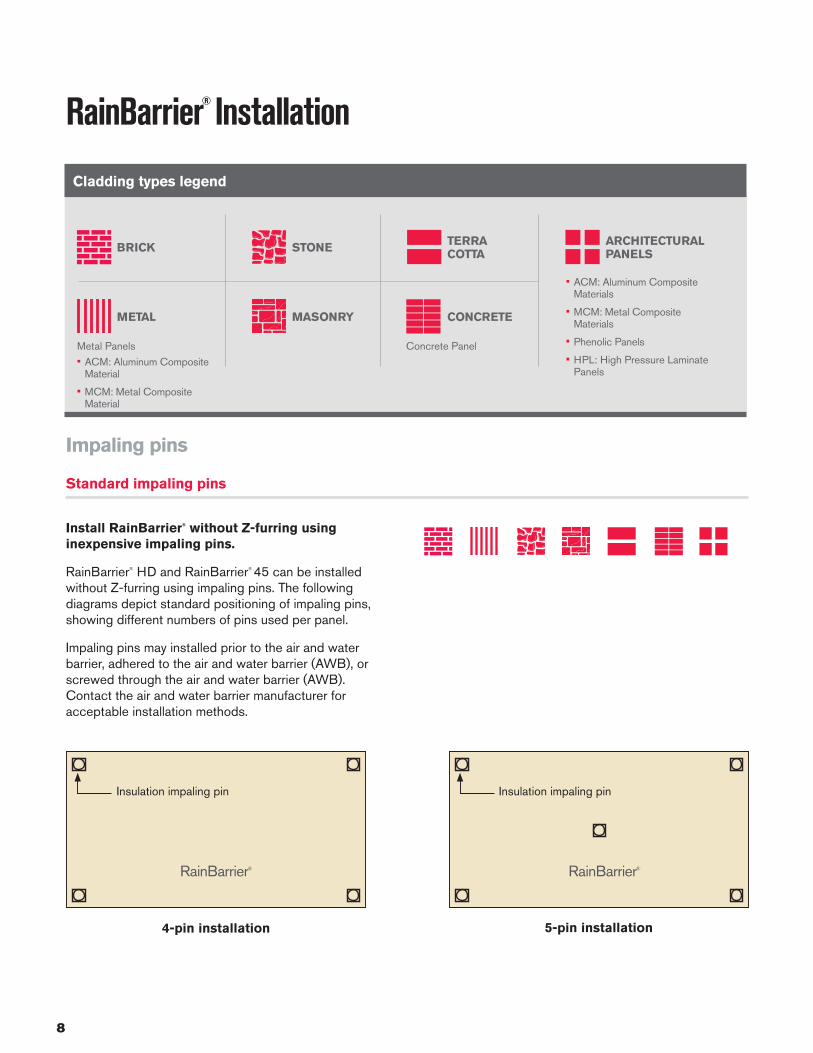
Install RainBarrier® without Z-furring using inexpensive impaling pins.
RainBarrier® HD and RainBarrier® 45 can be installed without Z-furring using impaling pins. The following diagrams depict standard positioning of impaling pins, showing different numbers of pins used per panel.
Impaling pins may installed prior to the air and water barrier, adhered to the air and water barrier (AWB), or screwed through the air and water barrier (AWB). Contact the air and water barrier manufacturer for acceptable installation methods.
RainBarrier®
Insulation impaling pin
4-pin installation
RainBarrier®
Insulation impaling pin
5-pin installation
• ACM: Aluminum Composite Materials
• MCM: Metal Composite Materials
• Phenolic Panels
• HPL: High Pressure Laminate Panels
Concrete Panel
BRICK STONE
MASONRY CONCRETEMETAL
TERRA COTTA
ARCHITECTURAL PANELS
Cladding types legend
• ACM: Aluminum Composite Material
• MCM: Metal Composite Material
Metal Panels

9
Impaling pins/insulation panel Thickness Panel width Panel length
4 1" to 4" 16" 48"
4 1" to 3" 24" 48"
5 4" 24" 48"
6 1" to 4" 36" 48" or 60"
6-pin installation
RainBarrier®
Insulation impaling pin
10
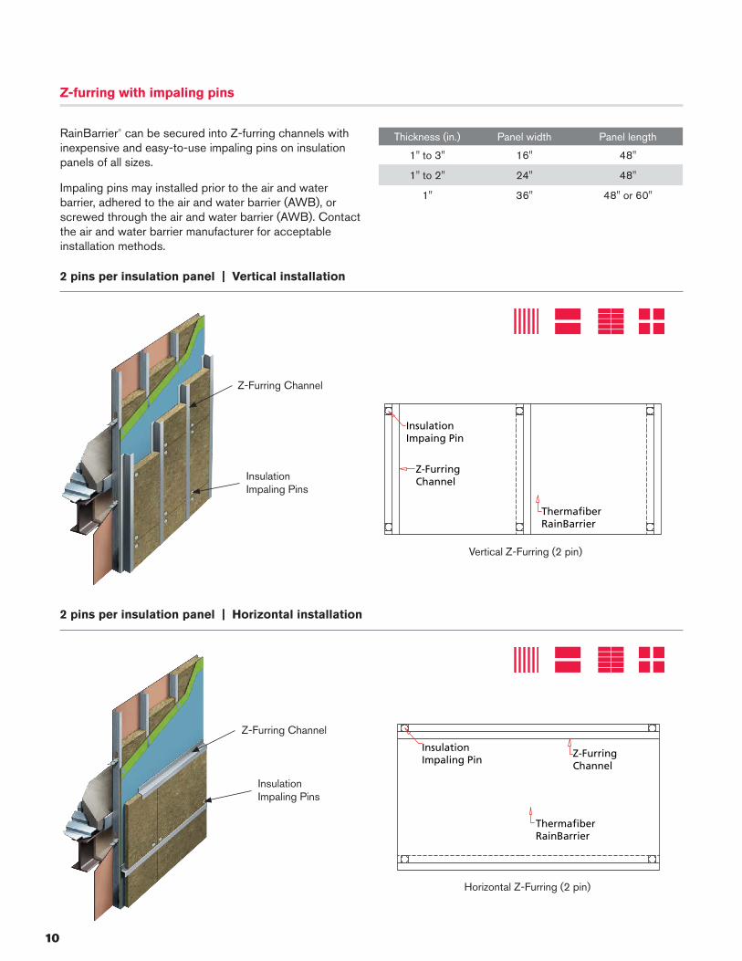
Z-furring with impaling pins
RainBarrier® can be secured into Z-furring channels with inexpensive and easy-to-use impaling pins on insulation panels of all sizes.
Impaling pins may installed prior to the air and water barrier, adhered to the air and water barrier (AWB), or screwed through the air and water barrier (AWB). Contact the air and water barrier manufacturer for acceptable installation methods.
Thickness (in.) Panel width Panel length
1" to 3" 16" 48"
1" to 2" 24" 48"
1" 36" 48" or 60"
2 pins per insulation panel | Vertical installation
2 pins per insulation panel | Horizontal installation
ThermafiberRainBarrier
Z-FurringChannel
InsulationImpaling Pin
ThermafiberRainBarrier
Z-FurringChannel
InsulationImpaing Pin
Vertical Z-Furring (2 pin)
Horizontal Z-Furring (2 pin)
Z-Furring Channel
Insulation Impaling Pins
Z-Furring Channel
Insulation Impaling Pins

11
Z-FurringChannel
ThermafiberRainBarrier
InsulationImpaling Pin
ThermafiberRainBarrier
InsulationImpaling Pin
Z-FurringChannel
Z-furring with impaling pins
Thickness (in.) Panel width Panel length
3½" to 4" 16" 48"
3" to 4" 24" 48"
1½" to 4" 36" 48" or 60"
3 pins per insulation panel | Vertical installation
3 pins per insulation panel | Horizontal installation
Z-Furring Channel
Insulation Impaling Pins
Z-Furring Channel
Insulation Impaling Pins
Vertical Z-Furring (3 pin)
Horizontal Z-Furring (3 pin)
12
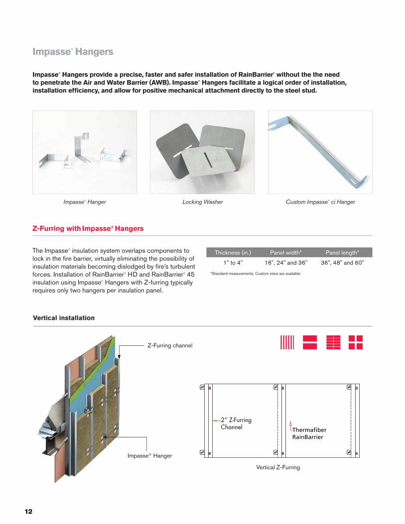
Z-Furring with Impasse® Hangers
The Impasse® insulation system overlaps components to lock in the fire barrier, virtually eliminating the possibility of insulation materials becoming dislodged by fire’s turbulent forces. Installation of RainBarrier® HD and RainBarrier® 45 insulation using Impasse® Hangers with Z-furring typically requires only two hangers per insulation panel.
Thickness (in.) Panel width* Panel length*
1" to 4" 16", 24" and 36" 36", 48" and 60"
*Standard measurements. Custom sizes are available.
Vertical installation
Impasse® Hangers
Impasse® Hangers provide a precise, faster and safer installation of RainBarrier® without the the need to penetrate the Air and Water Barrier (AWB). Impasse® Hangers facilitate a logical order of installation, installation efficiency, and allow for positive mechanical attachment directly to the steel stud.
Z-Furring channel
Impasse® Hanger
2” Z-FurringChannel Thermafiber
RainBarrier
Vertical Z-Furring
Custom Impasse® ci HangerLocking WasherImpasse® Hanger

13
Horizontal installation
Z-Furring Channel
Impasse® Hanger
ThermafiberRainBarrier
2” Z-FurringChannel
Horizontal Z-Furring

14
Glass fiber reinforced clips
This insulated composite clip and rail system is composed of bioresin and recycled fiberglass.
Clip & rail systems
Thermafiber, Inc. is a leader in continuous insulation design by providing installation compatibility with a wide range of RainBarrier® hanging options designed to work with virtually any cladding system in the industry, and accommodate both imaginative designs and demanding specifications.

15
Thermally isolated galvanized clips
These clips minimize contact between the wall and the rainscreen bracket and help reduce thermal bridging at the point of contact for insulation efficiency.
16
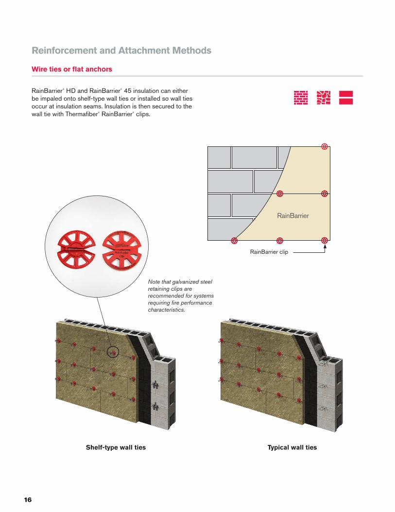
Note that galvanized steel retaining clips are recommended for systems requiring fire performance characteristics.
Reinforcement and Attachment Methods
Wire ties or flat anchors
RainBarrier® HD and RainBarrier® 45 insulation can either be impaled onto shelf-type wall ties or installed so wall ties occur at insulation seams. Insulation is then secured to the wall tie with Thermafiber® RainBarrier® clips.
RainBarrier
RainBarrier clip
Shelf-type wall ties Typical wall ties

17
Barrel-style anchors
Owens Corning® RainBarrier® HD and RainBarrier® 45 insulation can be attached to CMU walls with brick tie wall anchors. Secure insulation by screwing anchor screw with minimum 1½" diameter head to the CMU anchor.
Brick veneer anchor
Brick veneer anchor wall
Brick and mortar with barrel ties
Brick veneer anchor

18
Project SpotlightOwens Corning® Thermafiber® RainBarrier®
Owens Corning® Thermafiber® RainBarrier® continuous insulation can be found in some of the most advanced buildings being constructed today. Here are just a few projects that showcase the comfort, safety and sustainability of RainBarrier® mineral wool insulation.
Commercial buildings
SAN FRANCISCO MUSEUM OF MODERN ART (SF MOMA) EXPANSION San Francisco, California
For a building as striking as the art it houses, the design team turned to Thermafiber® RainBarrier® 45 for continuous insulation. The installation of Thermafiber® products, which have a minimum of 70% recycled content1, helped the building earn LEED® Gold pre-certification.
Occupancy: Museum
BULLITT CENTER Seattle, Washington
This six-story building, featuring RainBarrier® Continuous Insulation, is currently the greenest commercial building in the world. The Bullitt Center is Certified Living by the International Living Future Institute's Living Building Challenge.1
Occupancy: Office
MUSEUM OF THE MOVING IMAGE New York City, New York
This building, featuring Thermafiber® RainBarrier®, carries a LEED® Silver certification and has been honored with the Red Dot Design Award for Architecture + Urban Design (2013) and the Excellence in Design Award from the Public Design Commission of the City of New York (2011)
Occupancy: Museum
1. https://living-future.org/lbc/case-studies/bullitt-center/

19
Institutions
Healthcare Facilities
DISCOVERY HALL, UNIVERSITY OF WASHINGTON, BOTHELL Bothell, Washington
This 74,000 square-foot building features Thermafiber® RainBarrier® 45 Continuous Insulation. The recycled content in Thermafiber® products helped earn this building LEED® Gold Certification.2
SIDNEY & LOIS ESKENAZI HOSPITAL Indianapolis, Indiana
Completed in 2013, Eskenazi Hospital was designed with patient wellness at its center, and features a unique, contemporary façade that combines pre-fabricated concrete, glass and metal. Use of Thermafiber® RainBarrier® contributed to the building’s LEED® Gold Certification.
MUNGER GRADUATE RESIDENCES, UNIVERSITY OF MICHIGAN Ann Arbor, Michigan
Home to more than 600 graduate students, this building features a number of sustainability features, including Thermafiber® RainBarrier® Continuous Insulation. The building is the first residence hall at the University of Michigan to earn LEED® Gold Certification.3
PROMEDICA HEALTH AND WELLNESS CENTER Toledo, Ohio
This $67M health and wellness center consolidates a full spectrum of medical services and offices under one roof. The Center features a terra cotta cladding, and the design team selected Thermafiber® RainBarrier® 45 to help the building meet NFPA 285 requirements.
1 Recycled content certified by ICC-ES. 2 “Happy Earth Day: LEED Gold for Discovery Hall” <https://uwb.edu/news/April-2016/leed>.3 “Munger is first university residence hall to be LEED Gold certified”<https://record.umich.edu/articles/munger-first-university-residence-hall-be-leed-gold-certified>.

20
To learn more about Owens Corning® Thermafiber® RainBarrier® Continuous Insulation, visit www.owenscorning.com.
Pub. No. 10021356. Printed in U.S.A. January 2018. © 2018 Owens Corning. All Rights Reserved. © 2018 Thermafiber, Inc. All Rights Reserved.
LEED® is a registered trademark of U.S. Green Building Council.Green Globes® is a registered trademark of Greed Building Initiative, Inc.UL and the UL logo are trademarks of UL LLC.THERMAFIBER® and THERMAFIBER INSOLUTIONS® are registered trademarks of Thermafiber, Inc.THE PINK PANTHER™ & © 1964-2018 Metro-Goldwyn-Mayer Studios Inc. All rights reserved.Trademarks are the properties of their respective owners.
THERMAFIBER INC. ONE OWENS CORNING PARKWAY TOLEDO, OHIO, USA 43659888-TFIBER1 [834-2371]www.thermafiber.com
1 Recycled content verified by ICC-ES. * Source: Dodge Data & Analytics - Construction.com Spec Rate Report - September 2017.
10 reasons to choose Thermafiber® mineral wool
1. Made from inorganic, non-combustible material per ASTM E136
2. Minimum 70% recycled content2
3. Resists temperatures of over 2,000˚F per ASTM E119
4. Does not require a thermal barrier
5. Flame Spread and Smoke Developed ratings of 0 per ASTM E84
6. Allows vapor transmission providing flexibility in vapor barrier placement
7. Consistent R-values per any thickness regardless of installation temperatures
8. Can be installed at any temperature or weather condition
9. Requires minimal Personal Protective Equipment (PPE) to install
10. Provides excellent thermal, acoustical and fire-resistive properties in one product
Owens Corning® Thermafiber®
The Name In Mineral Wool®
Owens Corning® Thermafiber® mineral wool insulation has brought fire protection, safety and thermal comfort since 1934. Thermafiber, Inc. was acquired by Owens Corning, a leading supplier of building products you can trust.
*