rain impact assessment of advanced thermal … · sd-tr-85-8 rain impact assessment of advanced...
TRANSCRIPT

SD-TR-85-8
Rain Impact Assessment ofAdvanced Thermal Protection System Materials
Phase I Test Results
R. M. COOPER,Materials Sciences Laboratory
Ldboratory OperationsThe Aerospace Corporation 7
El Segundo, CA 90245
5 September 1985
DOEC 10O18~
APPROVED FOR PUBLIC RELEASE;DISTRIBUTION UNLIMITED
Reproduced FromBest Available copy
.-L **.I
s-i Prepared for
SPACE DIVISIONAIR FORCE SYSTEMS COMMAND
FZ Los Angeles Air Force StationP.O0. Box 92960, Worldway Postal Center
Los Angeles, CA- 90009-2960
I 1C% 0 10 Q

This report wva submitted by The Aerospace Corporation, El Segundo, CA
90245, under Contract No. F04701-83-C-0084 with the Space Division, P.O. Box
92960, Worldway Postal Center, Los Angeles, CA 90009-2960. It was reviewed
and approved for 'The Aerospace Corporation by R. W. Fillers, Director,
'4?verials Science3 Laboratory.
Capt Mark D.,Borchardt, SD/YNSA, was the project officer for the Mission-
Oriented Investigation and Experlmenta' on (MOLE) Program.
This report has been reviewed by the Public Affairs Office (PAS) and is
releasable to the National Technical Information Service (NTIS). At NTIS, it
will be available to the general public, including foreign nationals.
This technical report has been reviewed and is approved for publication.
Publication of this report doez not constitute Air Force approval of the
report's findings or conclusions. It is published only for the exchange and
stimulation of ideas.
MARK D. BORCHARDT, Capt, USAF OSEPH HESS, GM-]5MOIE Project Officer Director, AFSTC West Coast OfficeSD/YNSA AFSTC/WCO OL-AB

UNCLASSIFIED
SERCURITY CLASSIFICATION OF TIlS PAGE (Whe, ODu. Ente.d)
REOTDCMNAINPAGE READ INSTRUCTIO14SREPOR DOCMENTTIONBEFORE COMPLETING FORM
1REPORT NUMBER Z2. GOVT ACCESS.3N NO. 3. RECIPIENT'S CATALOG NUMBER
SD-TR-8 5-61 AD 1314. TITLE (end Su.btitle) S. TYPE OF REPORT 6 PERIOD COVERIED
RAIN IMPACT ASSESSMENT OFADVANCED THERMAIL PROTECTION SYSTEMMATERIALS: PHASE I TEST RESULTS 6. PERFORMING ORG. REPORT NUMBER
_________________________________________ TR-0084A( 5935-04 )-27. AUTHOR(o) S. CONTRACT OR GRANT NUMBER(*)
Robert M. Cooper
P04701-83-C-0084S. PERFORMING ORGANIZATION NAME ANO AGGRESS 10. PIOGRAM ELEMENT. PROJECT. TASK
The Aerospace CorporationARAAWKUNT4MESEl Segundo, Calif. 90045
11. CONTROLLING OFFICE NAME AND AGGRESS IS. REPORT DATE
Space Division ' 5 September 1985Los Angeles Air Force Station 13. NUMUIER OFPAGESLos Angeles, Calif. 90009-2960 67
14. MONITORING AGENCY NAME A ADORESS(i! dillfe,e from. Co..trolling Ohic.) IS.. SECUJRITY CLASS. (at this report)
Unclassified15a DECLASSIPI CATION/ODOWNGRAOIG
SCHEDULE
IS. DISTRIBUTION STATEMENT (of this Report)
Approved for public release; distribution unlimited.
17. DISTRIBUTION STATEMENT (of Ihe ahstrect ... temstil Block 20. It dff~rwt inas Repot)
1S. SUPPLEMENTARY NOTES
I9. KEY WORDS (Contirnue oi rec.,se side it ftsce.e d Idenity by block auiber)
Rain erosionRain impactThermal Protection System (TPS)Tiles
20. ABSTRACT rConrInu* . .. * aids.,Id It necesarywed identify by block n.Iavber)
A rain impact test program, conducted jonintly with NASA and AFWAL/UDRI tostudy the durability of advanced thermal protection system (TPS) materialsunder exposure to rain conditions typical of flight,,has been under waysince FY 83. The first test series was conducted in'February 1984 at theAFWAL Materials Laboratory Mach 1.2 Rain Erosion Test Facility.- - Damiagethreshold levels were bracketed or upper limits established for the
-PARs UNCLASSIFIED
SECURITY CLASSIFICATION Oil THIS PAGE (10hon Del. En-W,.G

UNCLASSIFIEDSItuMITY CLASSIFICATION OF TH4S PAQVIrft Does BoIntet.IS. KILY WOROS (CeotjmjeE)
10. AISTRACT (Coair, d)
rigid 'TPS materials. The borosilicate glass-coated TPS failed by flexure ofthe coating, and a ro, Ah correlation of rain impact resistance with thecompressive modulus of the tile substrate material was' found. Thedurability of the bare tile material was not substantially increased by the
use of a SiC coating infiltrated and sintered in the surface layer. Thetesting technique used with the flexible cloth class of TPS entailed
difficulties which precluded the acquisition of valid test daLa, andalternative approaches for obtaining the desired data are being explored.
/
UNCLASS IF TEDSIECURITY CLASSIFICATION OF TMIS PAG~ 0hM. Dl& InMI.d)
" U (~ O " ' . ) V. J i ... ... VM

PREFACE
The data presented here are the result of a joint NASA/AFWAL-University
of Dayton Research Institute/Aerospace Corporation effort to investigate the
rain impact resistance of advanced thermal protection system (TPS) designs.
Chief contributors are:
NASA Ames Research Center
H. Goldstein
D. Leiser
P. Sawko
University of Dayton Research Institute (UDRI)
C. J. Hurley
Thanks are also due tO Timothy Courney, University of Dayton Research
Institute, for performing the tests in the AFNAL Materials Laboratory Rain
Erosion Test Facility; to Noal Tracy, of the Universal Technology Corp., for
NDT of test articles; and to John Zelgenhagen, University of Dayton Research
Institute, for pre and post te-t photography of the test articles. Mention
must also be made of helpful discussions and tile property data from Mr. Dave
Musteliar,' Rockwell International, and tile property data from Mr. Ronald
Banas, Lockheed Missiles and Space Co. Sound speed measurements on FRCI-20-12
and LI-900 tile samples were carried out by Mr. John R. Linn, of The Aerospace
Corporation, Materials Sciences Laboratory.

CONTENTS'
I. ITS ROCIOA....................................................... 17
B11 AP PCH. Ma.erial..scri..i.......................... 17
C. Phase I Test Matrix.o............. *.......................... 24
D. Test Fhilosophy......o..............o........oo.... .. .. 28
V. PHASE I TEST RESULTS..o... ..... o... o..................... ........ 31
B. Rigid TPS Test Results...0..... 00.... ... 0.*.... .. 0.. 31
C., Discussion... ... o.00.0000.. ... . .. 0000-.4000 *... 0-.0...** 59
VI. CONCLUSIONS AND RECOKMENDATIONS...... ....... o. *.o. . .. ... 0 . .. 65
REFERENCES.*... o.....................o ..... o........ -.... 67
APPENDIX
A. Theoretical Considerations... . . .. . .. .... * * . . . . . .. o-* . .. 69
Accesion ForNTIS CRA&I
oneC iAB E
B y
IQUAIJ ryD-
3

FIG:RES
1. 90* Impact Angle Specimen- Configuration 2........................ 18
2. 90' Sample Cover Plate............................................. 19
3. Sample Ho1der .... , ................... 20
4. 450 Impact Angle Specimen -Configuration 6....................... 21
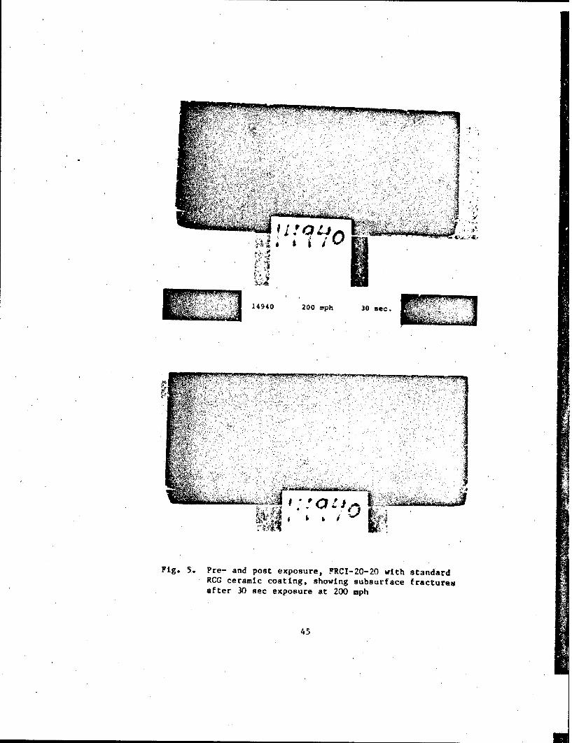
5. Pre- and Post Exposure, FRCI-20-20 With StandardRCG Ceramic Coating, Showing Subsurface Fracture After30 sec Exposure at 200 mph..................................... ... 45
6. Pre- and Post Exposure, FRCI-20-20 With StandardRCG Ceramic Coating, Showvlg Damage After3sec Exposure at 300 mph....................................... 6
7. Pre- and Post Exposure, LI-2200 With StandardRCG CAeramic Coating, Showing Star-shaped Crack After60 sec Exposure at 150 mph ......................................... 47
8. Pre- and Post Exposure, LI-2200 With StandardRCG Ceramic Coating, Showing Damage After30 sec Exposure at 200 mph .......................................... 48
9. Pre- and Post Exposure, FRCI-20-12 With StandardRCG Ceramic Coating, Showing Surface Cracks andLoss of Coating Segment After 24 secExposure at 150 mph...... ........ so..... 49
10. Pre- and Post Exposure, FRCI-20-12 With Twice StandardThickness RCG Ceramic Coating, Showing One SubsurfaceFracture After 60 sec Exposure at 200 mph. ......................... 51
11. Pre- and Post Exposure, LI-900 With StandardRCC Ceramic Coating, Showing Ceramic Coating Lossand Tile Erosion After 18 sec Exposure at 150 mph .................. 52
12. Pre- and Post Exposure, Uncoated FRCI-20-20,Showing Cratering After 6 sec Exposure at 150 mph.................. 53
b 213. Pre- and Post Exposure, FRCI-40-20 With 0.046 lb/ft
SiC (CVD) Coating, Showing Cratering After30 sec Exposure at 150 mph ............................ ....... 55
i

FIGURES (Continued)
14. Pre- and Post Exposure, LI-2200 With 0.023 lb/ft2
SiC (CVD) Coating, Showing Cratering cnd TileErosion After 6 sec Exposure at 150 mph.... ................ 56
15, Pre- and Post Exposure, LI-2200 With 0.023 lb/ft2
SiC (CVD) Coating, Showing Coating Loss and TileErosion After. 30 sec at 200 mph.**..,,,,,***............... 58
I...6

TABLES
1. Advanced Flexible Ceramic Blanket TPS Materials Description#..,,, 23
2. Rigid Ceramic Fiber Insulation.**..**** ........ . ......... 25
3. Phase I Test Matrix (Angle of Incidence Normal to Surf ace).*....... 26
4. Phase I Test Results Summary ....o.eoo.*.**.**...................... 32
5. Damage Threshold Levels*9.... ........ ... .. i....... 44
6. Typical Physical and Mechanical Properties.o......... ...os ... ..**9 62
7

1. INTRODUCTION
Rain and ice impact damage has been a continuing concern in the develop-
ment of atmospheric entry vehicles. Materials that provide thermal protection
at hypersonic 'speeds are not necessarily resistant to rain and ice impact at
supersonic and subsonic speeds. In addition, the relationship among material
properties, environmental parameters, and flight performance has not been ade-
quately established. For future manned and unmanned 'ifting entry vehicles,
the rain and ice erosion performance of candidate heat shield materials must
be evaluated and the mechanism of the erosion process studied. This program
addresses the issue of heat shield material performance and is thus intended
to contribute to the understanding of the basic physical processes involved.
The development of advanced, reusable military spaceflight systems,
advanced space transportation vehicles, and advanced hypersonic cruise
vehicles includes the consideration of three options for space vehicle con-
struction: (1) cold or warm structures with operating temperatures of the
structural materials limited to less than 700*F by an external thermal protec-
tion system; (2) metallic hot structures, operating at structural temperatures
on the order of 2000*F with no external thermal protection system (TPS); and
(3) carbon-carbon hot aeroshell structures, operating at temperatures on the
order of 3500F.
The current space shuttle system was designed for launch in fair weather
only. Initial flight experience has shown that rain and hail impact damage to
the orbiter external iriulation heat shield on the launch pad and during ferry
flight are significant operational concerns for the reusable surface insula-
tion (RSI) system. An RSI that has greater rain resistance for use on the
current orbiters and future advanced space transportation systems will result
in much more durable and cost-effective vehicles. Therefore, new 'rigid and
flexible ceramic heat shield materials being developed by NASA have improved
rain resistance among their development goals.
9

Advanced military sPacef light and other hypersonic' cruise vehicle system
requremets include all-weather operation, particularly with
regard to
launchOn-demand, airborne loiter, and land- ndead~ crillteei
a r-eed to evaluate the rain and hail impact eoinadcaatr~iso
h
candidate surface materials to be employed in the various
design options, so
that realistic and valid specifications and limitations can be applied to each
concept. Of concern are advanced TPS materials, hot structure
surface coat-
ings,'and advanced carbon-carbon materials.
10
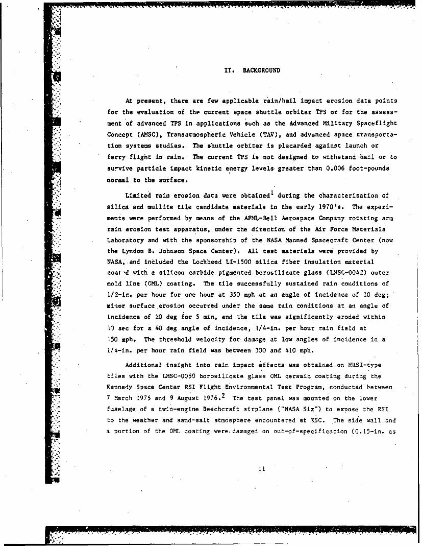
II. BACKGROUND
At present, there are few applicable rain/hail impact erosion data points
for the evaluation of the current space shuttle orbiter TPS or for the assess-
ment of advanced TPS in applications such as the Advanced Military Spaceflight
Concept (AMSC), Transatmospheric Vehicle (TAV), and advanced space transporta-
tion systems studies. The shuttle orbiter'is placarded against launch or
ferry flight in rain. The current TPS is not designed to withstand hail or to
survive particle impact kinetic energy levels- greater than 0.006 foot-pounds
normal to the surface.
Limited rain erosion data were obtained1 during the characterization of
silica and mullite tile candidate materials in the early 1970',s. The experi-
ments were performed by means of the AFML-Bell Aerospace Company rotating arm
rain erosion test apparatus, under the direction of the Air Force Materials
Laboratory and with the sponsorship of the NASA Manned Spacecraft Center (now
the Lyndon B. Johnson Space Center). All test materials were provided by
NASA, and included the Lockheed LI-1500 silica fiber insulation material
coa-d with a silicon carbide pigmented borosilicate glass (LMSC-0042) outer
mold line (CML) coating. The tile successfully sustained rain couditions of
1/2-ir.. per hour for one hour at 350 mph at an angle of incidence of 10 deg;
minor surface erosion occurred under the same rain conditions at an angle of
incidence of 20 deg for 5 min, and the tile was significantly eroded within
..0 sec for a 40 deg angle of incidence, 1/4-in. per hour rain field at
',50 mph. The threshold velocity for damage at low angles of incidence in a
1/4-in, per hour rain field was between 300 and 410 mph.
Additional insight into rain impact effects was obtained on HRSI-type
tiles with the LMSC-0050 borosillcate glass OML ceramic coating during the
Kennedy Space Center RSI Flight Environmental Test Program, conducted between
7 March 1975 and 9 August 1976.2 The test panel was mounted on the lower
fuselage of a twin-engine Beechcraft airplane ("NASA Six") to exDose the RSI
to the weather and sand-salt atmosphere encountered at KSC. The side wall and
a portion of the OML coating were damaged on out-of-specification (0.15-in. as
11"W"-p. i

opposed to the 0.015-in. specification value) forward facing steps presented
by the lead tiles in the arrays while on a flight through light-to-moderate
showers at an average air speed of 144 mph (125 knots) and a maximum speed of
184 mph (160 knots) during a 2.1 hour flight. Flight altitude was on the
order of 10 kfeet.
Experience with shut tle orbiter flights has demonstrated that even severe
hail impact damage can be suitained over certain portions of the vehicle TPS
where entry heating loads are net high, e.g., fuselage sidewalls, without
significant overheating of the underlying substructure. Likewise, localized
but severe launch debris impact damage to portions of the lower surface tiles
where heat loads are fairly high, such as on the nose landing gear door and on
the body flap, and the complete loss of the outer mold line (OML) ceramic
coating plus a portion of underlying tile material of six high temperature
reusable surface insulation (HRSI) tiles along the right hand chine due 'to'on-
orbit ice cracking, did not result in significant substructure overtempera-
tures during entry even though incipient failure of the RSI did occur.
However, where portions of the OMS pod forward sec.-i PS have been lost due
to pre-launch hail damage or during launch and ascent, entry heating resulted
in graphite-epoxy honeycomb sandwich panel substructure damage of varying
degrees of severity. In the most severe case, that due to launch debris
impact damage to the lefthand pod during STS-9, it was found necessary to
replace a panel of the forward section substructure. Whereas this OMS pod
damage has not resulted in shuttle orbiter safety of flight issues because of
the localized character of the damage and the absence of critical components
behind the damage site, entry heat loads in regions of higher heating couldbecome a safety-of-flight issue in the presence of such TPS damage and loss.The complete loss of the OML coating from two or more adjacenGt lower surface
tiles in critical areas such as aft of the nose cap, at the wing tips anti
outboard elevon, and on the body flap would be considered very serious, with
probable safety-of-flight implications for any entry trajectory. For military
operations, the need for TPS and possible substructure replacement would have
*very undesirable, if not unacceptable, impact on turnaround time between
missions.
i 12
I

Concern regarding ice impact on the TPS arose following the first of the
orbital flight test launches because of the damage sustained from launch
debris impact, including ice from the cryogenic external tank (ET). Consider-
able progress has been made in eliminating debris sources, in large measure
because of a concerted effort by the debris damage team. This activity has
been paralleled by an on-going ice impact test program 3 which is evaluating
the damage resistance of a broad range of T'S materials. The preliminary
phase and Phases I through 3 of the program have been completed, providing
data on the relative performance of lower surface HRSI/LI-900, LI-2200, rein-
forced carbon-caiuon (RCC), fibrous*'refractory composite insulation (FRCI),
and advanced flexible reusable surface insulation (AFRSI) materials, as well
as a class of "enhanced" coatings.
The program results demonstrated the importance of projectile breakup as
an energy dissipation mechanism, and, in particular, showed that steel ball
drop test data'are not a valid basis for estimating ice impact response
(because of the lack of the projectile breakup mechanism). The hard ice
projectiles used in the test program are considered a good simulation for the
hard ice found on' some areas of the ET ogive; frozen clear water droplets
(icelets) have also been observed on the ET ogive. However, acreage sheet ice
found on the ET ogive tends to be "softer" ice which has better breakup
characteristics than the hard ice.
The Phase 2 test results indicate that the flexible blanket material
experiences gouging to about the same extent as the LI-900 tile damage under
similar ice impact conditions. The extrapolation of this ice impact response
data to rain impact response prediction is uncertain for several reasons,
including, the question of how to properly account for the influence of projec-
tile (raindrop) breakup, as well as possible difference in angle of incidence
between the ET ice impact scenario and the laur '.-through-rain scenario.
Very recently, limited single drop and multiple-drop rain impact testing
of current TPS materials has been performed by investigators at Rockwell
International (RI). Of particular interest is the performance of the HRSI
(LI-900), AFRSI, and LRSI materials under conditions simulating a launch
13

through fog and drizzle. Additional testing was carried out during FY 84
under an internal R and D crogram.
To initiate the development of a suitable data base summarizing the
expected performance of advanced TPS materials of interest to the AMSC and
future STS programs under rain impact conditions, including conditions
relating to ferry flight or loiterIng, an informal joint test program with
AFWAL/UDRI, NASA Ames Research Center, and AFSTC/Aerospace is in progress.
The cooperative effort draws upon the extensive background, experience, and
experimental capabilities in the impact erosion technology area that have been
developed within the Air Force Wright Aeronautical Laboratories by the
Materials Laboratory and UDRI Aerospace Vehicle Coatings Group (C. Hurley).
Advanced TPS materials that are being studied by NASA Ames (H. Goldstein)
provide the major portion of the rain erosion test matrix. Laboratory examin-
ation of the post-test condition of the test articles will be performed
jointly by AFWAL/UDRI and The Aerospace Corporation as part of the Laboratory
Operations MOlE program.
14
III. APPROACH
The broad objectives of the test program are to establish rain impact
damage threshold conditions for advanced TPS materials and to collect data for
future use in developing empirical and analytical damage prediction models.
An attempt will also be made to relate the rain impact damage to the expected
reduction in thermal protection provided by the damaged TPS to typical lifting
entry vehicle substructures.
Two classes of TPS materials were evaluated in Phase I of the program:
(1) flexible ceramic insulation blanket materials, and (2) rigid reusable
surface insulation (RSI) materials. The rigid RSI materials were examined
both with and without the reaction cured glass (RCG) ceramic coatings needed
to provide t.e surface optical properties necessary for space vehicle orbital
and entry functions as well as to provide moisture protection for the tile.
One set of samples included a developmental tile coating formed by chemical
vapor deposition of SiC in the tile surface. The response of carbon-carbon
cowposite material such as currently used for nose cap and wing leading edge
and proposed for aeroshell construction of future STS configurations will be
studied later in the test program. The performance of multi-wall metallic TPS
designs also is of interest and an effort will be made to. acquire and test
prototype test articles later in the program.,
15

IV. TEST PROGRAM
A. FACILITIES
The rain erosion experimentation is being carried out in the AFWAL Mach
1.2 Rain Erosion Test Facility (described in Ref. 4) using a calibrated 1-in.
per hour simulated rainfall of 2.0 mm dia. (avg.) drops. During the Phase I
tests, the 90 deg impact angle specimen-configuration 2 (Figure 1) was used,
with the standard titanium cover plate (Figure 2) having a 1.87 by 0.8 inch
exposure area, held in the standard stainless steel sample holder (Figure 3),
which is bolted to the test facility whirling arm. One test series was also
carried out using the 45 deg 1-pact angle specimen geometry (configuration 6),
shown in Figure 4.
B. TPS MATERIAL DESCRIPTION
The Phase I test matrix included two general classes of TPS: advanced
flexible ceramic blanket insulation and rigid ceramic fiber insulation
materials. Other classes, such as carbon-carbon (RCC/ACC) and metallic TPS
will be added as theybecome available.
1. Advanced Flexible Ceramic Blanket Insulation
The flexible blanket configuration parameters are:
a. Outer Mold Line (OML) fabric material, thickness, and sizing
b. Internal insulation material, thickness and density
c. O1L thread material, thickness, sizing, and stitching patterns
The ba.1ine flexible blanket material is the AFRSI initially used on the
OMS pods of shuttle orbiter OV-099 and on the upper surfaces of oV-103. The
blanket typically consists of the Type 2, heavy, 0.027-in. Astroquartz 570
silica OML cloth layer stitched over a nominal 0.045-in. thick (Class 1)
microquartz Q-felt internal insulation material with 0.020-in. dia. Teflon-
sized silica thread. The blankets are waterproofed with Dow Corning Z 6070
Silane, the same waterproofing agent used in the rigid TPS on shuttle orbiter
vehicles.
17

4 1 17 i -247 - RIM -w7 w-r 7, 7, -
1.000 in. +.0
-00.062
0.50 n.+0. 0000.50 i. 0.062
ALL DIMENSIONS IN INCHES
Fig. 1. 900 Impact Angle Specimen -Configuration 2
18

CCD
000
szo -I
194

II
L.s Ua1 .
Ii. PrC4
w~ -n
en N a
'206

I
+0.0001.000 in. -0.005I!
+0.000 i0. 656 in -0.010
o. 125 Wt.. 0.010
45
ALL DIMENSIONS IN INCHES
Fig. 4. 450 Impact Angle Specimen - Configuration 6
21

In Phase I of this program, only the OML cloth materials were tested.
Because size effects are critical in the performance of flexible ceramic
insulation blankets, sample holder size limitations make it doubtful that a
valid simulation of a complete blanket is possible and results could be
misleading. It was hoped that testing one element of the flexible ceramic
insulation blanket, such as tie OML cloth layer would permit the candidate
materials to be compared. A common backing material, the felt RSI (FRSI)
material, was used as the substrate material backing the candidate test cloth
materials.
The baseline AFRSI cloth material was heat cleaned and waterproofed and
was tested as is (i.e., with no additional coating); with a Rockwell ceramic
coating identified as the C-9 coating; and with a NASA Ames RC ceramic coating
(ACC). The Rockwell C-9 coating is a high purity formulation of deionizedLudox (MB0115-011) and ground silica (MB0115-036) applied after a primer orpre-coat of deionized Ludox and isopropyl alcohol' has been used to deactivate
the waterproofing and provide a base coat for improved adhesion to the OML
cloth layer.
The experimental OML cloth fabric materials to be studied were Nextel-312
(900 denier) fabric, manufactured from aluminoborosilicate fibers by 3M
Corporation, and Nicalon, manufactured by Nippon Carbon, a silicon carbide
fabric that recently became available. The Nextel-312 and Nicalon'OML cloth
layers were heat cleaned and waterproofed. The flexible ceramic blanket
materials are described in Table 1.
2. Rigid Ceramic Fiber Insulation
The rigid ceramic fiber insulation material configuration parameters
*-are: (1) tile substrate matetials and thickness, (2) OML ceramic coating
materials and thickness, and (3) waterproofing (Dow Corning Z-6070 Silane).
The baseline rigid ceramic fiber insulation material in this program is
FRCI-20-20, a second generation tile material that has shown considerable
resistance to crack propagation. At the present time, FRCI-20-12 has been
flight qualified and is being used on shuttle orbiter vehicle-103. The FRCI
material is a composite of two ceramic fibers plus a small percentage of
silicon carbide, which is added as an opacifier and emittance agent to provide
- .

lower thermal conductivity and improved optical properties. In the FRCI
material designation, the first number is the percent of aluminoborosilicate
fiber, and the remainder is the same silica fiber (microquartz) that is used
in the first generation RSI. The second number is the tile density in pounds
per cubic foot. For comparison, current shuttle orbiter tile materials,
fabricated from the pure silica fiber (microquartz) only, were tested. The
material designations are LI-900 (9 pounds per cubic foot density) and LI-2200
(22 pounds per cubic foot density). The FRCI-20-20, FRCI-20-12, LI-2200, and
LI-900 tile materials were exposed to rain impact with and without the base-
line doped borosilicate reaction cured glass (RCG) OML ceramic coating. In
addition, chemical vapor deposited (CVD) silicon carbide (SiC) coatings of
2.5 weight percent and 5.0 weigh: percent were applied to LI-2200, FRCI-40-20,
FPCI-60-20, and alumina-enhanced thermal barrier (AETB) material, AETB-40-20,
j test samples. AETB material is an experimental advanced rigid tile material
being developed by NASA Ames Research Center. With two exceptions, all test
samples were waterproofed following current fabrication procedures.
Table 1. Advanced Flexible Ceramic BlanketTPS Materials Description
OML Cloth OML Cloth CoatingSource Material Thickness, mil Material
Rockwell Type 2, heavy 27 NoneProduction Line Astroquartz 570 RCC
ACC
Type 1, light 10 NoneAstroquartz 593 RCC
ACC
3M/Ames Nextel-312, heavy NoneResearch Material (900 denier) ACCI
Dow Corning/Ames Nicalin SiC None
Research Material ACC
RCC - Rockwell Ceramic Coating (C-9) High Purity ludox and silica.I'ACC - Ames Research Center Ceramic Coating.
.A 23
I

.1
One standard thickness (0.015 in.) was used on all RCG coated test
samples with the exception of the FRCI-20-12 material, which also included
samples with twice the standard RCG coating, thickness. Sets of test articles
with a minimum of six test samples are designated "nominal" sets. In addi-
tion, four of the more readily available tile material configurations were
used in preliminary scoring test runs to calibrate the test rain field and
establish che order of magnitude of the velocities just producing damage inthe four different tile substrate materials. These sets contained more than
the minimum number of six samples, and are designated as "calibration" sets.
The rigid tile materials are described in Table 2.
C. PHASE I TEST MATRIX
The prioritized test matrix for the Phase I experiments is given in
Table 3. The first priority for the rigid tile materials was the baseline
FRCI-20-20, which was expected to show the best performance, based upon
current knowledge of materials behavior. If this material did not surviva at
the lowest calibrated test speed of the facility, there was no point in
testing the other coated rigid tile materials listed in the first group,
because they were believed to be weaker than the baseline material. The four
cloth materials and the unwaterproofed water-filled FRCI-20-20 samples
followed as shown. Testing of the uncoated rigid tile samples depended upon
the performance of the coated materials. The lowest speed of interest in
seeking the damage threshold level for any material has been selected to be
100 mph, although a higher lower limit (e.g., 120 or 130 mph) would have been
acceptable. The rationale for the initial test speed selection is given in
the following paragraphs.
S-. 1. Advanced Flexible Ceramic Blanket Insulation
. Neither empirical extrapolation of existing data nor analytical modelling
approaches were available for predicting the damage threshold levels for these
materials. Accordingly, estimates of the likely damage threshold velocities
for the advanced flexible ceramic blanket insulation materials had large
uncertainties because of the lack of knowledge or data on rain impact effects
on such materials. The results of Phase 2 of the Ice Impact Testing Program
N 24
7 ,

1:
v2
2 c Z
3 3r
6 6 .'t T 6
14, n, 1
Z- Z z
tw-
-l t
19 ! = U-P.

• . = .. + "- = * . .
• -.,, + 'j :"."2-..
-- a ---- '47=+ + +. -- + +-* , 7 4 i ' '
_ .. .'42277,7 _
I&.4 0 - -++.++.+ o m m + + - 2 -2 2 '4I.-. C++* + .U I " i
U,'12. CI ' ' , 4 4-'
2. . 2_2 . . . '4. . ... 22 2_
"" - - 2 44C"Ci 2 4 4 4 ,,d 4 2
_.+. 7 ' ' 4 C 4 7 7 ! ' . 4 ' '* 7 7.7 7 -- I .7 C
+ 1 a
o K1+
",,'..'< 2.- p I
+'S-'4:

(Ref. 3) indicated that the AFRSI blanket material damage was similar to that
for the LI-900-tiles tested during Phase 1. Since all materials tested were
significantly damaged urder the prescribed test conditions, damage threshold
levels were not available.
Recent RI results indicate that AFRSI performance was superior to that of
LRSI, which uses the LI-900 tile material with a 10 mil white 0036 ceramic OML
coating, when exposed to drizzle-type conditions (average drop size 0.7 mm
dia.). No data were available for the Nextel-312 or Nicalon SiC cloth
materials. On the basis of available data, an initial test speed of 300 mph
was selected.
2. Rigid Ceramic Fiber Insulation
The data from Fl provided some insight into the probable damage mechanism
and a basis for extrapolation to the normal incidence, 2.0 me dia. drop size
case of interest here. Local flexura failure of the RCG OML ceramic coating
in the vicinity of a water drop impact at a speed of 200 mph appeared to be a
reasonable expectation for the coated FRCI-20-20 material. This speed is
somewhat higher than the zeroth order ex-rapolation to 120 mph which can be
made from the 1972 data (Ref. 1) mentioned in Section II, where a less dense
(LI-1500, 15 pounds per cubic foot density) tile material with a type-0042
borosilicate glass coating of unreported thickness was used. The 120 mph is
the velocity component normal to the surface from the 20 deg angle of
incidence, 1"in. per hour rainfall data in Ref. 1, where only slight erosion
of the coated LI-1500 test article was found. The actual damage threshold
velocity for nornal impact was expected to be somewhat less than 120 mph, o~n
the basis of observations given in the literature (see Ref. 5 for an extensive
list of references). For example, lessdamage occurred in infrared
transmitting materials under shallower angles of impact than in the normal
impact case with the same normal component of velocity. 6 Likewise, the KSC
flight through light-to-moderate rain resulted in substantial side wall damage
with an average flIght speed of 144 mph (125 knots) and a maximum speed of 184
mph (160 knots), i.e., on the same order as indicated by the Ref. 1 data.
27

The higher density, stronger FRCI-20-20 was expected tc have a higher
damage threshold level. Experience at UDRI obtained over a number of years
with the rain erosion test apparatus indicates that the flight test situation
in which the forward facing step, was present at the damage site resulted in a
more severe condition than would be produced under the 90 deg normal impact
test configuration; this suggests a higher damage threshold here. This is
because of trapping or channelling of water and energy into a "corner", with
no other place to go, in the KSC fligfit situation.
Raindrop deformation and travel after impact transfers three or four
times as much energy as is imparted on initial impact. The variation of
damage with angle of incidence is therefore more complicated than a simple
dependence on the normal component of the drop velocity. The empirical
extrapolation of experimental data as well as the interpretation of the flight
test data must be understood to contain some level of risk.
D. TEST PHILOSOPHY
A number of performance characteristics must be established to determine
the relative ranking of candidate advanced TPS materials under rain impact
conditions. These characteristics include single mission failure levels,
single mission replacement levels, and reduction in mission lifetime. Single
mission failure levels are those conditions of velocity and rain rate tor
which TPS rain impact damage results in significant or catastrophic vehicle
substructure damage caused by entry heating effects. Single mission replace-
ment levels are those conditions under which TPS rain impact,damage during
launch will require TPS replacement before the next flight. This performance
characteristic could be critical to mission control decisions regarding launch
under ,adverse weather conditions and could define the space system launch-on-
demand capability. Reduced TPS mission lifetime caused by rain impact during
launch also affects overall launch-on-demand, airborne loiter, and land-on-
demand capability.
While determination of the single mission failure and replacement levels
appears to De reasonably straightforward, reduction in TPS mission lifetime
may be more difficult to interpret, because the effects of entry heat cycling
28
and rewaterproofing operations between flights, in some cases, may result in
synergistic effects on rain impact response and damage accumulation.
It is beyond the snope of this preliminary program to address all these
performance issues for the selected test materials. The test philosophy
adopted here is to develop as much data as possible regarding damage
mechanisms, levels of performance, and material response to support further
analytical and experimental studies of, TPS resistance to rain impact.
The 90 deg impact angle specimen, configuration 2 (see Figure 1), of the
AFWAL Mach 1.2 Rain Erosion Test Facility was selected for 'Phase I testing,
for several reasons. The configuration 2 test sample holder permits specimens
with thicknesses close to those of operational interest, and the impact angle
is relatively close to conditions which could be encountered on the shuttle
orbiter vehicle OMS pods, which probably experience the most severe rain
environment. It is also reasonable to assume, on the basis of AFWAL/UDRI
experience, that the data can be extrapolated to lower angle of incidence
cases without disturbing the relative ranking of the various candidate
materials.
The damage threshold level for a given test material is defined as the
lowest speed Zor which damage to the exposed test article is observed with the
unaided eye. Thus, damage characterization places emphasis on the integrity
and damage mechanisms experienced by the Ohl layer; the condition of the
ceramic coating on the rigid ceramic fiber insulation TPS and of the OML cloth
layer on the advanced flexible ceramic blanket insulation TPS is considered to
be of primary importance in post-impact TPS performance.
29

V. PHASE I TEST RESULTS
A. SUMMARY
The Phase I testing was successful in bracketing damage threshold
levels for three of the RCG-coated test materials (LI-2200, FRCI-20-20, and
FRCI-20-12 having twice the standard 15 mi. coating thickness). The damage
threshold level was less than 150 mph for LI-900 and FRCI-20-12 with standard
coating thickness and the bare tile materials (LI-2200, LI-900, FRCI-20-12,
FRC!-20-20, and FRCI-40-20). The CVD SiC-coated test articles (LI-2200,
FRCI-40-20, FRCI-60-20, and AETB-40-20) failed at or below 150 mph under
30 sec exposure durations. Difficulties with the testing technique precluded
valid test data on the flexible cloth layers, because of complications arising
from cloth layer mounting constraints and coupling between sample distortion
and centrifugal force leads on the test samples. Alternatives to the present
approach are needed to provide valid test data on the flexible blanket class
of materials.
B. RIGID TPS TEST RESULTS
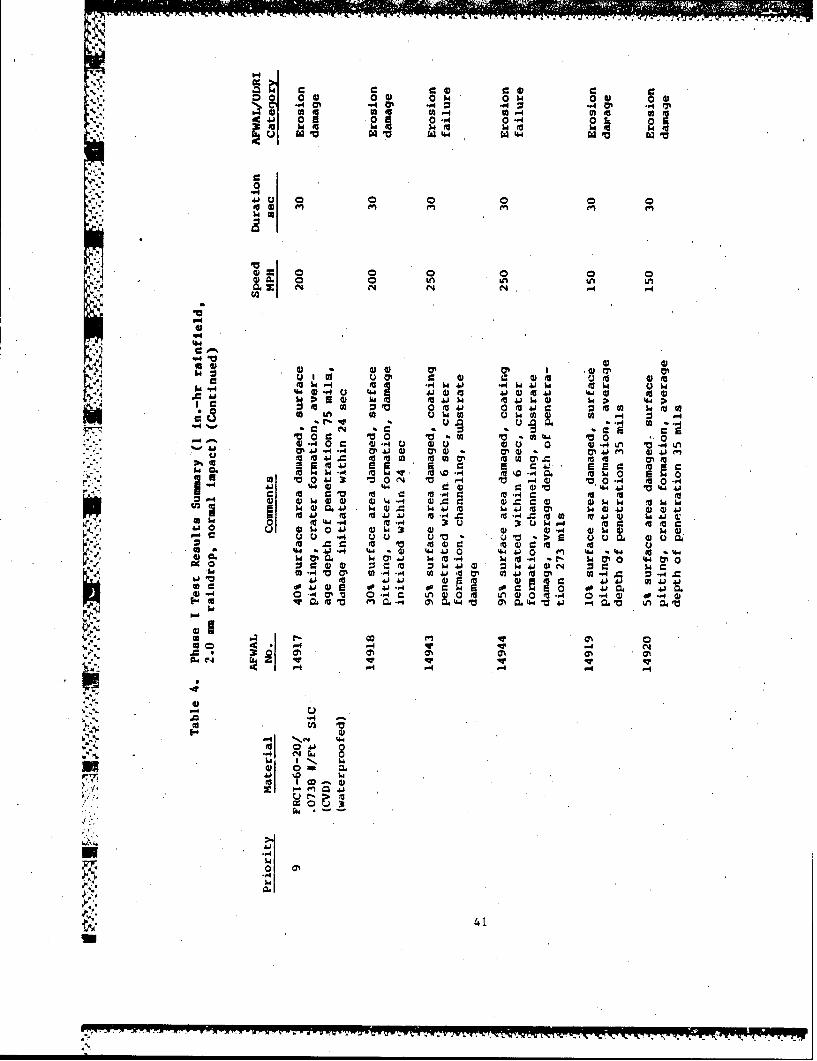
Table 4 is a summary of the normal impact test results for the rigid tile
class of mr-terials. The procedure followed during the test runs was to moni-
tor the visual condition of the test articles using a closed circuit TV system
employing stroboscopic stop motion techniques. The test samples were first
brought up to the desired speed on the whirling arm and then the rainfield was
turned on, starting the rainfield timing clock. For the bulk of the tests,
the test duration was 30 sec. The test run was considered complete when Lhe
rainfield was shut off. The time of occurrence of surface damage (made
evident by the sudden appearance of a white spot on the black tile coating, or
a perceptible blemish on the white surface of uncoated tile samples) was noted
to the nearest 0.05 minutes (3 sec) on the rainfield timing clock. The
surface damage time reported is believed to be accurate to * I sec, based on
past experience with the apparatus. Exceptions to the 30 sec runs were made
when extensive damage occurred early in the run, in which event the run was
terminated, or when no surface damage was apparent, and a 60 sec run was made.
31

o0 4 0-m.40 h.4
0 $
wl 0 0n
0
Cfl 49 49i
-4 4
5.4 C 4a
05 41 z C )
41 o 40 4m 40%
z 00. 0lIc tEl O'D 0 , "
0 UiS 041 41 hito4G 01 %'d~ c5 - 4 0 04
4 1 14. Ci %4' u $Aj V04 to 66 00 go Aj
ai ElO 1" aihiS 41-4 0 o m6 4 01 u 4 w 0 01 u0
6 0S~ -,Bo o05n 4J (4b0z '4 Q24PW 39 hi4h to 4IA 0 -4 0. %4 4 A %d 0
C 0. M S'l0 * S loCL£h 0e404 C%41 0 4 ON m
w16( ITS~ w'b~ v
3490h00i0 ~ i
hi hi 05NO h. 05- 49.4 -~566 -4" 50 -4 S'd. N4'432S

00 b40 i0 0 0U-A z -0 a OC0 0-4 toMO#
0-40046A en en
to~ a) mf'e
c66 (A
IN -
17 0u I
41 00 FA $ MNWt
0- 0 o4 s jw -. AWC . 0ato0 U 0 P44A 0 4gL4 A
U00UOOMai 0 w Oia 42 f
17 0' *1 10:0 Oi V~ to-*4
,q-' N 140 Iwo 0 0AM
w t ME to M -.4 'm w E A*4U 0000 a4 ) .C0 4 V0 c 0o C
$4 4) U u >U 00*E 4o ~ U
0) U O 04 U 30 00 to ;64
U4 2 0 4W0 - 04 0 U Za 4) I 4 Mw24
M* to J 000 'b*r44 m k A 4 0 m 0
a. 0 m-0 24 04u 00 00 -4 00 c0 OU (A4C0 M wI m %W.~ 4
044w 0 ; d I
-PC10Wr 0 U -. 1
P. %4
0i -a 03 a 4 %
0O 0*'
.4 14 -4
0 0CM41 N u
UU 3N *
33

00
0.0 00 U
4104 0 + 0+ 0+ 0+ 0 00
04 N N N N-
tr -40 61I 0'0 -4 1411 An-0~-.0 . 0 'S. v .- 1C a0' 0 1. j 21 0 F
Cu LI. .* - i 0 4I v ' Q0 6 A * into0 0 0 a~0 I P- ~ 0
ah;.0 O=4 J IV0'O 41O 00 Nh. 41 w'.~ fa
a V 4 U0 v -0 hi C1W0 41 N ' hi
A1 MO M 0 *.J 4 0 4h 041
en ~ 0 410
0.0 Og O 000410 0- V40* 0 04*, CL 0 411. 410 0av m 0a
h a A0 A Ali (a A0 0 0 "4 '4' 4W '41"'0hi 0 hi- '4. .0 "'0 - AiC - hC
SC 00W 0OL WOW h.00 0 Z0 0001 0jc10 0 00 Q0(00 0 u 4-A0. 414(
si 4o 00 000 0 4FA .fhi NW0 2LI 00$ 1 l 0 0 m O i to
Q1 0 ) ,0 u4' 0'10 W a aW410' u
0'0N
.. 4 .4 -4 P-
A C
-34

0 0 00 a h0 0 $ 004
0 w- 00 A-4 01
0 I
0 ea w
coC
41 t
.0 0) = .0r
*. I 0 mo 0 oto~ c 0 uw 0 1 8 .4 ch 5 4h U0t
.4 wo -4. 0.0 to*Ub. ~go ~ ~~~~~~ 41J40 4h~ 0 05 5 i
.0 000j 0 4) ~ 0.
tPFA4J 0%0 w WJ .
41o o--4.o 4
1wC6toto 4 i 4 VO 4 5V45 0 PC4b V50- 454 r o 45 ) to to
0 0O.4 il 0 0 '0 - 1&.i 0 4100hi41 41Wt~ 4. 41w hi ON V
-faA .4 -0- .vG 0 mk a 4 41 w --A
0 U0 Q
*. 0 1W
c 0 ~ 01.. o o 3
lw 000 l jk . wwAJ0 1>A 4 " 1A .
V ul . m33

0 04 0 0 0 0 IV0
0 0
0go
41 00 0 A 6m
00% 0' 0 00 0 0,V2 % 4 4 N 4 .4
0 u u 4 *hi hi h4) hi V
00 0 0 V 0 0
tocIE ,-4-.4 E -.4* '*0 t 41to0-4- -IE A 41 4
hiO Vi PC ri dO .h4 ai 140 hto 0 01- c 0C 1011 0
14.4) 41' 40' 4 11 14 4JA 41401414
. 41 A to1 0u 0 0 MU(at01 d 4 w 0M 4.
0 41 Q. 0 ~ C 0a~ 00u 0) 0 u1 01 01 -W M 1 0101
%4 U %400 00 004 31' %W30 a 341 1.4 w-4 1. 11
hi 0 0.4 0-4 0-4 c 2c4 IA w0 -. 3 t 0 0 w 0-.4u
a0 a 00 00OA 41 ~ 04 to 0 1 I4 14 0 0 0n 0 > 010 01 01 01 0110
to hi 1.0 4.6 0 1. 140 41 hO
14 M 4v ON-4 0 4'* 0 0)A10 0 01 01M 0.04 LM0 010
00 000 00 0-4 04h -4 0
"'0 1 1141 66 -4 .4* 0 1 1
1-0~~~f A'ar- N4 ,J'
hii
00I
U .4 i1 0 4.
00 ~ N N N NN N6

0 0) 0 0 0 4 05 O4i 0h sOhe0wON..~ ON 0%4 .0O - 2 .4 = 0= .
0fJ P~0 5 0 -4 0.4 M -40 so~
WOLaA
a. i
* 01
4J0 0) 0'0
104 0 0
c .C Q 0 -A I 0 0i %4 -4
-. -0 tr 41 ON 0.4 0 ON -41 -4 ( A t l4a
10t 3 V44 oA
a .4 c 00 -4r .4 . .51 so u -. 4o to* ) u"u6 -. 40 qt 4 o V -4 " 0 >~ -.J to3 &m .4J 4
05 5 Q 0. u 5 0 0Ca 0- 00 4~ -. c m -I -4
.0 toi C.' 0a 0 E . )Aj40 0 1tji I .0a 4 6 40c w2. .0 m o
u 0c "0 4) .to L 0 UT6 0 C
0% 0% %WV v nPC N-jaetoo.)0' 00 ~ u oaa o ~
a,~ P4 ~ 4 Na- Va- ujhl .a ~* Uh 0 5 50 J 5 ~ s a sao aos s a~ vcp*C .4a o -4 oa aP4a.o oaa 0 ~ 00 00
'a0 0I! l 0wa 0 w~.
C4 AN fn 4.ila ' 4.4.
00 ~ 90 4 0' .'37

M0 0 0 0 0@ 04)0$Qj o04) 0AIF0 A 4( -
P-4
14 04 IV0,-% 0 0) '4 00
"0 0 0 IA 0
'a0-44
C44 ~ 41 = 41 %0 M4)4 4) 41 IVO 6U
Stir 0w. 0j w0 c )4 0*Z 0 z 0to& 41 u a1 . u .4 4140)U(
V4%o $04 I 0 ~ ad0'444>.I0 w~ II MM u~. 000 10 00 1
000 cuE 0- " OW- 0 ) 4w04 tr 04 4) *r A.O0aLN(i N(iA
to.4 40104 4 td C
A00 ..4 .4 .0..-A0c 0 02.MO. *0 4 E4 2MM -40 C %44P
02 fa00 01 2 -401 P- A
2r 4 co0 -.4. MV (a~ 4 4) M )
0 4)0 0 A.0 01q 4 3 ) 4)44 W 41 0 41 M
1A j - 4 t 04 0 0 930 0 l4) -. 4 4 -4ON.
c2 4) A -40.e -A 2-.4 0 Q)414 214 0 aOP0 00. *j, d4 A.-.d p41 0 (A o u t 041
0 00 J 41..4 41 coL a2 01 0410 ~~~ ~ , 41- U" ..4 U 0 0 M 0 .4 0
(P 41 3 0%E- A E M O 0.0 U , 4 0 4 co
C-4 6,
I.-14.P1 .
En
to4 U Li oM 00. *-4c 0
4) 0W 0U38

.- ,-.-p~am J. - m -. ON -. 0- -
~0 ~04 O@0 0 r:
to1 01 01t
J a 0 w 0 0
u (a
w. w
w) -.
14O 0"0C
~010 4) A . $ ) 5 ) A'V A o414 04J ( i4Ld to3C
41' )6 L 4

7-7- , s a7 ys aw-w--, - - -T 7
00 01 4 04 01w 0 4
a-A- 2 -4 2 0FA 0-4 CO-4 0- 4 0E
.4 44 w W144 14 144
4P4 'a060
i-4 1 jj A o$4JU 0j 07 m 0 t 0 1 ) 4 -4Ii 93A A U M -W = cr C
5=000 04 0 0 u 0
A 514 0 0 0 A.50. N 44 1 &.e
A -41
Ai I.4 f -I 14 4r 4 a0a 4)C 4) 0 cu4) = 0) 4*"4
C $4 1 tr A.) 41 0 w C44 4 m -. 10(a id =41 04Ja
$4 oo 544 a0 $44 44 4 =9 .W O
4) M1 a 44 to i 4)4 001 W Q V I-4p 0 .a te0 0 E a a t 03. d.0 5.4.4 Go -14 (0 04 0 M0 0. 4) 4 0 n )(a* Q V (n4~ a 0 0.10- A 0-2U-4 .4 1.4.(0
8 ~ ~ ~ . P-4 3 5'. j 5s0 a
04 : o o4 00 m4m o
.4;4
-..0 24C
$ 4 1 1 1
41 -*0 to .41) N 014
14
o 3
40
4 0% O2q U4 P
-P4
50 1 01 0 w 0 j l0 04
43 0 0 0 0l 0
-4
-4m0r 4 - A n -4U
00 CL' .4 to w~ 0 Q *E 0.1 a 04 *4.4 4 -0 '05 "4 0 e '1 o~
40 E 00. 41 w 4 - a 4 w )4.
0-4 0a 0*j W A 30 4) 0) 4 04 0 443
Si I*4' .14' 4~.4 . 4) 4wA 0~ 0%-4 .0 (n %W 4
w% t; CP 41 ( -4 5w 0 4 0 %4 )
1- 4 -1 1 . 41 fa a -,
C.) go 4 J 4 ) 1A iAAA6 d 1- 0CG .aa0 d 10 1Q
610' )0 eo- DU -IV (a43 . aV A 4 n 21
:~IV Ni~'a%
-41.

41,
adi Ai AQhi0 A
0 ~ Ajs
"O 0 5 104 3 .. 4 a.
0o4 .
14A % w4)v >-
-'.1to 43 ~ 4
0i 10 >i -4 hi 0 U iO
a1~1 ai a #a 150o oP4 C
5010 4 415 0 i.%4 q64 A 0-
U 564.0 zw5dv 1515 wc0 ~ 0 t4, A
-6 I'i A
ON 0.4 0 .4.h
~3 I 4 (N ~P15
.00 ..
15 In S
N I642

A test series with the samples oriented at 45 deg to the rain impact direction
(Configuration 6, Figure 4) was also run using the RCG-coated FRCI-20-20
material. Results up to 250 mph for 60 sec 'time exposure indicate no damage.
Because of a limitation on the available number of test samples, an undersized
sample was also run at 300 mph. The sample was damaged, but since the damage
was initiated at the lower tapered edge of the sample, which was especially
exposed because of the small sample size, this result is highly suspect.
Pre- and post-exposure documentation of the surface condition, depth of
penetration, and damage definition of all of the test articles was carried out
under the supervision of Charles J. Hurley, University of Dayton Research
Institute Aerospace Vehicle Coatings Group, and the negatives are on file with
AFWAL/MLS. All of the test damage figures shown here are from that series of
photographs.
1. RCG-Coated TPS
On the basis of the test results cited in Table 4, the damage threshold
levels for the RCG-coated rigid tile materials have been evaluated and are
summarized in Table 5. A 30-sec exposure duration in a 1-in. per hour rain-
field is consistent with typical shuttle launch conditions if the launch were
to occur through moderate rain. As was expected, the FRCI-20-20 with standard
thickness RCG coating performed the best, surviving at 200 mph for 30 sec
exposure with only the onset of subsurface fractures evident after the test
(Figure 5). At 300 mph, the RCG coating was partially removed within 3 sec of
exposure (Figure 6).
The onset of damage to the LI-2200 samples with the standard RCG coating
thickness occurred around 150 mph after exposure for 60 set. with appearance
of an isolated star-shaped crack in one of the two exposed samples (Figure 7).
At 200 mph, the RCG coating was penetrated and removed within a 12 to 18 sec
exposure (Figure 8).
Damage to the FRCI-20-12 samples with standard RCG coating thickness was
initiated within 21 sec at 150 mph, in the form of the removal of a small
portion of the RCG coating (Figure 9) on one sample, and extensive subsurface
microfracturing was noted on both samples after the run. The onset of damage
43

Table 5. Damage Threshold Levels (1 in./hr rainfield,2.0 amraindrop, normal impact)
Damage ThresholdSpeed
Priority Material mph!duration,sec
RCG-Coated and Waterproofed
I FRCI-20-20 200/30Is LI-2200 150/ 60+8 FRCI-20-12 < 150/21lb FRCI-20-12, 2x std. coating 200/60+Ic LI-900 < 150/18
RCG-Coated, Unwaterproofed andFilled With Water
Id FRCI-20-20 200/30
Rare and Waterproofed
5a FRCI-20-20 < 150/66 LI-2200 < 150/37 FRCI-40-20 (< 150/9
Bare, Underwaterproofed and Filledwith Water
5& FRCI-20-20 < 150/6
SiC (CVD)-Coated and Waterproofedlbf2
6b LI-2200, 0.0234 l/tcoating < 150/37a FRCI-40-20, 2.5% coating 2 < 200/187b FRCI-40-20, 0.0456 lb/ft 2coating 150/309 FRCI-60'-20, 0.0738 lb/f 2 coating 150/30
10 AET-40-20, 0.049 lb/ft coating < 150/18
44
14940 200 miph 30 sec.
Fig. 5. Pre- and post exposure, FRCI-20-20 with standardRCG ceramic coating, shoving subsurface fracturesafter 30 sec exposure at 200 mph
45

7* M 1 1
4 10
14941 300 mph 3 sec.
Fig. 6. Pre- and post exposure, FRCI-20-20 with standardRCG ceramic coating, showing damage after 3 secexposure at 300 mph
46

14503 .150 otph 60 sec
Fig. 7. Pre- and post exposure, LI-2200 with standardRCG ceramic coating, showing star-shaped crackafter 60 sec exposure at 150 mph
47

14500 200 m~ph 30 'sec
Fig. 8. Pre- and post exposure, LI-2200 with standardRCG cera-mic coating, showing damage after30 sec exposure at 200 mph
48

15021 150 mph 2 e
Fig. 9. Pre- and post exposure, FRCI-20-12 with standardRCG ceramic coating, showing surface cracks and'loss of coating segment after 24 sec exposureat 150 mph
49

for a 30 sec duration would be expected at slightly below 150 mph. On the
other hand, the FRCI-20-12 samples with twice the standard RCG coating thick-
ness performed as well or slightly better than the FRCI-20-20 with standard
coating thickness. At 200 mph, isolated fractures were found after 60 sec
exposure time or longer in the case of FRCI-20-12 (Figure 10), whereas damage
occurred within 30 sec in the case of the FRCI-20-20 with standard coating
thickness.
For the LI-900 smples with the standard RCG coating thicknese, portions
of the coating were removed within 18 sec of exposure at 150 mph (Figure 11).
At 200 mph, the coating was penetrated within 6 sec and the LI-900 tile sub-
strate was eroded complecely away at the inboard end of the samples. The
damage threshold level for the LI-900 sample is estimated to be around 100 mph
or less for a 30 sec exposure.
To investigate the possibility of anomalous results due to the takeup of
water in the tile during the rain exposure run, one series of test samples
(FRCI-20-20 with standard RCG coating thickness) was left unwaterproofed and
each sample was filled by water immersion just prior to the test runs. Within
the overall range of test result variations, there was no discernible differ-
ence in performance between the waterproofed and the "unwaterproofed and
filled with water" test articles.
2. Uncoated Rigid Tile
All of the uncoated tile test articles were damaged by surface pitting
and cratering at 150 mph test speeds. In the case of the bare waterproofed
FRCI-20-20, the onset of surface pittipg occurred 6 sec into the test run
(Figure 12). Pitting was noted at around 9 sec into the 150 mph run of the
bare, unwaterproofed and filled with water FRCI-20-20 samples. However, the
accuracy withtin which these times can be determined is such that sample
performanee must be considered comparable between these two types of samples
for this material. The bare, waterproofed LI-2200 material was pitted within
3 sec of exposure at 150 mph and the extent of the pitting appeared somewhat
greater th,,n that for the FRCI-20-20, which was exposed slightly longer (6 to
12 sec versus 3 sec). Surface pitting of the bare, waterproofed FRCI-40-20
50

7WT- IrT .d Vr
14947 200 mph 60 sec
Fig. 10. Pre- and post exposure, FRCI-20-12 with twice standardthickness RCG ceramic coating, showing one subsurfacefracture after 60 sec exposure at 200 mph
51
IM 77 7 t 7-7 7 TW 7 -

Fig. 11. Pre- and post exposure, LI-000 with standard RCGceramic coating, showing ceramic coating lossand tile erosion after 18 sec exposure at 150 mph
52

17777
14524 150 mph, 6 sec
Fig. 12. Pre- and post exposure, FRCI-20-20, showingcratering after 6 sec exposure at 150 mph
53

test articles started at approximately the same time as noted for the
FRCI-20-20 (i.e., approximately 9 sec into the run) at 150 mph, with the
extent of the pitting also being comparable.
Thus, the damage threshold for all of the bare rigid tile mazerials
tested is below 150 mph and could be considerably below that for a 30 secIexposure. As a means of evaluating the relative performance of the three
uncoated materials tested (FRCI-20-20, LI-2200, and FRCI-40-20), the extent of
the surface erosions produced by a 30 sec exposure at 200 mph was compared.
Visual inspection of the test samples indicated that the depth of erosion of
the LI-2200 samples is perceptibly deeper than that for the FRCI-20-20 and
FRCI-40-20 samples. On a qualitative basis, it is difficult to establish a
significant difference between the FRCI-20-20 and the FRCI-40-20.
*- It is concluded that the rain erosion resistance of the FRCI-20-20 and
FRCI-40-20 class materials is generally superior to that of the LI-2200
material. However, the damage threshold levels for the three materials are
less than 150 mph, possibly by a considerable margin for a 30 sec exposure.
3. SiC (CVD)-Coated TPS
A relative comparison of the SiC-coated test articles is more difficult
than for the RCG coated test series because of the differences in coating
thickness as well as changes in substrate tile material. Thus, the
.0456 lb/ft 2 SiC coating on FRCI-4(e-20 (Figure 13) and the .1738 lb/ft 2 SiC
coating in FRCI-60-20 appear to have a damage threshold level of around
150 mph for 30 sec exposure, although both experienced onset of surface
pitting. Localized penetration and erosion of the LI-2200 tile with
.0234 lb/ft2 SiC coating occurred within 6 sec at 150 mph (Figure 14) and
limited coating penetration occurred within 24 see at 150 mph in the case of
the AETB-40-20 with a 0.049 lb/ft 2 SiC coating.
It is very difficult to compare the different SiC-coated materials
b ecause of the mismatches in coating thickness and/or exposure conditions
among the various test articles. It would appear thet even fairly thick
coatings experience the onset of pitting within 30 sec at 150 mph, but varia-
tions with coating thickness cannot be ascertained from the available data.
54
-------------------------- ' -.- *- - - - -- A . -& -

I
'AA
.1
14928 150 mph 30 sec
Fig. 13. Pre- and post exposure, FRCI-40-20 with 0.046 1b/f.2SiC (CVD) coating, showing crateririg after 30 secexposure at 150 mph
55

14916 150 mph 6 sec
Asii A.
Fig. 14. Pre- and past exposure, Li-2200 with 0.023 lb/f t 2 sic(CND) coating,'showing cratering and tile erosionafter 6 sec exposure at 150 mph
56

4. Material Response
The damage observed in the thin RCG-coated tile materials differs from
that seen in the uncoated and the SiC-coated configurations. Failure first
occurs In the RCG ceramic coatir.; in the form of subsurface microfractures at
the interface between the coating and the porous tile substrate (rigure 15).
In contrast, the SiC-coated materials and the bulk, uncoated tile materials
fail by pitting and cratering of the surface layer. In all cases, erosion of
the underlying porous tile material proceeds fairly rapidly after the surface
coating or layer has been penetrated.
Damage progression in the RCG coating is characterized by propagation of
the subsurface microfractures from the interface with the porous tile sub-
strate to the surface, followed by the formation of star-shaped surface cracks
and then the appearance of circumferential cracks around the star-shaped
radial cracks. Coating segments'are lost after the appearance of the radial
and circumferential cracks. The various steps in this sequence can be seen in
Figure 6, which shows an FRCI-20-20 sample after 3 sec exposure at 300 mph.
Very similar results and obserations have been noted by investigators at
Rockwell International and by Varner (Ref. 7), who used metallic impactors to
study tile damage.
The onset of damage to the CVD SiC coatings is characterized by the local
fracturing of small chunks of SiC-impregnated surface materials over a small,
roughly circular area apparently within a drop impact zone, which are ini-
tially driven into underlying voids. The fractured chunks remain within the
underlying crater at most of the damage sites in the FRCI-40-20 and FRCI-60-20
samples exposed at the lowest test speed (150 mph for 3C sec; see Figure 13).
The damage craters have sharp edges, suggesting a shear failure, in contrast
to the classical lipped crater typically formed when metals are impacted.
Sharp edged craters are also formed in the bare tile sample surfaces. The
similar crater formation seen in the uncoated and CVD coated samples is not
unexpected, since the CVD process represents an impregnation to some depth of
the porous tile surface rather than the building up of a ceramic layer on the
tile surface such as in the RCG ceramic coating case. When seen under mag-
57
U

113 200 mph 30 sec
W,77 7'qp f
K-, k--
i4'1
Fig. 1.Pre- and post exposure, LI-2200 with 0.023 lb/ft 2 sic(CVD) coating, shoving coating loss and tile erosionaf ter 30 sec at 200 mph
58

nification, the FRCI-40-20 SiC coated sample surfaces have a straw-like
appearance because the Nextel and Silica filaments ,making up the basic tile
can still be seen even though impregnated with the SiC.
At higher speeds and/or longer exposure, the fractured StC-impregnated
surface chunks are ejected from the subsurface craters and underlying tile
material is eroded to greater depths. There is no obvious indication that
damage from one site is propagated to adjacent sites except where drop impact
areas overlap, in contrast to the RCC ceramic response. Thus, damage progres-
sion in the uncoated and SiC-coated test articles mainly involves enlargement
and deepening of surface cratevs only (compare Figures 14 and 15). One of the
reasons for using CVD SiC coating was to strengthen the surface of the porous
tile material, in addition to providing desired optical surface properties.
The performance of the SiC-coated FRCI-40-20 suggests an improvement ov',. he
bare tile in rain impact resistance, and might warrant further exploratiL-.
However, there was virtually no difference in performance between the uncoated
and SiC-coated LI-2200 test articles.
C. DISCUSSION
The experimental evidence for the RCG coated tile samples indicates that
failure is caused by flexure of the glass coating. At the lowest damage-
inducing rain impact speeds, fractures visible through the glass coating are
initially formed at the ceramic coating/porous tile interface. This has
occurred in test articles exposed during the present test series in the AFWAL
Mach 1.2 Rain Erosion Facility, and in samples exposed to the AFWAL/Bell Mach
3 Rain Facility, where larger (3 x 3 in.) test articles are used, during
experiments carried out by Rockwell International experimenters on many of the
same TPS candidate materials. At higher impact speeds or longer exposure
durations, these subsurface microfractures propagate to the surface, even-
tually forming a radial (star) and circumferential crack system, followed by
the removal of poetions of the tile coating, thus exposing the underlying tile
material to further erosion damage.
A NASA-sponsored study of the damage resistance of TPS tiles under single
projectile impact, using an aluminum impactor and steel ball bearings (Ref. 7),
59

has produced similar results. Two types of damage were noted: (1) bending
failure identical to that described above for the ROG ceramic coating, and
(2) a Hertzian cone type impact failure (not obvious in the RCG ceramic
coating failures of the Phase I tests).
A review of the literature indicates that most analyses of liquid drop
impact of brittle (ceramic) materials (e.g., Ref. 8) consider the case of
thick bulk mterials, generally modeled as occupying a half-space. The
material damage threshold is assumed to be reached when preexisting surface
microcracks are enlarged and extended by a tensile surface wave (the Raleigh
wave,) propagating out from the point of impact. A characteristic circumferen-
tial crack pattern is thus formed around the impact, region, as has been shown
experimentally (see Figure 11, Ref. 9, for example). Some of the damage
produced in the RCG ceramic coating by ball bearing experiments discussed in
Ref. 7 (referred to as the impact failure case) seems similar to the circum-
ferential or, ring cracking modes shown in Ref. 9.
These considerations indicate that there may be at least two damage modes
involved in producing failure of the rigid TPS under rain impact conditions:
(I) bending of the ceramic coating resulting in tensile failure at the inter-
face with the porous tile substrate, and (2) cratering of the surface because
of shallow tensile surface waves interacting with preexisting surface micro-
cracks. In the case of the very thin ceramic RCG coating presently used on
the TPS, the flexural ,failure is apparently reached at lower raindrop impact
speeds than are needed to cause the surface cratering type damage in the
coating. However, if the thickness of the ceramic coating is increased, the
increased flexural stiffness of the coating could result in a shift of the
failure sites to the surface by the shallow tensile surface wave interaction
with existing surface microcracks.
After the initial subsurface fractures in the ceramic coating have
propagated to the surface, some of the bulk material cratering mechanisms,
particularly hydraulic penetration into the fracture network and jetting of
water drop outflow against elevated crack edges in irregular crater contours,
could also come into play. That is, once the coating damage threshold has
60

been exceeded, fracture propagation mechanisms co.mon to both thin and thick
(bulk) ceramic layers can be expected.
The pitting or crater-type failure of the bare and CVD SiC-coated test
specime-is may be related to the "impact failure" damage mode characterized in
Ref. 7, although the SiC surface fragments or chunks remaining in the impact
craters are generally not circular but irregular in shape. Differences in
projectile breakup (i.e., raindrop breakup in the present experiments versus
no breakup of the impacting steel ball bearings in the Ref. 7 experiments)
could also lead to differences in tile response.
A very interesting paper by C. Schmitt (Ref. 10) provides data for thin
skin composite structures which include a configuration analogous to the rigid
TPS under discussion. Of particular interest is a composite with an outer
skin of 10- to 30- ail thick E-glass/epoxy over rigidized, expanded, low
density polyurethane foam. Polyurethane or fluorocarbon protective coatings
were applied to the outer skin to improve rain impact resistance. The coro
density varied from 5 to 15 lb/ft 3 , i.e., roughly in the same range as for the
current TPS substrate materials, and the outer skin thicknesses were also
comparable to the R G ceramic coating thickness.
At or below a certain thickness of outer skin (20 mil or less) no amount
of protective coating or core (substrate) density change improved performance;
failure was almost instantaneous, 'with separation of the ov.ter skin from the
foam and possibly some crushing of the foam. Inter-ply, delamination of the
laminated outer skin also was common. With an increase in outer skin thick-
ness to 30 mils, however, there was a marked improvement in time-to-failure
with increase in expanded foam core density for exposure at 400 mph in a
1-in.per/hr'reinfield. Part of the improved performance may be attributable
to the high strain-to-failure ratio, which is characteristic of the E-glass
layer, as opposed to the brittle RCG coating on our tile specimens.
Thus, while it was concluded in Ref. 10 that the density of the core
(substrate) material was the most significant materials parameter in achieving
rain impact resistance, it was also necessary to have a sufficiently thick
outer skin before substantial improvement was achieved with increased
substrate density.
61
'7
- _31

The results of the present experiment appear to be consistent with the
trends suggested in Ref. 10. Increases in tile substrate density for the same
generic materials class seemed to increase rain impact resistance; an Increase
in ceramic coating thickness likewise resulted in improved impact performance.
The role of the tile substrate material is obviously of primary import-
ance in determining TPS rain impact performance. Key material properties
would appear to include density, porosity, compressive strength, and compres-
sive modulus. Some typical physical and mechanical properties of the tested
tile materials are given in Table 6. The tiles are listed in the order of
relative performance, beginning with the worst (LI-900) and proceeding to the
best (FRCI-20-20). The strongest correlation with improved performance
appears to be shown by the through-the-thickness (TTT) compressive modulus.
The density of LI-2200 is slightly higher than that for the FRCI-20-20, but
its performance is inferior to that of the FRCI-20-20. Similarly, FRCI-20-12
and LI-2200 have the same compressive strength, but the LI-2200 performance is
definitely superior to the FPCI-20-12.
Table 6. Typical Physical and Mechanical Properties
Property LI-900 FRCI-20-12 LI-2200 FRCI-20-20
Density, 0.14 0.19 0.35 0.32g/cM
Compresslore 28 132 130 250Strength, psi
Compressive 0.7 1.05 2.7 3.7Mo.ulus, (TTT)10 psi
Sond Speed, 0.59 0.58 0.73 0.8910 cm/sec
Acoustic 0.08 0.12 0.26 0.29Impedance10 g/cm sec
62

... . .... .... .......... .-. . ...-- . *- . ..... ' . w... . . . . r,- - - - . ' - 7 m
If the 3GC-coated TPS materials can be modeled as the classical beam or
plate on an elastic foundation, with the tile substrate providing the founda-
tion modulus for the thin ceramic "plate," then thu tile compressive modulus
becomes a key parameter in the reaction tetween the coating and the tile.
Rowever, the peak bending stress in the beam or plate is not very sensitive
to the modulus of the foundation (Ref. 11). .rom the analysis of a railroad
track rail, a 100% change in the foundation modulus only produces a 16.52
change in the maximum bending -stress in the rail (Ref. 11, p 28). On this
basis, the difference in compression moduli for the tile test materials would
not be expected to cause a wide variation in damage threshold levels.
As discussed in Appendix A, the pressure loadi.ag on the TPS surface
during a raindrop impact at 200 mph is on the order of 16 ksi, based on the
water hammer pressure (Ref. 9) and typical materials properties for water and
the RCC coating. For a 2.0 m drop diameter, the pressure duration is between
I and 2.5 usec. The acoustic impedance mismatch at the RCG ceramic coating/
tile substrate Interface is also large, so that very little stress is
transmitted into the substrate from the initial stress wave produced at the
surface by the raindrop impact. Flexure of the RCG coating is probably well
developed before the end of the pressure loading, however, because of the
short travel time (approximately 0.07 usec) for a stress wave to traverse the
thickness of the 0.38 mm,(15 mil) coating. A reduction in the acoustic
impedance mismatch between the RCQ coating and the tile substrate would allow
more of the impulsive-like loading to be taken up in the substrate and might
also reduce the subsequent flexural motion of the coating, thus reducing the
flexural stress in the coating and leading to improved rain impsct resistance.
63
-,~ r
!-

VI. CONCLUSIONS AND RECOMMENDATIONS
The Phase I testing was successful in bracketing damage threshold
levels for three of the RCG-coated test materials (LI-2200, FRCI-20-20, and
FRCI-20-12 having twice the standard 15 ail coating thickness). The damage
threshold level was found to be less than 150 mph for LI-900 and FRCI-20-12
vith standard coating thickness, and the bare tile materials (LI-2200, LI-900,
FlCI-20-12, FRCI-20-20, and FRCI-40-20). The CVD SiC-coated test articles
(LI-2200, FRCI-40-20, FRCI-60-20, and AETB-40-20) failed at or below 150 mph
under 30 sec'exposure durations. Difficulties with the testing technique
precluded valid test data on the flexible cloth layers because of complica-
tions arising from',cloth- layer mounting constraints and coupling between
sample distortion and centrifugal force loads on the test samples. Alterna-
tives to the present approach are needed to provide valid test data on the
flexible blanket class of matmrials.
Damage to the RCG-coated tiles is initiated by flexural bending stresses
in the ceramic coating; similar behavior vas reported for tests using larger
test samples on the Mach 3 AFWAL/Bell facility and also for drop tests using
an aluminum cylinder with a hemispherical head as an impactor.
The relative ranking of the rijid TPS materials with a standard thickness
RCG ceramic coating in regard to rain impact resistance is:
FRCI-20-20 (best)
LI-2200
FRCI- 20-12
LI-900 (worst)
The compressive modulus of the material appears to correlate most
strongly with the rain impact resistance of the RCG-coated tile specimens.
Although there is a considerable spread in the compressive modulus properties
between the several materials, there is no dramatic improvement in damage
threshold speeds from the weakest (LI-900) to the strongest (FRCI-20-20)
material, i.e., from somewhat under 150 to 200 mph. This could perhaps. have
63
F R 7

been anticipated from the analogy with the railroad track rail on an elastic
foundation, cited above.
The performancs of the bare tile material does not appeer to be substan-
tially improved by infiltration, impregnation and sintering using CVD SiC on
the tile surface. While there was some improvement in rain impact resistance
of the F=-40-20 material, there as no change in the case of the LI-2200.
Finally, the rain impact resistance of the FRCI-20-12 was substantially
improved by doubling the thickness of the RCG ceramic coating. This result
could be expected because of the increased flexural stiffness of the ceramic
coating and the role of the flexural failure modes in determining damage
threshold.
Future studies are recommended to examine the role of impact angle of
incidence in determining damage threshold levels under more realistic or
operational rain encounter conditions (as opposed to the 90 deg, normal impact
angle studied here).
It is also recommended that improved rain resistance be studied by use of
tile substrate surface hardening techniques such as CVD SiC infiltration or
the shuttle tile densification technique combined with application of the
standard RC ceramic coating. The limits to which impact resistance is
improved by increasing the RCZ ceramic coating thickness should also be
est&blished. Trade-off studies between improved rain impact performance and
weight penalty will require such data.
To establish a better understanding of the relative importance of various
materials properties, another series of experiments is recommended with the
same basic tile materials, but two and three times the -tandard RCG ceramic
coating thickness, to see if more dramatic improvements in, rain impact resis-
tance are achievable with increase in compressive modulus or tile density, as
was the case in Ref. 11. The test matrix should provide for a tighter varia-
tion in test duration at a given test veloc!ty than was possible in Phase I,
in calling out specific velocities and durations to determine damage initia-
tion, damage propagation, and rate of damage onset.
66
4 4b~R"
77-!W 47777!

REFERENCES
1. Wahl, N. E. Rain Erosion Characterization of Thermal Protection SystemMaterials at Subsonic Velocities, AFML-TR-72-145. Air Force MaterialsLaboratory, Wright-Patterson Air Force Base Ohio, Aug. 1972.
2. Stein, M. and R. C. Ketterer, Reuseable Surface Insulation FlightEnvironvent Test Program. N&SA/KSC Engineering and Rockwell Inter-national Launch Operations, Florida. Interim Report, 18 July 1975, FinalReport, Dec. 1976.
3. Teller, V., D. Cade, and P. DeWolfe, "Ice Impact Testing of Orbiter TPSMaterials Progress Report,' Operational Design Projects, RockwellInternational, December 1982 (Briefing).
4. Hurley, C. J. and G. F. Schmitt, Jr., Development and Calibration of aMach 1.2 Rain Erosion Test Apparatus, AFML-TR-70-240, Air Force MaterialsLaboratory, Wright-Patterson AFB, Ohio 45433, Oct. 1970.
5. Schmitt, G. F., Jr., Liquid and Solid Particle Impact Erosion, AFML-TR-79-4122, Air Force Materials Laboratory, Wright-Patterson Air Force Base,Ohio 45433, Nov. 1979.
6. Hackworth, J. V., "A Mechanistic Investigation of the Rain Erosion ofInfrared Transmitting Materials at Velocities to Mach 2", Proc. 5thInt. Conf. on Erosion by Solid and Liquid Impact, pp 10-1 to 10-12,Cambridge, England, Royal Aircraft Establishment, Farnborough, England,3-6 September 1979.
7. Varner, j. R. and K. Ono, Damage Resistance of Space Shuttle OrbiterThermal Protection Tiles, Final Report, Interchange No. NCA2-OR390-901,1979, NASA Ames Research Center, Moffett Field, California. 1979.
8. Evans, A. C., Y. M. Ito, and M. Rosenblatt, "Impact Damage Thresholds inBrittle Materials Impacted by Water Drops," Proc. 5th Int. Conf. onErosion by Solid and Liquid Impact, 3-1 to 3-10, 1979.
9. Adler, W. F., "Rain Erosion Mechanisms for Optical Materials," Optics inAdverse Environments, Vol. 21, SPIE Pr.'c. (1977).
10. Schmitt, C. F., Jr., "The Subsonic Rain Erosion Response of Composite andHoneycomb Structures," SAMPE Journal, September/October, pp. 6-13, 1979.
11. Hetenyi, M., Beams on Elastic Foundation, The University of MichiganPress, Ann Arbor, Michigan, 1958.
67
P POW'

APPENDIX A. THEORETICAL CONSIDERATIONS
The magnitude and spatial distribution of the pressure exerted on a solid
surface by a liquid drop impact is a complex function of time, requiring
hydrodynamic calculations using numerical techniques for accurate determina-
tion (Refs. 8 and 9). For the purpose of this discussion, the magniiude of
the pressure can be estimated from the water hammer pressure equation:
PLCL (1)
(PL4/Pccc)
where p is density, c is sound speed, V is the raindrop impact speed (normal
to the surface), and the subscripts L and c refer to liquid and surface coat-
ing, respectively. The product Pc is called the acoustic impedance,
Z =pc (2)
Equation (1) is rewritten in terms of the acoustic impedance
P + (zL/Z V (3)
An upper limit for the duration of the impact pressure loading is given by
tL2d (4)L = L
which is the time required for a compressional stress wave to reach the rear
surface of a raindrop of diameter d and reflect back to the impact surface as
a tensile, 'unloading wave. The sequence of events involved in a raindrop-
collision with a plane' surface is more complicated than is indicated' by such a
simple wave passage model. Of particular importance is lateral outflow of the
liquid as the raindrop area of contact with the surface increases (Ref. 9).
69
-~~~1 77't<

The transit time of a stress wave through the thickness direction of a
TPS coating is
t h ()c c
Ic
where h is the coating thickness and cc is the sound speed in the coating
material.
For analysis, the following materials properties have been assumed for
estimating raindrop impact of an RCG-coated FRCI-20-12 tile specimen:
Table A-1. Assumed Acoustic Impedance Properties
/
P c zDenpity, Sound Speed Impedance
Material g/cmy 105 cm/sec 105g/cm2 sec
Water 1.0 (PL) 1.46 (cc) 1.46 (ZL)
RCG Coating 1.69 (P ) 4.0 (ce) 6.83 (Zc)
RSI Nownal 0.19 (ps) 0.58 (cs) 0.12 (Zs)(12#Ifr )
Meas.* 0.215 0.456 0.098
*Sound speed measurements provided by J. Linn, The Aerospace Corporation.
From Eq. (3) 'and the properties assumed in Table A-i, the water hammer
pressure has been calculated as a function of raindrop impact speed and is
plotted in Figure A-i. The pressure is in the range from 0.8 to 1.6 kbar for
impact speeds in the range of the present experiments, i.e., from 150 to
300 mph. Since typical static compressive strengths of borosilicate glasses
are on the order of 8.4 kbar (Ref. A-i), the Phase I test speeds do not appear
.70
71, , ,

I 2.5
2.0RCRGCOATING
0~1.0
0.3 WATER Ham R 1. REXSSURm E c
QU RTZn
Z I71+

|Ito be high enough to produce gross crushing or pulverizing damage to the RCG
coating surface from compressional loading. The surface damage to bulk
silicate-based glasses reported in Ref. 9 was initiated by impact pressures on
the order of 3 kbars, at speeds of around 500 mph. In Ref. 8, the onset of
surface damage is attributed to the propagation of pre-existing surface cracks
caused by the tensile pulse associated with the Rayleigh surface wave that
emanates from the impact site on a bulk specimen.
On the basis of estimated magnitudes of the raindrop impact pressure
loadings, it seems reasonable to conclude that the dominant failure mechanism
Li the RCG-coated TPS specimens was coating flexure and not surface cratering
in the coating. From Eq. (4), an upper limit on the pulse duration for a 2.0
diameter raindrop is
tL - 2.5 Vsec
From Ref. 9, it is estimated that for such a case, the impact event is com-
pleted in approximately I usec. From Eq. (5), the transit time for a stress
wave to propagate through a standard thickness RCG coating (0.38 mm) is
t = 0.07 usec
Thus, since the pressure pulse duration is in the range from 1 to 2.5 Usec, it
is long compared to the transit time through the coating, and flexural motion
of the coating is probably well developed before the end of the pressure
loading from a single raindrop impact.
During very early times after a raindrop impact, before the flexural
response of the coating has been excited, the magnitude of the initial stress
wave transmitted into the tile substrare, a, can be estimated from the rela-
tion (Ref. A-2)
Z -Zs s c (6)o Z 4Z
c s c
72

where a is the magnitude of the stress induced in the coating, assumed here
to be water hammer pressure developed upon raindrop impact of the coating.
Taking the values for the acoustic impedance from Table A-I, Eq. (6) yields
Is- 0.028oc
Thus, because of the large impedance mismatch (Zc Z.) between the RCG
coating, and the FRCI-20-12 substrate, the interface between the coating and
the tile almost appears to be a free surface to the initial stress wave in the
RCG coating and very low stress amplitudes are transmitted into the substrate.
Equation (6) is based upon the assumption that the coating and substrate
materials are continuous, homogeneous, elastic materials. Consequently, the
application of the relation to porous tile materials is only approximate, but
still provides some insight into likely responsive behavior early in the
impact event.
In the same fashion, an approximate estimate of the pressure loading
imposed upon a bare tile specimen by raindrop impact can be made using Eq.
(3), which likewise is valid only for continuous, homogeneous materials.
Consequently, the results can only be regarded as order of magnitude values.
Using Z. in place of Zc in Eq. (3) yields
p - 0.41 x 10- 3 V(in mph), kbar
For an impact speed of 150 mph, p - 0.062 kbar. Since the static compressive
strength of FRCI-20-12 is on the order of 0,0)8 kbar, surface crushing would
be expected, as was observed during the Phase I tests.
73
MMM -MM

REFERENCES
A-I. Moray, G. U., The Properties of Glass 2nd Edition, Reinhold PublishingCorporation, New York, New York, 1960.
A-2. Kinslow, Rt., Stress Waves in Composite Laminates AEDC-TR-65-69, 1965,ARO, Inc., Arnold Air Force Station, Tennessee.
74
*U.S. GOVERNMeNT PRINTINGO9FICE 1985-47-M9