railway technical web pagesno.!2! ! railway!passenger!vehiclecapacity! railway!technical!web!pages!...
TRANSCRIPT
Railway Technical Web Pages Infopaper No. 2
Railway Passenger Vehicle Capacity An overview of the way railway vehicle capacity has evolved.
by
Piers Connor1
Introduction The capacity of a railway vehicle is a crucial part of the railway system. For passenger vehicles, it is always a compromise between what is acceptable to the passenger in terms of accessibility and comfort and what is acceptable to the operator in terms of efficiency and cost. The results are not necessarily ideal for either. This paper examines some of the issues.
The range of vehicle capacity depends largely on the use of the vehicle or its expected journey distance. In this respect, for a short average journey as experienced on urban routes and metros, capacity will be at the top end of the range, most passengers being expected to stand while, for longer journeys, capacity will be reduced by the need for more comfort, more seating, more amenities and the consequent reduction in standing space.
The other aspect of capacity is determined by the design of the loading and unloading system – where passenger doors are located, their size, their design and their operating system. A wide variety of systems are available and they will have an effect on dwell time management and vehicle capacity.
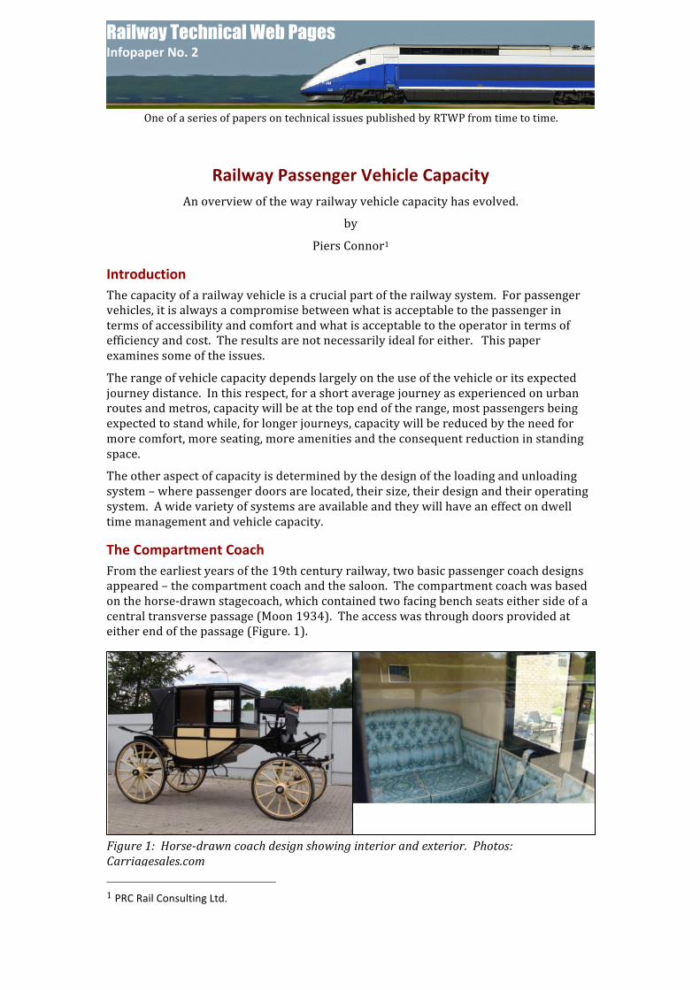
The Compartment Coach From the earliest years of the 19th century railway, two basic passenger coach designs appeared – the compartment coach and the saloon. The compartment coach was based on the horse-‐drawn stagecoach, which contained two facing bench seats either side of a central transverse passage (Moon 1934). The access was through doors provided at either end of the passage (Figure. 1).
1 PRC Rail Consulting Ltd.
Figure 1: Horse-‐drawn coach design showing interior and exterior. Photos: Carriagesales.com
One of a series of papers on technical issues published by RTWP from time to time.

Infopaper No. 2 Railway Passenger Vehicle Capacity
Railway Technical Web Pages 13th August 2011
The design was soon multiplied for railway coaches where the number of compartments expanded with the length of the vehicle, which was stretched as far as the infrastructure constraints would allow so that, by the beginning of the 20th century, 60ft (18m), 10 compartment, 4-‐axle vehicles were in use on commuter routes (Jenkinson 1996). With 5 persons being seated on each bench, such a vehicle could accommodate 100 passengers plus standees (Fig. 2). Later versions managed to squeeze in 6-‐seater benches. The quality of the seating was variable but quantity was the main criterion for the lower classes of travel. Even in a compartment with a length of 6ft (1.8m), it was possible to get 5 persons standing between the knees of 10 seated passengers. “First class” seating was provided in some vehicles, allowing fewer, wider seats and and a longer compartment length. One typical example, recorded by Jenkinson (1996), showed that the reduction in capacity in a First Class vehicle amounted to 50% compared with an equivalent 3rd Class Coach.
The big advantages for the compartment coach were in its capacity for large numbers of seated passengers and its ability to unload them quickly. With one doorway for 10-‐18 passengers (depending on the standing load), it was possible to unload a whole commuter train arriving at a London terminus in 30 seconds. Many experienced commuters would open their door and alight from the train while it was still moving and some were agile enough to be able to arrive at the end of the platform before the front of the train.
Loading was not much slower but it suffered from the disadvantage that it relied upon passengers closing the doors themselves. Regular commuters did, from education and habit, but there were always some doors left open and it required a number of platform staff to ensure all were closed before dispatching the train. This was expensive in staff and sometimes caused extended dwell times.
The Saloon Coach The other popular passenger coach design was the saloon. This type originated in the US, where the standard 19th century vehicle had end access through (usually) open platforms leading onto the seating area via a central walkway.
A typical example is shown in Figure 3, with a car built in 1907 for an “interurban” line, basically a commuter route common around the major cities in the eastern and mid-‐US. Original examples of this type had open end entrance platforms but later examples were enclosed, as shown here. The end platform also allowed access between vehicles, something not introduced in the UK until 1892. This type of vehicle had to have a stronger body shell than the compartment type, simply because of the lack of internal structure. Its advantage over the compartment vehicle was the improved interior circulation but the loading/unloading was slower. Later versions of the saloon coach were adopted for long distance routes in Europe and elsewhere and various designs included mixed layouts combining compartments and a side corridor. In the UK, a
Figure. 2: Typical suburban, 10 compartment coach, with seating for 100 persons, built 1922. Photo: Bluebell Railway
Infopaper No. 2 Railway Passenger Vehicle Capacity
Railway Technical Web Pages 13th August 2011
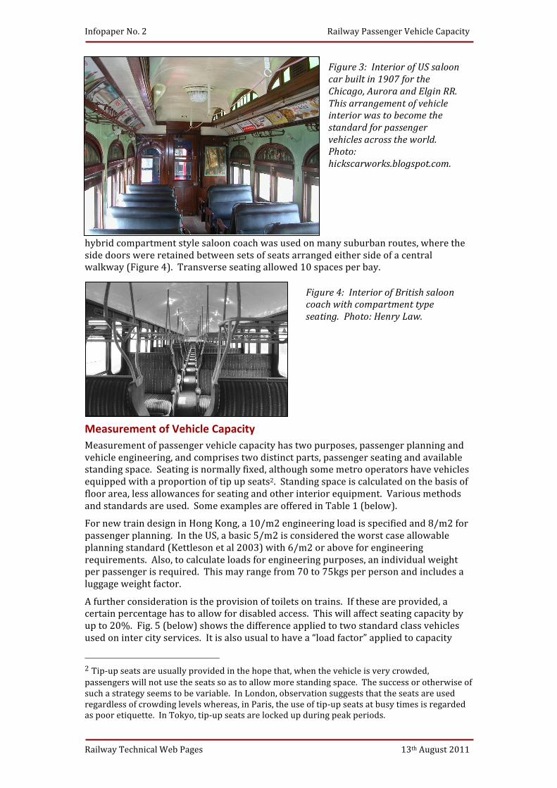
hybrid compartment style saloon coach was used on many suburban routes, where the side doors were retained between sets of seats arranged either side of a central walkway (Figure 4). Transverse seating allowed 10 spaces per bay.
Measurement of Vehicle Capacity Measurement of passenger vehicle capacity has two purposes, passenger planning and vehicle engineering, and comprises two distinct parts, passenger seating and available standing space. Seating is normally fixed, although some metro operators have vehicles equipped with a proportion of tip up seats2. Standing space is calculated on the basis of floor area, less allowances for seating and other interior equipment. Various methods and standards are used. Some examples are offered in Table 1 (below).
For new train design in Hong Kong, a 10/m2 engineering load is specified and 8/m2 for passenger planning. In the US, a basic 5/m2 is considered the worst case allowable planning standard (Kettleson et al 2003) with 6/m2 or above for engineering requirements. Also, to calculate loads for engineering purposes, an individual weight per passenger is required. This may range from 70 to 75kgs per person and includes a luggage weight factor.
A further consideration is the provision of toilets on trains. If these are provided, a certain percentage has to allow for disabled access. This will affect seating capacity by up to 20%. Fig. 5 (below) shows the difference applied to two standard class vehicles used on inter city services. It is also usual to have a “load factor” applied to capacity
2 Tip-‐up seats are usually provided in the hope that, when the vehicle is very crowded, passengers will not use the seats so as to allow more standing space. The success or otherwise of such a strategy seems to be variable. In London, observation suggests that the seats are used regardless of crowding levels whereas, in Paris, the use of tip-‐up seats at busy times is regarded as poor etiquette. In Tokyo, tip-‐up seats are locked up during peak periods.
Figure 4: Interior of British saloon coach with compartment type seating. Photo: Henry Law.
Figure 3: Interior of US saloon car built in 1907 for the Chicago, Aurora and Elgin RR. This arrangement of vehicle interior was to become the standard for passenger vehicles across the world. Photo: hickscarworks.blogspot.com.

Infopaper No. 2 Railway Passenger Vehicle Capacity
Railway Technical Web Pages 13th August 2011
calculations. This is to allow for uneven loading on individual trains and for the “peak within the peak” often experienced on urban and inner suburban routes. These factors range from 70% to 86%.
Table 1: Seating & Standing Capacity of Selected Suburban Rolling Stock
Passengers in excess of capacity (PIXC) In Britain, a target for restricting overcrowding on rail vehicles is set as “Passengers in excess of capacity” (PIXC). This was defined by the government as greater than 10% of the vehicle’s seating capacity or of an allowance of 0.55m2 per passenger depending on the type of vehicle. Some variations were subsequently introduced for London suburban routes and the 110% figure increased to 130% in 2008. Government literature (House of Commons 2003) suggests that there is much confusion over definitions.
The London Overground routes operator defined overcrowding as, “more than 1.6 passengers per square metre” (TfL 2009) or 38% over the total number of seats. This data was issued when Class 313 trains were in use and there was an average of 77
Date Stock Seats/metre length
Standees/metre length
Passengers/ metre length
1922 SE&CR Compartment Coach 5.55 2.78 8.33
1945 Southern Compartment EMU (4-‐SUB)
6 2.5 8.5
1947 Southern mixed Comp./Saloon EMU (4-‐SUB)
4.96 2.81 7.77
1972 Southern outer suburban EMU (4-‐VEP)
2.72 2.81 5.53
1994 Class 365 EMU 3.29 2.5 5.79
2002 Class 444 EMU 3.41 2.5 5.91
2010 Class 378 EMU 1.7 7.05 8.75
2009 LU 2009 Tube Stock 2.16 8.97 11.13
2010 LU Surface S Stock 2.27 9.12 11.39
Fig. 5: Seating plans for two standard class vehicles used on the Pendolino train sets. Diagram: Virgin Trains
Infopaper No. 2 Railway Passenger Vehicle Capacity
Railway Technical Web Pages 13th August 2011
seats/vehicle. The replacement Class 378 vehicles have an average of 35 seats/vehicle, less than half the replaced stock. In engineering terms, the question is simply to find the floor loading requirements of the vehicle structure and the consequent energy and braking requirements under the heaviest loading conditions. London Underground, for example, adopts a variable load, setting a standard of 8 passengers/m2 between doorways and 6/m2 elsewhere. For passenger planning purposes, 7/m2 is adopted as the “crush” load condition.
Door & Seating Configuration The layout of doors and seats provides a significant impact on vehicle capacity. Doors need to be designed for optimum dwell time requirements while sufficient seating is essential to provide reasonable comfort for a majority of longer distance passengers. Some operators provide a guide to the maximum length of journey time passengers should be expected to stand. In the US (Kettleson et al 2003) and the UK, this time is typically 20 minutes.
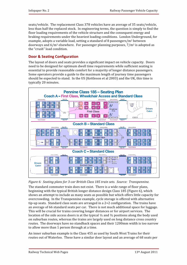
Figure 6: Seating plans for 3-‐car British Class 185 train sets. Source: Transpennine. The standard commuter train does not exist. There is a wide range of floor plans, beginning with the typical British longer distance design Class 185 (Figure 6), which shows an attempt to include as many seats as possible but which offers little capacity for overcrowding. In the Transpennine example, cycle storage is offered with alternative tip-‐up seats. Standard class seats are arranged in a 2+2 configuration. The trains have an average of 66 standard seats per car. There is not much additional space for luggage. This will be crucial for trains covering longer distances or for airport services. The location of the side access doors is at the typical ⅓ and ⅔ positions along the body used on suburban routes, whereas the trains are largely used on long distance cross country routes. The doorways have no standback spaces and their 1200mm width is too narrow to allow more than 1 person through at a time.
An inner suburban example is the Class 455 as used by South West Trains for their routes out of Waterloo. These have a similar door layout and an average of 68 seats per
Infopaper No. 2 Railway Passenger Vehicle Capacity
Railway Technical Web Pages 13th August 2011
car in their recently rebuilt state. In their original state, there was an average of 79 seats per car. The reduction in seating has allowed an increase of standing space.
At the other end of the scale, many heavy metro car designers adopt a minimalist approach to seating. In Hong Kong, the MTRC originally specified a 24m car with 5 sets of 1400mm double doors per side and wide connecting gangways (Ball & Vint, 1981). The cars had all longitudinal seating for about 50 persons. Each car was designed for a full load of 375 persons. This principle has been maintained for all subsequent builds. The design capacity was originally based on 7/m2 for standing passengers. This was later increased to 8/m2. Similar levels of occupancy are used in other Asian cities.
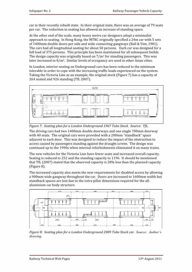
In London, interior seating on Underground cars has been reduced to the minimum tolerable in order to cope with the increasing traffic loads experienced on the system. Taking the Victoria Line as an example, the original stock (Figure 7) has a capacity of 264 seated and 926 standing (TfL 2007).
Figure 7: Seating plan for a London Underground 1967 Tube Stock. Source: TfL. The driving cars had two 1400mm double doorways and one single 700mm doorway with 40 seats. The original cars were provided with a 200mm “standback” space adjacent to each door. This was designed to reduce the impact of the obstruction to access caused by passengers standing against the draught screen. The design was continued up to the 1990s when internal refurbishments eliminated it on many trains.
The new vehicles for the Victoria Line have fewer seats and increased overall capacity. Seating is reduced to 252 and the standing capacity to 1196. It should be mentioned that TfL (2007) stated that the observed capacity is 28% less than the planned capacity (Figure 8).
The increased capacity also meets the new requirements for disabled access by allowing a 900mm wide gangway throughout the car. Doors are increased to 1600mm width but standback spaces are lost due to the extra pillar dimensions required for the all-‐aluminium car body structure.
Figure 8: Seating plan for a London Underground 2009 Tube Stock car. Source: Author’s drawing.
Infopaper No. 2 Railway Passenger Vehicle Capacity
Railway Technical Web Pages 13th August 2011
A feature of many new vehicles intended for the heavy urban routes around London is for seating near doorways to be removed and for tip-‐up or “perch seats” to be provided.
Conclusions Railway vehicle capacity requirements vary widely according to the length of route and density of occupation. Generally, standing spaces are measured as passengers per square metre. These range from 4/m2, considered tolerable in the US and Western Europe to 8/m2 in Asian cities. These variations can be said to be due to both physical and cultural differences. Load factors should be applied to account for variations in train loading.
Longer, commuter and outer suburban routes tend to limit standing to 20 minutes for any journey and any more than 10% above seating capacity was regarded as overcrowded. The UK Department for Transport raised that limit to 30% in 2008.
Designs for vehicles should taken account of the loading and unloading requirements and allow space for standback at doorways. Some regard for the storage of luggage may be required for longer distance or airport services.
Care should be taken in deciding the capacity requirements for rail vehicles. An ideal layout designed for a particular route will largely restrict the use of this vehicle for its whole life, particularly if large width or multiple doorways are chosen. A more versatile vehicle may end up as a compromise, not ideally suited to any route. A forward looking and system orientated approach is essential to obtain the best result.
Infopaper No. 2 Railway Passenger Vehicle Capacity
Railway Technical Web Pages 13th August 2011
Appendix 1 (Kittleson et al 2003) Many railway engineering projects express rolling stock loading requirements as follows:
AW0, empty weight,
AW1, weight with seated passenger load,
AW2, weight with average peak-‐hour passenger load,
AW3, crush loaded weight.
Some variations include AW4 as an engineering load above AW3.
For US standards, passengers are usually assumed to weigh an average of 155 lb (70 kg).
Peak-‐hour passenger load is normally based on 0.4 p/ft2 (4 passengers/m2) of floor space in North America, 0.4-‐0.5 p/ft2 (4-‐5 p/m2) in Europe and 0.5-‐0.6 p/ft2 (5-‐6 p/m2) in Asia, after discounting space used for cabs, stairwells and seated passengers at 0.2/ft2 (2/m2).
Crush loads are 0.6, 0.6-‐0.7, and 0.8 p/ft2 (6, 6-‐7 and 8 p/m2) respectively. Caution: some systems and manufacturers use different designations, some systems report loading in excess of 0.8 p/ft2 (8 p/m2).

Infopaper No. 2 Railway Passenger Vehicle Capacity
Railway Technical Web Pages 13th August 2011
References Bolton, G., Turner, S. (2009), S Stock -‐ A new train for London’s Sub-‐Surface Railway, Presentation.
Harris, M [1966]. Great Western Coaches from 1890, David & Charles, Newton Abbot.
Hobbs, G (2009), Attachment to Letter to Transport Committee, London Assembly, 12 January 2009.
House of Commons Select Committee on Transport (2003), Seventh Report, 25-‐38, London.
Kittleson & Associates Inc. for Transit Cooperative Research Program (2003), Transit Capacity & Quality of Service Manual, TCRP, Washington DC.
Moon, A.N (1934), One Hundred Years of Railway Carriages, Journal of the Institute of Locomotive Engineers, London.
Passenger Focus (2007), The Pennine Class 185 experience; What do passengers think? Passenger Focus, Warrington, UK.
Ball, N D; Vint, J (1981), The Electric Multiple Unit Trains of the Hong Kong Mass Transit Railway, Proc. I. Mech E. Railway Division, London.
Neil, G (2007), Rolling Stock Information Sheets, Transport for London, London.
Websites:
http://en.wikipedia.org/wiki/British_Rail_Class_458 (Visited 28 Nov 2010)
http://en.wikipedia.org/wiki/E231_series (Visited 28 Nov 2010)
http://www.emus.co.uk/sub.htm (Visited 27 Nov 2010)