railway occurrence report - taic
TRANSCRIPT

TRANSPORT ACCIDENT INVESTIGATION COMMISSION NEW ZEALAND
R A I L W A Y O C C U R R E N C E R E P O R T
05-108 diesel multiple unit passenger Train 3334, fire, Auckland 23 February 2005

The Transport Accident Investigation Commission is an independent Crown entity established to determine the circumstances and causes of accidents and incidents with a view to avoiding similar occurrences in the future. Accordingly it is inappropriate that reports should be used to assign fault or blame or determine liability, since neither the investigation nor the reporting process has been undertaken for that purpose. The Commission may make recommendations to improve transport safety. The cost of implementing any recommendation must always be balanced against its benefits. Such analysis is a matter for the regulator and the industry. These reports may be reprinted in whole or in part without charge, providing acknowledgement is made to the Transport Accident Investigation Commission.

Report 05-108
diesel multiple unit passenger Train 3334
fire
Auckland
23 February 2005
Abstract
On Wednesday 23 February 2005, at about 0855, Train 3334, a Papakura to Britomart diesel multiple unit passenger train, suffered a traction engine fire while it was stopped at Signal 125, Auckland. The passengers were safely evacuated while the locomotive engineer multiple unit extinguished the fire using dry-powder fire extinguishers that were carried on board the train. There were no injuries. The safety issues identified were:
• the cleanliness of the engine surround
• monitoring engine compression and crankcase pressures
• a fire detection and suppression system.
Three safety recommendations were made to the General Manager Infrastructure and Rail at Auckland Regional Transport Authority to address these issues.


Report 05-108, Page i
Contents Abbreviations ............................................................................................................................................... ii Data Summary............................................................................................................................................. iii 1 Factual Information........................................................................................................................1
1.1 Narrative ...........................................................................................................................1 1.2 Site information ................................................................................................................3 1.3 Personnel ..........................................................................................................................4
The locomotive engineer multiple unit .............................................................................4 The train manager .............................................................................................................4
1.4 Locomotive event recorder ...............................................................................................5 1.5 Diesel multiple units .........................................................................................................5 1.6 Operating instructions for ADK class units ......................................................................6 1.7 DMU inspection and maintenance....................................................................................7 1.8 Detailed inspection of the fire-damaged engine ...............................................................8
Before engine disassembly ...............................................................................................8 Engine disassembly ........................................................................................................12
1.9 National standards ..........................................................................................................16 1.10 Tests and research...........................................................................................................16 1.11 Code of Federal Regulations, USA, requirements..........................................................17 1.12 Previous occurrence investigated by the Commission ...................................................17
Rail occurrence report 04-116, passenger express Train 1605, fire in the generator car, Carterton, 28 June 2004 .....................................................................17
1.13 Similar occurrences involving the DMU fleet but not investigated by the Commission ..............................................................................................................17
2 Analysis .......................................................................................................................................18 General............................................................................................................................18 Lubricating oil and engine coolant .................................................................................19 Failure of internal components .......................................................................................20 The cause of the fire .......................................................................................................20
3 Findings .......................................................................................................................................21 4 Additional Information ................................................................................................................22 5 Safety Recommendations.............................................................................................................23

Report 05-108, Page ii
Figures Figure 1 Route for Train 3334 (not to scale) ............................................................................1 Figure 2 Consist of Train 3334 departing from Papakura (not to scale) ..................................2 Figure 3 Train 3334 at Signal 125 (not to scale) ......................................................................3 Figure 4 Oil on ballasted track .................................................................................................4 Figure 5 Engine before disassembly.........................................................................................9 Figure 6 Build-up of dirt, oil and grease on top of the engine transmission housing...............9 Figure 7 Topside of engine after cleaning ..............................................................................10 Figure 8 Underside of engine after cleaning ..........................................................................10 Figure 9 Filler cap opening and dipstick ................................................................................11 Figure 10 Breather cap opening and displaced centre rocker cover gasket..............................11 Figure 11 Dust layer on the lining of the air intake to turbocharger ........................................12 Figure 12 Burnt electrical cables and fuel hoses ......................................................................12 Figure 13 Failure of centre rocker cover gasket .......................................................................13 Figure 14 Witness marks of lower gasket on centre rocker cover............................................13 Figure 15 Failed second ring of No. 6 piston ...........................................................................14 Figure 16 Electrolysis on liner of No. 4 cylinder .....................................................................14 Figure 17 Failed seals on No. 6 liner........................................................................................15 Figure 18 Scoring on No. 6 piston skirt ...................................................................................15
Abbreviations
ATRA Auckland Regional Transport Authority
ºC Connex
degrees Celsius Connex Auckland Limited
DA DMU
diesel alternator diesel multiple unit
FMP Fleet Maintenance Protocol
LEMU locomotive engineer multiple unit
m mm
metre(s) millimetre(s)
Toll Rail Toll NZ consolidated Limited
UTC co-ordinated universal time
Westrail Western Australian Government Railways

Report 05-108, Page iii
Data Summary Train type and number: diesel multiple unit passenger Train 3334
Year of manufacture: 1968
Date and time: 23 February 2005 at about 08551
Location: Auckland
Persons on board: crew: 5 passengers: about 380
Injuries: nil Damage: fire damage to engine components and wiring
Operator: Connex Auckland Limited (Connex)
Investigator-in-charge: P G Miskell
1 Times are New Zealand Daylight Time (UTC + 13 hours) and are expressed in the 24-hour mode.


Report 05-108, Page 1
1 Factual Information
1.1 Narrative
1.1.1 On Wednesday, 23 February 2005, Train 3334 was the scheduled 0748 Connex2 passenger service from Papakura to Britomart via Glen Innes (see Figure 1).
Figure 1 Route for Train 3334 (not to scale)
1.1.2 Train 3334 consisted originally of powered car ADK683 with non-powered car ADB778
coupled. However, because preceding Train 3030, the scheduled 0735 Papakura to Britomart via Newmarket passenger service, was cancelled due to a mechanical failure, the locomotive engineer multiple unit (LEMU) and the train manager of Train 3334 decided to attach a spare diesel multiple unit (DMU) set, ADK685 and ADB775, to the original consist to accommodate the extra passengers. Train 3334 departed Papakura with 2 powered and 2 non-powered cars marshalled as shown in Figure 2. There was no internal access between the DMU sets.
2 Connex was the operator of Auckland suburban passenger rail services.
N
Westfield
Panmure
Tamaki
Glen Innes
Meadowbank
Britomart
Manurewa
Newmarket
Papakura Train 3334
Otahuhu
Orakei

Report 05-108, Page 2
Figure 2 Consist of Train 3334 departing from Papakura (not to scale)
1.1.3 Train 3334 was crewed by a LEMU, a train manager and 3 passenger operators and departed
Papakura at 0810, 22 minutes behind schedule.
1.1.4 As the train approached Manurewa, the LEMU saw a light flashing on his control panel, indicating a low water level for No. 1 engine on ADK685. While stopped at Manurewa, he went back along the platform and checked the condition of the engine. He noticed a small amount of steam coming from the coolant tank overflow pipe, but was not unduly concerned and returned to his driving position.
1.1.5 The LEMU drove at reduced speed to Otahuhu, the nearest station that had a facility to top up the coolant tank on ADK685. After about 20 litres of water were added to fill the coolant tank, the warning light ceased flashing.
1.1.6 Train 3334 continued to Britomart, but as it approached Panmure the warning light began to flash again. Because of a scheduled stop at Panmure, the LEMU took the opportunity to go back and check ADK685 again. He saw that steam was again escaping from the overflow pipe, so on return to the DMU cab he radioed staff at Britomart and informed them that ADK685 had an overheating problem and should be withdrawn from service on arrival.
1.1.7 As the train travelled between Meadowbank and Orakei, the LEMU noticed that the warning light for the No. 2 engine on ADK685 also began to flash.
1.1.8 Approaching Britomart, Train 3334 was required to stop at Signal 125, which was displaying a stop indication. While waiting for a proceed indication on the signal, the LEMU was alerted by one of the passenger operators knocking on the left-hand exterior cab door and saying that there was a fire under the train. At about the same time, the LEMU received a “3-bell”3 coded message in his driving compartment. He looked back along the train and saw smoke and flames coming from under ADK685.
1.1.9 The LEMU instructed the train manager to get the signal panel operator at Britomart to call the Fire Service then he grabbed the fire extinguisher from behind his seat and went back to the fire. The LEMU was confronted with thick smoke and some flames coming from between the top of No. 1 engine and the underside of the passenger saloon. The fire was quickly suppressed after expending one extinguisher and partially expending a second extinguisher handed to him from the driving compartment of ADK685.
3 A “3-bell” coded message was an instruction to the LEMU to stop the train immediately.
ADK683 ADB778 ADK685 ADB775 to Britomart
crew access
no crew access LEMU cab
powered car
non-powered car

Report 05-108, Page 3
The train crew evacuated passengers from ADK685 via the driver’s compartment to an assembly point at the top of an embankment on the left-hand side of the track. Passengers travelling in ADB775, the rear car, vacated without assistance from the crew. Passengers in the leading DMU set remained on board the train.
1.1.10 Once the LEMU had extinguished the fire, he uncoupled the rear DMU set, applied the handbrakes and shut down the engines. The LEMU drove the leading set with its passengers to Britomart. The evacuated passengers boarded services travelling to Britomart via Newmarket.
1.1.11 On arrival, the Fire Service confirmed that the fire had been extinguished.
1.1.12 There were no injuries as a result of the incident.
1.2 Site information
1.2.1 Signal 125 was the Up directing signal located at 684.863 kilometres (km) on the North Island Main Trunk, about 288 metres (m) before the entrance to the tunnel leading to Britomart (see Figure 3).
1.2.2 The signal was within station limits and controlled from Britomart signal panel.
Figure 3
Train 3334 at Signal 125 (not to scale)
1.2.3 While the train was stationary at Signal 125, the breather cap from the No. 1 engine on ADK685 was projected about 1.5 m and was found between the Up Main and Down Main lines. Oil was observed on the ballasted track directly below the engine rocker covers (see Figure 4). ADK685 was towed to Toll Rail’s maintenance depot at Westfield where an examination of the fire-damaged components was conducted.
Signal 125
tunnel entrance
Train 3334
from Newmarket
to Britomart

Report 05-108, Page 4
Figure 4 Oil on ballasted track
1.3 Personnel
The locomotive engineer multiple unit 1.3.1 Tranz Metro4 recruited the LEMU in 2003 and he underwent induction and theory training at
Toll NZ Consolidated Limited’s (Toll Rail) Auckland training facility. His training included the suppression of oil and electrical fires with the same type of fire extinguishers carried on DMUs.
1.3.2 The LEMU had considerable fire fighting experience as a volunteer fire fighter for the New Zealand Fire Service and as a flight attendant with the national carrier.
1.3.3 After a period of supervised on-the-job training he was appointed to a full-time position in July 2004. At the time of the incident, his DMU certification was current.
1.3.4 He said that when he reached the fire on ADK685 there was a moderate breeze fanning smoke and flame towards the left-hand side of the train, the same side from which he discharged the dry-powder extinguishers. Holding his breath, he discharged the first extinguisher at what he thought was the seat of the fire on top of the No. 1 engine. As the dry powder suppressed the flame and smoke, he moved the nozzle about to deal with the remaining fire source. He thought that the first fire extinguisher was discharged in about 30 seconds, by which time the fire was left smouldering. He discharged about half of another extinguisher to ensure the fire was extinguished.
The train manager 1.3.5 The train manager had held certification for about 30 months after accumulating 2 years’ prior
experience as a passenger operator. All her experience had been on the Auckland suburban rail network.
1.3.6 The train manager travelled in the second car, ADB778, from Papakura to Glen Innes. At Glen Innes, she walked across the island platform and looked along the train to confirm that all remote doors had closed before re-entering the local door. She said that she did not see any steam or smoke coming from under the train.
4 Tranz Metro was the group within Toll Rail that had responsibility for the operation of Auckland suburban rail services. Connex became the operator of the suburban rail network on 23 August 2004.
breather cap missing
oil residue
Train 3334

Report 05-108, Page 5
1.3.7 After re-boarding the train, the train manager closed the remote doors and gave the 2 bells “right away” signal to the LEMU. After the train departed, she walked through to the front car and suggested to the LEMU that as the train was already full they go direct to Britomart.
1.3.8 While Train 3334 was stopped at Signal 125, the train manager became puzzled when she heard the “3-bell” alert in the driver’s compartment, so she walked to his door to find out what had happened. At that time, one of the passenger operators was outside the LEMU’s side window shouting, “Stop, stop, fire!”
1.3.9 Both the LEMU and train manager reached for the fire extinguisher. The LEMU took the extinguisher and went to put out the fire. After the Auckland signal panel operator responded to her emergency radio call, she went to evacuate passengers from the third passenger car.
1.3.10 By the time the train manager reached ADK685, the passenger operator had already started the evacuation process through the driving compartment door, and the passengers in the rear car were evacuating themselves.
1.4 Locomotive event recorder
1.4.1 The DMU was not equipped with a locomotive event recorder.
1.5 Diesel multiple units
1.5.1 The ADK and ADB passenger cars were originally owned by Western Australian Government Railways (Westrail) and operated in Perth. The motor unit, ADK685, was built at Commonwealth Engineering, New South Wales and the trailer coach ADB778 was built at Westrail’s own workshop facility, both in 1968. Tranz Rail5 purchased them from Westrail and commissioned them on the Auckland rail network during 1993.
1.5.2 The DMU consisted of an ADK powered unit permanently coupled to an ADB car to make a 2-car set. Multiple 2-car sets could be coupled to make 4-, 6- or 8-car trains.
1.5.3 Each ADK car was powered by 2 Cummins 6-cylinder diesel traction engines, each developing 138 kilowatts at 2000 revolutions per minute. The No. 1 engine provided traction power to the leading bogie and an alternator for battery charging on the ADK, while the No. 2 engine provided traction power to the trailing bogie and drove the Westinghouse brake compressor. The powered car was also equipped with a Lister diesel alternator (DA) that provided 23 kilowatts of auxiliary power, for saloon heating and radiator cooling fan operation.
1.5.4 The 2 traction engines on the ADK unit had separate cooling systems, but shared a single coolant tank mounted above the cabin adjacent to the radiator fans. The coolant tank was divided into 2 compartments, with each compartment supplying coolant to its dedicated traction engine. There was a filler pipe on both sides of ADK685. The coolant tank was normally filled from one side only, with the near side of the tank filling first before overflowing to fill the far side. Water flowing from both overflow pipes indicated that both sides of the coolant tank were filled.
1.5.5 The engine coolant was gravity fed to the water pump of each traction engine that delivered the coolant to the engine cooling system. The water in the engine block was controlled to a temperature of 82 degrees Celsius (º C) by means of a 3-way thermostatic valve and bypass loop.
1.5.6 The engine cylinders were enclosed within steel sleeves, called cylinder liners, which were cooled by circulating engine coolant. The coolant was retained in a space between the piston liner and the cylinder block by large rubber rings that formed a seal between the hot cylinder liner and the cooler engine block. Failure of this seal would result in engine coolant leaking into the oil sump below.
5 Tranz Rail was the rail operating company purchased by Toll Rail in May 2004.

Report 05-108, Page 6
1.6 Operating instructions for ADK class units
1.6.1 The LEMU’s operating instructions for ADK and ADB DMU’s were contained within Rail Operating Code, Code Supplement 4.16 that stated in part:
12.1 Engine Fault Lights
The indicator lights on the Locomotive engineer’s desk show that the condition of up to eight engine-transmission sets. The indicators are arranged so that the left hand row represents the leading engine transmission sets on the motor cars, the cars being taken in order from the front of the train, and the right hand row represents trailing engine transmission sets on the motor cars, the cars being taken in order from the front of the train. When engine and transmission are running normally, the respective indicator light should be on, except when a gear selection has just been attempted, when the light should go off for the duration of the gear changing period (up to 30 seconds). Fault conditions indicated by each light are: Engine oil pressure failure Overheat in engine or transmission Gear selection failure Low Water Low transmission oil pressure.
12.6.1 Traction Engine Shutdown The traction engines will shut down fully under the following conditions:
• Loss of oil pressure
• Loss of engine coolant
12.6.2 Traction Engine Idle Conditions
The traction engines will return to idle and the transmissions disengage under the following conditions:
• Overheating of engines
• Emergency brake application
• Broken or leaking brake pipe
• Vigilance device penalty
• Low transmission oil pressure
• The traction engine transmission light flashes evenly on then off to indicate low water level. If the engine shuts down, the water is very low. Water must be topped up before the engine can be started. If No.2 engine has shut down, the DMU is disabled. If No.1 engine has shut down, isolate the engine and proceed.
1.6.2 Each compartment of the coolant header tank had a 2-level switch. A green light flashed on the LEMU’s console when the coolant level of any compartment fell below the first level, known as “Low Level”. When the coolant level fell below the second level known as “Low, Low Level”, the engine shut down.

Report 05-108, Page 7
1.7 DMU inspection and maintenance
1.7.1 Tranz Rail purchased the DMU fleet from Westrail in 1993, at which time it received the respective drawings and maintenance schedules. However, there was no engine history documentation available at that time.
1.7.2 Toll Rail’s Mechanical Code M2000 determined that ADK cars were to be inspected at the following intervals:
• daily check every night
• A-Check every 6 weeks
• B-Check every 3 months
• C-Check every 6 months
• D-Check every 12 months.
1.7.3 The daily checks were carried out by qualified maintenance staff at the Westfield maintenance depot during the DMUs’ overnight downtime, and included checking defects reported by LEMUs.
1.7.4 The diesel engines were the subject of the following maintenance checks.
A-Check: Steam clean engines and surrounds. Change oil and filters. Check for fuel, water, oil, and exhaust leaks, and repair. Check engine wiring looms for damaged and loose wires.
B-Check Sample and change oil. Change fuel air filters. Check condition of fuel, water and oil hoses. Check operation of low water and oil pressure switches.
C-Check Same as for B-Check.
D¹-Check Change air cleaners. Check valve clearances. Clean crankcase breathers. Change all roof-mounted radiator hoses. Check and set injectors.
D²-Check As for D¹-Check but this time change out injectors.
1.7.5 Measurement of the diesel engine compression and crankcase pressures was not a requirement for any of the scheduled maintenance checks.
1.7.6 Each diesel engine was subjected to the following maintenance cycles:
Cycle 1 A-Check – B-Check – A-Check* ─ C-Check – A-Check – B-Check – A-Check ─ D¹-Check (* the fire occurred after this A-Check in Cycle 1)
followed by
Cycle 2 same as above except substitute D² for D¹.
After Cycle 2 was completed, Cycle 1 resumed, which meant that the full maintenance cycle on the traction motors was completed about every 2 years.

Report 05-108, Page 8
1.7.7 Maintenance records provided by Toll Rail confirmed that the most recent checks before the fire were completed on:
A-Check 13 January 2005
B-Check 29 November 2004
A-Check 14 October 2004
D²-Check 30 August 2004.
1.7.8 At the time of the fire, operational defects noted by LEMUs were logged in 2 different systems: the Connex Fleet Maintenance Protocol6 (FMP) database and the Loco 54D7 repair book that was used by Toll Rail.
1.7.9 The Connex FMP database for ADK685 had 4 entries between 1 February and 5 February 2005 (the day of the fire), all of which related to a flashing light on the LEMU’s console indicating low cooling water in one or both coolant tank compartments.
1.7.10 The Loco 54D book for ADK685 had 6 entries between 4 December 2004 and the day of the fire, relating to a flashing light on the LEMU’s console indicating a low level of coolant water. Only one of the Loco 54D book entries matched the Connex FMP database. Although the Loco 54D book recorded corrective actions such as pressure testing coolant systems, the recurring low water problem remained.
1.8 Detailed inspection of the fire-damaged engine
Before engine disassembly 1.8.1 The No. 1 engine on ADK685 was date stamped 19 February 1968. Toll Rail was unable to
provide records of the number of overhauls, if any, to which the engine had been subjected or the number of hours the engine had operated since any previous overhauls.
1.8.2 When the No. 1 engine was removed from under ADK685, the following was noted:
• the breather and oil filler caps were missing
• the oil dipstick was in place
• a section of rocker cover gasket both above and below the breather cap on the centre rocker cover was missing
• dry powder residue from the fire extinguisher was concentrated on the top of the engine (see Figure 5)
• there was a heavy build-up of dirt, oil and grease on top of the engine
• there was excessive dust accumulation in the turbocharger inlet
• there were burnt fuel hoses and electrical cables.
6 A system for recording defects and managing the transfer of vehicles to the care of a fleet maintainer. The responsibility for closing out defects lay with the fleet maintainer [Toll Rail]. 7 A record of defects identified by the LEMU, and repairs or adjustments carried out by the fleet maintainer. The book remained in the DMU cab and was checked by the maintainer during the daily check.

Report 05-108, Page 9
Figure 5 Engine before disassembly
1.8.3 The damaged engine was sent to an independent engine refurbishment company where
disassembly was carried out under the supervision of the Commission.
1.8.4 To determine the extent of the build-up of grease and oil and to facilitate a careful inspection of the outer casing of the engine, the dry powder, dirt, oil and grease were scraped off rather than cleaned with a water blaster. The build-up of dirt and grease around the exhaust manifold and near the engine transmission coupling was up to 25 millimetres (mm) thick in places (see Figure 6).
Figure 6 Build-up of dirt, oil and grease on top of the engine transmission housing
top of engine exhaust manifold
centre rocker cover
breather cap opening
intake manifold
exhaust outlet
turbocharger
air inlet
dry powder residue build-up of dirt, grease and oil
engine transmission

Report 05-108, Page 10
1.8.5 After the engine was cleaned, the paintwork was examined and it was found that on the underside of the engine the paintwork was intact, while on the topside the paintwork had suffered some discolouration, consistent with being subjected to excessive heat. The paint discolouration appeared to emanate from the exhaust manifold area of cylinders 3 and 4. Figures 7 and 8 show the paint condition on the top and undersides of the engine.
Figure 7 Topside of engine after cleaning
Figure 8 Underside of engine after cleaning
1.8.6 Figure 9 shows the oil filler cap opening. The dipstick had been in place but was removed
before the sump was drained. About 5 litres of water were discharged from the sump together with the oil. The water had not emulsified with the sump oil.
1.8.7 A representative of the engine manufacturer advised that the dipstick would normally dislodge before the breather cap when blow-by8 was excessive because the breather cap was usually adequately vented and screwed on.
8 Engine blow-by occurred when combustion gases escaped past the piston rings and entered the crankcase chamber.
No. 6 cylinder
paint discolouration near cylinders 3 and 4
general paint discolouration

Report 05-108, Page 11
Figure 9 Filler cap opening and dipstick
1.8.8 Figure 10 shows the breather cap opening and the damaged rocker cover gaskets above the
breather cap opening. The un-insulated exhaust manifold was close to the breather cap and damaged rocker cover gasket. Oil had leaked from the bottom rocker cover gasket and accumulated on the air intake manifold.
Figure 10 Breather cap opening and displaced centre rocker cover gasket
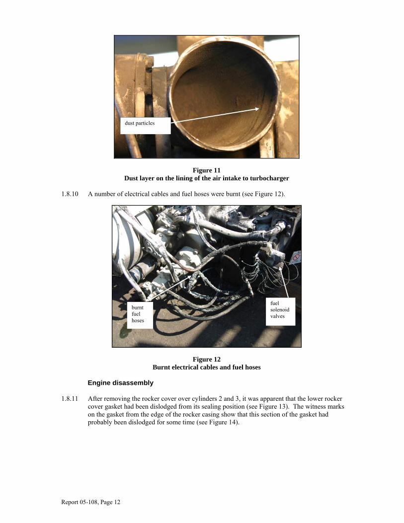
1.8.9 The air inlet to the turbocharger, downstream of the air cleaner, was lined with dust, indicating
the extent to which dust had entered the engine (see Figure 11).
filler cap missing
dipstick [removed]
breather cap missing
exhaust manifold damaged centre rocker cover gasket
build-up of oil due to lower rocker cover gasket having dislodged
Report 05-108, Page 12
Figure 11 Dust layer on the lining of the air intake to turbocharger
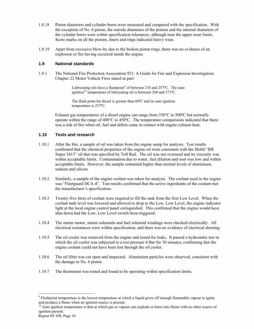
1.8.10 A number of electrical cables and fuel hoses were burnt (see Figure 12).
Figure 12 Burnt electrical cables and fuel hoses
Engine disassembly
1.8.11 After removing the rocker cover over cylinders 2 and 3, it was apparent that the lower rocker
cover gasket had been dislodged from its sealing position (see Figure 13). The witness marks on the gasket from the edge of the rocker casing show that this section of the gasket had probably been dislodged for some time (see Figure 14).
dust particles
fuel solenoid valves
burnt fuel hoses

Report 05-108, Page 13
Figure 13 Failure of centre rocker cover gasket
Figure 14 Witness marks of lower gasket on centre rocker cover
1.8.12 The tappet clearances and fuel timing were checked and found to be within operational limits.
failure of top rocker cover gasket
lower rocker cover gasket dislodged

Report 05-108, Page 14
1.8.13 When the cylinder head and cylinder liners were removed, the following observations were made:
• the middle piston rings on No. 1 and No. 6 pistons had failed
• the seals on liners 1, 3, 4 and 6 had failed
• liners 1, 3, 4 and 6 had heavy pitting. This is referred to in the industry as electrolysis, with liner 4 being the most severely pitted
• the side of No. 6 piston above the top ring was severely scored and deposits of aluminium melt were on the underside of the cylinder head.
1.8.14 All piston rings, liners and piston skirts had evidence of heavy wear. In particular the middle
rings of No. 1 piston and No. 6 piston had failed. Figure 15 shows the failed second ring on No. 6 piston.
Figure 15 Failed second ring of No. 6 piston
1.8.15 The liner of No. 4 piston had pitting marks with a diameter of about 2 mm (see Figure 16). The
pitting marks or electrolysis resulted from the implosion of steam.
Figure 16 Electrolysis on liner of No. 4 cylinder
failure of second ring
electrolysis pitting

Report 05-108, Page 15
1.8.16 The seals of liners 1, 3, 4 and 6 had failed to similar extents (see Figure 17).
Figure 17 Failed seals on No. 6 liner
1.8.17 No. 6 piston and its skirt had evidence of aluminium melt that was caused by excessive friction
developed between the cylinder and the piston. Some of the melt was deposited on the underside of the cylinder head (see Figure 18).
Figure 18 Scoring on No. 6 piston skirt
water seal
oil seal
melted aluminium above top ring
failed second ring
scoring of lower skirt
Report 05-108, Page 16
1.8.18 Piston diameters and cylinder bores were measured and compared with the specification. With the exception of No. 6 piston, the outside diameters of the pistons and the internal diameters of the cylinder bores were within specification tolerances, although near the upper wear limits. Score marks on all the pistons, liners and rings indicated heavy wear.
1.8.19 Apart from excessive blow-by due to the broken piston rings, there was no evidence of an explosion or fire having occurred inside the engine.
1.9 National standards
1.9.1 The National Fire Protection Association 921: A Guide for Fire and Explosion Investigation Chapter 22 Motor Vehicle Fires stated in part:
Lubricating oils have a flashpoint9 of between 210 and 257ºC. The auto ignition10 temperature of lubricating oil is between 260 and 371ºC. The flash point for diesel is greater than 60ºC and its auto ignition temperature is 257ºC.
Exhaust gas temperatures of a diesel engine can range from 350°C to 500ºC but normally operate within the range of 400°C to 450ºC. The temperature comparisons indicated that there was a risk of fire when oil, fuel and debris came in contact with engine exhaust heat.
1.10 Tests and research
1.10.1 After the fire, a sample of oil was taken from the engine sump for analysis. Test results confirmed that the chemical properties of the engine oil were consistent with the Mobil “RR Super 2413” oil that was specified by Toll Rail. The oil was not overused and its viscosity was within acceptable limits. Contamination due to water, fuel dilution and soot was low and within acceptable limits. However, the sample contained higher than normal levels of aluminium, sodium and silicon.
1.10.2 Similarly, a sample of the engine coolant was taken for analysis. The coolant used in the engine was “Fleetguard DCA-4”. Test results confirmed that the active ingredients of the coolant met the manufacturer’s specification.
1.10.3 Twenty-five litres of coolant were required to fill the tank from the first Low Level. When the coolant tank level was lowered and allowed to drop to the Low, Low Level, the engine indicator light at the local engine control panel extinguished. This confirmed that the engine would have shut down had the Low, Low Level switch been triggered.
1.10.4 The starter motor, starter solenoids and fuel solenoid windings were checked electrically. All electrical resistances were within specification, and there was no evidence of electrical shorting.
1.10.5 The oil cooler was removed from the engine and tested for leaks. It passed a hydrostatic test in which the oil cooler was subjected to a test pressure 4 Bar for 30 minutes, confirming that the engine coolant could not have been lost through the oil cooler.
1.10.6 The oil filter was cut open and inspected. Aluminium particles were observed, consistent with the damage to No. 6 piston.
1.10.7 The thermostat was tested and found to be operating within specification limits.
9 Flashpoint temperature is the lowest temperature at which a liquid gives off enough flammable vapour to ignite and produce a flame when an ignition source is present. 10 Auto ignition temperature is that at which gas or vapour can explode or burst into flame with no other source of ignition present.

Report 05-108, Page 17
1.11 Code of Federal Regulations, USA, requirements
1.11.1 A search for comparable standards relating to engine cleanliness was undertaken.
1.11.2 The USA Code of Federal Regulations Title 49, Volume 1, Chapter II Federal Railroad Administration, Department of Transportation Part 229 Railroad Locomotive Safety Standards stated in part:
Section 229.45 General Condition All systems and components on a locomotive shall be free of conditions that endanger the safety of the crew, locomotive or train. These conditions include: insecure attachment of components, including third rail shoes or beams, traction motors and motor gear cases, and fuel tanks; fuel, oil, water, steam, and other leaks and accumulations of oil on electrical equipment that create a personal injury hazard; improper functioning of components…. Section 229.91 Motors and generators A motor or generator may not have any of the following conditions:
a) Be shorted or grounded b) Throw solder excessively c) Show evidence of coming apart d) Have an overheated support bearing e) Have an excessive accumulation of oil
Section 229.101 Engines
a) The temperature and pressure alarms, control and related switches of
internal combustion engines shall function properly. b) Whenever an engine has been shut-down due to mechanical or other
problems, a distinctive warning notice giving reason for the shut-down shall be conspicuously attached near the engine starting control until repairs have been made.
1.12 Previous occurrence investigated by the Commission
Rail occurrence report 04-116, passenger express Train 1605, fire in the generator car, Carterton, 28 June 2004
1.12.1 On Monday 28 June 2004, the power generator unit at the rear of passenger express Train 1605
caught fire as the train berthed at Carterton. The fire probably resulted from the ignition of accumulated heated debris within the generator enclosure.
1.12.2 Among the safety issues identified was the need to ensure that there was no build-up of diesel, oil or dust particles around the diesel engine.
1.13 Similar occurrences involving the DMU fleet but not investigated by the Commission
1.13.1 In 2003, the Land Transport Safety Authority commissioned a report into several fire incidents that had occurred on the Auckland suburban DMU fleet. There were 6 incidents of fire reported between 1995 and 2002 and a further 6 similar occurrences between May and August 2003. Debris catching fire or oil coming into contact with hot exhaust fumes caused or contributed to 3 of the occurrences in 2003.
Report 05-108, Page 18
1.13.2 The report stated in part that Tranz Rail had taken the following safety actions:
The undersides of the DMUs have previously been cleaned with hotwater/steam at twelve-week intervals to remove the build up of oil and debris. This has now been changed to six weeks. (Some engines leak oil more than others, and particularly dirty engines may be cleaned more frequently).
Increased attention is being paid to oil leaks and to exhaust system clamps on ADLs.
Guards [Train managers] etc are receiving training on how to deal with smoke or fire and tunnel evacuations. Exercises were carried out on site, [the Waitakere tunnel], and included a simulated fire. Concentrating on new staff at first, but all staff should have received training within about 9 months. Drivers [LEMUs] are not receiving training – confidence was expressed in their experience and common sense.
1.13.3 Although the report advised that the consequences of any further incident should be relatively
minor, noting that in only one incident did a fire burn for any time, the report recommended.
1. That Tranz Rail be requested to supply information on the projected refurbishment of the ADKs, including issues relating to fire safety.
2. That the management of the DMU maintenance contract, including relationships and record management, be reviewed, perhaps by Telarc as part of their audit process.
3. That Tranz Rail be requested to provide progress reports on their action to
address fire issues on Auckland DMUs, including:
• staff training
• progress with giving increased attention to issues like oil leaks and ADL exhaust clamps
• adoption of time-related rather than distance-related maintenance checks
• updating the Hazard Register and Risk Analysis.
2 Analysis
General 2.1 Once the LEMU of Train 3334 saw the flashing light on his control panel indicating low water
level, he responded by reducing the speed of the train, monitoring the alert and making arrangements to fill the coolant header tank at the first opportunity. Contacting Britomart signal box operator and saying that the trailing DMU set should be taken out of service indicated that the LEMU had remained vigilant throughout the trip.
2.2 With no direct internal access between the 2 sets, and no radio link to the LEMU, it was understandable that one of the passenger operators in the rear DMU set exited the stationary train through the driver compartment of ADK685 to warn the LEMU about the fire. He did this in the safest possible way, by using the embankment side of the train, away from the double line. Had a fire detection and suppression system been fitted, the passenger operator would not have needed to run along the ballasted track. A safety recommendation to address this issue has been made to the General Manager Infrastructure and Rail at Auckland Regional Transport Authority (ARTA)11.
11Auckland Regional Transport Authority is the owner of Auckland suburban passenger rolling stock.

Report 05-108, Page 19
2.3 The risk of Signal 125 changing to a proceed indication and the train continuing on to Britomart platform before the passenger operator reached the driver cab was mitigated by the “3-bell” stop signal given by the other passenger operator who remained in the driver compartment of the third car. While the “3-bell” message warned the LEMU of a problem, it did not inform him of the nature of the problem.
2.4 Because the DMUs were purchased without engine history documentation, it was not possible to quantify the work history of the engine and therefore assess the risk of piston and cylinder wear. With the maintenance schedule not requiring compression or crankcase pressure checks, the piston, ring and cylinder wear was not detected or monitored. A safety recommendation to address this issue has been made to the General Manager Infrastructure and Rail at ARTA.
2.5 Although Toll Rail had experienced several fire occurrences on train engines in preceding years, and safety actions arising from such investigations had included cleaning of the engine surrounds at 6-weekly intervals as part of the A-Check, this had not occurred to the top of the No. 1 engine of ADK685. The practical difficulties of cleaning these areas had not been addressed and a potential fire source in the form of a combination of debris, oil and old grease had been allowed to accumulate. A safety recommendation to address this issue has been made to the General Manager Infrastructure and Rail at ARTA.
2.6 Had preceding Train 3030 not been cancelled because of mechanical issues, ADK685 and ADB775 would not have been attached to Train 3334. However, a fire would still probably have happened the next time ADK685 and ADB775 were put in service.
2.7 Had Train 3334 not been stationary at Signal 125, when the crew became aware of the fire, it was likely that the train would have continued on to Britomart Station with the fire under ADK685 still burning.
2.8 Had the train been operated by a person with less fire-fighting experience, the oil-fed fire may not have been extinguished as swiftly as it was.
Lubricating oil and engine coolant 2.9 The high level of aluminium detected in the oil sample was consistent with the wear on
No. 6 piston. The high levels of sodium and silicon in the oil sample were consistent with coolant being found in the sump of the engine as sodium and silicon contributed to the active ingredients of the coolant.
2.10 Although the coolant tank had been filled several times previously, with at least 25 litres of water, the active ingredients of the engine coolant were within specification when tested. Successive top-ups with water would have degraded the effectiveness of the coolant by diluting its active ingredients and thereby lowering the boiling point of the coolant and aggravating the tendency of the engine to overheat. Because the coolant was within specification in spite of several water top-ups before the incident, it was likely that fresh coolant additive had been introduced to the coolant system.
2.11 Although the maintenance records for ADK685 in the 2 months before the incident showed several low water alerts, there was no record of the engine having cut out due to the coolant level falling below the Low, Low Level indicator. Because post-incident tests confirmed that the engine did cut out when the coolant level reached the Low, Low Level indicator, the engine was probably receiving normal coolant flow before the fire started.
2.12 Given the number of low level coolant alerts recorded by LEMUs, even after a pressure test, it would have been prudent for a more thorough investigation into the cause of the coolant loss to have been carried out.

Report 05-108, Page 20
Failure of internal components
2.13 The quantity of dust observed at the intake of the turbocharger was excessive and could have contributed to the wear on the piston rings and the failure of the rings on pistons 1 and 6. The non-availability of historical maintenance records meant that it was not possible to determine the service life of the engine and its components and therefore discount the possibility that excessive service life could have contributed to the failure of the rings.
2.14 Failure of the piston rings on pistons 1 and 6 would have led to excessive blow-by as hot combustion gases passed between the pistons and their bores into the sump below. Blow-by burns the lubricating oil coating between the piston and its bore, exacerbating wear, increasing friction and raising the local heat load on the coolant retained by its liner and seal. Blow-by would also have contributed to the failure of the liner seals observed on liners 1, 3, 4 and 6.
2.15 With broken rings on pistons 1 and 6, combustion gas blow-by would have been excessive and pressurised the sump, as indicated by the ejection of the breather cap. The reason why the dipstick remained in place while the breather and filler caps were ejected could not be determined, but these may not have been properly secured during a recent inspection.
2.16 As the cylinder liner seals degraded progressively, the engine would have continuously lost cooling water into the sump below, thereby lowering the coolant tank water level and activating the low water alert. The scale observed on the liner seals would also have degraded the heat-transfer performance of the liner walls and contributed to local overheating.
2.17 With broken rings on 2 pistons, failed seals on 4 liners, a scored piston and indications of excessive blow-by, it was difficult to understand why the engine overheat controls had not shut down the DA set or returned the No. 1 traction motor to idle. Possible explanations included:
• the continual supply of coolant from the coolant tank kept the overheat sensor cool while the excessive temperature around No. 6 piston liner was confined locally
• as the coolant overheated in the liner space, it evaporated and caused an airlock that migrated to where the overheat sensor was located and prevented it operating correctly.
2.18 Maintenance records showed that the coolant system was pressure tested on 7 February 2005.
Given the extent of the damage to the cylinder liner seals, it was not apparent how the pressure test held. At the time of the pressure test, the liner seals had possibly not deteriorated fully and were able to retain pressure as long as the temperature remained at ambient or at test level.
2.19 The failure of the centre rocker cover gasket at the top and the witness marks at the bottom indicated that it had been dislodged from its sealing position for some time. The dislodgement could have been due to over-pressurisation caused by excessive blow-by, poor fitting during maintenance or a combination of both.
The cause of the fire 2.20 The dry powder residue from the fire extinguishers was found predominantly on top of the
engine and covering the top of the rocker covers and was consistent with the LEMU’s general impression of the seat of the fire. Because of the diesel tank on one side and the air intake on the other, it would not have been possible for him to see the top of the engine from a crouched position.
2.21 The accumulation of oil, grease and dirt on the top of the engine was thicker and more extensive than anywhere else on the engine. The space between the top of the engine and the underside of the car floor was shrouded with engine ancillaries and would have received significantly less ventilation draught than the underside of the engine. This would have prevented the free flow of debris away from the engine once it became trapped. The resulting accumulation of grease, oil and dirt would have been sufficient to fuel a fire once it had started.

Report 05-108, Page 21
2.22 Clearly, the engine had suffered excessive blow-by during the demise of No. 6 piston. As the piston wore against the internal bore of its mating cylinder, combustion gases would have escaped into the sump below and out through the breather cap that was mounted on the rocker cover. Although it was possible that both the breather cap and oil filler caps were not properly fitted at the time of the fire, the fact that the breather cap was blown out from the opening suggested that excessive pressure consistent with heavy blow-by was present.
2.23 The fact that the top section of the rocker cover gasket over cylinder heads 3 and 4 was draped loosely over the rocker cover suggested that it possibly came loose just before the fire. The discolouration of the paint that emanated from the centre rocker cover and spread over the entire top engine surface indicated the starting point of the fire.
2.24 With the centre rocker cover gasket missing and blow-by sufficiently strong to blow the breather and filler caps off, oil from beneath the centre rocker cover would have been blown onto the un-insulated exhaust immediately above the rocker covers, thus igniting the oil. After ignition, the fire probably spread to the general area of grease and oil that had built up on top of the engine.
3 Findings
Findings are listed in order of development, not in order of priority. 3.1 The fire was caused by hot lubricating oil being ejected from the engine through a deformed and
dislodged gasket, and onto the non-insulated exhaust manifold.
3.2 The oil was ejected because of excessive blow-by into the sump caused by worn pistons and broken piston rings.
3.3 Engine coolant was being lost into the sump through the degraded cylinder liner seals, and this would have contributed to the general overheating of the engine.
3.4 Several instances of low water level alerts on ADK685 were recorded, which had they been fully investigated would probably have led to earlier detection of the engine condition.
3.5 Maintenance schedules did not include engine compression testing or regular testing of engine blow-by back pressure. Such tests would probably have led to earlier detection of the engine condition.
3.6 The amount of accumulated debris and oil on top of the engine showed that it had not been cleaned at the prescribed 6-weekly intervals.
3.7 The lubricating oil and coolant remaining were both within specification.
3.8 The actions of the LEMU did not contribute to the fire.
3.9 The LEMU responded appropriately to warning alerts.
3.10 Once the fire was discovered, the train crew responded appropriately to fight the fire and evacuate the passengers safely.
Report 05-108, Page 22
4 Additional Information
4.1 On 27 June 2005, subsequent to this and one other fire, ARTA, as owners of the DMU fleet, wrote to Toll Rail, maintainer of the DMU fleet, expressing its concern at the considerable build-up of oil and attached dirt on the underframe of the DMUs. ARTA requested that Toll Rail:
1. Confirm that steam cleaning of vehicle underframe is currently being carried out at a minimum of 6-weekly frequency in accordance with the requirements of the “A” maintenance check and that the cleaning removes all oil, dirt and other debris that could potentially catch fire or effect the correct performance of any other train system.
2. Confirm that all underframe equipment is inspected at sufficient frequency to
identify potential faults that could lead to a fire (e.g. leaking pipework, broken and/or damaged seals, damaged electrical wiring etc.) and that any identified defects are remedied before there is a significant risk of them leading to a fire.
3. Confirm that robust procedures are in place and are being followed to determine
the cause of leaks and/or defects on vehicles which show excessive or abnormal build-up of oil and debris between scheduled steam cleanings and to ensure that any such defects are remedied before the vehicles are returned to service.
4. Review whether the frequency and scope of underframe steam cleaning is
adequate to ensure that the fire risk is minimised as far as reasonably practicable. 4.2 On 18 July 2005, Toll Rail replied to ARTA in part:
1. The 6-weekly cleaning happened most of the time, but sometimes was skipped due to logistical reasons. Staff has been sensitised to the dangers inherent in a dirty underframe and have been asked to attend to this duty with renewed diligence. This is specifically being monitored to ensure the quality level.
2. All vehicles are inspected daily as part of the Servicing Function. Checking for
oil leaks or fuel leaks form part of this inspection. At present the quality of the Servicing Section’s output is receiving specific attention. We believe all abnormal leaks would be identified and corrected through this process.
3. The cleaning process itself is difficult and it is easy to miss certain areas. The
process is being investigated and various options are evaluated to make the cleaning process more effective.
4. As a short-term measure, temporary staff is being employed to get the fleet back
to the required standard of cleanliness.

Report 05-108, Page 23
5 Safety Recommendations
Safety recommendations are listed in order of development, not in order of priority. 5.1 On 15 June 2006, the Commission recommended to the General Manager Infrastructure and
Rail at Auckland Regional Transport Authority that she:
5.1.1 confirm with Toll Rail, that the underframe equipment on the DMU fleet is currently at an acceptable standard of cleanliness and that the established inspection and maintenance procedures are appropriate to maintain those standards. (033/06)
5.1.2 include in the 12-monthly inspection, additional tests to measure and record engine compression and crankcase pressure. (034/06)
5.1.3 fit an appropriate fire detection and suppression system to the diesel engines on the ADL and ADK class passenger cars. (035/06)
Approved on 15 June 2006 for publication Hon W P Jeffries Chief Commissioner


Recent railway occurrence reports published by
the Transport Accident Investigation Commission (most recent at top of list)
05-119 Runaway wagons from Waingawa and subsequent collision with motor vehicle, Hodders Road level crossing, 74.35 km between Carterton and Dalefield, 29 July 2005
05-118 Express freight Train 245, derailment, Ohingaiti, 27 July 2005
05-115 Empty passenger Train 2100, train parting and improper door opening, Ranui, 1 April 2005
05-108 Diesel multiple unit passenger Train 3334, fire, Auckland, 23 February 2005
05-126 Express freight Train 246, derailment, South Junction, 30 October 2005
05-103 Express freight Train 237, derailment, 206.246km Hunterville, 20 January 2005
05-121 Express freight Train 354, near collision with school bus, Caverhill Road level crossing, Awakaponga, 2 Septmeber 2005
05-112 Hi-rail vehicle passenger express Train 200, track occupancy incident, near Taumarunui, 7 March 2005
05-111 Express freight Train 312, school bus struck by descending barrier arm, Norton Road level crossing, Hamilton, 16 February 2005
05-109 Passenger Train “Linx” and “Snake”, derailments, Driving Creek Railway, Coromandel, 20 February 2005 - 3 March 2005
05-107 Diesel multiple unit passenger Train 3037, wrong routing, signal passed at danger and unauthorised wrong line travel, Westfield, 14 February 2005
05-105 Express freight Train 829, track occupation irregularity, Kokiri, 3 February 2005
05-102 Track warrant irregularity, Woodville and Otane, 18 January 2005
04-130 Express freight Train 237, derailment, between Kakahi and Owhango, 5 November 2004
04-103 Shunting service Train P40, derailment, 43.55 km near Oringi, 16 February 2004
04-116 Passenger express Train 1605, fire in generator car, Carterton, 28 June 2004
04-127 Express freight Train 952 and stock truck and trailer, collision, Browns Road level crossing, Dunsandel, 19 October 2004
04-126 Express freight Train 244, derailment inside Tunnel 1, North Island Main Trunk, near Wellington, 11 October 2004

Transport Accident Investigation Commission P O Box 10-323, Wellington, New Zealand
Phone +64 4 473 3112 Fax +64 4 499 1510 E-mail: [email protected] Website: www.taic.org.nz
Price $28.00 ISSN 1172-8280