rail investigation report...derailment involved only one bogie in the middle of the train with...
TRANSCRIPT
RAIL INVESTIGATION REPORT
Derailment of passenger train 8622,Sydney – Melbourne daylight
XPT service
Wodonga, Victoria25 April 2001

ww
w.a
tsb.
gov.
au18
00 6
21 3
72
AT
SB
Derailm
ent o
f passen
ger train
8622,Syd
ney – M
elbo
urn
e daylig
ht X
PT
service
ISB
N 0 642 20047 5
Wodonga 6.02

Department of Transport and Regional Services
Australian Transport Safety Bureau
RAIL INVESTIGATION REPORT
Derailment of passenger train 8622, Sydney – Melbourne daylight XPT service,
Wodonga, Victoria
25 April 2001

ii
This report was produced by the Australian Transport Safety Bureau (ATSB), PO Box 967, Civic Square ACT 2608.
Readers are advised that the ATSB investigates for the sole purpose of enhancing safety. Consequently, reports are confined to matters of safety significance and may be misleading if used for any other purpose.
As ATSB believes that safety information is of greatest value if it is passed on for the use of others, copyright restrictions do not apply to material printed in this report. Readers are encouraged to copy or reprint for further distribution, but should acknowledge ATSB as the source.
ISBN 0 642 20047 5 June 2002

CONTENTS
1. EXECUTIVE SUMMARY 1
2. INTRODUCTION 5
3. INVESTIGATION METHODOLOGY 7
4. FACTUAL INFORMATION 94.1.1 XPT background 94.1.2 Wodonga 10
4.2 Sequence of events 114.2.1 The incident 114.2.2 Subsequent events 13
4.3 Injuries 154.4 Damage 15
4.4.1 Damage to the train 154.4.2 Damage to the rail infrastructure 18
4.5 Train crew involved 204.6 Train Information 21
4.6.1 Train Consist 214.6.2 Rolling stock date of build 224.6.3 Power cars 224.6.4 Carriage XF 2214 224.6.5 NHA Bogie 234.6.6 Bogie NHA 198B detailed examination 244.6.7 Rolling stock maintenance 254.6.8 Wheel flange monitoring 26
4.7 Track details 274.7.1 Background 274.7.2 Track specification 284.7.3 Track geometry 284.7.4 Track gauge and cross-level 294.7.5 Alignment 314.7.6 Rail 324.7.7 Sleepers 324.7.8 Fastenings 334.7.9 Ballast profile 344.7.10 Lubrication 344.7.11 Infrastructure maintenance 35
4.7.11.1 Track patrols 364.7.11.2 Front-of-train inspections 364.7.11.3 Track recording car 36
4.8 Train control 374.8.1 Other traffic 38
4.9 Environmental factors 384.10 Recorded information 38
4.10.1 Train control 384.10.2 Locomotive data recorders 38
4.11 Site information 40
iii

iv
4.12 Medical issues and toxicology 414.13 Tests and research 41
4.13.1 ATSB technical analysis 414.13.2 Weltrak analysis 41
4.13.2.1 Track analysis 424.13.2.2 Vehicle analysis 444.13.2.3 Vehicle/track interaction 444.13.2.4 Mechanism of derailment 44
4.13.3 Interfleet technology analysis 454.13.3.1 Vehicle based effects 454.13.3.2 Track based effects 464.13.3.3 Cause 464.13.3.4 Investigation 474.13.3.5 Conclusions 49
4.14 Organisational and management issues 494.14.1 Organisational context 49
4.14.1.1 Department of Infrastructure, Safety and Technical Services Branch (STSB) 49
4.14.1.2 NSW Department of Transport, Transport Safety Bureau (TSB) 50
4.14.1.3 Australian Rail Track Corporation (ARTC) 504.14.1.4 Victorian Rail Track Corporation (VicTrack) 504.14.1.5 State Rail Authority of New South Wales (State Rail) 504.14.1.6 Rail Infrastructure Corporation (RIC) 514.14.1.7 Evans Deakin Industries Ltd (EDI) 51
4.14.2 Safety management systems 514.14.3 History of similar incidents 51
4.15 Emergency response 514.15.1 Emergency response plans 514.15.2 Emergency response actions 52
4.16 Other factors relevant to the incident 534.16.1 XPT wheel profiles 534.16.2 Rail resilient fastening 55
4.16.3 Gauge standardisation, Wodonga by-pass and realignment projects 564.16.3.1 Gauge standardisation 564.16.3.2 Wodonga by-pass project 574.16.3.3 Realignment project 58
5. ANALYSIS 595.1 Track factors 59
5.1.1 Gauge widening 595.1.2 Track fastening 605.1.3 Alignment 615.1.4 Shoulder ballast 625.1.5 Sleeper condition 635.1.6 Track lubrication 635.1.7 Track maintenance 63
5.1.7.1 Inspections 64

v
5.1.7.2 Response to EM 80 trolley lifts 645.1.8 Fastening project management 655.1.9 Other track factors 66
5.2 Vehicle factors 675.2.1 Flange thickness 675.2.2 Wheel back-to-back dimension 685.2.3 Bogie side bearers 68
5.2.3.1 Side bearer locating pin 695.2.3.2 Bogie X factor 70
5.2.4 Vehicle maintenance 715.2.4.1 Flange thickness 715.2.4.2 Side bearers 72
6. CONCLUSIONS 756.1 Findings 756.2 Contributing factors 75
7. SAFETY ACTIONS 777.1 Recommendations 777.2 Safety actions taken 77
7.2.1 Track 777.2.2 Rolling stock 78
APPENDIX 1 79Report prepared by Weltrak Pty Ltd 79
APPENDIX 2 99Report prepared by Interfleet Pty Ltd 99

vi

1
1. EXECUTIVE SUMMARY
At 0743 on 25 April 2001, the Countrylink XPT daylight service ST3 (train 8622) leftSydney bound for Melbourne. The train consisted of a lead power car followed byseven passenger cars designated from ‘A’ through to ‘G’ and a trailing power car. Onboard the train was a crew of five- the driver, a passenger service supervisor and threepassenger attendants- and 127 passengers.
The run from Sydney south was routine. No problems were reported at the driverchangeover in Junee at approximately 1354. At 1528 the train arrived in Albury wherethe passenger service supervisor and three passenger service attendants changed over.The train departed from Albury Station at 1532, approximately 30 minutes late, with98 passengers on board.
After leaving Albury Station, the driver accelerated to 80 km/h and maintained thatspeed until approaching the Melbourne end of the Wodonga coal sidings, where hereduced the train speed to slightly below the 40 km/h posted speed. Shortly after this,the train passed the Hovell Street level crossing in Wodonga and continued to roundthe tight right-hand curve in the main line before the High Street level crossing. Thetrain’s speed was approximately 25 km/h. As the train entered this section of curve, thedriver applied some power to maintain the train’s speed through the curve.
At approximately 1538 at 301.1086 km1, the inner wheel on the lead axle of the leadbogie (NHA 198B) of car ‘E’ (XF 2214) dropped from the low rail of the curve. At301.105 km the inner wheel dropped completely from the low rail into the track four-foot2. The train travelled approximately 2.75 m further until the outer wheel on thesame axle climbed over the high rail and onto the ballast shoulder on the outside ofthe curve. At 301.0911 km the trailing wheel-set of the bogie also derailed with theouter wheel climbing over the high rail and the inner wheel simultaneously droppinginto the four-foot. The bogie, now completely derailed, travelled in this condition forapproximately 950 m until the train was brought to a stop by the driver. The driverhad stopped the train in response to a passenger emergency alarm which had beeninitiated by the passengers in car E.
The derailment occurred on the sharpest curve on the main line between Sydney andMelbourne. The alignment at this point in the main line was originally dictated by thepresence of a crossing diamond where the broad gauge branch line to Bandiana hadcrossed the standard gauge main line. The alignment of the curve had not beenchanged since the closure of the branch line and the removal of the diamond in 1997.
Assessment of the track at the derailment site revealed a number of factors whichcontributed to the derailment, the most significant of which was the condition of thehigh rail fasteners which resulted in gauge widening3 of up to 49 mm at the point ofderailment.
The derailment was unusual in some ways as there had been other freight andpassenger train traffic on the line earlier in the day without incident. In addition, thederailment involved only one bogie in the middle of the train with bogies in the same
1 Kilometre positions are the measured distances from Melbourne on the standard gauge main line.
2 Four-foot is a term used to describe the section of track between the rails.
3 Gauge widening refers to an increase of gauge over the standard 1435 mm between rail gauge faces.

2
train passing safely over the site before and after bogie NHA 198B had derailed. Thisindicates, that while the track-based elements were the primary causal factors, it wasthe combination of the vehicle-based and track-based factors that caused thederailment.
Inspection of the bogie which derailed revealed some factors which contributed to thederailment including a thin flange on the number-1 wheel and the poor condition ofthe bogie’s side bearer yaw friction pads.
Figure 1. is a schematic diagram representing the lead axle of bogie NHA 198B at thepoint of derailment. It shows the measured geometric contributions of the track gaugewidening, wheel width, wheel back-to-back dimension and number-1 wheel flangethickness. At the point of derailment, allowing for the maximum measured dynamicgauge of the track and no rail roll, there was only 18 mm of the inner wheeloverlapping the head of the low rail.
FIGURE 1:Schematic diagram of leading axle of the derailed bogie on track at the point of derailment
The investigation engaged two consultants to provide independent analysis of thederailment, Weltrack Pty Ltd and Interfleet Technology Pty Ltd. Weltrack wascommissioned to provide expert analysis of the geometry and condition of the track atthe derailment site and interaction between the track and the rolling stock. InterfleetTechnology was engaged to provide expert analysis of the derailment, computer
Wheel 1 Wheel 2
1502 mm1357 mm
32 mm sleepplate movement
1484 mm total dynamic gauge
approx 18 mmtread contact on rail
FORCE
1452 mm static gauge
Dimensions in millimetres(Not to scale)
18 mm 127 mm

3
modelling of the bogie tracking on the curve and data on the rotational resistance ofthe bogie.
Both consultants concluded that the derailment was the result of a combination oftrack and bogie factors and agreed that the most significant factor was the condition ofthe high rail fastenings. The consultants differed in their conclusions as to the degreeto which the condition of the bogie’s side bearer yaw friction pads contributed to thederailment. However, on the balance of all the evidence, the investigation considersthat the condition of the bogie was such that it must be considered a causal factor inthe derailment.
Factors identified during the investigation which contributed to the derailmentinclude:
• The inadequately fastened high rail in the 175 m radius section of curve whichresulted in gauge widening of up to 49 mm at the point of derailment. Thefastenings also allowed the high rail to roll an additional 18 mm or more to allow thenumber-2 wheel of the bogie to drop off the low rail.
• NHA 198B was the only bogie on the train to derail due to a combination of factors.These include the thin flange on the number-1 wheel, an under-specification back-to-back wheel measurement on the leading axle, and the poor condition of the yawfriction pads that led to the number-1 wheel subjecting the high rail to higher thanusual lateral loads.
• The poor alignment of the curve in the area of the derailment led to the high railbeing subjected to relatively high lateral loads from passing trains including the trainthat derailed. This led to an increased rate of rail fastening deterioration andultimately the derailment.
• The poor condition of the sleepers around the point of derailment had an adverseimpact on the initial strength of the high rail fastenings.
• The shoulder ballast covering the fastenings on the field side of the high rail in thearea of the derailment inhibited the effective inspection of the track. As a result, thefailure of the high rail fastening and gauge widening around the point of derailmentremained undetected prior to the incident.
• The lack of high rail lubrication may have led to some increase in the gaugespreading force on the track at the point of derailment.
• Decisions made during the ‘resilient fastening project’ some 16 months before thederailment relating to the number of fasteners fitted, sleepers renewed and theregauging of the curve.
• The decision in December 1999 to reduce the XPT wheel flange thicknesscondemning limit from 24.5 mm to 19 mm.
There were a number of organisational contributing factors also identified during theinvestigation which related to the management of the resilient fastening project,management of the track maintenance in the area of the derailment and themaintenance of the XPT rolling stock.
The investigation revealed that poor communication and coordination between thetrack maintenance staff and project management staff during the resilient fasteningproject contributed to project work in the area of the derailment being accepted ascomplete when it did not meet the contract specification or the required regulatorystandard. It was also found that the track maintenance regime at the derailment site

4
had not identified the curve as a ‘significant risk’ despite its small radius, pooralignment and thus predictable higher than usual rate of fastening deterioration.
Rolling stock maintenance was also implicated in the derailment by the poorcondition of the derailed bogie’s side bearer units and the thickness of the number-1wheel flange which was below the current condemning limit at 18 mm.
The investigation also found that the difficulties associated with the evacuation ofpassengers from XPT carriages in an emergency needs to be addressed withappropriate procedures and training for train staff.
Several recommendations for safety actions have been made relating to findings of theinvestigation, these are that:
• ARTC ensure that the Victorian track under their control meets the requirements ofthe PTC Civil Engineering Circulars with respect to the number of spring spikesfitted to sleeper plates on curves.
• ARTC ensure that the Victorian track under their control is ballast regulated toallow all track fastenings to be effectively inspected.
• ARTC track project management practice in future includes effective consultationand communication with line maintenance staff to ensure that contracted trackrectification and maintenance activities are properly coordinated and completed.
• Line maintenance practices in future include sufficient risk assessment to ensurethat vulnerable sites are adequately monitored and maintained.
• XPT maintenance practices are reviewed to ensure that their rolling stock in servicemeets the required standards with regard to wheel flange thickness.
• XPT maintenance practices are modified to improve the serviceability of the NHAbogie side bearer friction surfaces and ensure that the design X factor of the bogies ismaintained.
• Countrylink implement their Emergency and Evacuation Preparedness Plan as apriority and provide the necessary training for their train crews.
A number of these safety actions have been or are being implemented by the variousorganisations concerned (details are provided on pages 77 and 78 of the report).

5
2. INTRODUCTION
As a result of the derailment of the XPT at Wodonga on the 25 April 2001, theVictorian Minister for Transport, the Honourable Peter Bachelor MP, directed theSecretary of the Victorian Department of Infrastructure to establish an independentinquiry in accordance with the requirements of the Victorian Transport Act (1983), asamended by the Transport (Rail Safety) Act 1996 and by reference to the Transport(Rail Safety) Regulations (1998).
Section 129U of the Act states:
The Minister may require the Secretary or any other person or body to inquire into, and toreport to the Minister, on any railway accident or incident that may affect the safe operation,construction, maintenance, repair or alteration of any rail infrastructure or rolling stock.
A team of investigators from the Australian Transport Safety Bureau were appointed,in consultation with the Victorian Department of Infrastructure’s Safety and TechnicalServices Branch, to lead the independent investigation. The Office of the Director ofPublic Transport stipulated that the ATSB ‘inquiry should be comprehensive and lookfor all pertinent issues that caused or may have caused the derailment.’
The independent investigation team was provided with assistance by the passengersand crew on the train and by the following organisations:
• Victorian Department of Infrastructure, Safety and Technical Service Branch;
• State Rail Authority, NSW;
• Australian Rail Track Corporation Ltd;
• Evans Deakin Industries Pty Ltd, Powerlines, Telecommunications, Rail Division;
• Freight Victoria Ltd;
• New South Wales Department of Transport;
• Railfleet Services Ltd;
• Williams Worley Pty Ltd;
• Bureau of Meteorology;
• Victorian Rail Track Corporation;
• Bombardier Transportation, Daimler Chrysler Rail Systems Pty Ltd;
• Sinclair Knight Merz Pty Ltd;
• Rail Infrastructure Corporation;
• EDI Rail, (Newport);
• Weltrak Pty Ltd; and
• Interfleet Technology Pty Ltd.
These organisations provided records, reports, logs and analysis of the eventsassociated with the derailment, operating and maintenance procedures, analysis ofrecorded train information, records of maintenance and information relevant to theinvestigation. Their open participation and cooperation in the investigation process isgratefully acknowledged.

6

7
3. INVESTIGATION METHODOLOGY
The purpose of this investigation was to enhance rail safety. The investigation used asystemic methodology to not only identify and consider the immediate causal factorsinvolved in the derailment, but to trace their origins back to their source within thedesign, operation, maintenance and management of the rail system. It is not thepurpose of this investigation to apportion blame or liability to any person ororganisation. The aim of this investigation is to identify the different factors whichmay have contributed to the incident and assess them with a view to preventingsimilar occurrences in the future.
The conduct of this systemic accident investigation and the analysis of thecontributing causal factorsto the accident was based on the work of Professor JamesReason of Manchester University, and the ‘Reason model’.
During the investigation, information was obtained and analysed from a number ofsources, including:
• Visits to the accident site;
• Inspection and technical analysis of the rolling stock involved in the derailment;
• Recorded train and train control information;
• Track and rolling stock maintenance records, procedures and standards;
• The history of organisational and infrastructure changes associated with the accidentsite;
• Interviews with personnel directly associated with the accident;
• Interviews with management of organisations relevant to the accident;
• A review of the rolling stock operators and track access provider’s risk assessmentmethodology and application.

8
9
4. FACTUAL INFORMATION
4.1.1 XPT background
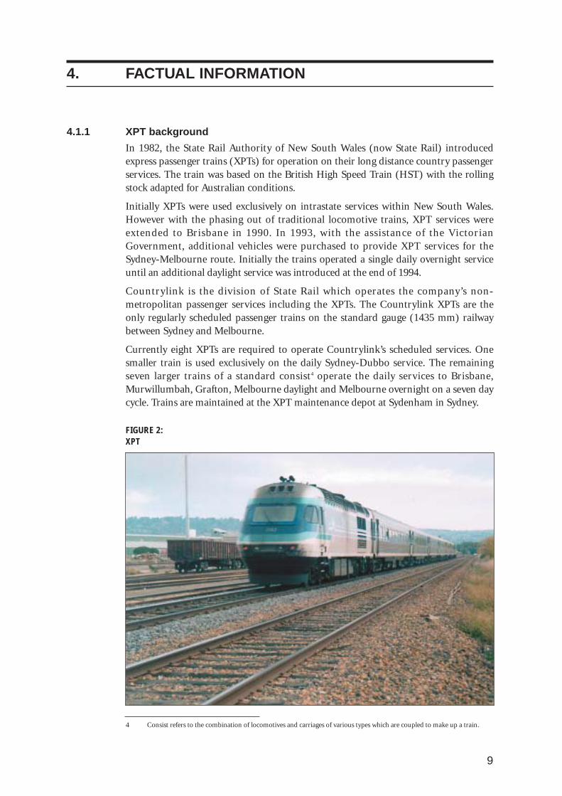
In 1982, the State Rail Authority of New South Wales (now State Rail) introducedexpress passenger trains (XPTs) for operation on their long distance country passengerservices. The train was based on the British High Speed Train (HST) with the rollingstock adapted for Australian conditions.
Initially XPTs were used exclusively on intrastate services within New South Wales.However with the phasing out of traditional locomotive trains, XPT services wereextended to Brisbane in 1990. In 1993, with the assistance of the VictorianGovernment, additional vehicles were purchased to provide XPT services for theSydney-Melbourne route. Initially the trains operated a single daily overnight serviceuntil an additional daylight service was introduced at the end of 1994.
Countrylink is the division of State Rail which operates the company’s non-metropolitan passenger services including the XPTs. The Countrylink XPTs are theonly regularly scheduled passenger trains on the standard gauge (1435 mm) railwaybetween Sydney and Melbourne.
Currently eight XPTs are required to operate Countrylink’s scheduled services. Onesmaller train is used exclusively on the daily Sydney-Dubbo service. The remainingseven larger trains of a standard consist4 operate the daily services to Brisbane,Murwillumbah, Grafton, Melbourne daylight and Melbourne overnight on a seven daycycle. Trains are maintained at the XPT maintenance depot at Sydenham in Sydney.
FIGURE 2: XPT
4 Consist refers to the combination of locomotives and carriages of various types which are coupled to make up a train.

10
4.1.2 Wodonga
The derailment occurred 301.105 km from Melbourne on the standard gauge mainline just outside the Wodonga Station yard between the High Street (300.951 km) andHovell Street (301.193 km) level crossings. The train continued west through thestation yard, towards Melbourne until brought to a stop with the lead power car atapproximately 300.022 km.
The rail services in Wodonga are provided by two systems with main lines, thestandard gauge (1435 mm) system, and the broad gauge (1600 mm) system. Thebroad gauge main line terminates at Albury Station and provides both passenger andfreight services from the Albury/Wodonga area into Victoria. The standard gaugemain line running through the Albury/Wodonga area provides interstate passengerand freight services between New South Wales and Victoria.
Both standard and broad gauge main lines run from Albury to Wodonga on a largelyparallel alignment. After passing the coal sidings at Wodonga, both main lines curve tothe west as they approach Wodonga Station and maintain a parallel alignment untilthey reach the Hovell Street crossing. At Hovell Street, the broad gauge main linecontinues in the constant radius curve, (800 m radius) until it crosses High Street.
The radius of the curve in the standard gauge main line between the Hovell Street andHigh Street crossings varies. Before the Hovell Street crossing the curve radius is 800 m which then decreases to 175 m over the crossing. This varation in curve radiuscauses the standard gauge main line to diverge from the broad gauge main line for ashort distance after the Hovell Street crossing and then reconverge just before the HighStreet crossing.
After the High Street crossing, the two main lines divide again as they approachWodonga Station. The broad gauge line enters the station to serve the single passengerplatform located on its northern side. The standard gauge main line runs through thestation yard in a curve to the south of the Wodonga Station buildings. As it passesthrough the station yard from the east, the standard gauge main line crosses thestation entry road and then a pedestrian crossing before it curves north to bring bothmain lines back onto a parallel alignment on the western side of the station. Bothmain lines continue west on a parallel alignment without any curves until they passout of the station yard at 300 km.

11
FIGURE 3:Wodonga aerial photograph
4.2 Sequence of events
4.2.1 The incident
At approximately 0755 on 25 April 2001 (ANZAC day), the Countrylink daylight XPTservice to Melbourne departed from Central Station in Sydney. The train consisted ofa lead power car followed by seven passenger cars designated from ‘A’ through to ‘G’and a trailing power car. On board the train was a crew of five- the driver, a passengerservice supervisor and three passenger attendants- and 127 passengers. The servicedeparted 12 minutes behind schedule, and as a result, could not use its tabled paththrough the Sydney metropolitan area. This resulted in further delays due to thesuburban commuter train traffic.
Once the train had left the Sydney area, it proceeded south without incident untilarriving at Junee Station at 1352. A driver change took place and during thechangeover the outgoing driver indicated to the incoming driver that the train was‘going OK’. The train left Junee at 1354 now 2 minutes behind schedule.
After leaving Junee, the train made stops at Wagga Wagga, The Rock, Henty andCulcairn before arriving at Albury. During the stop at Albury, the passenger servicesupervisor, senior passenger attendant and the two passenger attendants were relieved.The train moved from the Albury Station platform at 1532 and after stopping brieflyat the end of the platform to obtain authority to enter Australian Rail TrackCorporation (ARTC) territory, the driver accelerated to the line speed of 80 km/h.
After the train departed from Albury, one of the passenger attendants was having aconversation with the passenger service supervisor in the rear of car ‘G’. The passengerattendant then started walking through the train on his way to the buffet car. As he
Wodonga Station
Standard gaugemainline
Broad gaugemainline
Approx. pointof derailment
High Streetcrossing
Hovell Streetcrossing
Direction of travelfor service 8622
Wodonga Station
Standard gaugemainline
Broad gaugemainline
Approx. pointof derailment
High Streetcrossing
Hovell Streetcrossing
Direction of travelfor service 8622
NORTH
12
was passing through car ‘E’ he noted that the car was riding normally until heapproached the front of the car when he heard a loud ‘bang’ and felt the car drop whathe thought was approximately 150 mm. After this incident he felt the ride of the carreturn to normal and noted that the alignment of the diaphragm equipmentconnecting the cars was normal when he walked through into car ‘D’. At the time, thepassenger attendant attributed the ‘bang’ and ‘drop’ to the car ‘bottoming out’travelling over a dip in the track.
The driver maintained the train’s speed at 80 km/h until it was approaching theMelbourne end of the Wodonga coal sidings. He then allowed the train to coastwithout power and applied the brakes lightly at 1536. By the time the train waspassing the 40 km/h speed board just before the Osburn Street level crossing (301.611km), its speed was approximately 35 km/h. The driver allowed the train to coast pastthe Bandiana line turnout (301.630 km) and into the 800 m radius section of righthand curve prior to the Hovell Street level crossing (301.193 km).
Just after passing the Hovell Street level crossing, the driver moved the locomotivepower control to notch two to maintain the train’s speed through the curve. The traincontinued into the 175 m radius section of the curve. As the lead bogie of car ‘E’reached the 301.1086 km point in the curve, the inside wheel (number-2) on theleading axle dropped off the low rail. The wheel remained partly suspended with itsrim rubbing against the gauge face of the rail. At 301.105 km the number-2 wheeldropped completely from the low rail. At 301.10225 km, 2.75 m further on, the outerwheel flange (number-1) on the same axle climbed over the high rail. At 301.0911 km,11.15 m further on, the trailing wheel-set of the bogie also derailed with the outerwheel flange (number-3) climbing over the high rail and the inner wheel (number-4)dropping off the low rail into the track four-foot. The bogie was now completelyderailed with its two inner wheels running in the four-foot and its two outer wheelsrunning on the field side of the high rail.
As the lead power car passed through the High Street level crossing, (300.951 km) thecrew all recalled feeling the train ‘jerk’. The driver felt that the jerk may have been therear power car ‘shedding load’ (a reasonably common occurrence) and so he closedthe throttle and then re-applied power.
At this time, a pedestrian waiting at the south side of the High Street crossing, whohappened to be an ex-train driver, saw that lead bogie on car ‘E’ was derailed. Henoticed that the bogie was ‘bouncing around at a high frequency, about 3–5 times persecond’ and making a large amount of dust. He was concerned that the driver wasunaware that the train had derailed and so ran to the Wodonga Station platformwhere he remembered that there was a railway telephone. He found that the telephonehad been removed from its box and so ran further up the platform into the stationbooking office where he alerted the staff.
The passengers in car ‘E’ indicated that they heard a crunching sound around thistime and that the carriage started to fill with dust. They also indicated that the car wasriding very roughly and leaning over with luggage falling from the racks in thevestibule at the front of the car. They were alarmed and started to evacuate the car.The train was well inside the Wodonga Station yard by this time.
As the train approached the Wodonga ‘A’ signal box, the signalman in the box (whohad arrived early for work) heard the train making an abnormal noise. He looked outof the signal box window and saw that the train was making dust around the middleof the train. He thought that the train may be derailed and proceeded to call the driveron the train radio.

13
As car ‘E’ passed over the pedestrian crossing on the western side of the stationbuildings, the wheels of the derailed bogie running in the four-foot struck and liftedthe concrete block in the centre of the crossing. Soon afterwards, the air-conditioningunits which were fitted under the middle of the car, also struck the raised concreteblock pushing it along the track and off to one side. At this time the train crew recalledfeeling a second ‘jerk’ probably as the bogie wheels made contact with the concreteblock.
A passenger in car ‘E’ actuated the passenger emergency button at the Melbourne endof the car at this time.
The passenger service supervisor, in car ‘G’, and the driver both received the passengeremergency alarm. In response to the alarm, the passenger service supervisor made anannouncement on the crew address system instructing the passenger attendants tomake their way to their allocated cars to check which emergency button had beenactuated.
At approximately 1540, the driver received the radio call from the Wodonga ‘A’ boxsignalman at the same time as the passenger service supervisor’s call to the passengerattendants. Initially the signalman’s message was not clear to the driver, who was in theprocess of bringing the train to a stop in response to the passenger alarm. After he hadstopped, the driver called the signalman who indicated that he thought the train‘might be in the dirt’. The driver then looked down the train to see that the front of car‘E’ was out of alignment. He called the signalman back on the radio to indicate that itlooked as if he was right and that the train had derailed. The driver then dismountedfrom the driver’s cab to make an inspection.
The train was brought to a stop at approximately 300.022 km, 70 m before the HouseCreek bridge (299.952 km).
At this time, one of the passenger attendants was making his way through car ‘D’ andsaw passengers coming from car ‘E’ into the rear of car ‘D’. When he made his way intocar ‘E’, he noted that door diaphragm was misaligned and saw that there were nopassengers in the car. The car was filled with dust and some of the luggage racks in thevestibule had collapsed. The passenger service supervisor had also arrived at car ‘E’ bythis time and reset the passenger alarm. The train crew then proceeded to check thepassengers for injuries and reassure them.
After speaking with the driver on the radio, the signalman made contact with ARTCtrain control in Adelaide to indicate that the XPT had derailed and was stopped on themain line.
4.2.2 Subsequent events
At 1545, emergency service personnel from the police and fire brigade arrived at thescene.
By this time the driver had completed his inspection of the train and had ascertainedthat only the leading bogie of car ‘E’ was derailed. The driver made his way back to thedriver’s cab. As he entered the cab, train control was already trying to contact him onhis mobile telephone. He advised the train controller of the situation. The driver thenrang Countrylink in Sydney to inform them of what had happened. The driver and thepassenger service supervisor conferred at around this time with regard toarrangements for transhipping the passengers and arranging reliefs for the train crew.The driver indicated that Countrylink was organising road coaches for the passengers.

14
The fire service personnel during this time were inspecting the train for any risk offire. The police interviewed the driver and later breath tested him for the presence ofalcohol. The police also established a perimeter around the train. The Wodonga ‘A’box signalman, in conjunction with the police and other railway personnel, organisedfor the High Street, station entry and Kelly Street level crossings to be manned. Thesecrossings were causing road traffic delays with their boom gates down as a result of thetrain’s occupation of the track circuitry and damage in the case of the High Street levelcrossing.
Around this time, the passenger service supervisor arranged for the passengers to bemoved into the centre cars. He had conferred with the police and driver of the trainand the decision was made that the centre of the train offered the best place for thepassengers to disembark. The train crew also ensured that all of the passengersremained on the train as this was felt to be the safest and most comfortable place forthem to wait for the road coaches. The buffet car was opened and complimentaryrefreshments were provided to the passengers while they waited.
At 1636, the State Rail first response contractor at Cootamundra (Freightcorp) werecontacted by Junee train control and organised to attend the train and re-rail it. TheEDI staff at the track maintenance depot at Seymour were also notified and a fettlinggang was organised to attend the site to repair track damage so the line could bereopened. At 1650 a local signal fitter repaired some minor damage to the signalsystem at the High Street level crossing.
The road coaches arrived at 1715 and the passengers were transferred from the train tothe coaches without incident. Three V/Line conductors based in Wodonga had arrivedearlier to offer assistance and were used in conjunction with the XPT crew in thetranshipment. By 1740, the passengers and their luggage had been loaded aboard, andthe coaches dispatched for Wangaratta, Benalla and Melbourne.
At approximately 2030, the driver was relieved at the scene by another Countrylinkdriver and subsequently travelled to Melbourne by taxi, finally signing off duty at2400. After the passengers had departed, the passenger attendants and passengerservice supervisor stayed and cleaned the train until the three passenger attendantstravelled by taxi back to Albury and finally signed off duty at 2308. The passengerservice supervisor stayed on the train.
At 2106 the emergency response crew arrived and commenced re-railing car ‘E’. Thetrain was uncoupled between car ‘D’ and car ‘E’. The front half of the train was movedforward to allow the re-railing crew access to the front of car ‘E’. The leading bogie wasthen re-railed using hydraulic jacks and traversing equipment. By 2345, car ‘E’ hadbeen re-railed and the train was then re-coupled and inspected by engineers fromState Rail diesel services. The train was then cleared to proceed to Wodonga Loopwhere car ‘E’ was taken out of the consist and later shunted to a siding atapproximately 0230 on 26 April.
The remainder of the train was then re-coupled and cleared to depart for Alburyarriving at approximately 0320. The passenger service supervisor was relieved andsigned off duty at Albury. After departing Albury, the train returned to the XPTmaintenance depot in Sydney where it was inspected by NSW Department ofTransport officers and the Hasler tapes5 from the leading and trailing power cars wereimpounded.
5 Hasler tapes are the waxed paper event logs produced by the locomotive data recording equipment.
15
While the train was being re-railed, staff from ARTC and EDI had commenced workon examining the track and rectifying the damage. At 0120 the ARTC representativeon site declared the track open with a 15 km/h speed limit between 300 and 301 km.At 0202, an ARTC representative reinspected the track and extended the area of thespeed restriction to 302 km.
4.3 Injuries None of the 98 passengers and five crew on board train 8622 reported any injuries as aresult of the derailment. However, some passengers, particularly those in car ‘E’, whichderailed, were distressed by the derailment.
4.4 DamageThe lead bogie (NHA 198B) of car ‘E’, XF 2214, derailed at 301.105 km and ran alongthe track until the train stopped at approximately 300.140 km. Both the train and railinfrastructure in this section of the standard gauge main line sustained damage as aresult of the derailment.
4.4.1 Damage to the train
All wheels on the derailed bogie showed significant stone impact damage to flangesand treads as a result of running on the track ballast, over sleepers and otherobstructions (see figure 4). Some components of the bogie showed signs ofdamage/impact as a result of lateral and vertical over-travel while the bogie wasderailed:
• the outer end lateral control rod bushes were damaged,
• there were wheel rub marks on top of the brake hanger brackets on number-1 wheel,
• there were strike marks on the facing side of axle box guide bars on number-1 axle.
Other damage to car ‘E’ included:
• both refrigeration units slung under the carriage were damaged as a result of theimpact with the concrete block in the pedestrian crossing (figure 5),
• damage to water chiller refrigerant lines, and small hole in the carriage floor causedby the top of the primary suspension damper on number-1 wheel of the derailedbogie over travelling vertically,
• damage to the toilet holdover tank water fill line caused by derailed bogie over travel,
• a broken rubber stop on the coupling at the leading end on the car.
During the inspection a locating pin and some bearing material from a side bearerplate were found lying on the bolster between wheels 1 and 3 of bogie NHA 198B.Inspection of the side bearer plates and bogie bolster when the bogies were changedindicated that the locating pin originated from the side bearer plate adjacent to wheels1 and 3 of the bogie. Damage to the side bearer plate and its seat on the bolsterindicated that at some time the pin had been dislodged from the plate and becometrapped between the plate and the bolster (see figures 6, 7, 8).

16
FIGURE 4: Number-1 wheel showing damage to flange and tread
FIGURE 5:Damaged refrigeration units under carriage
FIGURE 6: Side bearer mounting surface on bogie bolster showing deformation around locating hole

17
FIGURE 7: Dislodged locating pin sitting on side bearer mounting surface in position of ‘best fit’ in thedeformation around its locating hole
FIGURE 8: Side bearer plate sitting on locating pin on mounting surface in the position of ‘best fit’ fordeformations on mounting surface, locating pin and side bearer plate
18
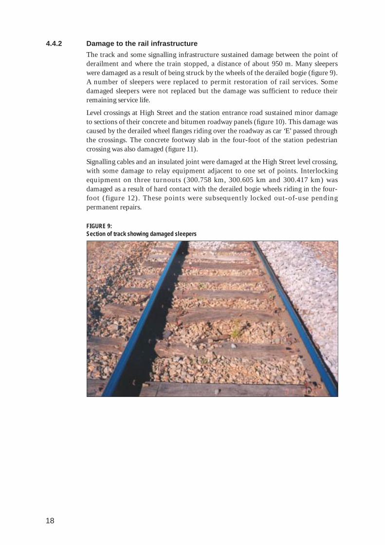
4.4.2 Damage to the rail infrastructure
The track and some signalling infrastructure sustained damage between the point ofderailment and where the train stopped, a distance of about 950 m. Many sleeperswere damaged as a result of being struck by the wheels of the derailed bogie (figure 9).A number of sleepers were replaced to permit restoration of rail services. Somedamaged sleepers were not replaced but the damage was sufficient to reduce theirremaining service life.
Level crossings at High Street and the station entrance road sustained minor damageto sections of their concrete and bitumen roadway panels (figure 10). This damage wascaused by the derailed wheel flanges riding over the roadway as car ‘E’ passed throughthe crossings. The concrete footway slab in the four-foot of the station pedestriancrossing was also damaged (figure 11).
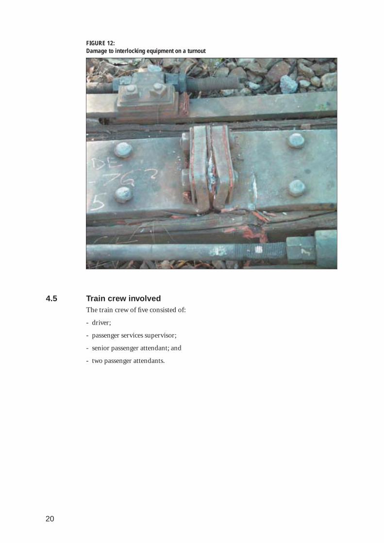
Signalling cables and an insulated joint were damaged at the High Street level crossing,with some damage to relay equipment adjacent to one set of points. Interlockingequipment on three turnouts (300.758 km, 300.605 km and 300.417 km) wasdamaged as a result of hard contact with the derailed bogie wheels riding in the four-foot (figure 12). These points were subsequently locked out-of-use pendingpermanent repairs.
FIGURE 9: Section of track showing damaged sleepers

19
FIGURE 10: Station entry level crossing showing damage to roadway
FIGURE 11:Pedestrian crossing showing impact damage to concrete slab in track four foot
20
FIGURE 12: Damage to interlocking equipment on a turnout
4.5 Train crew involvedThe train crew of five consisted of:
- driver;
- passenger services supervisor;
- senior passenger attendant; and
- two passenger attendants.

21
Table 1. Details of the XPT crew
Position Gender Classification Medical status Qualifications Time on duty prior to
derailment
Driver Male Locomotive driver Fit for duty Current 21⁄2 hours
Passenger Services Supervisor Male PSS Fit for duty Current 1 hour
Senior Passenger Attendant Male SPA Fit for duty Current 1 hour
Passenger Attendant 1 Male PA Fit for duty Current 1 hour
Passenger Attendant 2 Male PA Fit for duty Current 1 hour
Countrylink passenger services supervisors (PSSs) have the overall responsibility forservice delivery to passengers and supervision of the other three attendants. Inaddition, the passenger service supervisor undertakes certain safeworking duties underthe direction of the driver. The senior passenger attendant (SPA), assisted by thepassenger attendants (PAs), run the on-train refreshment services and perform otherpassenger related duties.
4.6 Train information
4.6.1 Train consist
The XPT train involved in the derailment was a standard seven car passenger consistwith leading and trailing power cars. The train has seating capacity for 360 passengers,a tare mass of 460 tonnes and a length of 204 m including the two power cars.
Table 2. Details of the train consist from the leading end
Car No Car ID Car Type Passenger seats Length Tare (m) (tonnes)
Power car XP 2016 Power unit Nil 17.3 76
A XAM 2182 Sleeping car 27 day/18 night 24.2 48
B XL 2228 First sitting car 56 24.2 48
C XBR 2156 Buffet car 21 + wheelchair position 24.2 44
D XF 2220 Sitting car 68 24.2 42
E XF 2214 Sitting car 68 24.2 42
F XF 2212 Sitting car 68 24.2 42
G XFH 2113 Luggage & sitting car 52 24.2 42
Power car XP 2008 Power unit Nil 17.3 76

22
4.6.2 Rolling stock date of build
The original XPT rolling stock was constructed by Commonwealth Engineering(Comeng) at its Granville factory between 1981 and 1982. Demand for the service andextension of the XPT routes necessitated the construction of more rolling stock in1983 and 1986. Further rolling stock was constructed by ABB Transportation inDandenong in 1993 when XPT services were extended to Melbourne.
4.6.3 Power cars
The train that derailed in Wodonga had diesel electric locomotives at each end of theconsist. The driver was operating the train from XP 2016, the leading power car, with XP 2008 as the trailing power car. XP 2008 was built by Comeng in 1982, withXP 2016 built by ABB in 1992. The control systems of the power cars are designed sothat the trailing power car acts as a ‘slave’ to the lead car. When the driver appliespower or braking in the lead car, the trailing power car receives similar commandssimultaneously. Train braking and auxiliary air may be supplied by either power car.Either power car may be used to supply train electrical power from its auxiliaryalternator.
Since 2000, State Rail have had an engine replacement program running. The originalValenta engines rated at 1477 kW are being replaced with new Paxman 12VP185 dieselengines which are rated at 1860 kW. XP 2016 was the first locomotive to be fitted withthe new engine. At the time of the derailment, XP 2008 was still fitted with an originalValenta engine.
4.6.4 Carriage XF 2214
FIGURE 13:Carriage XF 2214
23
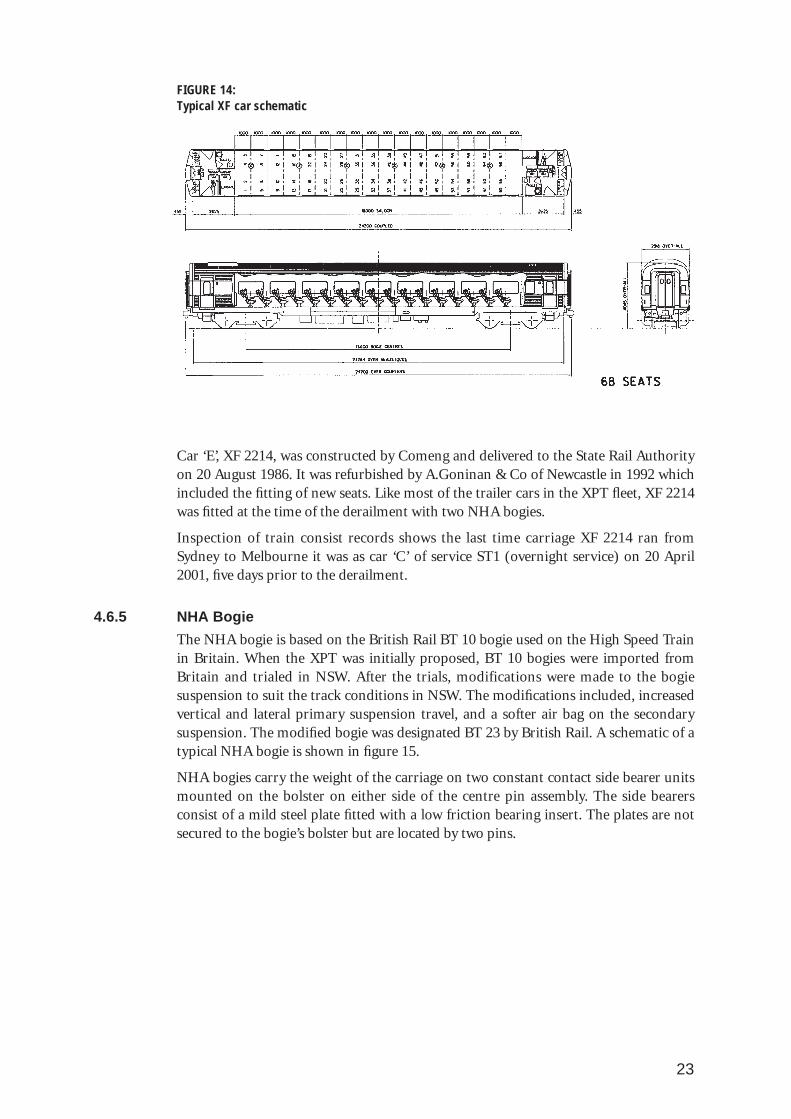
FIGURE 14:Typical XF car schematic
Car ‘E’, XF 2214, was constructed by Comeng and delivered to the State Rail Authorityon 20 August 1986. It was refurbished by A.Goninan & Co of Newcastle in 1992 whichincluded the fitting of new seats. Like most of the trailer cars in the XPT fleet, XF 2214was fitted at the time of the derailment with two NHA bogies.
Inspection of train consist records shows the last time carriage XF 2214 ran fromSydney to Melbourne it was as car ‘C’ of service ST1 (overnight service) on 20 April2001, five days prior to the derailment.
4.6.5 NHA Bogie
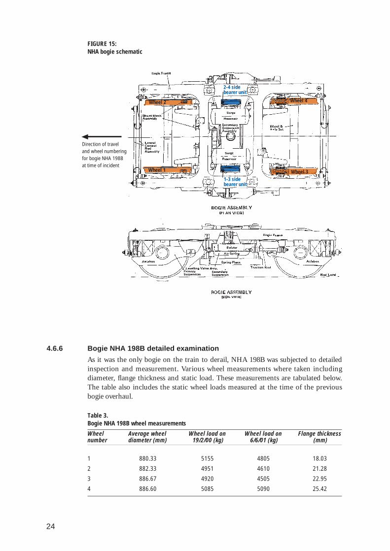
The NHA bogie is based on the British Rail BT 10 bogie used on the High Speed Trainin Britain. When the XPT was initially proposed, BT 10 bogies were imported fromBritain and trialed in NSW. After the trials, modifications were made to the bogiesuspension to suit the track conditions in NSW. The modifications included, increasedvertical and lateral primary suspension travel, and a softer air bag on the secondarysuspension. The modified bogie was designated BT 23 by British Rail. A schematic of atypical NHA bogie is shown in figure 15.
NHA bogies carry the weight of the carriage on two constant contact side bearer unitsmounted on the bolster on either side of the centre pin assembly. The side bearersconsist of a mild steel plate fitted with a low friction bearing insert. The plates are notsecured to the bogie’s bolster but are located by two pins.
24
FIGURE 15:NHA bogie schematic
4.6.6 Bogie NHA 198B detailed examination
As it was the only bogie on the train to derail, NHA 198B was subjected to detailedinspection and measurement. Various wheel measurements where taken includingdiameter, flange thickness and static load. These measurements are tabulated below.The table also includes the static wheel loads measured at the time of the previousbogie overhaul.
Table 3. Bogie NHA 198B wheel measurements
Wheel Average wheel Wheel load on Wheel load on Flange thicknessnumber diameter (mm) 19/2/00 (kg) 6/6/01 (kg) (mm)
1 880.33 5155 4805 18.03
2 882.33 4951 4610 21.28
3 886.67 4920 4505 22.95
4 886.60 5085 5090 25.42
Wheel 2
Wheel 1
Wheel 4
Wheel 3
2-4 sidebearer unit
1-3 sidebearer unit
Direction of traveland wheel numberingfor bogie NHA 198Bat time of incident

25
The wheel profiles show that the number-1 wheel flange was below the current StateRail condemning limit6 of 19 mm. Figure 16 is the profile of number-1 wheel after thederailment overlaid on the standard TP2 profile. Wheel diameter measurementsindicate that number-1 wheel was the smallest on the bogie and 2 mm smaller thannumber-2 wheel. Current in-service dimensional tolerance for the diameter of wheelson the same axle is 1 mm variation.
FIGURE 16: Number-1 wheel and TP2 profiles
The geometry of the bogie frame and spring plank were also checked. Trammelling7
revealed that the bogie frame was absolutely square. The spring plank and bogie framewere also placed on a level table and measured using a straight edge and dumpy levelrespectively. These tests revealed both parts were within acceptable limits, 3 mmvariation for the spring plank, and 2.5 mm maximum variation for the bogie frame.
Static wheel loads are measured when bogies are overhauled using a purpose-built jig.The bogie is placed on the jig and is pulled down using a hydraulic jack acting on thecentre pin housing in the bolster. Individual wheel loads are measured and adjusted asnecessary during the overhaul by packing the primary suspension springs. Theallowable load variation is 400 kg per wheel or axle total based on a total bogie load of19.6–20.4 tonnes. From the tabulated results, bogie NHA 198B was within thetolerance at the time of the last overhaul and just outside on individual wheel variationwhen measured after the derailment. It was also determined that the number-1 wheelwith the most tread wear and thinnest flange also had the highest static load whentested at the time of the last overhaul.
4.6.7 Rolling stock maintenance
The XPT rolling stock is maintained by State Rail using a planned maintenance andcondition monitoring program. A trip inspection is carried out each time a trainarrives at the Sydenham maintenance depot with more comprehensive inspections andmaintenance carried out every 90 days. There are 10 different maintenance levels,which include running and trip inspections and eight different 90-day maintenance
6 Condemning limit is a designated flange thickness below which the wheel is considered to be unserviceable
7 Tramelling is the measurement of the distance between two fixed points with a calibrated gauge similar in principle to abeam compass
Design TP2 wheel profile
Number-1 wheel

26
levels designated A–H. The maintenance regime is largely based on manufacturer’srecommendations and is modified when condition monitoring dictates the need tofocus more effort on specific items.
Maintenance scheduling and recording is facilitated by a computer based maintenanceprogram. Regular inspections and maintenance tasks are performed usingstandardised and documented procedures. Each inspection or maintenance task isdivided into a number of trade specific parts and an inspection sheet is issued for eachdifferent trade (mechanical, electrical, car and wagon examiners, plumbers, carbuilders and trimmers). The inspection sheets provide specific instructions on how toperform the maintenance and include a checklist, which must be completed andsigned off by the tradesmen performing the maintenance. After a maintenance task iscompleted, the entries on the inspection sheets are entered into the computerisedmaintenance program.
Maintenance records show that the train involved in the derailment underwent a tripinspection on 24 April 2001 after arriving at the XPT maintenance depot oncompletion of the NT2 service from Brisbane. The trip inspection included a wheelexamination (not including flange thickness measurement) and examination ofvarious components of the trailer car bogies including the frame, axle box assemblies,air springs, lateral control rods and safety straps. There were no abnormalities notedduring this inspection.
The maintenance records also show that carriage XF 2214 underwent a schedule ‘F’ 90day inspection on 10 April 2001. This inspection also included a wheel inspection anda detailed inspection of the bogies including the condition of the radial wear plates(side bearer plates). Once again, there were no abnormalities noted at this time.
4.6.8 Wheel flange monitoring
In addition to other programmed maintenance, wheel flange thickness is regularlymonitored on XPT rolling stock. Wheel-sets are machined on an underfloor lathe (atDELEC in Enfield) when flanges reach a pre-determined wear limit or the wheelsdisplay other faults which need rectification. In order to restore a full thickness flange,wheels may have up to 15 mm machined from their diameter. The geometry of theXPT wheels generally allows each wheel-set two full turns to restore a full flangebefore the wheel diameter condemning limit is reached. Wheel-sets are changed oncethe wheels have reached their condemning limit on diameter and flange wear. Onceany wheel on either bogie on a carriage has reached this point, the carriage is liftedand both bogies are changed as a pair. The bogies are then fitted with new wheel-setsor overhauled completely depending on the ‘frame’ kilometres run.
Maintenance records for carriage XF 2214 show that both bogies (NHA 198B and56B) were overhauled as a pair on 22 February 2000 and had their wheel-setsmachined to provide full thickness flanges on 13 May 2000 and 7 November 2000respectively.
Flange thickness records for bogie NHA 198B are tabulated below. The records showthat the last time the wheel flanges were measured prior to the derailment was on 15 March 2001, approximately six weeks before. The records show that wheel number-1 was the most worn with 8 mm of wear making the flange 21.7 mm thick based on afull flange thickness of 29.7 mm.

27
Table 4. Bogie NHA 198B wheel flange measurements
Date of measure Wheel number/flange wear (mm)
1 2 3 4
Overhauled 22/02/005/03/00 1 1 1 12/04/00 3 3 2 21/05/00 4.5 4 2.8 2.8
Re-machined 13/5/0026/05/00 0.8 0.8 1 012/07/00 4.2 4 3 1.8
13/08/00 5.5 5 4 2.8
10/09/00 6 5.5 4.2 2.8
6/10/00 7.8 7 5 3.5
2/11/00 10 8 6 4
Re-machined 7/11/00
12/12/00 0 0 0 0
15/01/01 6 5.5 3.5 4
16/02/01 8 6 5 4
15/03/01 8 7 5.5 4
4.7 Track details
4.7.1 Background
The location of the derailment was established at 301.105 km (from Melbourne), eastof Wodonga railway station yard between the Hovell Street and High Street levelcrossings on the standard gauge interstate corridor between Melbourne and Sydney.The track is sharply curved to the right in the direction of travel. The grade of thetrack is 1 in 75 climbing in the direction of travel. The posted train speed limit for alltypes of trains on the curve is 40 km/h.
The track in this area was laid as part of the 1959–1962 Wodonga-Melbourne standardgauge rail project. The new standard gauge main line was routed around the WodongaStation to keep the main line clear of the existing broad gauge facilities. At the time,there was a broad gauge crossing of the standard gauge line just east of the High Streetlevel crossing for the broad gauge line to Bandiana-Tallangatta-Shelly. As this line isnow closed, the diamond crossing was removed in December 1997.
Figure 17 is an excerpt from Victorian Rail Track’s plan of the Wodonga Coals Sidingsshowing the area of the derailment. The plan shows the original diamond and turnoutto Bandiana, removed in 1997.

28
FIGURE 17:Excerpt from Wodonga coal sidings railway plan showing area of derailment
4.7.2 Track specification
The track details for the standard gauge main line in the area of the derailment are asfollows:
• Rail 47 kg/m, welded up to 82 m lengths.
• Timber sleepers 2590 mm x 254 mm x 127 mm, hardwood.
• Sleeper spacing 685 mm nominal.
4.7.3 Track geometry
The design geometry details of the Wodonga curve where the derailment occurredwere obtained from the 1995 Victorian Public Transport Corporation curve register.
Table 5. Curve register details
Location Hand Radius Alignment Curve cant Cant(km) max/min Transition Max Transition
(m) (m) (mm) (m)up down up down
301.060-301.190 L 175/175 0 50 40 25 50
301.190-301.280 L 800/800 50 40 50
301.280-301.630 L 300/350 35 40 25
Diamond (now removed)
Old Bandiana lines
Diamond (now removed)
Old Bandiana lines
29
4.7.4 Track gauge and cross-level
Selected measurements of the track gauge and cross-level (height difference betweenhigh and low rails) taken after the derailment by officers from ARTC are tabulatedbelow.
Table 6. Gauge and cross-level measurements around point of derailment
Station Approx km Cross-level Gauge Station Approx Cross-level Gauge(mm) (mm) km (mm) (mm)
1 301.126 60 +1 11 301.106 37 +20
2 301.124 60 +10 12 301.104 34 +5
3 301.122 55 +12 13 301.10225 31 +2
4 301.120 54 +3 14 301.100 35 0
5 301.118 43 +20 15 301.098 20 +10
6 301.116 50 +5 16 301.096 15 +5
7 301.114 50 +10 17 301.094 0 +5
8 301.112 45 +15 18 301.092 0 +3
9 301.110 45 +18 19 301.090 0 +3
10 301.108 37 +15 20 301.088 0 0
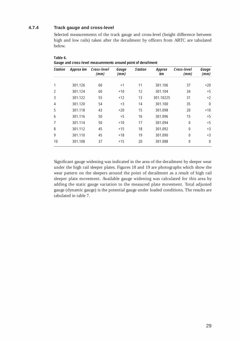
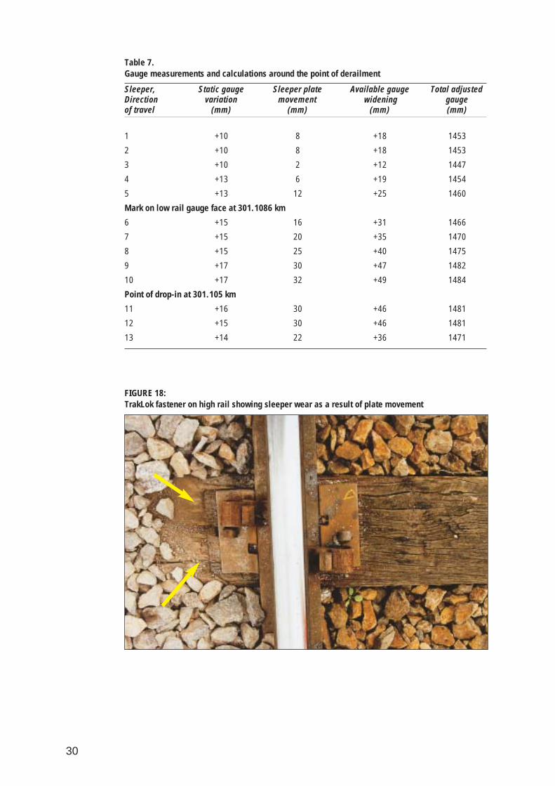
Significant gauge widening was indicated in the area of the derailment by sleeper wearunder the high rail sleeper plates. Figures 18 and 19 are photographs which show thewear pattern on the sleepers around the point of derailment as a result of high railsleeper plate movement. Available gauge widening was calculated for this area byadding the static gauge variation to the measured plate movement. Total adjustedgauge (dynamic gauge) is the potential gauge under loaded conditions. The results aretabulated in table 7.
30
Table 7. Gauge measurements and calculations around the point of derailment
Sleeper, Static gauge Sleeper plate Available gauge Total adjusted Direction variation movement widening gauge of travel (mm) (mm) (mm) (mm)
1 +10 8 +18 1453
2 +10 8 +18 1453
3 +10 2 +12 1447
4 +13 6 +19 1454
5 +13 12 +25 1460
Mark on low rail gauge face at 301.1086 km
6 +15 16 +31 1466
7 +15 20 +35 1470
8 +15 25 +40 1475
9 +17 30 +47 1482
10 +17 32 +49 1484
Point of drop-in at 301.105 km
11 +16 30 +46 1481
12 +15 30 +46 1481
13 +14 22 +36 1471
FIGURE 18: TrakLok fastener on high rail showing sleeper wear as a result of plate movement
31
FIGURE 19:Measuring plate movement on a Pandrol fastening fitted to the high rail the point of derailment
4.7.5 Alignment
The design radius of the curve in the area of the derailment is 175 m. It was thesharpest section of curve in the standard gauge main line between Sydney andMelbourne. The alignment of this section of the curve was governed at the time ofconstruction by the presence of the broad gauge diamond which has subsequentlybeen removed. There has been no work since the removal of the diamond to improvethe alignment of the curve.
Measurements taken after the derailment showed a curve radius of 200 m then asignificant sharpening of the curve in the direction the train travelled to 174 mapproaching the point of drop-in. There was no alignment transition from straighttrack to the 174 m radius section of the curve at its Melbourne end. Figure 20 is aphotograph of the curve where the derailment occurred looking towards the HovellStreet crossing, the standard gauge mainline is on the right.

32
FIGURE 20:Curve where the derailment occurred
4.7.6 Rail
The rails at the derailment site were the original 47 kg/m rail stock laid in 1959/61.Rail wear on both high and low rails was modest with the gauge face of the high railshowing 8 mm wear.
4.7.7 Sleepers
Since this section of the line was laid, sleepers have been replaced principally duringmajor sleeper renewal, at approximately five year intervals. The sleeper renewalsconducted at these times were condition based. VicTrack provided the followingVictorian PTC records for sleeper renewals in the Benalla to Wodonga maintenancearea tabulated below.
Table 8. PTC sleeper replacement records
Start Finish Start Finish Distance Sleepers Density Averageweek week km km km total Sl/km ratio
23/8/80 4/4/81 194.388 304.166 109.778 26461 241 1:6
2/2/85 21/6/86 192.300 304.000 110.600 46190 418 1:3.5
21/4/90 9/6/90 195.000 304.000 109.000 27772 255 1:5.7
2/9/95 21/10/95 233.300 304.100 69.800 20838 299 1:4.9
As part of the resilient fastening project in 2000, 22 sleepers were renewed between301–301.1 km and 1 sleeper was renewed between 301.1–301.2 km in January 2000.These are the only records of sleeper replacement since 1 July 1998 when ARTC tookover the lease on the line. Figure 21 shows the condition of some sleepers in the curvewhere the derailment occurred and the ballast profile on the field side of the high rail.

33
FIGURE 21:Sleepers and ballast in the area of the derailment
4.7.8 Fastenings
The rail fastenings in the area of the derailment were a mixture of configurations. Onthe low rail of the curve the rail was held at each sleeper by a pair of Rex-Lok-Ins. TheRex-Lok-In system consists of a stud that is hooked into the dog spike hole of theexisting sleeper plate and a spring clip (B296) fitted to the stud which exerts constantpressure on the toe of the rail. Each sleeper plate was fastened to the sleeper by twospring (lock) spikes.
The high rail had a variety of fastenings consisting of cast iron Pandrol sleeper platesfitted with ‘E’ clips and TrakLok (Rex-Lok-Ins) mounted on double shoulder sleeperplates. The Pandrol sleeper plates were fastened to each sleeper using two screw spikeswith the TrakLok plates fastened by two spring spikes. The table below shows the highrail fasteners and their disposition as recorded by ARTC officers after the derailment.

34
Table 9. High rail fastener disposition after derailment
Sleeper Plate Dynamic High rail Spike type and disposition, (dimensions in mm)movement gauge fastener
(mm) (mm) type Inside Outside
1 5 +15 Pandrol Screw, down, skewed Screw, down, skewed
2 8 +18 TrakLok Spring, down Spring, down
3 8 +18 TrakLok Spring, down Spring, down
4 2 +12 Pandrol Screw, up 20, skewed Screw, up 20, skewed
5 6 +19 TrakLok Missing Spring, up 30
6 12 +25 TrakLok Spring, up 20, skewed Spring, up 40
Mark on low rail gauge face at 301.1086 km
7 16 +31 Pandrol Screw, up 20, skewed Screw, up 20, skewed
8 20 +35 TrakLok Spring, down Spring, up 15
9 25 +40 TrakLok Spring, up 70 Spring, up 40
10 30 +47 Pandrol Screw, up 10, skewed Screw, up 15, skewed
11 32 +49 TrakLok Spring, up 60 Missing
Point of derailment 301.105 km
12 30 +46 TrakLok Spring, up 90 Spring, up 50
13 30 +46 Pandrol Screw, up 20 Screw, up 20
14 22 +36 TrakLok Spring, up 30 Spring, up 20
Both Pandrol and TrakLok fasteners are designed to exert constant pressure on the toeof the rail. In the case of the TrakLok system nominal toe load is of the order of 9 kNfor each clip and for the Pandrol fasteners 8.6 kN per clip.
4.7.9 Ballast profile
In the area of the derailment the ballast profile is crushed stone typical of main linesize. The top most ballast was clean and free draining but the lower material showedsigns of fouling. Ballast had been discharged on the shoulder of the curve in February2001 in preparation for track rectification works including tamping. At the time of theincident, the ballast had not been tamped or regulated in the area of the derailmentand there was ballast covering the sleepers and fastenings on the field side of the highrail.
4.7.10 Lubrication
At the time of the derailment a lubricator was fitted to the high rail on the Melbourneend of the curve. The lubricator was fitted to provide grease to the gauge face of thehigh rail throughout the curve where the derailment occurred. It was apparent oninspection after the derailment, that the lubricator had been inoperative for some timeas the gauge face of the high rail exhibited a bright rough surface (figure 22). Theplucking and pitting of the gauge face indicated a high rate of local wear consistentwith a lack of lubrication. In addition there were fresh metal flakes lying on the insidetoe of the rail throughout the 175 m radius section of the curve.

35
FIGURE 22: High rail gauge face showing wear from lack of lubrication
4.7.11 Infrastructure maintenance
The standard gauge main line in Victoria, formerly owned by the Victorian PublicTransport Corporation (PTC) is now owned by VicTrack. On 1 July 1998, ARTC tooka long-term lease on the standard gauge rail infrastructure on the interstate corridorsfrom Wolseley to Melbourne and Albury. Up to this time all maintenance on the railinfrastructure had been performed by the Victorian PTC. After leasing the track,ARTC set up an alliance contract with Asea Brown Boveri (ABB) to maintain theVictorian standard gauge infrastructure under their control. ABB subsequentlyemployed many ex-PTC staff who had had previous experience maintaining the track.In 2000, ABB’s rail infrastructure maintenance division was purchased by EvansDeakin Industries Pty Ltd (EDI) and now forms part of their Powerlines,Telecommunications and Rail (PTR) division. The ARTC maintenance contract wascontinuous during the change of ownership from ABB to EDI, with the PTR divisionproviding the same contracted service with the same employees and equipment.
EDI’s responsibilities under the provisions of the alliance contract are the day-to-daymaintenance, emergency maintenance, and condition monitoring of the trackinfrastructure. ARTC run larger infrastructure works as projects and let contracts via atender process for these works. Such projects on the Victorian standard gauge systemrecently have included: rail resilient fastening and re-sleepering and track rectificationworks including rail straightening, grinding, tamping, ballast cleaning and regulation.
The agreement between ARTC and EDI stipulates that the track in Victoria is to bemaintained to the standards contained in the Victorian Public TransportCorporation’s civil engineering circulars (CECs).
EDI maintenance staff, responsible for the track maintenance in the Wodonga area,stated that they based their maintenance and condition monitoring on the geometry

36
standards specified in CEC 8/86 with reference to CEC 7/86 for track recording caroperations.
ARTC monitor the performance of their track maintainers by periodic spot checks ofmaintenance records and track condition. In addition, some of EDI’s Victorianmaintenance management staff are co-located with ARTC staff in Melbourne.
4.7.11.1 Track patrolsEDI maintenance staff patrol the standard gauge main line between Benalla andAlbury five times a fortnight using Hi-Rail vehicles (conventional road vehicles fittedwith rail wheels that may be lowered onto the track). The last patrol of the area of thederailment was the day before, or Tuesday 24 April 2001. The track inspectors did notnote anything unusual during this inspection in the area of the derailment.
4.7.11.2 Front-of-train inspectionsOnce a month the EDI section maintenance supervisor travels in a locomotive overhis section of track. The purpose of these inspections is to assess track condition basedon the ride of the train with some input from the driver. The last front-of-traininspection, prior to the derailment, of the Wodonga area was on 1 April 2001. Thearea maintenance supervisor did not note anything unusual during this inspection inthe area of the derailment.
4.7.11.3 Track recording carTrack recording cars are routinely used to record track geometry throughout theARTC standard gauge network. Recording cars have the advantage of measuring trackgeometry under dynamic conditions of load and thus may detect defects which maynot be apparent to maintenance staff performing Hi-Rail inspections. The trackrecording car is equipped with trolleys, fitted with measuring transducers, which ridethe track and measure the following geometric parameters:
• track gauge,
• surface irregularities (top), each rail separately,
• alignment (line), each rail separately,
• superelevation (cant),
• short twist,
• long twist.
The car is also equipped with a computer and statistical analysis software, which maybe used to calculate various track geometry indices including track quality and ride.The recording car is able to quantify the observed condition of the track and compareit to specified standards. Its primary functions are to:
• highlight track faults that require corrective action by local maintenance crews.These faults are categorised and may be of high, medium or low priority,
• provide information for planning major scheduled maintenance by comparingresults over time,
• comparison with other sections of track for setting maintenance priorities.
Since 1995, the ARTC standard gauge main line geometry has been recorded undercontract by an EM80 track recording vehicle based in Adelaide. This vehicle is ownedand operated by the Rail Infrastructure Corporation formerly Rail Services Australia.

37
The track recording car is scheduled to record the Melbourne-Albury standard gaugemain line every three months. The last recording car run in the Wodonga area prior tothe derailment occurred on 28 February 2001. The previous two recording car runs inthe area were on 30 November 2000 and 31 August 2000.
The track geometry in the area of the derailment was not recorded during theFebruary 2001 or November 2000 runs as a result of automatic measuring trolley lifts.An automatic trolley lift occurs during a recording run when the trolley experiences anabnormal ‘event’. The measuring trolley is automatically lifted from the track toprotect the measuring equipment. As the trolley is no longer in contact with the rails, asection of track is not recorded, the length of the section being dependent on the timetaken to bring the car to a stop to reset the trolley. Common causes of trolley lifts arean object on the track, a level crossing, or a turnout. Trolley lifts may also be caused bytrack faults that have the potential to cause a train derailment such as excessive gauge.
When a trolley lift occurs, the recording car is stopped and the equipment checked andreset. Standard operating procedures dictate that the preceding section track must beinvestigated at the time by track maintenance staff to ascertain the cause of the trolleylift. When a trolley lift occurs, a report is also issued to the area maintenancesupervisor on the car, which details:
• date,
• location,
• which trolley lifted,
• direction of Travel,
• speed of EM80,
• track type,
• track features,
• track components,
• parameters identified as exceedences, their maximum value and safe speed,
• cause and track defects identified,
• comments,
• actions taken.
The 28 February 2001 trolley lift report indicated that the leading trolley lifted at301.120 km while the recording car was travelling at 25 km/h. There were noparameter exceedences at the lift point entered in the report. The comments sectionstates: ‘Very tight curve – large line values. (Also refer Nov 00)’. The 30 November 2000trolley lift report indicates that the leading trolley lifted at 301.100 km with no vehiclespeed entered, no parameter exceedences entered and no comments.
4.8 Train controlThe train control system on the standard gauge main line in the Wodonga area isCentralised Traffic Control. The operations of signal and points are controlled fromthe ARTC train control centre in Adelaide.
When required, local standard gauge operations can be controlled by switching in theWodonga ‘A’ signal box. The signal box is operated by Freight Australia. This usuallyoccurs when shunting operations are being performed, generally for freight. The

38
Wodonga signal box may also be switched in to provide local train control in anemergency as was the case with the XPT derailment, where some signalling equipmenthad been damaged.
No technical defects or operational issues concerning train safeworking or controlwere found that may have contributed to the derailment.
4.8.1 Other traffic
Records obtained from train control indicate on 25 April 2001 the three trains whichtraversed the derailment site prior to XPT service 8622 were: National Rail’s freightservice 9602, southbound arriving at Wodonga at 0456; Freight Australia’s freightservice 9681, northbound arriving at Wodonga at 0558; and Countrylink’s passengerservice 8611, northbound arriving at Wodonga at 1122. There were no records ofanything abnormal being reported by these services in the area of the derailment.
4.9 Environmental factorsThe derailment occurred during daylight hours. Weather observations from theBureau of Meteorology indicate that the day was fine with the temperature in the areaat the time of the derailment approximately 17°C, the maximum temperature for theday was recorded as 17.6 °C at 1500. Wind was from the north-north-west at 9 km/h.Weather is not considered to be a contributing factor.
4.10 Recorded information
4.10.1 Train control
Recorded information from ARTC Train Control Centre in Adelaide, indicated thatAuthorities had been issued correctly and in accordance with prescribed procedures.
The train control centre also provided the investigation with copies of the majorincident log, the train control report detailing the incident, and the notifications ofthe incident to the Victorian Department of Transport-Rail Safety Section andComcare Australia. The incident log and notifications were issued in accordance withARTC’s ‘Interface Procedure, Incident Management Plan, Document TA44’.
4.10.2 Locomotive data recorders
XPT locomotives are equipped with Hasler event recording hardware. Parameters arerecorded on a waxed paper roll by four stylii which continuously record time, speed,power circuit status, and brake cylinder pressure. Vigilance acknowledgment is alsorecorded on the power circuit trace. It is a requirement that the Hasler equipment isrecording any time the locomotive is being operated, with the waxed paper chartsbeing routinely changed each time the locomotive arrives back at the XPTmaintenance depot.
The Hasler event recording tapes from the leading and trailing locomotives on thetrain were impounded by officers from the NSW Transport Safety Bureau when thetrain arrived back at the XPT maintenance depot in Sydenham at 1200 on 26 April.The tapes were held in safe keeping at the office of the NSW Transport Safety Bureau.On 4 May, the tapes were analysed by a representative from Countrylink in thepresence of a Transport Safety Officer from the NSW Transport Safety Bureau. The
39
Countrylink officer produced a report of his analysis of the Hasler tapes. The followingis an excerpt from that report:
Event Recording tapes from both power cars on the consist, being XP2016 leading vehicle,and XP2008 the rear power car on the train consist were read and analysed.
The method of reading the tapes were to overlay them on a master sheet, which is printedwith major locations, kilometrage from Sydney, and maximum speed at documentedlocations, and conduct a comparison between what is the maximum permitted speed on themaster sheet, and the actual recorded speed displayed on the tape. Time, power circuit andbraking zones are not printed on the master sheet. They can be aligned to the speed byreading all at any given point on the tape in a vertical line.
The readings show that:
• There is a 1 minute differential between the clock settings on the two tapes.
• The tape extracted from XP2016 gave a compressed reading, which displayed a shorterdistance travelled, due to tight operating mechanism in the recording machine.However, careful analysis and comparison with speed line recordings on the tapeextracted from XP2008, which practically matched the master sheet, definitiveconclusions could be reached.
• The power circuit status trace displayed on the tape extracted from XP2008 did notrecord correctly.
• The service departed Junee at 1352 hours
• It stopped at Wagga from 1414-21 hours
• It stopped at the Rock from 1436-39 hours
• It stopped at Henty from 1452-53 hours
• It stopped at Culcairn from 1504-05 hours
• It stopped at Albury from 1528-32 hours
• The driver operated the service within the required speed and operational parametersover this part of the journey.
Following departure from Albury:
• The service travelled a distance of 200 metres and then stopped for a period of oneminute.
• After moving the service accelerates to achieve a speed of 80 kilometres per hour aftertravelling a distance of 2.8 kilometres.
• It then coasts at a speed of 80 kilometres per hour for a distance of 1.2 kilometres beforereducing speed.
• At 1536 hours, a light application of the brakes is noted, and over a distance of onekilometre the speed of the train gradually reduces to 25 kilometres per hour.
• Power circuits are then activated and after a distance of 200 metres the speed is 35kilometre per hour.
• At 1540 hours a heavy application of brake cylinder pressure is noted, together with thepower circuits opening and speed rapidly falling to zero. All occurring over a distance of100 metres.
• The service then stands at this location from 1540 hours until 0118 hours. Movementconsistent with shunting is then noted.

40
Conclusion
Evidence on the Hasler recording tapes used on this service display that the driver of theservice operated the service within required speed parameters for the route.
Evidence also indicates that the operation of power and braking apparatus was consistentwith correct driving practice.
A section of the Hasler speed trace is reproduced in figure 23. It shows, among otherthings, two points in the speed trace which corroborate the train crew’s statementswith regard to the ‘jerks’ they felt around the time of derailment.
FIGURE 23:Excerpt from Hasler speed trace
4.11 Site informationThe schematic diagram shown in figure 24 provides general details of key locations atthe derailment site.
FIGURE 24:Derailment site
ALBURY
Approx. point of derailment
impact at pedestrian crossing
TRAIN STOPPED AT 300.022 KM
Broad gauge main line
Hovell Streetcrossing301.193 km
Standard gaugemain line
High Streetcrossing300.951 km
Bogie fully derailed301.0911 km
Point of derailment301.105 km

41
4.12 Medical issues and toxicologyThe driver of 8622 underwent a breath test for the presence of alcohol by personnelfrom the Victorian Police who attended the scene shortly after the incident. The resultwas negative.
The Adelaide Train Controller was breath tested by authorised personnel at the ARTCTrain Control Centre shortly after the incident. The result was negative.
4.13 Tests and researchTechnical analysis of the derailment was provided for the investigation by the technicalanalysis unit of the ATSB and two companies with expertise in rail investigation,Weltrak Pty Ltd and Interfleet Technology Pty Ltd.
4.13.1 ATSB technical analysis
The ATSB technical analysis unit were provided with the side bearer plates from bogieNHA 198B and the mating plates from the carriage. The locating pin and bearingmaterial found lying on the derailed bogie bolster, were also passed to the unit foranalysis. The primary objective was to try to establish when the locating pin becamelodged between the side bearer plate and the top of the bogie bolster.
The following is a summary of the substantive findings of the technical analysis:
• The locating stud of the left side bearer plate (1–3 side bearer plate) became trappedbetween the plate and bogie top member during abnormal bogie motions during thederailment.
• The threaded connection between the stud and plate had been affected by oxidation.
• Regions of thread damage on the stud did not display bright metal surfaces. Itappears that the damaged thread had been oxidised.
• It was very evident that the friction material included in the bearer plate assemblyhad worn to a degree that contact between the elements of the assembly hadoccurred through metal to metal contact.
• It was evident that metal to metal contact had occurred in other bearer plateassemblies from the XPT carriage.
• Operation of bearer plate assemblies with metal to metal contact (excessively wornfriction material) will result in heating. Frictional heating will result in the oxidationof steel components.
4.13.2 Weltrak analysis
Weltrak Pty Ltd was contracted to provide the ATSB with services including:
• Provide expert analysis of track at the site of the derailment including gauge,geometry, condition, lubrication, construction and comparison with existingstandards.
• Provide expert analysis of rolling stock/track interaction with view to establishingthe mechanism(s) of derailment.
• Provide expert assistance with assessing track maintenance and constructionstandards and procedures.
• Provide expert analysis of track maintenance history at derailment site.

42
• Report to ATSB investigation team findings with respect to both the track in thevicinity of the derailment and the derailed bogie.
The substantive points of Weltrak’s analysis of the incident are set out in brief below.The complete Weltrak report is reproduced in appendix 1.
4.13.2.1 Track analysisWith respect to the track in the area of the derailment Weltrak found:
Track gauge
• The gauge widening, around the point of drop-in, of the magnitude indicated by theARTC measurements after the derailment, is a serious defect warranting immediaterepair once found.
• Wide gauge of this magnitude develops over many months with the growth likely tostart slowly and ultimately become exponential.
Alignment
• The alignment of the curve where the derailment occurred was governed by thepresence of the broad gauge crossing diamond removed in 1997.
• The design radius of 175 m is not suitable for the operation of the current types ofinterstate trains and is certain to result in high levels of deterioration compared toother parts of the line.
• The absence of any transition from straight track to the 175 m radius on theMelbourne end of the curve can be expected to result in alignment deteriorationunder heavy trains with hot weather exacerbating the problem further.
• Alignment problems in the curve were inevitable.
• The ARTC stringline data taken on 4 May 2001 shows curvature as little as 147 mfollowing the track repair work after the derailment. It is of some concern thatalignment this sharp was left in the main line even with the 15 km/h speedrestriction.
Cross-level
• The change in cross level up to the point of drop-in is not excessive with no loss ofvertical wheel load likely for the XPT rolling stock.
Rail
• The wear on both the high and low rails is modest. The wear on the high rail isconsistent with regular deflection of the head of at least 3 mm. The low wear and thestiffness of the rail section means that the deflection is achieved by roll of the railunder load.
Sleepers
• The appearance of the sleepers in the area of the derailment would indicate thatmany were 18 to 20 years old. The condition of these older sleepers was not goodwith many showing, splitting, worn spike holes, rot and back cant wear.
Fastenings
• All sleepers in the vicinity of the derailment showed evidence of high rail platesbeing regularly pushed outward, adding up to 32 mm rail play to the static trackgauge.

43
• The use of four spring spikes is appropriate for the Rex-Lok-In system in curves ofradius 300 m or less.
• There were insufficient spikes to resist lateral forces and effectively hold the sleeperplate in place on the sleeper.
• There was play also present at the sleeper plates fastened with screw spikes. With thefailure (movement) of the other plates, large loads are transferred to the strongerfastenings which fail as a result.
Ballast
• The shoulder ballast which was found to be covering the ends of the sleepers andfastenings on the outside of the high rail in the area of the derailment would haveobstructed a proper inspection of the fastenings and plate movement.
Lubrication
• The condition of the gauge face was evidence of high flange forces and a highcoefficient of friction (in excess of 0.5) on the high rail.
• The high coefficient of friction of the high rail gauge face could have affected theangle of attack of the bogie wheel-set.
Construction
• The track structure was not uniform as a result of the differing sleeper plates andfasteners. The mixed construction would have made deterioration less predictableand is less than best practice although could have provided an adequate trackstructure if properly maintained.
Track maintenance
• The diamond crossing was the sole cause for the non-transition shape of the curve atthe derailment site but there was no subsequent work to improve the unsatisfactorycurve geometry when the diamond was removed.
• The track recording car uses three different geometry limits applied along the sametrack between Albury and Melbourne depending upon the Line Speed. This seemsoverly complex given that the track loading and deterioration is governed muchmore by actual curve Speed Board speeds. A 40 km/h curve will experience the sameorder of loading and deterioration whether it is in an 80 or a 130 km/h Line Speedarea. It is unlikely that field staff involved with this track would have a goodunderstanding of recording car results in these circumstances.
• The trolley lifts which occurred on 30 November 2000 and 28 February 2001 haveboth occurred about 20 m south of the derailment site. The likely cause of the trolleylifts was the derailment of the gauge measuring trolley due to a combination of thevery sharp alignment, the shape of the rail on the gauge corner and the trolley wheelprofile.
Other track issues
• The site where the derailment occurred is vulnerable because it is at the end of amaintenance area and because it is slow speed and in a station yard. This means thatit is likely that a lower than standard track condition may be tolerated for manymonths.
• The site has an owner, lessee, maintenance provider, and a geometry measurer. It iscritical that the latter three are linked in an effective system which ensures that what

44
each do results in the track gaining or retaining its health. The system needs to havean internal quality control which picks up repeat errors or omissions in the interestof the track (as distinct from the party’s legal or commercial obligations). Thisderailment has revealed a weakness, if not a hole in such a system.
4.13.2.2 Vehicle analysis• Wheel profiles show number-1 wheel of bogie NHA 198B was 1 mm below the
flange thickness condemning limit.
• Comparison of the worn wheel profiles with a the profile shows a progressivedistortion of the back face shape, ie it appears that the wheel flanges bend as theywear with the bending commencing before they have worn down to 22 mmthickness. Number-1 wheel flange showed up to 3 mm difference in profile. It isunderstood that these wheel are relatively soft compared to heavier vehicles, whichmay account for the change, however it is also indicative of the amount of work theflanges must do in curves.
• With respect to the wheel diameters on bogie NHA 198B, the result of differingwheel diameters across a wheel-set can be increased flange wear on the lesser wheel.The diameter disparity of 2 mm between number-1 and number-2 wheels exceedsthe 1 mm working limit.
• The side-bearer condition (of bogie NHA 198B) is a critical issue in this derailmentas it affects the rotational stiffness of the bogie and hence its curving performance.
4.13.2.3 Vehicle/track interaction• At the time of the derailment given the speed of the train and the superelevation of
the curve the wheel loads would have been reasonably balanced.
• The XPT bogie is designed to run with its wheel-sets square in the bogie with assystem of rods to maintain this configuration. In the case of bogie NHA 198B thisarrangement has been assumed to be effective.
• There are two relevant boundary cases for bogie tracking. These are the ‘chordal’position and the ‘jamming’ position. For sharp curves a bogie free to rotate willassume the ‘chordal’ position with both outer wheel flanges in contact with the highrail. A bogie with high rotational stiffness in a sharp curve will assume the jammingposition with the leading wheel flange in contact with the high rail and thediagonally opposite wheel flange in contact with the low rail. A bogie that isrestrained in its capacity to conform to sharp curvature will cause larger lateral loadon the high rail than a bogie which is free to rotate as designed.
• In the 174 m radius curve where the derailment occurred, the lateral load on thehigh rail may have been of the order of six times higher if the bogie was tracking inthe ‘jamming’ position compared to the ‘chordal’ position.
• Consideration of the high rail profile in the area of the derailment and the number-1wheel profile on bogie NHA 198B leads to the conclusion it is unlikely that anyreduction in curving forces on the rail, through design profile wheel-set steering, hasbeen available from the profiles in this incident.
4.13.2.4 Mechanism of derailmentThe derailment occurred as a result of the spreading of track gauge at 301.105 kmwhich has allowed number-2 wheel of car XF 2214 to drop in to the four-foot, thenumber-1 wheel subsequently being forced over the outer high rail of the curve.

45
The factors contributing to the spreading of the track gauge include the following.
• Fastening condition allows a potential movement of up to 32 mm gauge. This isadditional to the static gauge of 1455 mm, which is 17 mm wide, and makes a totalof 49 mm potential wide gauge.
• Forces on the rails from the vehicle have spread the gauge 49 mm and a further 18mm to allow drop-in.
• The excess wear on the flange of number-1 wheel of bogie NHA 198B has reducedthe amount of spread needed for drop-in.
The factors contributing to the spreading forces on the rail include the following.
• The sharp and varying curvature of the track.
• Variations in the bogie performance of bogie NHA 198B in curving due to thedetached pin (side bearer plate locating pin), and possible foreign body in the 1–3side bearer causing higher lateral forces than a bogie in normal running condition.
4.13.3 Interfleet technology analysis
Interfleet Technology Pty Ltd was contracted to provide the investigation with expertanalysis of the derailment including the computer modelling of the bogie behaviour inthe curve using their Vampire computer software. Interfleet Technology alsoundertook to provide data on the bogie rotational resistance and comment on theeffect of increasing rotational resistance on derailment performance.
The substantive points of Interfleet Technology’s analysis of the incident are set out inbrief below. The complete Interfleet Technology report is reproduced in appendix 2.
4.13.3.1 Vehicle based effectsInterfleet Technology found:
Bogie rotational resistance
• The considerable wear damage to the secondary yaw friction surfaces (side bearerplates and mating carriage plates) of the derailed bogie is not thought to be of greatrelevance as such damage is common on UK BT 10 bogies.
• It seems most likely that the locating pin from the 1–3 side bearer wasdislodged/damaged during the derailment as the side bearer mounting surface doesnot show any signs of fretting which would be the case if the pin was damagedpreviously (wedged beneath the plate).
Other vehicle factors:-
• The rolling radius difference on the derailed wheel-set was such that Wheel 1, theleading outer wheel that derailed, would be expected to be subjected to a higher thanusual lateral flange force.
• The thin flange on number-1 wheel is likely to be a consequence of the rolling radiusdifference causing the wheel-set to run off-centre, but is not likely to havecontributed to the derailment itself. However the additional flangeway clearancewould result in:-
• A higher angle of attack, hence slightly increased flange force.
• More significantly, the inner wheel would be closer to the edge of the inner rail whenthe outer wheel is in flange contact.

46
4.13.3.2 Track based effects• There is a small amount of static gauge widening on the curve, but a considerable
amount of dynamic gauge widening indicated by the signs of movement of the baseplates on the sleepers.
• Weakness of the rail fasteners would allow rail roll that would further increase thegauge.
• Some track twist is noted from the cant measurements that may be contributory tothe derailment.
4.13.3.3 Cause• Analysing the derailment based on wheel-set dimensions:
Bogie
Flange back-to-back……………………………………………….. 1357 mm
Wheel thickness number-2 wheel (inner wheel)………………….… 127 mm
Flange thickness number-1 wheel (outer wheel)…………………..… 18 mm
Total distance number-1 wheel flange to number-2 wheel rim….… 1502 mm
Track at 301.105 km
Static gauge………………………………………………………... 1452 mm
Measured sleeper plate movement on high rail………………….....… 32 mm
Total dynamic gauge……………………………………………….. 1484 mm
Therefore: overlap of the inner wheel on the low rail at 301.105 km was 1502 – 1484 =18 mm
Allowing for the 6 mm chamfer on the wheel rim, the actual contact between the treadof the inner wheel and the rail head could have been as little as 12 mm. Hence there ishigh risk of derailment caused by the inner wheel tread dropping into the track four-foot. Figure 25 shows that the flange of the leading outer wheel (number-1) fits wellinto the worn side of the outer rail. By taking account of the 1357 mm back to backdimension and 49 mm dynamic gauge widening the position of the inner wheel on theinner rail may be predicted as shown in figure 26.

47
FIGURE 25:Predicted number-1 wheel contact with high rail
FIGURE 26:Predicted number-2 wheel contact with low rail
4.13.3.4 Investigation• It is notable that following derailment of the one bogie, the remainder of the train
passed over the derailment site safely. This would indicate that, whilst the trackbased elements must be relevant, it is only the combination of the vehicle-based andtrack-based elements together that caused the derailment.
Bogie rotational resistance
• The bogie rotational resistance is measured and the ‘X-factor’ is calculated accordingto the following formula:
X = Body-bogie yaw torque
Wheelbase x Axle load
• Based on tests conducted on comparable British rolling stock an X factor of about0.05 would be expected for an XPT trailer car.

48
• The effect of increasing the X factor was modelled using rolling stock comparable tocarriage XF 2214 on a simulated section of track of the same geometry as the curvewhere the derailment occurred. The testing produced the following results:
Case Leading outer Leading inner Total gauge L/V ratiowheel lateral force wheel lateral force spreading force
(kN) * (kN) * (kN) *
1. X=0.00 27.1 15.1 42.2 0.44
2. X=0.05 30.5 14.6 45.1 0.48
3. X=0.20 40.6 13.2 53.8 0.61
* Positive force indicate that lateral force is pushing the rail outwards
• For a design X factor of 0.05, the calculated side bearer friction pad coefficientshould be µ = 0.12.
• For the derailed bogie where dry metal to metal contact was found between the sidebearer plates and the mating carriage plates, the coefficient of friction would be anaverage of µ = 0.3, yielding an X factor of about 0.13. The maximum value of slidingfriction would be µ = 0.5 which yields X = 0.20. Hence for the derailed bogie Xfactor would be in the range 0.13–0.20. For a maximum X factor of 0.20, the resultsof the modelling yield a total gauge spreading force of 53.8 kN for a vehicletravelling at 36 km/h on a 175 m radius curve with 40 mm installed cant.
• The rolling radius difference between the inner and outer wheels of the leadingwheel-set of bogie NHA 198B was modelled. The modelling showed that the wheel-set tracked with a mean lateral offset on straight track sufficient for the number-1wheel to be contacting the flange root area of the wheel profile, close to flangecontact.
• The effect of the reduced back to back (1 mm less than the 1358 mm minimumdimension specified) and thin flange on number-1 wheel showed little effect on thecurving forces when modelled.
• If the measured dynamic gauge and cross-level inputs are superimposed as anirregularity on the curve, model testing reveals that the resulting dynamic lateralforces are increased. The effect of the dynamic gauge widening in the area of thederailment is equivalent to a 17 mrad kink (a kink of angle equal to 17 milliradians)superimposed on to the 175 m radius curve. A peak gauge-spreading force of 70 kNis seen (at the point of derailment), with a force of 65 kN sustained for 2 m.
• All model testing was based on a wheel rail co-efficient of friction of µ = 0.23. Ahigher coefficient of friction may be appropriate for this derailment, with the effectof a higher friction coefficient being to increase the lateral force values.
• Modelling showed a 20 tonne axle load vehicle approximating the preceding freighttrains over the derailment site produced leading outer wheel lateral forces in theorder of 50 kN.
• For heavier axle load vehicles, the lateral force on the outer rail in the curve isincreased, but not by the same proportion as the increase in restraining verticalwheel load on the rail. As a result, the heavier freight vehicle does not have anincreased derailment risk, over a lighter passenger vehicle.

49
4.13.3.5 Conclusions• The freight trains preceding XPT service 8622 did not derail due to their higher axle
loads and proportionally higher vertical rail loads with respect to the lateral gaugespreading/rolling load.
• The reason why the lead bogie on carriage XF 2214 derailed and none of thesubsequent bogies in the train, was due to the poor fixing of the rails. The rails weresufficiently flexible to spring back into place after the bogie derailed such that theremainder of the train passed safely over the site. If the track at the site had been asstrong as expected prior to the derailment, and the derailment had been due to thepassenger train exerting excessive forces on the track, then it would be expected thatbroken track fastenings would have been found due to the process of derailment.The rails would be expected to remain in a displaced position with further wheel-sets being derailed.
• The faults on the XPT trailer car such as the differing wheel diameters (2 mmdifference in diameter on the leading wheel-set), the over-thin flange (1 mm belowminimum flange thickness on wheel 1) and the reduced back to back dimension (1 mm too narrow on at 1357 mm on wheel-set 1) should not have been present.However, according to the ‘Vampire’ predictions these had little influence on thewheel forces generated at the derailment site. They had an influence on reducing theamount of tread remaining in contact on the inner rail of the curve but theircontribution was small compared to the wide dynamic gauge of the track.
• Based on the evidence supplied, the primary cause of the derailment is seen to be thepoor condition of the rail fastenings. The rails were not secured sufficiently tomaintain the rails at a constant gauge and in an upright position under the passageof trains.
• The condition of the yaw friction pads (side bearers) of the train is not seen as acontributory cause to the occurrence of this derailment since the predicted level ofincrease in lateral wheel-rail force is small, and still less than that of a heavier axleload train. The condition of the yaw friction pads may well have been a contributorycause as to why this XPT trailer car derailed, and not a later train. However, it is clearfrom the dynamic gauge of the track that any train passing over this site was veryclose to the point of derailing.
4.14 Organisational and management issues
4.14.1 Organisational context
The operators and organisations that were considered relevant to this incident aredescribed below.
4.14.1.1 Department of Infrastructure, Safety and Technical Services Branch (STSB)The Safety and Technical Services Branch is a unit of the Victorian Department ofInfrastructure.
The Branch manages the accreditation of railway organisations in Victoria accordancewith the Transport (Rail Safety) Act 1996 Part 2 — Amendments to the Transport Act1983.
In order to gain accreditation, rail organisations must demonstrate that that they havean appropriate safety management system, the competence and capacity to meet therelevant safety standards, and that they possess public risk insurance.

50
Once accredited, organisations are responsible for managing the safety of theiroperations. The Australian rail industry in general operates in this type of co-regulatory environment. Therefore, STSB does not prescribe specific standards andpractices. Australian Standard AS4292 Part 1— Railway Safety Management andAS4360 — Risk Management, are not specifically referred to in legislation but aregenerally used by STSB as the guidance documents for the accreditation process.
4.14.1.2 NSW Department of Transport, Transport Safety Bureau (TSB)The Transport Safety Bureau is a unit of the New South Wales Department ofTransport.
The Bureau manages the accreditation of railway organisations in New South Wales inaccordance with the Rail Safety Act 1993, in a similar manner to the Victorian STSB.
Under mutual recognition arrangements, accreditation of railway organisations inNew South Wales are recognised by the STSB in Victoria with requirements formeeting local factors.
4.14.1.3 Australian Rail Track Corporation (ARTC)The Australian Rail Track Corporation commenced operations on 1 July 1998 undertransitional accreditation provisions and was formally accredited by the STSB on 1 May 1999.
ARTC owns the former Commonwealth standard gauge railway infrastructure fromAdelaide to Kalgoorlie, Alice Springs, Broken Hill and Wolseley, and has a 15 year leaseon the standard gauge interstate rail infrastructure in Victoria from Wolseley toMelbourne and the Victorian-New South Wales border. The two key functions of thecompany are; the provision of rail access, and train control over the network itmanages.
ARTC has been accredited as a track owner in Victoria, New South Wales, WesternAustralia, and Northern Territory and a manger of infrastructure in South Australia.ARTC is owned by the Commonwealth Government.
4.14.1.4 Victorian Rail Track Corporation (VicTrack)VicTrack owns the rail track previously owned by the Victorian Public TransportCorporation (PTC). VicTack is accredited by STSB as a manager of non allocatedinfrastructure.
VicTrack leases its standard gauge track on the interstate corridors to ARTC. VicTrack‘head-leases’ its intrastate network to the Victorian Department of Infrastructurewhich, in turn, ‘on-leases’ that network to Freight Victoria. VicTrack is owned by theVictorian Government.
4.14.1.5 State Rail Authority of New South Wales (State Rail)State Rail, under the names CityRail and Countrylink, operates standard gaugepassenger trains in New South Wales and interstate to Melbourne and Brisbane.Countrylink was accredited by the STSB on 20 December 2000 as a provider andoperator of passenger rolling stock on the Victorian north east standard gaugecorridor to Spencer Street.
State Rail is an authority of the New South Wales Government.
51
4.14.1.6 Rail Infrastructure Corporation (RIC)The Rail Infrastructure Corporation was established on 1 January 2001 after theamalgamation of the Rail Access Corporation (RAC) and Rail Services Australia(RSA). RIC is owned by the New South Wales Government.
4.14.1.7 Evans Deakin Industries Ltd (EDI)Evans Deakin Industries Ltd, Powerlines, Telecommunications Rail Division (PTR)has been the ARTC infrastructure maintenance provider on the Albury-Melbournestandard gauge railway since purchasing ABB’s rail maintenance business in August1999. EDI’s PTR division has been formally accredited by the STSB as a manager ofrail infrastructure and a provider of rolling stock for infrastructure maintenance since28 June 2000.
4.14.2 Safety management systems
The Victorian Transport (Rail Safety) Act 1996 Part 2 — Amendments to the TransportAct 1983, provides for the accreditation of the managers of rail infrastructure, andproviders and operators of rolling stock. The STSB manages the accreditation ofrailway operations in accordance with the Act.
Accredited organisations are responsible for rail safety. The STSB assessesorganisation’s safety management systems against the relevant safety managementstandard, generally Australian Standard AS4292 Parts 1-6 ‘Rail Safety Management’.Both ARTC and Countrylink demonstrated to the satisfaction of the STSB during themutual recognition process that they had adequate safety management systems inplace.
Both ARTC and Countrylink maintain a database of incidents and accidents inaccordance with reporting requirements of the Transport Regulations (Rail Safety)1999 and referred to in Appendix C of AS4292 Part 1. The database is monitored fordeveloping adverse trends.
4.14.3 History of similar incidents
There have been no derailments recorded on the standard gauge curve between theHigh Street and Hovell Street level crossings in Wodonga in the past. Inspection ofCountrylink records indicated several XPT derailments have occurred mainly as aresult of collisions with passenger vehicles on level crossings. The records also indicatethat service SP24 derailed at Newtown on 12 August 1998 due to a defective wheel.There is insufficient evidence to suggest that the derailment in Wodonga on 25 April2001, was similar in any manner to the derailment at Newtown.
4.15 Emergency response
4.15.1 Emergency response plans
When ARTC Train Control received the initial notification of the derailment theyimplemented the ARTC incident management plan set out in ARTC document TA44.TA44 contains information relating to, and procedures for managing, an incidentincluding the responsibilities of various parties, reporting, site management andinvestigation and emergency planning. The plan also contains a pro-forma for a majorincident log. A copy of the completed log was provided to investigation and providedevidence that that incident was managed by train control in accordance with theirprocedures.
52
State Rail (and thus Countrylink) use incident management procedures based on theRail Access Corporation document ‘Incident Management Manual’ AM 0007 MM.The Rail Access Corporation incident management manual contains information andprocedures for the most part identical to the ARTC incident management manual.
Countrylink also have documented procedures for train crew which detail theirresponsibilities and response to various emergencies. The passenger service supervisorand the driver receive training in these areas. At the time of the derailment, there wasno formal evacuation procedure for XPT trains however Countrylink were in theprocess of developing detailed procedures in the form of their ‘Emergency &Evacuation Preparedness Plan’. A draft of this document was provided to theinvestigation. All train crews will receive training in these evacuation and emergencyresponse procedures at some time in the future.
4.15.2 Emergency response actions
After derailing, the driver brought the train to a stop in response to a passengeremergency alarm. At that time he did not realise that the train had derailed but wasfollowing the standard procedure in the event of an alarm. The passenger servicesupervisor also received the alarm at his work station and responded immediately bydirecting the passenger attendants to investigate via the crew address system.
When interviewed, the passengers in car ‘E’ reported that there was some delay inactivating the emergency alarm. The delay was due in part to the initial shock of beingin a swaying, derailed carriage rapidly filling with dust but also by a lack of knowledgeof what to do in an emergency. With the train not slowing, and no train staff either incar ‘E’ or the adjacent carriages ‘D’ and ‘F’, some passengers realised that they neededto raise the alarm. It took a further time to locate an emergency alarm button andactivate it. Given the train travelled about one kilometre at approximately 35 km/hafter the car derailed, it took about 90 seconds for the emergency alarm to be activatedby the passengers.
When the train was stopped, the driver conferred with the signalman, whosubsequently called ARTC train control to notify them of the incident. As a result ofthis initial notification, train control started the process of notifying the various otherparties detailed in their incident management plan and also attended to the issuesconcerning train traffic on the line. The safeworking procedures applicable on thestandard gauge main line at Wodonga are contained in the ARTC document TA020 –Victorian Network Operations. These procedures include safeworking priorities in anemergency. The first priority is to determine if any adjacent line is affected and if sotake urgent action to stop any approaching trains. In this derailment, the adjacentbroad gauge main line was not obstructed.
Wodonga police received initial notification of the incident from the Victorian policecommunication centre at Wangaratta following a call from the public. As police werein the area at the time, they were able to attend the incident quickly. The police wereon site before ARTC train control had the opportunity to report the incident to theemergency services. The police liased with the driver and established a perimeteraround the train in accordance with standard incident management procedures. Thepolice also assisted with the direction of traffic on High Street, the station entranceroad, and Kelly Street as the boom gates were down on the crossings at these placesdue to the train’s occupation of track circuitry.

53
A Country Fire Authority of Victoria (CFA) crew were on site a few minutes after thepolice. The CFA crew examined the train for potential fire risks. After assessing thatthere was no identifiable hazards and reporting this to the police the CFA crewdeparted.
Following their inspection and assessment of the train and site the passenger servicesupervisor and driver had prudently decided to keep the passengers on the train untilthe road coaches arrived. They had correctly identified that the train was the safestplace to hold the passengers in relative comfort for this period of time. They had alsoidentified that the centre of the train offered the most convenient place for thepassengers to dismount from the carriages and congregated the passengers in this areawhere they could be closely monitored.
Disembarking the passengers from the train presented the train crew with someproblems. The train had stopped on a section of typical ballasted track. The passengerswere forced to step down from the carriage onto the rough and steep surface of theballast shoulder. The unloading of passengers was undertaken by the train crew withthe assistance of the three Wodonga V/Line conductors. Many of the 98 passengerswere frail or elderly with some problems with mobility and thus needed at least twoable-bodied persons to assist them down from the carriage. Passengers interviewedreported that they received valuable assistance from the crew in alighting from thetrain. However some of the elderly reported that they had great difficultly with thesteps, particularly the step above the ground.
The incident highlighted a need to consider the difficulties associated withdisembarking passengers from XPTs in an emergency. Countrylink appear to haveconsidered this problem and addressed the issues in their proposed ‘Emergency andEvacuation Preparedness Plan’. Implementation of the Plan and training for all trainstaff in these procedures is indicated as a priority.
The investigation examined the actions of the XPT driver, train crew, train control,and other rail staff involved in the incident with respect to safeworking, incidentmanagement procedures and good railway practice. It was found that there wascompliance with the relevant procedures. In particular, the ‘A’ box signalman and trainstaff demonstrated considerable initiative and performed creditably in thecircumstances.
4.16 Other factors relevant to the incident There were several organisational factors which pre-dated the incident and are relevantto the derailment of XPT service 8622 at Wodonga on 25 April. These factors includedecisions relating to the XPT wheel profiles, the management of the resilient fasteningproject, and some other rail infrastructure works proposed in the Wodonga area.
4.16.1 XPT wheel profiles
When the XPT was introduced into New South Wales, much consideration was givento the wheel profiles on the new train. At the time, British Rail were leading the worldin wheel profile development using computer based techniques and were asked todevelop a profile based on samples of worn rail and worn passenger train wheelprofiles. Their main objective was to develop a wheel profile which would optimise in-service wheel life and passenger comfort. The profile they developed for the XPT wasdesignated TP2.

54
Currently, one of the major operating cost centres for State Rail’s XPT fleet ismaintenance. The largest single contributor to the cost of maintaining the fleet iswheel maintenance and accounts for around 20 per cent of the total workshop budget.Since the middle of 1998, diesel services maintenance at State Rail have noticedincreasing rates of wheel flange wear on their XPT carriage bogies. The increasedflange wear has had a detrimental impact on their overall maintenance costs withflange thickness rather than tread wear determining the need to machine/changewheel-sets at increasingly frequent intervals.
The original XPT wheel specification stipulated a minimum flange thickness of 25.4 mm and a standard flange thickness condemning gauge was developedspecifically for the wheel profile. (ROA Manual of Engineering Standards andPractices 1992, diagram 17-4-2). In November 1999 State Rail Passenger FleetMaintenance applied to the Rail Access Corporation in NSW for a dispensation to runthe XPT flanges to 19 mm, the freight bogie standard, and thereby increase the timebetween wheel machining and consequently the life of the wheels. They proposed thatbogies with flange thicknesses in the range 19–22 mm would be run at maximumspeed of 130 km/h. RAC agreed to the ‘engineering concession’ after comparing theXPT wheel profile with a standard freight wheel. They determined that the minimumthickness of a section of wheel measured between the root radius of the profile and theinner web transition was 3 mm greater than a freight wheel for the XPT wheel withmaximum tread wear and a 19 mm flange.
RAC recommended that wheels with flanges in the 19–22 mm range be regularlyinspected to ensure that wheels with flanges less than 19 mm thick do not enterservice. RAC also recommended that the ride quality of vehicles with flanges in theminimum range are checked to ensure acceptable passenger comfort.
State Rail did not apply to ARTC for a similar engineering concession to run trainswith flanges less than 25.4 mm on the standard gauge main line from Wodonga toMelbourne. Since being granted the dispensation from RAC, Countrylink have beenregularly operating rolling stock across the border on ARTC’s Victorian track withwheel flanges in the 19–22 mm range.
In early 2000, a wheel management committee was set up by State Rail ‘in an effort tobetter understand the current position with respect to wheel management’ and ‘reviewthe situation using TQT (Total Quality Transformation) principles.’ The committeeincluded members from passenger fleet maintenance, Rail Services Australia and theRail Access Corporation and ‘worked in conjunction with the RAC chaired Wheel/RailInterface Committee.’
In October 2000 the committee released a report which detailed their findings andproposed solutions to improve wheel wear rates. The report identified that: ‘State Railis almost unique in suffering very high flange wear and almost no tread wear.’ Thecommittee looked at various possible causes for the increasing rates of flange wearincluding wheel and rail profiles, wheel machining accuracy, track curvature, wheelmaterial, track gauge variation, gauge face lubrication and rail grinding.
In 1996, RAC initiated a program of rail grinding in NSW. The grinding program wasprogressive with one aim being to provide gauge corner relief on selected lines toprevent rolling contact fatigue of the gauge corner under the high axle loads of freighttrains. The State Rail wheel management committee considered the effect of the railgrinding program after identifying that: ‘the general trend shows that flange wearincreases after rail grinding.’ They compared the profiles of their passenger fleet
55
wheels and rail from selected locations, which had been ground, and identified thattwo point wheel contact was occurring. The report states:
…the relief of the gauge corner destroys the rail’s ability to provide steering to the higherspeed passenger trains on tight curves. Where two point contact between the wheel and railoccurs, heavy flange wear results.
The wheel management committee’s plan for continuous improvement includedrecommendations relating to wheel/rail profiles, gauge face lubrication, wheelmaterial, bogie dynamics and wheel defects. The wheel/rail profiles recommendationsincluded reference to new profiles being developed by BHP’s Monash Universityresearch team as a result of a commission from the Wheel/Rail Interface Committee.The State Rail wheel management committee’s recommendations with respect to bogiedynamics included improving bogie rotational stiffness and improving the constantcontact side bearer material.
4.16.2 Rail resilient fastening
In July 1999 ARTC called for tenders on project number RT052. ARTC stated in thetender documentation under ‘Project Background’:
ARTC intends to increase operating efficiency and reduce transit times on the Melbourne toAdelaide and Melbourne to Sydney Corridors. This project will help to achieve this aim byimproving track stiffness and strength through the installation of resilient fastenings on allmain line timber sleepers.
The scope of works for the project involved the resilient fastening of main line track inVictoria in sections between Dynon and Albury and Tottenham to Gherringhap. Thetender also required spot replacement of timber sleepers in conjunction with theinstallation of the resilient fastening components.
The tender document stipulated that existing sleeper plates were to be utilised wherepossible and the fastening system should incorporate the use of two spring spikes persleeper plate on straight track and curves of greater than 300 m radius. On curves ofless than 300 m radius, four spring spikes were to be fitted in each sleeper plate. Theproposed fastening arrangements met the requirements of the PTC civil engineeringcircular (CEC) 2/91 on the fitting of spring spikes.
B.T. & K.A.Coleman Pty Ltd tendered successfully for the project and in early 2000they began fitting the Rex-Lok-In resilient fastening system to the scoped areas of thenetwork. The Rex-Lok-In system has the advantage of being easy to retro-fit as it isdesigned to fit to most of the pre-existing double shoulder sleeper plates in use in theVictorian standard gauge system. Where the Rex-Lok-In system was fitted, the dogspikes were removed and the sleeper plate was fastened to the sleeper using springspikes.
On 12 January 2000, an RT052 project general meeting was held with representativesfrom Coleman Pty Ltd, ARTC and ABB (the track maintenance provider at that time)present. The minutes from the meeting indicate that two curves in the main line in theWodonga area were identified as being of less than 300 m in radius including the curvewhere the derailment occurred. It was agreed that the sleeper plates on the curve wereto be fitted with the four spring spikes as required by the contract and that the spikeswould be supplied by Coleman. One of the Coleman representatives also indicatedthat the ‘timbers are in poor condition’ in the curve. It was decided at the meeting thatthe curve would not be re-gauged and the existing Pandrol fastenings fitted on everyfourth sleeper would be reinstalled.

56
The minutes of the subsequent RT052 project meeting on 27 January 2000, indicate thatthe sleeper plates on the curves of less than 300 m in radius would be fitted with twoL51 and two PC3 spring spikes.
The original estimates for spring spikes required for the resilient fastening projectwere, 1.5 million L51 and 200 000 PC3 spikes. General and Railway Supplies Pty Ltd,the suppliers of the Rex-Lok-In fasteners, also undertook to supply the spring spikesfor the project eventually sourcing some 367 900 L51 spikes from Pandrol Australia(data from Pandrol records) and the balance of the 1.5 million L51 spikes from asupplier in India. Railway and General Supplies stated that they supplied 20 000 PC3spring spikes for use in the project.
On 18 July 2000, a representative from ARTC inspected the project works from266–304 km including the works in Wodonga and issued a Certificate of PracticalCompletion in accordance with ARTC’s project management procedures. Thecertificate indicated, among other things, that the resilient fasteners and spring spikeshad been installed. The defects section listed as point ‘2’ that ‘this section of track hasa quantity of broken spring spikes installed. Spring spikes to be replaced at end of 12 month warranty period. 30 June 2001’
On 17 August 2000, a ‘Notice of Handover to Maintenance Provider’ for the section oftrack between 266 and 304 km was signed by representatives of ARTC and ABB. Thecertificate included two declarations:
ARTC hereby authorises the following sections of track detailed in the practical completioncertificates, subject to the defects noted, are ready for hand back to ABB
and:
ABB hereby accepts the following sections of track detailed in the practical completioncertificates, subject to the defects noted are ready for hand back and take full responsibilityfor the maintenance as of 17/8/2000.
At the time of the derailment, the sleeper plates around the point of derailment wherethe Rex-Lok-In fasteners had been installed had only been fitted with two L51 springspikes. The PC3 spikes which are specifically designed to fit in the sleeper plate holesadjacent to the toe of the rail, had not been fitted as per the project team minutes of27/1/00.
4.16.3 Gauge standardisation, Wodonga by-pass and realignment projects
Since the late 1990’s there has been considerable discussion relating to railinfrastructure changes in Victoria and in the Wodonga area specifically. Gaugestandardisation and a rail by-pass for Wodonga are two projects which have beenproposed and discussed for some time. Both of the projects mean major changes torail infrastructure in the Wodonga area and consequently the track where thederailment occurred. In addition, ARTC’s project team recently proposed to re-alignthe standard gauge mainline through the Wodonga Station yard including the curvewhere the derailment occurred.
4.16.3.1 Gauge standardisationPrior to 1962, Albury and Wodonga were where the New South Wales standard gaugerail system met the Victorian broad gauge rail system. Interstate passengers changedtrains at Albury with Albury and Wodonga sharing freight transhipment facilities. In1962 the Wodonga to Melbourne standard gauge main line was opened, andMelbourne became the break of gauge point. The new standard gauge main line was
57
designed to carry the interstate rail traffic while the existing broad gauge main linecontinued to carry the Victorian freight and passenger trains.
In 1995 the Adelaide-Melbourne broad gauge main line was converted to standardgauge along with western Victoria branch lines to Portland, Yaapeet, Hopetoun andMaryborough (Dunolly). Since then there has been discussions about the convertingthe remaining broad gauge grain lines to standard gauge. The Seymour-Wodongacorridor has been seen as a high priority because the route already has a standardgauge main line and there are significant operational and capital benefits to be gainedfrom rationalising the rail infrastructure.
In the May 2001 budget, the Victorian Government included a five year $96 millionprogram to convert most of the rural broad gauge grain lines to standard gauge. Thefirst stage of the program in 2002 will be the Geelong/Mildura/Pinnaroo lines. This isto be followed in 2003 with the Seymour-Wodonga line and the Benalla-Oaklandsbranch. Prior to the Victorian Government announcement to fund of the gaugeconversion in the Seymour-Wodonga corridor there were extensive discussions withthe rail industry. ARTC as the lease holder on the standard gauge infrastructure was aparty in the discussions.
Gauge standardisation in Wodonga offered the opportunity to realign the standardgauge main line to the superior existing broad gauge alignment through the stationyard. Thus, up until a decision was made to by-pass the town centre in December2000, the gauge standardisation proposal meant that the curve where the derailmentoccurred would eventually have been realigned.
4.16.3.2 Wodonga by-pass projectIn 1989 the Wodonga Chamber of Commerce developed a proposal to move theexisting railway infrastructure out of the centre of the town. Their focus was onimproving road traffic flows through the town by eliminating the large number of levelcrossings and on developing the prime rail land in the centre of Wodonga forcommercial purposes. The proposal was contentious and ignited debate within thelocal community and at State and Federal government levels.
Since the original Chamber of Commerce proposal there has been a number of studiesconsidering a by-pass and other alternatives including a rail tunnel under the town.Eventually a plan to relocate the rail infrastructure to the floodplain to the west of thetown was decided to be the most appropriate with significant benefits for the largestlocal manufacturer.
In December 2000, the Federal and Victorian governments agreed in principle tojointly fund a Wodonga rail by-pass project, with the Federal Government agreeing toprovide $20 million towards the estimated $57 million project. After the agreementwas reached, the Victorian Government assembled a project team to consider theengineering aspects of the bypass to provide accurate project costs and undertake anenvironmental effects study. Aside from re-aligning both broad and standard gaugerailway lines, the project includes the construction of a new Wodonga railway stationand extensive new freight handling facilities. The new track alignment by-passes thecurve where the derailment occurred. ARTC, as the lease holder on the standard gaugeWodonga infrastructure, were actively involved in the development of the by-passproject.

58
4.16.3.3 Realignment projectTowards the end of 2000, ARTC’s strategic planning group nominated project VC06for inclusion in ARTC’s 2001-2 financial year capital works plan. The project involvedrealigning the standard gauge main line through Wodonga between 300.470 and301.700 km including the curve where the derailment occurred. The objective of theplan was to increase the minimum radius of curves in this section of track to 365 m toallow an increase in line speeds to 85 km/h. The benefits of the proposed projectincluded a 4.4 minute reduction of transit times for trailerail and superfreighter trains.The project was costed at approximately $600 000. The alignment of the proposed by-pass meant that the section of standard gauge main line where project VC06 workswere proposed would be by-passed in due course.
Project VC06 did not proceed, with evidence provided by ARTC strategic planningmanagement stating the reason as:
…the Victorian Government and others promoted a proposal to build a new trackbypassing the Wodonga station area. This project is now to proceed.

59
5. ANALYSIS
The derailment of XPT Service 8622 at Wodonga on 25 April 2001 was due to acombination of factors relating to the track and rolling stock and associatedmaintenance, organisational and management issues.
5.1 Track factorsThe most significant causal factor in the derailment was gauge widening as a result ofthe inadequately fastened high rail around the point of derailment. The poor state ofthe high rail fastenings also allowed the high rail to roll out the additional 18 mmrequired for the number-2 wheel of bogie NHA 198B to drop off the low rail at301.1086 km. There were a number of other contributing track factors and theseinclude the alignment of the curve, the ballast profile, the condition of the sleepers andthe lubrication of the high rail.
There were also a number of organisational or management factors relating to thetrack which were precursors to the derailment. Organisational factors including theeffectiveness of track inspections and the management of the resilient fastening projecthad a direct bearing on the quality of the track structure and are also implicated in thederailment.
5.1.1 Gauge widening
Standard gauge track is nominally 1435 mm measured between the gauge faces of eachrail in a position 16 mm down from the rail head. According to the Victorian PTCCEC 3/87 a curve of 175 m radius should be layed 3 mm wide ie. 1438 mm. (Track isroutinely layed wide on curves to provide additional flangeway clearance for vehiclesnegotiating the curve.)
ARTC static gauge measurements taken after the derailment indicate that the gaugewas 15–17 mm wide immediately prior to the point of drop-in. The static gaugewidening was partially the result of approximately 8 mm of wear on the gauge face ofthe high rail. This amount of wear is not considered to be excessive. According to thetrack geometry standards specified in CEC 8/86, static gauge widening on a curve ofthis magnitude would not have elicited any unusual or automatic maintenanceresponse if detected during regular track inspections. The static gauge wideningaround the point of derailment can only be considered to be a causal factor incombination with the additional gauge widening due to movement of the high railunder load.
In the immediate area of the derailment, there was considerable gauge widening due tothe movement of the sleeper plates on the sleepers under the high rail. The sleeperswere marked/worn where the plates had been regularly moving. The wear was not newand indicated that there had been sleeper plate movement for some considerable time.The pattern of the wear marks also indicated that the high rail was being rolled out inaddition to the lateral movement to cause ‘back cant wear’ on each sleeper.
Dynamic gauge is the track gauge measured under conditions of load. Dynamic gaugeincludes both the static gauge of the track and the measured distance the rails areallowed to move under load. The dynamic gauge around the point of derailment wasmeasured by adding the distance of the sleeper plate movement, indicated by the wear

60
on the sleepers, to the static gauge. Gauge widening of up to 49 mm was measured atthe point of drop-in with the drop in occurring near the centre of a group of sixsleepers with potential widening of 35 mm or more. Gauge widening of thismagnitude is a priority exceedence requiring immediate inspection and repair.
The Weltrak report in appendix 1 includes some discussion on gauge growth andindicates that gauge widening of the magnitude found in the area of the derailmentwould have occurred over many months. The graph of Gauge versus Time for a site atMartin’s Creek shows that initial rate of gauge ‘growth’ is low but increasesexponentially over time. In the area of the derailment, the growth of the gauge wouldhave started from some time after the rails had been fitted with resilient fasteners inearly 2000. Given the known characteristics of gauge growth, there should have been anumber of opportunities to detect the adverse trend during routine track inspections.
The Interfleet Technology modelling of the track in the area of the derailment showedthat the movement of the high rail under load could have significantly increased thepeak lateral force exerted by a vehicle on the rail by acting as a 17 milliradians ‘kink’ inthe curve. Their modelling showed a peak gauge spreading force of 70 kN at the pointof derailment. This result agrees with the Weltrak report in that it implies that the rateof gauge growth would have increased as the size of the ‘kink’, and consequent peakloads from passing trains, had increased. In the final stages before the derailment,large peak lateral loads from passing trains would have been concentrated in the curvewhere the track fastenings had already effectively failed.
Given the apparent lack of awareness of the poor and rapidly deteriorating conditionof the high rail fastenings a derailment at this site was inevitable at some time.
5.1.2 Track fastening
The high rail in the immediate area of the derailment was inadequately fastened. Atthe time of the derailment, there were insufficient fasteners holding the sleeper platesto the sleepers. What fasteners there were, had effectively failed. The excessive dynamicgauge of the track at the point of derailment was a direct result of the failure of thehigh rail fastening.
The high rail fastening consisted of a mixture of TrakLok and Pandrol fasteningsystems with the Pandrol fasteners fitted to every third sleeper. The TrakLok doubleshoulder sleeper plates were fixed to the sleepers using a single L51 spring spike oneach side of the rail. This fastening is not adequate and does not comply with therequirements of CEC 2/91, the applicable standard, which states: ‘On curves of radius300 metres and less, four spring spikes shall be used per plate, on both the high andlow legs.’ Two spikes per plate were insufficient to carry the relatively high lateralforces imposed on the rail by trains transiting the curve without relatively rapiddeterioration of the track gauge.
The Pandrol plates fitted on every third sleeper on the high leg of the curve werefastened to the sleepers with two screw spikes per plate. After the derailment, thePandrol fasteners were also found to have effectively failed with loose and skewedspikes and evidence of plate movement on the sleepers. When fitted initially, thePandrol fastenings would have been more resistant to the repeated lateral loads frompassing trains than the TrakLok fasteners in the curve as they have a larger base platefixed to the sleeper with the stronger screw spikes. However, once the TrakLokfasteners had started to fail, the Pandrol fastenings would have been subjected toincreasing loads and eventually failed also. There is no applicable standard for the
61
number of screw spikes to be fitted to the Pandrol fasteners contained within the CECshowever the NSW Rail Infrastructure Corporation stipulates four screw spikes perplate on curves less than 300 m radius. Pandrol also recommend that four spikes perplate (spring or screw) are installed on a face throughout sharp curves.
Most of the spring spikes and screw spikes around the point of derailment on the boththe inside and outside of the high rail were found to be loose, raised and/or skewedafter the derailment. It was concluded that the loose condition of the spikes was not aresult of the derailment as many spikes and holes showing signs of repeated movementand working. However it was not clear whether the extent of the skewed/raisedcondition of some of the spikes was the result of the derailment or regular rolling ofthe rail under the load of passing trains or a combination of both.
The Weltrak analysis indicates that the worn profile of the high rail shows that it hadbeen regularly rolling at least 3 mm under load. The marking on the sleepers undersome plates showed back cant wear which must have taken place over a period of time.This indicates that the high rail had been rolling to some extent regularly before thederailment. However, given the frequency of track inspections, it would seem unlikelythat the number and extent of the raised/skewed spikes found on the inside of the highrail after the derailment would have been missed for any length of time by the trackmaintenance staff. The raised/skewed spikes on the outside of the rail were covered byballast and were not visible as a consequence. The likelihood is that the derailmentcontributed significantly to the extent of the lifting and skewing of the spikes found onthe inside of the curve at least.
In conclusion, there were half the required number of fastenings holding the sleeperplates to the sleepers in the area of track where the derailment occurred. The evidenceshows that the inadequately fastened high rail had been ‘working’ for a period of timearound the point of derailment which has eventually resulted in the remainingfastenings failing.
5.1.3 Alignment
The alignment of the curve where the derailment occurred was poor and varied fromits design ie. a constant radius of 175 m for this section of the curve. Stringlinemeasurements taken after the derailment showed a sharpening of radius from 199 mto 174 m approaching the point of drop-in. The field data taken by ARTC officers,after work had been performed to re-open the line after the derailment, suggests thatthe radius of the curve could have been even tighter than 174 m at the time of thederailment. This curve is the tightest radius in the standard gauge main line betweenSydney and Melbourne with the Weltrak report suggesting that a curve of this radius‘is not suitable for the operation of the current types of interstate freight trains and iscertain to result in high levels of deterioration compared to other parts of this line.’Further: ‘Under the loading of heavy trains and the absence of a transition curve thedeterioration was predictable.’
The proposed realignment project VC06 is evidence that ARTC management hadconsidered that there was a need to improve the track alignment in the WodongaStation area, including the curve where the derailment occurred, if only to increase theline speed.
The tight radius and the lack of a transition curve meant the high rail particularly wassubjected to increased loads from train traffic which contributed to the deteriorationof the fastenings in the area where the derailment occurred.

62
5.1.4 Shoulder ballast
The shoulder ballast on the field side of the high rail throughout the curve betweenthe High Street and Hovell Street level crossings was high enough to completely coverthe rail fastenings. In the area where the gauge widening found after the derailmentnone of the sleepers or sleeper plates outside the high rail were visible. A thoroughvisual inspection of the fasteners in this area of the curve with the ballast profile as itwas at the time of the derailment would have been very difficult.
PTC CEC 8/86 stipulates that track must be ballasted to standard plan F598 withadditional ballast for track which has rail lengths of 55 m or more, curves under 800 m in radius and on the approaches to open top bridges. For curves under 800 min radius, the Circular states that the shoulder ballast on the outside of the high leg isto be ‘450 mm wide plus 150 mm heaped above top of sleeper level’. The circular alsostates: ‘Ballast must not be left so as to be above rail level in the ‘five foot’ (four-foot inthis case) or covering any part of the rail or fastening.’ CEC 2/91 ‘Springspikes’ alsostates in section 3: ‘Excess ballast must be removed from the tops of sleepers so that alltrack fastenings are clearly visible’.
The ballast covering the high rail fastenings was clean and looked as though it hadbeen discharged recently. EDI maintenance records indicate that ballast wasdischarged in the area of the derailment on 22 February 2001. At the time of theballast discharge, ARTC was running a track rectification program which included railstraightening, grinding, and tamping work between Wodonga and Benalla.Approximately 7000 cubic metres of ballast were discharged in this section of linearound this time to provide sufficient ballast for the tamping operation. The ballastwas discharged by the line maintenance staff from EDI in places where they felt therewas a deficiency of ballast. In the case of the curve between the High and Hovell Streetlevel crossings, the area maintenance supervisor indicated that he had discharged extraballast on the outside of the curve to help prevent track buckles in hot weather. Therehad been a number of track buckles in this area during his time as section supervisor.
In the case of the curve where the derailment occurred, a fuller ballast profile wasappropriate but there should have been no ballast covering the fastenings or the rail.Any ballast left covering the rail fastenings should have been removed as soon aspossible after the ballast discharge to allow an effective inspection.
5.1.5 Sleeper condition
The condition of the sleepers in the area of the derailment was poor. Many sleepersappeared to be at the end of their effective life with some showing splitting, wornspike holes, and rot. One Coleman Pty Ltd representative stated at a resilient fasteningproject meeting in January 2000 that the sleepers in the curve ‘were in poor condition’.The condition of the sleepers had a direct impact on the strength of some of the highrail fastenings around the point of derailment and was thus a factor in the incident.
The PTC sleeper renewal records were not specific to the area of the derailment andonly indicate total numbers of sleepers renewed from Benalla to Wodonga. It is notpossible to accurately quantify the age of sleepers in the curve however based on totalnumbers of sleepers renewed since 1980, at least 16.8 per cent of the sleepers in theline were older than 20 years, with 62 per cent older than 10 years at the time of thederailment.
The initial scoping of the resilient fastening project included a sleeper inspectionthroughout the areas of the system to be fitted with resilient fasteners to determine the

63
numbers of sleepers which needed to be renewed. The final project scope of worksstipulates the renewal of sleepers between 232.00 km and 305.150 km at the rate of 300 per kilometre. Despite the fact that it was identified that many of the sleepers inthe curve where the derailment occurred were in poor condition, only 23 sleepers (outof approximately 350) were replaced between the Hovell Street and High Street levelcrossings. This represents a renewal rate of approximately 96 sleepers per kilometre,one third of the rate stipulated in the project scope of works.
One of the stated advantages of the TrakLok system is that it can be used on ‘spikekilled’ sleepers and increases timber life by up to 10 years. This may have been one ofthe reasons why it appears that the only the worst sleepers were replaced during theresilient fastening project with the expectation that the useful life of other sleeperswould be extended by the TrakLok fastening system.
The poor condition of some of the sleepers around the point of derailment had anadverse impact on the initial strength of the high rail fastenings and thus contributedto their eventual failure.
5.1.6 Track lubrication
The high rail lubricator on the Melbourne end of the curve where the derailmentoccurred had not been working for some time. As a result, the gauge face of the highrail was dry, bright and rough. The quantity of metal flakes found lying on the toe ofthe rail under the gauge face throughout the 175 m radius section of the curve indicatethat the rail had been dry for some time.
The condition of the gauge face was evidence of the high flange forces within the curveand a high coefficient of friction between the wheel flange and the high rail. TheWeltrak report states with regard to the high rail lubrication:
The condition of the gauge face was evidence of high flange forces and high coefficient offriction eg in excess of 0.5 on the high rail. This compares to the normal smooth surface ofthe opposite low rail where the coefficient of friction would be much lower. This may affectthe angle of attack of the wheel-set.
The lack of lubrication on the high rail was a factor in the derailment in that the dry,rough state of the gauge face may have increased the angle of wheel-set attack and thusincreased the gauge spreading force exerted by the bogie on the rail.
5.1.7 Track maintenance
Gauge is the most basic parameter of track geometry and must be maintained to allowthe safe passage of trains. The track in the area of the derailment exhibited gaugewidening of an unacceptable magnitude and other faults including the lack of high raillubrication which indicates that the monitoring and maintenance regime in thissection of the main line had been inadequate.
The track where the derailment occurred is subject to a program of periodic trackinspections and geometry measurement. These include track patrols five times perfortnight, front of train inspections every month, and a recording car run every threemonths. These track inspections form the primary defence against accidents resultingfrom poor or deteriorating track geometry/condition. In this instance, the inspectionsdid not detect the poor condition of the track fastening around the point ofderailment and thus failed as defences.

64
5.1.7.1 InspectionsThe track patrols in the 110 km section of the main line between Benalla and Alburyare performed using Hi-Rail vehicles. The track patrol inspections are conducted byEDI track maintenance staff who are experienced in assessing the condition of thetrack and identifying areas which need maintenance. In the days leading up to thederailment, (and indeed the day before) the track patrols in the Wodonga area did notidentify the section of ‘working’ track around the point of derailment, nor did theyidentify that the high rail lubricator was not working. The ballast obscuring thefasteners on the outside of the high rail would have made a thorough inspection of thetrack difficult. The bright condition of the high rail gauge face, and the likelycondition of some of the fasteners inside the high rail around the point of derailment,indicated that a closer inspection of the track was warranted. One possibleexplanation for the apparent lower level of vigilance in this area of track may be thatthe fact that it lies within the station yard, has a 40 km/h speed limit, and is at end of amaintenance area.
The last front of train inspection of the area of the derailment was conducted by thearea maintenance supervisor on 1 April, 24 days before the derailment. During thisinspection the maintenance supervisor was looking for areas of track exhibitingdefects which adversely affected the ride of the train. Given the pre-existing alignmentof the track in the area, and the low speed of the train, it is unlikely that themaintenance supervisor would have identified any additional ‘abnormality’ in the rideof the train to indicate the presence of any gauge widening around the point ofderailment.
There is evidence to suggest that the curve between the High Street and Hovell Streetlevel crossings was a relatively high maintenance section of track and warranted closescrutiny from the maintenance staff. At some time in the past (approximately eightyears ago) area maintenance staff fitted the Pandrol fasteners to every fourth sleeperon the high rail, presumably in response to their experience of gauge widening in thissection of the curve. This history of problems, its poor alignment and several trackbuckles in the recent past are reasons why this area of track should have beenidentified as a risk and subjected to a more rigorous track inspection/maintenanceregime.
5.1.7.2 Response to EM 80 trolley liftsOn the past two occasions when the EM80 recording car has run on the track in theWodonga area, 30 November 2000 and 28 February 2001, the leading measuringtrolley lifted some 20 m south of the point of derailment which resulted in the trackgeometry not being recorded. Any gauge widening trend around the point ofderailment may have been detected if the geometry of the track had been recorded onthese occasions. The trolley lifts at these times and the adequacy of the subsequentresponse, are thus factors (failed defences) in the derailment of the XPT on 25 April2001.
A trolley lift report was issued to the area maintenance supervisor in the recording carby the car operator in November 2000 and February 2001 in accordance with standardprocedures. Neither report stipulated a cause for the trolley derailing with theFebruary report commenting ‘very tight curve, large line values’. The maintenancesupervisors notes taken on 28 February state ‘301.140 gauge derail sharp curve’ with anote is his diary stating ‘Inspect trolley derailment 301 km (worn rail)’. Wheninterviewed, the maintenance supervisor indicated that he had inspected the track

65
after each trolley lift in November and February. He indicated that he had taken gaugemeasurements and had attributed the trolley lifts to the worn gauge face on the highrail.
The Weltrak report stated with respect to the trolley lifts:
The rail is not sufficiently worn to cause a gauge excedent or to derail a measuring trolley. Itis a common error to assume that gauge problems found by the Recording Car on sharpcurves are due to rail wear.
And further:
Derailment of the gauge measuring trolley is more likely to be due to a combination of thevery sharp alignment, the shape of the rail on the gauge corner and the trolley wheel profile.Automatic trolley lift would then be triggered by trolley derailment.
CEC 7/86 stipulates that all derailments of trolleys must be followed by a detailedinvestigation. Despite these requirements, the inspections undertaken by the areamaintenance supervisor after the trolley lifts were insufficient to identify anydeveloping trend with regard to gauge widening around the point of derailment. Inany case, like the track inspectors, the inspection of the high rail in February wouldhave been hampered by the ballast covering the fasteners, discharged six days before.
5.1.8 Fastening project management
ARTC project RT052 involved the fitting of resilient fasteners on all main line timbersleepers on the Melbourne-Albury corridor. The track where the derailment occurredwas fitted with resilient fasteners on both the high and low rails in January 2000. Themanagement and execution of the project directly affected the quality of the trackstructure in the curve where the derailment occurred. The low number of sleepersrenewed, the decision not to regauge and the fitting of an inadequate number of springspikes during the project were all precursors to the derailment of service 8622 on 25 April 2001.
The project specification called for curves under 800 m radius to be regauged. Minutesfrom the project meeting on 12 January 2000 indicate the decision not to regauge thecurve was made at this time despite the fact that it had a radius less than 800 m. Itappears the decision was based on the poor condition of the sleepers and the fact thatPandrol fasteners were fitted on every third sleeper. This decision not to regauge thecurve led to a static gauge 17 mm wide at the time and place of the derailment. Hadthe curve been regauged to 1435+5 mm as stipulated in the project specification, withthe consequent replacement of substantially more sleepers, it is unlikely that thederailment would have occurred.
The decision not to fit four spring spikes per sleeper plate in the curve at the time theTrakLok fasteners were fitted, played perhaps a more significant role in the derailmentthan the decision not to regauge. Fitting the additional spikes would have provided theTrakLok fastenings with substantially more resistance to wear from the repeated lateralloads of passing trains and the rate of gauge growth would have been reduced. Withfour fasteners per plate it is less likely that there would have been dynamic gauge up to49 mm at the point of derailment when service 8622 passed on 25 April 2001.
The minutes of the project meetings on 12 January and 27 January 2000 both statethat it was resolved to fit four spring spikes per plate on the curves of less than 300 mradius. This is in accordance with the contract and CEC standard requirements. It wasalso stated in the minutes that a representative from Coleman Pty Ltd would source

66
the additional PC3 spikes from Robert Rex (General and Railway Supplies Pty Ltd).The PC3 spikes have a special profile, necessary when fitting spring spikes in thesleeper plate holes adjacent to the toe of the rail.
At the time of the derailment the PC3 spring spikes were not fitted to any of thesleeper plates in the curve. The evidence supplied to the investigation from Generaland Railway Supplies indicates that there they had supplied 20 000 PC3 spikes toColeman for use on the project, only one tenth of the PC3 spikes originally estimatedas being required.
ARTC project management issued a certificate of completion for the project works onthe north eastern line between 266 and 304 km on 18 July 2000. Prior to issuing the certificate, the track had been inspected by ARTC project management staff on14/15 June 2000. The inspection notes do not refer specifically to the track in the areaof the derailment, and with respect to spring spikes only observe that there were anumber broken which would be replaced at the end of the warranty period. Theproject work was accepted as complete in the area of the derailment despite theabsence of the additional spring spikes. On 17 August 2000, ABB as the maintenanceprovider, accepted the track was ready for hand back and took full responsibility forthe maintenance. The project works in the curve where the derailment occurred werenot complete according to the terms of the contract and ARTC should not have issuedthe certificate of practical completion nor should ABB have accepted full responsi-bility for the maintenance of track which did not meet the required standard.
At interview, the track maintenance staff in the area of the derailment indicated thatthey had expressed some concerns to management over some aspects of the fasteningproject including the timing of the sleeper renewals and the tamping of the track afterthe sleeper replacements. In the curve where the derailment occurred, sleeperreplacements were made in summer but not tamped immediately which led to severaltrack buckles on hot days over the period. The area maintenance staff also indicatedthat they had little direct input into the scheduling of the project works and were notinformed on regular basis what project works were being carried out and where,within their maintenance area. They were aware that the track around the derailmentsite did not meet the standard, with respect to the spring spikes, specified in the CECsbut indicated that they expected that the contractor would be back to fit the additionalspikes at some time. The evident lack of communication, coordination andconsultation with area maintenance staff, directly responsible for the ‘health’ of thetrack, is further indication of inadequate project management.
5.1.9 Other track factors
The track where the derailment occurred was in a relatively poor condition. Thealignment was poor, the sleepers were in a poor condition and the rails wereinadequately fastened. In addition, the decision not to regauge and the low number ofsleepers replaced during the resilient fastening project suggest that there has been adecision to minimise capital expenditure in the area of the derailment in the recentpast.
The Wodonga by-pass and gauge standardisation projects have been underconsideration for a considerable period of time and have involved consultation withARTC. Both of these projects involve major infrastructure works in the Wodonga areawhich would be expected to result in the re-alignment and/or by-pass of the trackwhere the derailment occurred. Given the relative certainty that one or both projects
67
would eventually proceed, they may have influenced ARTC’s short term managementstrategy in relation to the track in the area. As a result of the Wodonga by-pass project,ARTC decided not to proceed with realignment project VC06, taking a longer term,strategic approach to capital expenditure.
5.2 Vehicle factorsThere were some factors inherent in bogie NHA 198B which led to it alone derailingwhen other bogies in the train passed safely over the derailment site. The thin flangeon number-1 wheel and a below tolerance wheel back to back dimension of theleading wheel-set effectively reduced the amount of the inner wheel tread whichremained on the inner rail of the curve. The relatively high rotational stiffness of thebogie due to the poor condition of the yaw friction surfaces (side bearer plates) hadthe effect of increasing the gauge spreading/rail rolling forces the bogie exerted on thetrack. Analysis suggests that individually none of these factors would have resulted inbogie NHA 198B derailing, it is only the cumulative effect of all of the factors whichled to the derailment.
Given the condition of the number-1 wheel flange and side bearer plates on bogieNHA 198B, the maintenance of XPT rolling stock must also be considered to be afactor in the derailment.
Other possible contributing factors were considered during the investigation includingthe likely dynamic forces through the train due to coupling effects and the possibilityof a ‘hit up’ due to differential powering or poor synchronisation between the leadingand trailing power cars. These factors were eventually discounted on the basis oftiming based on the driver’s statement and analysis of the Hasler tapes.
5.2.1 Flange thickness
Bogie NHA 198B, the flange on the number-1 wheel was measured at 18 mm, 1 mmbelow State Rail’s current condemning limit of 19 mm. It was the thinnest flange onthe bogie by more than 3 mm.
The XPT maintenance records of wheel flange wear measurements reveal when lastmeasured on 15 March 2001, approximately six weeks before the derailment, thenumber-1 wheel flange was the thinnest on the bogie at 21.7 mm. Thus in six weeksthis flange experienced wear of approximately 3.7 mm. This is more than twice thewear of the number-2 wheel flange which had worn only 1.42 mm in the same period.Both wheels should experience similar amounts of flange wear as they are both on thebogie’s leading wheel-set and act to steer the bogie. Indeed past measurements showthat the number-2 had maintained a similar, albeit slightly lower, rate of wear to thenumber-1 wheel up to the time of the measurement on 15 March.
There are several possible reasons why the number-1 wheel flange had experienced ahigher rate of than other wheels on the bogie. These include the steering function ofthe wheel and less than optimal bogie tracking.
The maintenance records show that the flanges of the leading wheel-sets on XPTbogies at either end of a carriage wear at a higher rate than the trailing wheels as the leading wheels act to steer the bogies through curves. In tighter curves (generally<600 m radius), there is saturated wheel flange contact with the outer rail head, andthus higher flange wear rates. On XPT bogies the rate of flange wear is not linear withrespect to time with very high initial flange wear taking place after wheel-sets arerenewed or machined. Once the ‘new’ wheel profiles have worn sufficiently to increase
68
the flangeway clearance and achieve a worn tread profile, the wheels track with lessflange contact and the rate of flange wear decreases. Each wheel flange wears at aslightly different rate and thus it is difficult to predict exactly when a wheel flange willreach the thickness condemning limit.
Bogie tracking has direct impact on the rate of flange wear. A bogie may track poorlywith flange contact on straight track for a number of reasons, these may include lessthan ideal wheel/rail profile matching, poor bogie geometry or mismatched wheeldiameters. When negotiating curves, all of these factors may effect the bogie trackingin addition to the bogie’s ability to self-steer based on its suspension design and thecondition of its suspension components. All of these factors were considered inrespect of bogie NHA 198B. Checks of the bogie revealed that its geometry wassatisfactory, but the rolling radius difference between the wheels on the leading wheel-set and the condition of the side bearers may have had an adverse effect on the bogie’stracking. The condition of bogie’s suspension members, particularly the side bearerplates, was also considered in detail.
Wheel number-1 was 2 mm smaller in diameter than wheel number-2. Differentdiameter wheels on the same axle have the effect of making the wheel-set track toallow the wheel conicity to equalise the rail contact diameters of the wheels. TheInterfleet Technology modelling showed that the difference in rolling radius wassufficient to cause the bogie to track with the number-1 wheel flange very close to therail head on straight track. This means there would have been hard flange contact evenin relatively large radius right hand curves and consequently a high rate of wear on thenumber-1 wheel flange. Machining records for the last wheel turn on 7 November2000 indicate that the number-1 wheel diameter after turning was 0.9 mm smallerthan the number-2 wheel. This exceeds the allowable machining tolerance of 0.5 mmand may be why the number-1 wheel tread, with a slightly smaller initial rollingcircumference, appears to have worn faster than the number-2 wheel in the 5 monthsbefore the derailment. The static wheel loads of bogie NHA 198B measured during theprevious overhaul showed that the number-1 wheel was 200 kg ‘heavier’ than thenumber-2 wheel. This is within tolerance and it is difficult to predict any dynamicconsequence as a result of the different static wheel loads. Previous wheel turn recordsindicate that both wheel treads had been wearing at a similar rate between machiningin the past and this infers that the wheel loads and wheel material is not likely to be afactor in the differing rates of tread/flange wear.
5.2.2 Wheel back to back dimension
Like the thin flange on number-1 wheel, the slightly reduced back to back dimensionof the leading wheel-set had the effect of reducing the amount of the number-2wheel’s tread remaining on the inner rail. Although only 1 mm under the specifiedminimum tolerance of 1358 mm, the wheel-set back to back dimension was acontributing factor as to why bogie NHA 198B derailed and others did not. If the backto back dimension for the leading wheel-set had been the maximum allowable at 1360 mm, there would have been 3 mm more of the number-2 wheel tread on theinner rail at the point of derailment before taking any rail roll into consideration.
5.2.3 Bogie side bearersThe rotational resistance of the bogie NHA 198B was a factor in the derailment. Thecondition of the bogie’s side bearer plates and their mating carriage plates was foundto be poor. The low friction bearing insert material in each side bearer plate was worn,

69
broken and degraded to such an extent that there was dry metal to metal contactoccurring between the side bearer plates and the mating plates on the carriage. Thecondition of the constant contact side bearers as found would have had an adverseeffect on the bogie’s ability to track efficiently in tight curves.
The dislodged locating pin found on the bogie bolster after the derailment and thedamage to the 1-3 side bearer plate and bogie bolster that indicated the pin had beenlodged under the plate at some time also required analysis to decide whether it wasfactor in the derailment or was a result of it.
5.2.3.1 Side bearer locating pinThe damage to the 1-3 side bearer plate on bogie NHA 198B, its mounting surface onthe bogie bolster and the locating pin found on the bolster after the incident wasunusual. The shape and location of the indentations on the bottom of the side bearerplate, and the deformation around the locating hole in the side bearer mountingsurface on the bolster, indicated that the locating pin had been trapped under the platein two different positions at some time. The side bearer plate was also deformed whereit had been seated ‘cocked’ on the locating pin and had been subjected to the weight ofthe carriage.
The amount of corrosion and wastage on the locating pin threads suggests that thelocating pin must have been very loose in the side bearer plate prior to becomingdislodged.
The amount of wear on the end of the side bearer plate that had been sitting raised bythe locating pin was compared with the rest of the plate. It was found that the ‘cocked’end was approximately 0.1 mm thinner than other areas of the plate. This suggests, inaddition to the lack fretting evident on the locating pin and plate, and the absence ofany ‘road dust’ on the bolster mounting surface under the plate, that the pin had beenlodged under the plate for a relatively short period of time. It is also consideredunlikely that repeated train examinations, including the trip inspection the previousafternoon, would have failed to detect a ‘cocked’ side bearer plate on bogie NHA 198B.
The NHA bogies have had some problems with the locating pins falling out of the sidebearer plates in the past. In these instances, the locating pins have been vibrated out ofthe threaded holes in the plates and fallen through the locating hole in the side bearermounting surface onto the bolster below. In the past, when a locating pin has fallenout, the side bearer plate has usually become rotated on its seat with the trainexaminers detecting the problem at the maintenance depot. Given the history of theseproblems, the side bearer plates have become an area of focus for the XPTmaintenance staff who have made several modifications to the side bearer plates andspecifically scrutinise these areas of the bogies during a train inspection.
The various marks and damage to the side bearer plate, its mounting surface and thelocating pin suggest that a possible sequence of events was:
• the bogie dropped quickly enough away from the carriage, which would have beenpartly suspended by its leading coupling, for the carriage weight to be momentarilysuspended clear of the side bearer plate, immediately followed by,
• the side bearer plate lifted (or was forced) upwards from its mounting surface on thebolster until the locating pin cleared its locating hole, (the car centre pin assemblyallows the car to lift approximately 40 mm clear of the bolster before the bogie startsto be lifted by the car off the track),

70
• the carriage weight came back onto the side bearer plate, the head of the locating pinmade contact with the mounting surface, stood momentarily, and with increasingweight, collapsed side-ways with any remaining thread pulled out of the side bearerplate, which caused the,
• the side bearer plate to be rotated slightly off its seat to leave the locating pin lyinghorizontally across the mounting surface with its head in the locating hole and itsthreaded end adjacent to its hole in the side bearer plate.
The second indentation on the bottom of the side bearer plate and the top of themounting surface was probably caused when the locating pin moved due to therotation of the bogie or possibly during the re-railing process.
A possibility considered was that the locating pin may have been dislodged at the timethat the passenger attendant reported hearing the ‘bang’ and feeling carriage ‘E’ dropshortly after the train had left Albury and just before the train derailed. Thepassengers in the carriage who were interviewed could not confirm the event, howeverit is possible that the carriage may have ‘bottomed out’ while travelling over thetransition onto the open top Murray River bridge. Detailed consideration of the eventas described by the passenger attendant led to the conclusion that it is unlikely thatthis particular ‘bottoming out’ would have provided sufficient opportunity for the pinto become lodged under the side bearer plate.
The Technical Analysis unit of the ATSB examined all side bearer and mating carriageplates from carriage XF 2214 and the locating pin from the 1–3 side bearer of bogieNHA 198B. They concluded that the locating pin became trapped between the sidebearer plate and its mounting surface on the bogie bolster during the abnormal bogiemotions during the derailment. The most probable time was when or shortly after thebogie derailed when the ex-train driver at the High Street crossing indicated that hesaw the bogie was ‘bouncing’ at a high frequency. The wheel flange marks on thesleepers in the four-foot also indicate that the bogie was tracking highly skewed withrespect to the carriage shortly after derailing before the bogie crossed High Street. Atthis time the bogie over-rotated to the extent where damage was caused to both sidebearer plates as they made contact with the heads of the bolts securing the matingcarriage plates to their mountings on the carriage. The over-rotation combined withthe bogie riding low and bouncing on the shoulder ballast could have provided theright mechanism for the locating pin to become wedged under the side bearer plate.
5.2.3.2 Bogie X factorThe X factor is a calculated dimensionless number proportional to the rotationalresistance of a bogie (or the carriage/bogie yaw torque) when the wheelbase distanceand axle load are constant. In the case of the XPT NHA bogies, where the weight ofthe carriage is transmitted through the side bearers, their X factor is determined by thefriction between the side bearer plates and their mating plates fitted to the carriage.
The state of the side bearer plates found on bogie NHA 198B indicated that there hadbeen dry metal to metal contact occurring between these plates and their matingcarriage plates for a lengthy period of time. The technical analysis unit of the ATSBfound that the type of oxidation found on the side bearer plate assemblies indicatedsome localised heating, probably generated by friction between the plates. The matingplates on the carriage consisted of a mild steel backing plate faced with a 3 mmstainless steel sacrificial wear plate welded to it. The stainless steel wear plate exhibitedgrooving and wear in places up to a depth of 2 mm. The effect of such metal to metalcontact between the sliding faces on the side bearers is to increase the rotational

71
resistance of the bogie, which in turn affects the bogie’s ability to track effectively incurves. In the worst case scenario, the bogie assumes a ‘jamming’ position in the curvewhich may increase the gauge spreading force by up to six times the ‘chordal’ trackingforce for a curve of 174 m radius (Weltrak report). In the case of this derailment, the‘less than optimal’ bogie tracking effectively increased the gauge spreading forces onthe track at the point of derailment and may also have contributed to the high rate offlange wear on the number-1 wheel.
The design X factor of a bogie is almost invariably a compromise. For a bogie to steeroptimally in tighter curves, (generally less than 600 m radius), a low X factor isrequired. However if the X factor is too low the bogie will tend to hunt at speed onstraight track. As a result, the design X factor is carefully considered and a material isselected for use on a bogie’s secondary yaw friction surfaces which provides theappropriate balance between the desired curving behaviour and ride stability atnormal operating speeds on straight track.
The Interfleet Technology report states that the appropriate value for the bogie designX factor is 0.05 with the corresponding value of side bearer friction coefficient µ = 0.12. When modelled on a 175 m radius curve at 36 km/h with 40 mm installedcant this led to a total gauge spreading force of 45.1 kN. For bogie NHA 198B at thetime of the derailment, the actual side bearer friction coefficient would have beenconsiderably higher due to the dry metal to metal contact at the side bearers andwould have been in the range of µ = 0.3–0.5 to yield X = 0.13–0.20. In this casemodelling revealed that the total gauge spreading force would have been higher at 53.8 kN for X = 0.20. Thus the effect of increasing friction at the side bearers is toincrease the potential gauge spreading forces exerted on the track by the bogie.
The increased gauge spreading force due to the effect of the increased friction at thebogie’s side bearers is only one contributing factor. It must be considered incombination with the dynamic gauge widening (‘kink’) at the point of derailment andthe lack of gauge face lubrication on the high rail and possible higher angle of leadingwheel-set attack. Considering all of these factors, the peak gauge spreading forceexerted by the bogie could have been even higher than the 70 kN predicted in theInterfleet Technology modelling.
5.2.4 Vehicle maintenance
The condition of the number-1 wheel on the leading axle, and the side bearer plates onbogie NHA 198B were factors in the incident. The condition of these componentsraise some questions about some of the operating and maintenance decisions andpractices relating to the bogie and XPT rolling stock generally, which pre-dated theincident.
5.2.4.1 Flange thickness The State Rail decision in December 1999 to reduce the wheel flange thicknesscondemning limit from 25.4 mm to 19 mm, the freight wheel standard, had a directimpact on the derailment. If the number-1 wheel flange had been 6.4 mm thicker,there would have been commensurately more of the number-2 wheel tread on the lowrail and thus a reduced probability that the bogie would have derailed. A thicker flangeon number-1 wheel would also have presented a lower angle of incidence to the highrail and the lateral force on the rail would have been reduced as a consequence.

72
When State Rail applied to RAC for the ‘engineering concession’ to run the thinnerflanges, RAC made comparisons between the differing material, strength and fatigueresistance of the XPT wheels with respect to standard freight wheels. They concludedthat ‘the operation of XPT wheels with a minimum flange thickness between 19 mm–22 mm, and a maximum speed of 130 km/h is considered to be acceptable’.XPT wheels are nominally 127 mm in overall width, including the 6 mm chamfer onthe wheel rim. Freight bogie wheels have a minimum width of 130 mm and are up to 140 mm wide for higher axle load rolling stock, 3–13 mm wider than the XPT wheels.It is not clear whether State Rail or RAC considered the fact that XPT wheels arethinner when the decision was made to reduce the minimum flange thickness to 19 mm. An XPT bogie with a 19 mm outer wheel flange will have 3–13 mm less innerwheel tread on the inner rail than a freight bogie when negotiating a tight curve.
As a part of the ‘engineering concession’ State Rail agreed to regularly inspect theflange thickness of wheels in the 19–22 mm range to ensure that a wheel did not enterservice with a flange below 19 mm. The number-1 wheel on Bogie NHA 198B had aflange thickness of 18 mm and thus should not have been in service. The flangemonitoring program at the XPT maintenance depot did not detect that this wheelflange was below the minimum acceptable thickness.
5.2.4.2 Side bearers The side bearer plates on bogie NHA 198B exhibited a complete breakdown of the lowfriction bearing insert material (Fluon VX2). This allowed the metal to metal contactwith the carriage plate. XPT maintenance practice in the past has been to renew theside bearer plates only when the bogies are changed on a carriage.
XPT maintenance staff from State Rail indicated that the poor condition of the sidebearer plates on bogie NHA 198B was typical of a bogie with its time service. The sidebearer plates from the other bogie on carriage XF 2214, and the plates from carriageXF 2220, with the same time in service, exhibited similar wear. Evidence from BritishRail indicates that they regularly find the side bearer plates from BT 10 bogies fitted totheir High Speed Trains in a similar condition. Thus the pattern of wear on the sidebearer plates taken from bogie NHA 198B, although less than optimal, is considered tobe ‘normal’. The maintenance staff indicated that have had difficulty sourcing a drybearing material with the appropriate friction characteristics capable of lasting thetime between bogie exchanges when subjected to the aggressive service conditionsexperienced at the constant contact side bearer.
The carriage plates also exhibited severe wear to their stainless steel facing plates, theresult of prolonged contact with the mild steel of the side bearer plates. The staff fromthe XPT maintenance centre indicated that the carriage plates were probably originaland fitted when the carriage was built in 1986. Prior to the derailment, the carriageplates were not subject to any planned maintenance and were not routinely changedwhen bogies were exchanged.
To maintain the design X factor of the bogie and consequently optimal bogie tracking,both the carriage plates and the side bearer plate bearing surfaces must be maintainedin a serviceable condition. Neither the carriage plates nor the side bearers on carriageXF 2214 could be considered to be serviceable and this suggests that the maintenancehas been deficient in this area for some time.
It is of note that the State Rail wheel management committee’s plan for continuousimprovement included:

73
Study Bogie Dynamics to determine if improvements can be made to wheel wear character-istics by improving:
• bogie rotational stiffness
• constant contact side bearer material...
It is clear from these recommendations in the wheel management committee’s reportthat State Rail had considered the problem of the side bearer material and possibly lessthan optimal bogie tracking prior to the derailment if only in the context of managingwheel wear. At the time of the derailment, State Rail had taken no action to implementthese recommendations.

74

75
6. CONCLUSIONS
The following conclusions identify the different factors contributing to the derailmentand should not be read as apportioning blame or liability to any particularorganisation or individual.
6.1 FindingsThe derailment of XPT service 8622 at approximately 1540 on 25 April 2001 betweenthe High Street and Hovell Street level crossings in Wodonga was the result of acombination of factors including:
• The inadequately fastened high rail in the 175 m radius section of curve whichresulted in gauge widening of up to 49 mm at the point of derailment. Thefastenings also allowed the high rail to roll an additional 18 mm or more to allow thenumber-2 wheel of bogie NHA 198B to drop off the low rail.
• Factors which led to bogie NHA 198B alone derailing include:
- the thin flange on the number-1 wheel,
- the under specification back-to-back wheel measurement on the leading axle,
- the poor condition of the yaw friction members on the bogie which led to thenumber-1 wheel subjecting the high rail to higher than usual lateral loads.
It is considered that:
• The locating pin and friction material found on the bolster of bogie NHA 198B afterthe derailment was a result of the derailment.
• The train was being driven in accordance with accepted practice and in compliancewith the speed restrictions in force at the time.
• The response to the derailment by the train crew, local signal staff, train control andthe other parties involved was in accordance with the relevant incident managementprocedures.
6.2 Contributing factors• The poor alignment of the curve in the area of the derailment led to the high rail
being subjected to relatively high lateral loads from passing trains including the trainthat derailed. This led to an increased rate of rail fastening deterioration andultimately the derailment.
• The poor condition of the sleepers around the point of derailment had an adverseimpact on the initial strength of the high rail fastenings.
• The shoulder ballast covering the fastenings on the field side of the high rail in thearea of the derailment inhibited the effective inspection of the track. As a result, thefailure of the high rail fastening and gauge widening around the point of derailmentremained undetected prior to the incident.
• The lack of high rail lubrication may have led to a higher angle of attack for theleading wheel-set of the bogie and thus an increase in the gauge spreading force onthe track at the point of derailment.

76
• The track maintenance regime prior to the derailment did not identify the curvewhere the derailment occurred as a ‘significant risk’ and focus sufficient effort on itsmonitoring/maintenance.
• The investigation of the track geometry after two successive recording car trolley liftsin the area of the derailment was insufficient to detect any developing trend inrespect of gauge growth.
• The number of spring spikes fitted to the TrakLok fasteners in the curve during theresilient fastening project was insufficient and did not comply with acceptedstandards or the terms of the project contract.
• The decision not to regauge the curve during the resilient fastening project led tostatic gauge up to 17 mm and a relatively low rate of sleeper renewal around thepoint of derailment.
• The poor communication and coordination between line maintenance staff andproject management staff during the resilient fastening project led to the works atthe site of the derailment being accepted as complete despite not meeting therequired standard.
• Minimising capital expenditure on the track in the area of the derailment, pendingan agreed longer term solution, evidenced by various aspects of the resilientfastening project, had a significant impact on the quality of the track at the time ofthe derailment.
• The decision to reduce the XPT wheel flange thickness condemning limit from 25.4 mm to 19 mm indirectly led to number-1 wheel of bogie NHA 198B being inservice with a flange thickness of 18 mm at the time of the derailment.
• The XPT flange thickness monitoring program did not detect that the number-1wheel on bogie NHA 198B was below the minimum acceptable thickness at 18 mmand a more rigorous monitoring regime may have mitigated the increased risk fromthe change to the flange thickness condemning limit.
• The XPT maintenance program has not addressed the long term issue of NHA bogieside bearer serviceability.

77
7. SAFETY ACTIONS
7.1 RecommendationsThe following recommendations are not designed to be prescriptive or exhaustive andare made in the recognition that some of the issues raised have already been addressedor are being addressed by the organisations involved.
• It is recommended that ARTC ensure that the Victorian track under their controlmeets the requirements of the PTC Civil Engineering Circulars with respect to thenumber of spring spikes fitted to sleeper plates on curves.
• It is recommended that ARTC ensure that the Victorian track under their controlhas ballast regulated to allow all track fastenings to be effectively inspected.
• It is recommended that ARTC track project management practice in future includeseffective consultation and communication with line maintenance staff to ensure thatcontracted track rectification and maintenance activities are properly coordinatedand completed.
• It is recommended that line maintenance practices in future include sufficient riskassessment to ensure that vulnerable sites are adequately monitored and maintained.
• It is recommended that XPT maintenance practices are reviewed to ensure that theirrolling stock in service meets the required standards with regard to wheel flangethickness.
• It is recommended that XPT maintenance practices are modified to improve theserviceability of the NHA bogie side bearer friction surfaces and ensure that thedesign X factor of the bogies is maintained.
• It is recommended that Countrylink implement their Emergency and EvacuationPreparedness Plan as a priority and provide the necessary training for their traincrews.
7.2 Safety actions takenThe following safety actions have already been taken by various organisations inresponse to the derailment of XPT service 8622 at Wodonga on 25 April 2001.
7.2.1 Track
EDI have performed a considerable amount work on the track in the area of thederailment including:
• a substantial number of sleepers have been renewed in the curve where thederailment occurred,
• sleeper plates in the curve have been fitted with four fasteners,
• a new high rail gauge face lubricator has been fitted to the curve,
• the ballast has been removed from the high rail fasteners in the curve.

78
Australian Rail Track Corporation Ltd have addressed issues raised by the derailmentby:
• checking all curves with a radius less than 300 m on Victorian track under theircontrol for compliance with PTC Civil Engineering Circular fastening requirementsand fitting additional spring spikes where necessary,
• the regulation of ballast on Victorian track under their control to remove ballastcovering rail fastenings where necessary,
• the introduction of refined project management practices to improve theconsultation and communication between line maintenance staff and third partycontractors which include new procedures for the inspection, and hand over at thecompletion of project works,
• the establishment of systems for risk identification, review, monitoring,amelioration and the revision of infrastructure inspection and maintenanceprocedures and standards.
7.2.2 Rolling stock
State Rail have also responded to some issues raised by the derailment by:
• modifying their monitoring procedures to ensure that no XPT rolling stock entersservice with a wheel flange thickness less than 19 mm,
• modifying the NHA bogie side bearer plates with the fitment of a new bearing insertmaterial,
• initiating a program to renew all carriage side bearer mating plates when bogies areexchanged,
• the implementation of their Emergency and Evacuation Preparedness Plan forCountrylink operations.

79
APPENDIX 1
Report prepared by Weltrak Pty Ltd
SUMMARY
Following the derailment of the XPT at Wodonga on the 25th April 2001, site andvehicle inspections were made. Information from these inspections, together withdata from ARTC, and SRA were considered in the light of experience with otherderailments.
The track contained a serious level of available gauge widening. It had remainedundetected due to being covered with ballast, and being missed by the trackgeometry car when trolley lift occurred on the last two runs.
The XPT car which derailed had a loose pin which lodged in its 1-3 side-bearer. Ifthis had occurred prior to derailment, forces derived from this condition and the sharpcurvature would have contributed significantly to spread of gauge.
This report reviews contributing factors among the physical aspects of the derailmentand also factors associated with the maintenance systems involved.
80
CONTENTS
1. TRACK AT THE SITE xxx1.1 Background1.2 Track Geometry1.3 Track Material1.4 Track Maintenance
2. THE VEHICLE xxx2.1 General Description2.2 Inspection Results2.3 Issues
3. VEHICLE / TRACK INTERACTION xxx3.1 Vehicle Balance3.2 Bogie Tracking3.3 Vehicle to Vehicle Effects3.4 Derailment Mechanism
4. CONCLUSIONS xxx4.1 Track Geometry4.2 Track Materials4.3 Vehicle Condition4.4 Derailment4.5 System Issues

81
THE TRACK AT THE SITE
1.1 Background
The derailment location established by ARTC officers was at kilometrage 301.105 kmfrom Melbourne, on the Standard Gauge interstate line. The site is just east ofWodonga Railway Station, between Hovell Street and High Street level crossings.The track is sharply curved to the right in the direction of travel. The grade of thetrack is understood to be 1 in 75 (climbing in the direction of travel) but close towhere it becomes level.
Standard gauge track has existed south of the Murray River since a permanentwrought iron bridge was built over the river in 1884, and the track was incorporatedinto the Standard Gauge (S.G.) interstate line in 1962 although with modifiedalignment. The track at the derailment site formed the mainline leg of the triangleconnection to the Bandiana branch. This branch has served the Army facilitiesestablished during the 1940’s and the Wodonga Coal Sidings before then. Thesouthern (Up) end Broad Gauge (B.G.) connection was removed recently.
The track structure appears to be based on former Victorian Railways requirementsnamely 47 kg/m rails and timber sleepers, nominally 2590 x 254 x 127 mm(8’6”x10”x5”), although it is not clear what the design spacing is. The rails have beensupported on ‘double shoulder’ sleeper plates fastened with square dog-spikes.Subsequent work has included the fitting of resilient clips using the Rex-Lok-Insystem on existing plates and also the later introduction of some Pandrol E clips oncast s.g. iron sleeper plates, prior to the derailment.
1.2 Track Geometry
1.2.1 Design Geometry
The design geometry for this curve was shown in the PTC Curve Register dated 6September 1995. The curve is the first on the Up end of a compound curve whichruns from 301.060km to 301.630km. The details for the derailment site curve are asfollows.
• From 301.060km to 301.190km• Radius 175m• Superelevation (Track Cant) 40mm• Alignment Transition Up (Melbourne) End ------- Nil• Alignment Transition Down (Albury) End -------- 50m• Cant Transition Up (Melbourne) End ------- 25m• Cant Transition Up (Albury) End ------------- 25m
1.2.2 Track Gauge
The gauge for a curve can depend on the radius being applied. Normally gaugeshould be 1435 mm. However the design radius approaching the derailment site was175m for which radius some deliberate widening (3mm) is applicable, according toPTCV Circular 3/87. For the purposes of this assessment and to assist in thewheel/rail analysis, 1435 mm is used.
ARTC information shows static gauge of 15 to 17 mm wide immediately prior to drop-in. It includes evidence of significant regular plate movement giving potentialwidening there of 40 to 47 mm, and of 49 mm at the point of Drop-in. Drop-in has

82
occurred near to the centre of a group of 6 sleepers with potential widening of 35 mmor more.
Widening of this magnitude is a serious defect warranting immediate repaironce found.
Wide gauge of this order does not appear suddenly but develops over many months.However the growth is likely to become exponential, as the example of a similar caseshows.
Figure 1
1.2.3 Alignment
The design of the curve at this site was clearly governed by the presence of the B.G.diamond and the S.G. turnout which used to exist, in this track between the roadcrossings at 300.950km and 301.220km. The design radius of 175m is the sharpestcurve between Sydney and Melbourne. It is not suitable for the operation the currenttypes of interstate freight trains and is certain to result in high levels of deteriorationcompared to other parts of this line.
It is noted that ARTC have a proposed realignment for this site, based on a 365mradius.
The derailment measurements show a radius of 200m then a significant sharpeningof curvature down to 174m radius approaching the Point of Drop-in. The derailmentappears to have occurred in the transition area close to the south end of the curveand where the design radius normally would have started to increase, not reduce.
The field data for string-lining dated 4 May 2001 shows curvature as little as 147mradius following some repair work. It is of some concern that alignment this sharpwas left in the main line, even with a speed restriction of 15km/hr.
The derailment measurements are not comprehensive and do not give curve databeyond the 174m segment noted above. Given the nature of the repairs done prior tosurvey and the adjoining 200m segment in this 175m design radius curve, it is verylikely that a severe sharpening existed, where the 147m is shown, at the time of thederailment.
Example of Gauge Growth (Martins Creek 1993)
0
5
10
15
20
25
30
35
0 5 10 15 20
Months
Gau
ge (
mm
)

83
The absence of any transition from straight track to 175m radius can be expected toresult in alignment deterioration under heavy trains. Hot weather can exacerbate thecondition further. Alignment problems in this curve were inevitable.
1.2.4 Cross-level
The cross-level manually measured by EDI after the derailment and that recorded bythe EM80 on 28 February 2001 were compared. There appears to be a 30mdifference in kilometrage, which appears to result from a variation in EM80 distancesynchronisation. (There is a difference of 10m between the recordings done on28.2.2001 and 30.11.2000 at the derailment site.) The kilometrage posts are over onthe Down side of the Broad Gauge. Allowing for that difference and the EM80measurements reflecting the track under load, the data on cross-level correspondswell. The data is shown in Appendix 1.
The derailment has occurred in the transition where the cross-level has started toreduce from the actual superelevation, of about 60mm, around the curve.
The change of cross-level up to the Point of Drop-in is not excessive. The changesshown in both sets of data are well within the normal capacity of the car XF2214 andthat of its bogies. No loss of vertical wheel load is likely to be caused by the changein cross-level.
1.2.5 Track Recording Car Data
Over time there appears to have been two different Track Geometry Recording Carsused to measure the track and three different ways of interpreting the results.
For many years the NSW EM120 car ran the S.G. line and the Curve Register of1995 specifically refers to RVX4, as it was then coded. The Victorian limits wereprogrammed into RVX4 for each run. More recently, including November 2000 andFebruary 2001, the former Australian National EM80 has been used. The operativeinstructions were found in STA Circular CEC 7/86, which is written around theVictorian EM100 used for the B.G. tracks. All three cars show parameter outputsdifferently on their chart.
There are different geometry limits applied along the same track between Melbourneand Albury. This arises because there are different sets of limits according to the“Line Speed”. On the S.G. the Line Speed between Chiltern and Wodonga Loop is130km/hr, between Wodonga Loop and Wodonga it is 115km/hr and from Wodongato the Murray River it is 80km/hr. This seems overly complex given that the trackloading and track deterioration is governed much more by the actual curve SpeedBoard speeds. A 40km/hr curve will experience the same order of loading anddeterioration whether it is in an 80 or a 130km/hr Line Speed area.
It is unlikely that field staff involved with this track would have a goodunderstanding of the Recording Car results in these circumstances.
Trolley lift is a feature of many mechanical contact measuring systems. It has theeffect of stopping measurement of most parameters. A manual check is normallyrequired in the area of track involved. Track cant or superelevation can be measuredwith the use of a gyroscope and is not affected by the lift. Twist can be calculatedfrom the superelevation by the system programme on the car.

84
The charts from the two most recent recordings were reviewed. In the section withtrolley lifted, immediately after the Point of Drop-in the charts show a twist, which hasgrown from 34mm in November to 43mm in February. It is not clear how the trackmaintenance system has dealt with it. While this twist would not effect the derailingwheels, action on it could have brought the gauge problem to notice in the absenceof any other response.
1.3 Track Material
1.3.1 Rail
The rails at the derailment site are 47 kg/m. Their age was not established but therails are assumed to date from around 1962.
Rail wear is modest. The profiles show 1mm worn from the top of the low (inner) railand 3mm from the top and 8mm from the gauge face of the high (outer) rail. Thewear on the high rail is consistent with regular deflection of the head of at least 3mm.The low wear and the stiffness of the rail section means that the deflection isachieved by roll of the rail under load.
No information was available about the rail adjustment of the curve, and therefore thelikely stress state of the rails is not known. However, the alignment discussed abovesuggests that any excess steel may have been relieved prior to the derailment.
1.3.2 Sleepers
The appearance of the sleepers suggests that many were 18 to 20 years old at thetime of the derailment. Some younger sleepers had been installed more recently. Theformer PTC kept very good records of sleeper renewals and these may give a moreaccurate age profile.
The condition of the older sleepers was not good, most showing one or more of thefollowing:
• Splitting• Worn spike holes• Rot• Back Cant wear
The Back Cant was usually about 4 mm deep and its effect is already included in theGauge measurements.
It was noted that there was deflection of the sleepers under a passing freight train,which indicated flexing of some sleepers.
1.3.3 Fastenings
The fastenings were a mixture of configurations. On the low or inner rail of the curvethe rail was held at each sleeper by a pair of Rex-Lok-Ins (a B296 clip held in a hook-in adaptor) fitted to a double shouldered sleeper plate held by two spring spikes (alsoreferred to as lockspikes).
The high rail had a variety of arrangements as shown in Appendix 2.
The spring characteristics of the clips used (Pandrol E and TrakLok B296) aredifferent, however both are able to deflect if the rail is rolled outward by a large

85
enough force. A key difference between the fastenings is that in deflection thePandrol clip is opened while the B296 is being closed. All clips appeared to performin accord with design.
As the B296 is the predominant fastening component at this site, some considerationof its function is appropriate. While the nominal toe load of this clip is 10kN, past testdata suggests that an average of 9kN should be used for this discussion.
The clip has a two stage deflection. The first stage lasts until contact between theupper and lower legs of the clip occurs. The available deflection is about 5mm. In thesecond stage the deflecting length of the lower leg is shorter and ultimately acts withthe upper leg. The resulting spring is very stiff and, for our purposes, its deflectioncan be ignored. The spring rate for the first stage is understood to be about0.9kN/mm.
The lateral load required to overcome the toe load and roll the rail to the full extent ofdeflection depends on the wheel load and wheel and rail profiles. For this case thenecessary lateral load is estimated to be in the order of 50kN.
All sleepers in the vicinity of the derailment showed evidence of high rail platesbeing regularly pushed outward, adding up to 32mm rail play to the static trackgauge.
The PTCV has specific instructions for the use of spring spikes set out in CircularCEC 2/91. Though not clearly stated the circular refers to use with resilient clipfastenings. For curves of radius 300m and less, it calls for four spring spikes perplate to be used. It recognises the higher lateral forces acting on the rail in thesesharper curves and the capacity of the timber to cope with the direct bearingpressure of spikes under lateral load.
The use of four spring spikes is still appropriate with the Rex-Lok-In system in thesecurves for the same reason. This has not been put into practice at the derailmentsite. There were insufficient spikes to resist lateral forces and effectively holdthe sleeper plate in place on the sleeper.
Play was also present at plates fastened using screw spikes. With the failure(movement) of the other plates, large loads are transferred to the stronger fastenings,which then fail in turn.
1.3.4 Ballast
The ballast is crushed stone of typical main-line size. The top-most ballast was cleanand free draining but the lower material showed some fouling. The shoulder ballasthad recently been replaced with crushed rock of slightly larger grading. From itsappearance this had been done within the last two years.
The ballast profile was full and, in addition, the new shoulder ballast was heaped onthe sleeper ends. It covered the top of the sleepers and the rail foot on the outer sideof the curve. The ballast obstructed a proper inspection of the fastenings andplate movement and had done this for some time.
The quality of the ballast is not a factor in this derailment, but its profile appears to beone.

86
1.3.5 Lubrication
The gauge face of the high rail of the curve exhibited a bright rough surface wheninspected on 27.4.2001. The plucking and pitting of the surface indicated a high rateof local wear consistent with a lack of lubrication. It understood that the lubricator hadbeen empty for at least two weeks before the derailment.
The condition of the gauge face was evidence of high flange forces and a highcoefficient of friction eg in excess of 0.5 on the high rail. This compares to the normalsmooth surface of the opposite low rail where the coefficient of friction would bemuch lower. This may affect the angle of attack of the wheel-set.
1.3.6 Construction
The track structure was not uniform as result of the differing sleeper plates andfastening arrangements. This affects the way the track handles the loads imposed onit and makes deterioration less predictable. It is less than best practice but canprovide an adequate track structure, if properly maintained.
1.4 Track Maintenance
1.4.1 History
It is not clear as to the sequence of maintenance actions at this site prior to thederailment but several had a direct influence on the derailment.
• Diamond Removal – When the Broad Gauge diamond was removed from theStandard Gauge line no improvement to the alignment was made. The diamondwas the sole cause for the non-transition shape of the curve at the derailmentsite, yet nothing was done to change the unsatisfactory geometry when it wasremoved.
• Shoulder Cleaning – There are two issues here. How long before the derailmentwas it done? For how long was the ballast obscuring the track plates andfastenings? Another concern is the effect of hot temperatures on the trackalignment at the time it was done or immediately after.
• Track Patrol – Track patrol is often the last line of defence against adeteriorating condition. The system has failed in this case. When was the lastpatrol on this site? Is there a process to be followed when ballast prevents aninspection being made?
1.4.2 Response to EM80
A review of Circular CEC 7/86 shows two requirements related to the operation of theTrack Recording Car which are relevant to this incident.
• Manual inspection of any track not recorded by the Car immediately after the run(Cl. 3.4). There is no indication that this was carried out effectively.
• All derailments of trollies must be followed by a detailed investigation (Cl. 5.6).

87
It is noted in the Track Supervisors diary on the 28 February 2001 to “Inspect trolleyderailment 301km (worn rail)” and in his notebook of the run “301.140 Gauge DerailSharp Curve”. Any inspection made was neither sufficiently detailed nor effective.
The rail is not sufficiently worn to cause a gauge excedent or to derail a measuringtrolley. It is a common error to assume that gauge problems found by the RecordingCar on sharp curves, are due to rail wear.
The trolley lifts on 30 November 2000 and 28 February 2001 have both occurredabout 20m south of the derailment site. Derailment of the gauge measuring trolley ismore likely to be due to a combination of the very sharp alignment, the shape of therail on the gauge corner and the trolley wheel profile. Automatic trolley lift would thenbe triggered by trolley derailment.
There has been a break down in the maintenance arrangements following the TrackRecording Car. The break down has happened twice and indicates a systemfailure associated with response to information provided from the Car at thetime of the run.
1.4.3 Issues
There are some issues requiring comment. The first relates to the site.
This site is a vulnerable site because it is at the end of a maintenance area andbecause it is slow speed and in a station yard. Being at the end of the area meansthat a strong management regime is necessary to overcome the tendency forinspection frequency and rigour to slacken. Frequency is yet to be tested here butrigour does appear to be inadequate. Being in a slow speed zone and in a stationyard means that a lower than standard track condition is likely to be tolerated formany months, and this has clearly occurred here.
Another issue is the number of parties involved and the system which integratestheir information and the actions.
This site has an owner, a lessee, a maintenance provider, and a geometry measurer.It is critical that the latter three are linked in an effective system which ensures thatwhat each do results in the track gaining or retaining its health. That system needs tohave an internal quality control which picks up repeat errors or omissions in theinterest of the track (as distinct from the party’s legal or commercial obligations). Thisderailment has revealed a weakness, if not a hole, in such a system.
2 THE VEHICLE
2.1 General Description
The derailed vehicle (XF2214) was inspected at Wodonga Loop on 27 April 2001 andthe derailing bogie (NHA198B from the No.1 end) was further inspected at NewportWorkshops on 8 May 2001. Additional data on the wheels was supplied by SRA RailFleet Services. The salient issues arising from these are considered below.
The vehicle is an Express Passenger Train trailer car of around 42 tonnes mass, 24200mm over the pulling faces and having 16 600mm bogie centres. It is designed torun at up to 160km/hr. The derailing bogie was leading in the direction of travel withthe No.1 wheel travelling the high or outer rail of the curve.

88
The both the leading and trailing bogies are of original type, as supplied with the trainin 1982 or 3. The design is based on the British Rail BT10, a well-proven bogie whichregularly operated up to 200km/hr. The modifications for Australia were in lateralperformance and suspension tuning to suit local standards of track geometry.
2.2 Inspection Results
2.2.1 Wodonga Inspection
The vehicle was inspected following its re-railing and placing in the loop. It was sittingon its bogies with No.1 end facing Melbourne.
An examination was made of the wheel condition, the relative damage and thedisposition of loose ballast in the undercarriage area. The evidence supportedreports that the leading wheel-set was first off. A very thin flange on No.1 wheel wasnoted.
In the course of the examination two loose components were found sitting on the topof the bolster, between Nos. 1 and 3 wheels and adjacent to the side-bearermounting for that side. These loose parts were subsequently identified as the side-bearer face-plate and a pin which, with another, located the side-bearer shoe. It waslater advised that they were from the 1-3 side-bearer and fell out when the car waslifted off the bogie during re-railing operations.
The pin showed evidence of having been dislodged for some length of time in thatthe thread was oxidised with a dark rust colour and had dirty material embedded in it.The pin was also worn in the shank in an unusual local and angled manner and notbent, indented or gouged, damage which might be more typical from derailment.
2.2.2 Newport Inspection
The general condition of the No.1 bogie (NHA198B) was noted. This bogie was about18 yrs old, and in reasonable condition except for wheel wear, rubber bushes andside-bearers. The rubber bushes had clearly been damaged in the derailmentwhereas the other items were from in-service condition and were ready for overhaul.
The wheel-sets were checked for wheel width (127mm), back to back distance anddiameter. A check of wheel flanges confirmed that of the No.1 wheel was wornbeyond the minimum thickness limit.
It was noted that the 1-3 side-bearer had unusual damage. There is a hole near eachend in it, at the top of a sleeve which encloses the bearer locating pin. The leadingend pin was missing and the edge of this hole was dished on the field side. Thisappeared to be due to heavy local wear and was consistent with the lodgement of theloose pin on its side across the edge of the hole, pointing across the long centre-lineof the bearer.
There was another light indentation on the bearer parallel to that centre-line andslightly nearer to the middle of the bearer. Its length corresponded to that of the loosepin.
The surface contact material on the side-bearers was broken into fragments.

89
2.3 Issues
There are several issues about the wheels and side-bearers which arise from theseinspections and the SRA data.
2.3.1 Wheels
Profiles show that No.1 wheel was 1mm below the flange thickness condemninglimit. With a wheel sitting normally on a rail, the horizontal plane for flange thicknessmeasurement is approximately 8mm above that for track gauge measurement. ForThe amount of wheel wear on this wheel (32-18 =14mm) has the same effect aswidening gauge by 15mm at track gauge level. On the diagonally opposite wheel(No.4), the effect is 8mm on gauge.
A peculiarity noted on the XPT Trailer Car flange profiles is the progressive distortionof the back face shape, compared to the shape when new. It appears that theseflanges bend as they wear, with bending commencing before they have worn downto 22mm thickness. No.1 wheel flange showed up to 3mm difference in profile. It isunderstood that these wheels are relatively soft compared to those used on heaviervehicles. This may account for the change, however it is also indicative of the amountof work the flanges must do in curves.
A consequence of this flange profile change is the increased likelihood of lateralimpacts when negotiating points and crossings, and then reduced bogie componentlife.
The diameter measurements done at Newport and those provided by SRA gavedifferent results. Whether equipment calibration was done is not known, but therewas only one reading per wheel at Newport while the SRA report results from threereadings on each wheel, and is preferred.
The result of differing wheel diameters across a wheel-set can be increased flangewear on the lesser wheel. The difference tends to affect the steering of the wheel-setand introduce a small angle of attack between the flange of the lesser wheel and therail. The difference in circumference (6.3mm) appears to be taken up by slippage ofthe lesser wheel, which shows the greater wear at the tread line. The diameterdisparity of 2mm exceeds the 1mm working limit.
2.3.2 Side-bearers
The side-bearer condition is a critical issue in this derailment. It affects the rotationalstiffness of the bogie and hence its curving performance. From the evidence of theinspections, the 1-3 side-bearer of Bogie NHA198B has had a loose locating pin,lodged crossways between the contact faces for a time. It has also had it lodged in adifferent position for a very short time. As the two positions may correspond to travelbefore and after the derailment, this needs to be clarified.
The effect of such a foreign body in running service is to markedly increase theturning resistance of the bogie and to interfere with the load distribution fromthe car body.
90
If the pin was lodged in the contact faces by the derailment, it was clearly unscrewedand detached prior to the derailment and not securing the position of the shoebearing the contact face.
3 VEHICLE / TRACK INTERACTION
3.1 Vehicle Balance
The approach of the vehicle (XF2214) is of particular interest in this incident. Data onsuperelevation, speed, curvature, has been considered to shed light on it.
The design geometry provides for 40mm superelevation on 175m radius. With theappropriate deficiency allowed, the speed-board speed is set at 40km/hr maximum.The balance speed, ie with no deficiency or excess superelevation, is 25km/hr. Asthis is similar to the actual speed, the vertical wheel loads would be close to equal onsuch a curve. It is to be noted that design maximum deficiency for the XPT atmaximum curve speed is normally 110mm.
In the actual curve, the radius is about 199m with approximately 60mm ofsuperelevation at 30m before derailment, and then changes so that the 174m radiushas about 40mm of superelevation just before derailment. At 30km/hr the wheelloads should be back close to balance at the time of derailment.
3.2 Bogie Tracking
The way that the bogie moves through the curve has a big bearing on the forces onthe rails. In this, the disposition of the wheel-sets is critical.
The XPT bogie is designed to run with its wheel-sets square in the bogie and has asystem of rods to maintain this configuration. In this case, the arrangement has beenassumed to be effective.
3.2.1 The Bogie
In curves there are two relevant boundary cases for bogie tracking. They are thechordal position and the jamming position. In the chordal position the wheels on thesame side of the bogie are both in flange contact with the high rail. In the jammingposition one wheel of the leading wheel-set is in flange contact with the high rail andthe diagonally opposite wheel of the trailing wheel-set is in flange contact with the lowrail.
In very sharp curves these two positions (chordal and jamming) reflect that of freelyrotating bogies and that for those with high rotational stiffness, respectively. Undernormal circumstances, a position somewhere between these two can be expected.
Some calculations were done for this site, comparing the angles of attack which canoccur from these positions, in order to see the relative effects of radius change andtracking position. See Appendix 3.
The calculations show that the change of radius has only a small effect on chordaltracking but a significant effect on jamming. However in the 174m radius thedifference between chordal and jamming is dramatic. The effect of the jammingposition is six times that of the chordal position. Of the two parameters, bogie

91
tracking position is more important than radius change, in their effect on lateral forceson the rail at this site.
A bogie, which is restrained in its capacity to conform to sharp curvature, willcause larger lateral load on the high rail than a bogie which is free to rotate asdesigned.
3.2.2 The Wheel-set
From the diameter measurements there is a 1mm difference in rolling radius at thetread line. There is insufficient information in the profile information to see to whatextent the adverse steering on the tread line is overcome as the wheel-set traversessharp curves.
It is clear that this difference significantly changes when the high rail rotates, movingthe tread contact on the rail head towards the field side. The high rail profile indicatesregular rolling (see 1.3.1 above). The No.1 wheel profile is nearest to conforming withthe rail profile when the rail has rolled approximately 3.3 mm. When this occurs, thetread contact appears to shift from above the gauge corner across to the rail centreline.
In sharp curves (eg 300m radius or less), the leading flange and the rail are usually insaturated contact. Well designed and maintained wheel and rail profiles are used tosteer the wheel-set, to minimise flange contact in flat curves and significantly reducethe force on rail during saturated curving on sharp curves. In this case wheel and railprofiles do not fit the requirements for this to occur.
It is unlikely that any reduction in forces on rail has been available from theprofiles in this incident.
3.3 Vehicle to Vehicle Effects
In some cases the car ahead of the derailing car can increase the tendency to derail.There is insufficient data available to calculate the effect in this incident. Theadjoining car XF2220 may have influenced the lateral force on the rail at the leadingbogie of XF2214, but this would depend on the angle between cars and thelongitudinal state of the train.
The angle between the cars is not large (in the order of 3 to 5 degrees) and isunlikely to contribute to the derailment unless there has been a bunching up of thecars due to differential powering up in the train.
3.4 Derailment Mechanism
This derailment has occurred as the result of the spreading of track gauge at301.105km which has allowed No.2 wheel of Car XF2214 to drop in to the four-foot,the No.1 wheel subsequently being forced over the outer high rail of the curve.
The factors contributing to the spreading of the track gauge include the following.
• Fastening condition allows a potential movement of up to 32mm gauge. This isadditional to the static gauge of 1455mm, which is 17mm wide, and makes a totalof 49mm potential wide gauge.
• Forces on the rails from the vehicle have spread the gauge 49mm and a further20mm to allow drop-in.

92
• The excess wear on the flange of No.1 wheel of bogie NHA198B has reduced theamount of spread needed for drop-in.
The factors contributing to the spreading forces on the rail include the following.
• The sharp and varying curvature of the track.• Variations in the bogie performance of bogie NHA198B in curving due to the
detached pin, and possible foreign body in the 1-3 side-bearer causing higherlateral forces than a bogie in normal running condition.
4 CONCLUSIONS
4.1 Track Geometry
The alignment of the curve varies from its design, with radius changing from 199m to174m and sharper through the derailment site. Under the loading of heavy trains andthe absence of a transition curve, the deterioration was predictable.
4.2 Track MaterialsThe track fastenings had an insufficient pattern of spikes to prevent plate movementand potential widening of gauge.
4.3 Vehicle Condition
The wear of the No1 wheel was a contributing factor to derailment, but moreimportant would be any foreign body in the 1-3 side-bearer interfering with therotation of the leading bogie.
4.4 Derailment
The derailment was the culmination of the opportunity for wide gauge and the forcesfrom the vehicle, which were sufficient to take up the potential and go further, toachieve the gauge necessary for drop-in.
4.5 System Issues
A number of concerns emerged behind the physical attributes of this derailment.
• A failure to improve the alignment when the diamond was removed.• The difficulty of understanding data provided by the track geometry car/s.• The failure to investigate the track reasons for the trolley lift on two occasions.• A failure to clear ballast from the fastenings when originally placed.• The procedure to be followed during patrol inspections when ballast covers
fastenings and prevents inspection.• The need for more systematic track measurement after derailments.• The adequacy of XPT side-bearer checks.• The working limits on XPT wheel wear and flange distortion.• Effective integration of information and action across the parties involved in this
track.

93
ED
I S
tatio
n N
o.K
m
Dis
tanc
e fr
om P
oint
of
Dro
p-in
(m
)
Sta
tic
Gau
ge
Var
iatio
n (m
m)
ED
I Net
t G
auge
(m
m)
Add
l. P
late
M
ovem
t (m
m)
Ava
ilabl
e G
auge
W
iden
ing
(mm
)
Tot
al
Adj
uste
d G
auge
(m
m)
ED
I C
ross
Le
vel
(mm
)
EM
80
Cro
ss
Leve
l on
28.2
.01p
lus
30m
AR
TC
R
adiu
s fo
r 30
m
chor
d (m
)
AR
TC
R
adiu
s fo
r 10
m c
hord
(m
)In
st.
Rad
ius
(m)
Not
e1
301.
158
0.05
33
1438
6660
230
1.15
60.
051
014
3556
6230
1.15
50.
050
250
330
1.15
40.
049
314
3867
614
301.
152
0.04
72
1437
6764
530
1.15
00.
045
614
4160
6519
218
46
301.
148
0.04
35
1440
7363
730
1.14
60.
041
1014
4571
6230
1.14
50.
040
201
179/
250
ave
IR 2
158
301.
144
0.03
93
1438
6261
930
1.14
20.
037
314
3860
5910
301.
140
0.03
53
1438
6359
216/
151
ave
IR 1
8411
301.
138
0.03
32
1437
6358
1230
1.13
60.
031
614
4157
5930
1.13
50.
030
199
227
1330
1.13
40.
029
014
3558
6114
301.
132
0.02
75
1440
6062
1530
1.13
00.
025
214
3761
6218
819
8/19
2av
e IR
195
1630
1.12
80.
023
314
3859
6217
301.
126
0.02
11
1436
6063
301.
125
0.02
016
0/14
7av
e IR
154
1830
1.12
40.
019
1014
4560
6519
301.
122
0.01
712
1447
5565
2030
1.12
00.
015
314
3854
6017
417
419
821
301.
118
0.01
320
1455
4357
2230
1.11
60.
011
514
4050
55
Tra
ck G
eom
etr y
Mea
sure
men
tsW
OD
ON
GA
- D
ER
AIL
ME
NT
OF
XP
T O
N 2
5.4.
01
A
PP
EN
DIX
1
Wod
onga
-Tra
ckG
eom
etry
.xls
3/21
/02
1
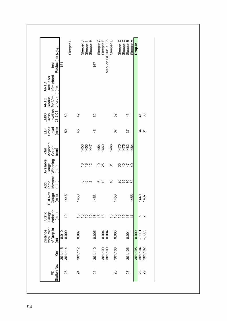
94
ED
I S
tatio
n N
o.K
m
Dis
tanc
e fr
om P
oint
of
Dro
p-in
(m
)
Sta
tic
Gau
ge
Var
iatio
n (m
m)
ED
I Net
t G
auge
(m
m)
Add
l. P
late
M
ovem
t (m
m)
Ava
ilabl
e G
auge
W
iden
ing
(mm
)
Tot
al
Adj
uste
d G
auge
(m
m)
ED
I C
ross
Le
vel
(mm
)
EM
80
Cro
ss
Leve
l on
28.2
.01
AR
TC
R
adiu
s fo
r 30
m
chor
d (m
)
AR
TC
R
adiu
s fo
r 10
m c
hord
(m
)In
st.
Rad
ius
(m)
Not
e30
1.11
50.
010
151
2330
1.11
40.
009
1014
4550
50S
leep
er L
2430
1.11
20.
007
1514
5045
4210
818
1453
Sle
eper
J10
818
1453
Sle
eper
I10
212
1447
Sle
eper
H25
301.
110
0.00
518
1453
4552
167
136
1914
54S
leep
er G
301.
109
0.00
413
1225
1460
Sle
eper
F30
1.10
90.
004
Mar
k on
GF
301
.108
615
1631
1466
Sle
eper
E26
301.
108
0.00
315
1450
3752
1520
3514
70S
leep
er D
1525
4014
75S
leep
er C
2730
1.10
60.
001
1730
4714
8237
46S
leep
er B
1714
5532
4914
84S
leep
er A
301.
105
0.00
0D
rop
-in
2830
1.10
4-0
.001
514
4034
4129
301.
102
-0.0
032
1437
3133

95
Location Diagram
301.1050km <= Point of Drop-in (Low Rail)
A DS Plate,1outer dogspike(new), 2 RLI
B Cast Plate, 2 Screwspikes (rebored),2 Pandrol E clips
C As on A, with loose raised lockspike on inside
D DS Plate, 2 loose lockspikes, 2 RLI
E As on B
301.1086km <= Mark on Gauge Face (Low Rail)
F /\ As on D, lockspikes raised
IG I As on A, with inner lockspike loose with broken leg
IH Direction As on B
ofI Travel DS Plate,2 RLI and 2 firm lockspikes
J As on I, lockspikes leaning outward,outer clip unsquare
K As on B loose screwspikes and holes leaning outward
L DS Plate,1 very loose inner lockspike only,2 RLI
Note: Leading wheel-set over high rail at 301.10225kmTrailing wheel-set at 301.0911km DS Plate = Double shouldered rolled steel plate
RLI = Rex-Lok-In = B296 Clip with Hook-in Adaptor
Description
APPENDIX 2
High Rail Fastenings

96
Loca
tion
AR
TC
30
mA
RT
C
10m
Inst
ant
10m
Str
ing-
line
Ado
pted
At F
ull
Fla
nge
Tot
al
Fla
nge
Wea
r1
Gau
ge
Wid
enin
g N
o1 W
heel
Gau
ge
Wid
enin
g N
o4 W
heel
Net
t G
auge
W
iden
ing
Tot
al
Cle
aran
ce
Sin
e A
ngle
of
Atta
ck-
Cho
rdal
2
Sin
e A
ngle
of
Atta
ck-
Jam
min
g
105
174
2022
4935
8412
60.
0093
940.
0559
3310
617
420
2247
2875
117
0.00
9394
0.05
2471
107
174
2022
4022
6210
40.
0093
940.
0474
7110
817
420
2231
1849
910.
0093
940.
0424
7110
914
717
420
2225
1641
830.
0093
940.
0393
9411
016
717
420
2219
1534
760.
0093
940.
0367
0211
117
420
2218
1230
720.
0093
940.
0351
6411
217
420
2215
823
650.
0093
940.
0324
7111
317
420
2215
520
620.
0093
940.
0313
1711
417
420
2210
818
600.
0093
940.
0305
4811
515
117
420
227
1623
650.
0093
940.
0324
7111
617
420
225
1520
620.
0093
940.
0313
1711
717
420
2210
717
590.
0093
940.
0301
6411
817
420
2220
525
670.
0093
940.
0332
4011
917
417
420
2212
1022
640.
0093
940.
0320
8712
017
417
417
420
223
1114
560.
0093
940.
0290
1012
118
020
227
1017
590.
0091
450.
0299
1512
218
120
2212
820
620.
0091
050.
0310
2812
318
220
2211
314
560.
0090
660.
0286
8112
418
520
2210
212
540.
0089
50.
0277
9612
518
720
226
39
510.
0088
750.
0265
6712
618
820
221
23
450.
0088
380.
0242
2312
718
920
222
24
460.
0088
010.
0245
7112
819
220
223
47
490.
0086
940.
0256
1712
919
419
420
222
46
480.
0086
240.
0251
6313
019
919
920
222
35
470.
0084
560.
0246
10
WO
DO
NG
A X
PT
DE
RA
ILM
EN
T 2
5.4.
01A
ng
le o
f A
ttac
k o
f D
erai
ling
Wh
eels
et
WO
DO
NG
A X
PT
DE
RA
ILM
EN
T 2
5.4.
01
A
PP
EN
DIX
3
Rad
ius
(m)
Tot
al R
ail C
lear
ance
(m
m)
Ang
le o
f Atta
ck
An
gle
of
Att
ack
of
Der
ailin
g W
hee
lset
Wod
onga
-Ang
le o
f Atta
ck.x
ls3/
21/0
2

97
R 1
74 m
R 1
99 m
R 1
74 m
R 1
99 m
0.00
9394
0.00
8456
0.05
5933
0.02
4610
00 32.2
9'00 29
.07'
30 12.3
8'10 24
.61'
Eff
ect
on
Lat
eral
Fo
rce
The
late
ral f
orce
at t
he le
adin
g w
heel
is d
irect
ly p
ropo
rtio
nal t
o th
e S
ine
<
1. In
crea
se d
ue to
sha
rpen
ing
of R
adiu
sC
hord
al11
.0%
(S
mal
l inc
reas
e)Ja
mm
ing
127%
(O
ver
21 / 4 ti
mes
)
2. In
crea
se d
ue to
rai
l cle
aran
ces
and
bogi
e tr
acki
ng (
jam
min
g)R
174
m49
5% (
Thi
s is
clo
se to
6 ti
mes
cho
rdal
)R
199
m19
1% (
Thi
s is
clo
se to
3 ti
mes
cho
rdal
)
Sin
e <
<
Rad
ius
Bo
gie
Tra
ckin
g
An
gle
of
Att
ack
Cho
rdal
Jam
min
g
An
gle
of
Att
ack
of
Der
ailin
g W
hee
lset

98

99
APPENDIX 2
Report prepared by Interfleet Technology Pty Ltd
1 . EXECUTIVE SUMMARY
This study considers the derailment of an XPT trailer car on a tight radius curve atWodonga on 25 April 2001.
The purpose of this report is to review the incident report documentation andphotographs as supplied by the ATSB, to carry out simple dynamics calculationsto look at the normal curving forces of an XPT trailer car, and to consider theeffects of any key issues arising from the document on the curving forces and thepropensity of derailment of the vehicle.
The report finds that although there were some faults on the vehicle, the primarycause of the derailment was the poor conditions of the fixings of the rails thatallowed lateral and roll motion of the rails under the passage of the train.

100
WODONGA XPT DERAILMENT INVESTIGATION ITPLR/TA341/01PAGE NO: 3
C ONTENTS PAGE NUMBER
WODONGA XPT D ERAILMENT INVESTIGATION .............................................1
1. EXECUTIVE SUMMARY ............................................................................4
2. INTRODUCTION ...................................................................................5
3. OBJECTIVES .........................................................................................5
4. ANALYSIS .............................................................................................6
4.1. Review of ATSB Documentation........................................................................................................................64.1.1. Vehicle Based Effects :-.....................................................................................................................64.1.2. Track Based Effects :-.........................................................................................................................74.1.3. Cause................................................................................................................................................................94.1.4. Investigation.............................................................................................................................................10
4.2. Bogie Rotational Resistance...............................................................................................................................11
4.3. Railway Vehicle Dynamics Calculations.................................................................................................124.3.1. Effect of X-Factor..................................................................................................................................124.3.2. Effect of Other Vehicles & Track Factors.......................................................................14
5. CONCLUSIONS ................................................................................. 17
5.1. Why did the passenger train derail and not the preceeding heavier freighttrain?......................................................................................................................................................................................................17
5.2. Why did just one bogie derail and then subsequent bogies pass safely over thederailment site?...........................................................................................................................................................................18
5.3. What was the primary cause of the derailment?...........................................................................19
6. RECOMMENDATIONS ......................................................................... 20
6.1. Track Maintenance Considerations............................................................................................................20
6.2. Vehicle Maintenance Conditions..................................................................................................................20
7. REFERENCES ...................................................................................... 21
FIGURES 1 - 5

101
WODONGA XPT DERAILMENT INVESTIGATION ITPLR/TA341/01PAGE NO: 5
2 . INTRODUCTION
On Wednesday 25 April 2001, a Countrylink Sydney-Melbourne XPT passengertrain derailed at Wodonga on 175m radius, right hand curve. The consist waspower car + 7 passenger cars + power car. The leading bogie of the fifthpassenger car derailed. Since the train travelled for about 1000m followingderailment, the last two passenger cars and the rear power car must have passedover the derailment site without derailing. The process of derailment, asindicated by site evidence, was that the inner wheel of the leading axle droppedinto the four-foot. Following this, the outer wheel climbed the outer rail. Installedcant at the derailment site was nominally 40mm. At the time of derailment, thetrain speed was aproximately 30 km/h, within the 40km/h line speed.
3 . OBJECTIVES
The objectives of the report are as follows:
1. To review the derailment incident report documentation [Ref. 7.1] suppliedby the Australian Transport Safety Bureau (ATSB).
2. To find measured bogie-rotational resistance data for the UK Mk3 coachwith BT10 bogies (very similar to XPT trailer car) and comment on the effectof increased bogie rotational resistance on derailment performance.
3. To carry out simple railway vehicle dynamics calculations to consider:
i) The normal curving forces generated by an XPT trailer vehicle on a175m radius curve with 40mm installed cant at 36km/h.
ii) The effects on the curving forces and propensity to derailment of anykey issues arising from the ATSB documentation.

102
WODONGA XPT DERAILMENT INVESTIGATION ITPLR/TA341/01PAGE NO: 6
4 . ANALYSIS
4.1. REVIEW OF ATSB DOCUMENTATION
The documentation supplied that was reviewed is listed in Ref. 7.1.
4.1.1. VEHICLE BASED EFFECTS : -
• Bogie rotational resistance
The photographs show considerable wear damage to the secondaryyaw friction surfaces on the derailed XPT trailer car bogie. However,wear damage such as this is not uncommon on UK BT10 bogies so isnot thought to be of great relevance. It seems most likely that the pinon the sidebearer became bent as a result of the derailment, and wasnot a cause. The photo of the sidebearer mounting surface does notindicate (as far as can be seen from the photo) any signs of frettingthat would be expected if the pin was damaged previously.
Also, in order to bend the pin as shown in the photographs, it wouldbe necessary to lift the pin partially out of its holder, and then apply alateral force. Normally, the weight of the vehicle body on the bolsterwould locate the pin in its holder. The weight of the vehicle on thebolster would be reduced, or possibly removed, during derailment. Ittherefore seems most likely that the damage to the pin occurredduring derailment.
Two test reports have been found for bogie rotational resistance forUK Mk3 coaches. One is for a Mk3 RF restaurant car and the other isfor a Mk3 sleeper car. Both show X-factor of about 0.05, well withinthe limit of 0.10. These vehicles are both heavy Mk 3 coach examplesbut of similar axleload to that given for the XPT trailer car (10.5t).However, these results show that the measured rotational resistancecan nearly double on a Mk3 coach and still be within acceptablelimits. This is discussed further in Section 6.2.
• Rolling Radius Difference
The rolling radius difference on the derailed wheelset was such thatWheel 1, the leading outer wheel that derailed, would be expected tobe subjected to a higher than usual lateral flange force.

103
WODONGA XPT DERAILMENT INVESTIGATION ITPLR/TA341/01PAGE NO: 7
• Thin flange:
The thin flange is likely to be a consequence of the rolling radiusdifference causing the wheelset to run off-centre, but is not likely tohave contributed to the derailment itself. However, the additionalflangeway clearance would result in :-
• A higher angle of attack, hence slightly increased flange force.• More significantly, the inner wheel would be closer to the edge of
the inner rail when the outer wheel is in flange contact.
• Flange-back spacing
The UK requirement for flange-back spacing is 1360 - 1362mm. TheAustralian requirement applies the tolerance the other way, i.e., it is1360 - 1358mm. The XPT wheelset that derailed had a flange-backspacing of 1357mm. This is equivalent to an additional 1-3mmflangeway clearance, as discussed above.
4.1.2. TRACK BASED EFFECTS : -
• Gauge Widening
There is a small amount of static gauge widening on the curve, but aconsiderable amount of dynamic gauge widening indicated by thesigns of movement of the base plates on the sleepers.
• Rail Roll
Weakness of the rail fasteners would allow rail roll that would furtherincrease the gauge.
• Track Twist
Some track twist is noted from the cant measurements that may becontributory to the derailment.

104
WODONGA XPT DERAILMENT INVESTIGATION ITPLR/TA341/01PAGE NO: 8
• Check Rail
It is noted that no check rail is present on this curve. Previously, UKpractice was to have check rails on all passenger running lines of200m radius or less, although currently it is simply arecommendation.
• Cant Excess/Deficiency
For 1435mm gauge track the expression for calculating cantdeficiency is:-
CD = 11.82 x V 2
- Ea R
Where CD = cant deficiency (mm)Ea = installed cant (mm)V = speed (km/h)R = curve radius (m)
Therefore, at the derailment site:
CD = 11.82 x 36 2
- 40175
= 48mm
This shows that the vehicle is at a speed above balancing speed, andis experiencing a small amount of cant deficiency.
Generally, vehicles are most at risk of derailment when travelling atslow speed on curved track with high installed cant. Under theseconditions, the vehicle weight is shifted towards the inner rail enablinga higher lateral force to be generated that is reacted at the leadingouter wheel. Hence, gauge-spreading force is high. In addition, sincethe vehicle weight is shifted away from the outer wheel, the L/V ratio ishigh so the risk of flange climbing is increased.
Under cant deficiency conditions, the leading outer wheel has agreater vertical load, reducing the risk of flange-climbing. The cantdeficiency force tends to be reacted by the trailing wheelset of thebogie moving towards the outer rail. This helps align the leadingwheelset reducing its angle of attack.

105
WODONGA XPT DERAILMENT INVESTIGATION ITPLR/TA341/01PAGE NO: 9
At very high levels of cant deficiency, there is a risk of overturning, butunder still wind conditions, this is well beyond the usual operatingregime.
Hence, at 48mm cant deficiency, the risk of derailment wouldnormally be low.
4.1.3. CAUSE
It is noted that the process of the derailment was that the inner wheeldropping into the four-foot, followed by the outer wheel climbing overthe outer rail.
Analysing this simply, based on wheelset dimensions:-
For new wheels on new rails:
Flange-back 1360mmWheel thickness 127mmFlange thickness 30mmTrack gauge 1435mm
If the outer wheel is in flange contact with the outer rail, the distancefrom the outer wheel flange face to inner wheel rim is:30+1360+127=1517mm.
Hence, overlap of inner wheel over inner rail is 1517-1435 = 82mm.
For UK track, we might expect about 6mm gauge-widening for a175m radius curve, maximum 18mm side-wear (for secondary routeonly) and 24mm minimum flange thickness.
Hence, minimum expected UK overlap of inner wheel over inner railis:-
(24+1360+127) – (1435+6+18) = 52mm
In practice, such a case would not normally occur since presence of acheck rail would maintain a greater overlap of the inner wheel.
For the case of the XPT derailment, we have:-
Flange-back 1357mmWheel thickness 127mmFlange thickness 18mmTrack gauge 1435+49 dynamic gauge = 1484mm
(page 19 of Report [Ref. 7.1], sleeper 12)

106
WODONGA XPT DERAILMENT INVESTIGATION ITPLR/TA341/01PAGE NO: 10
Hence, XPT overlap of inner wheel over inner rail is:
(18+1357+127) – (1484) = 18mm
This is clearly a small value of overlap. If we take into account theouter chamfer of the wheel that effectively reduces the wheel rim widthby a further 6mm, we have just 12mm of overlap remaining. Hence,there is a high risk of derailment caused by the inner wheel treaddropping into the four foot.
Further analysis is made on this, based on the measured wheel andrail profiles.
Figure 1 shows that the flange of the leading outer wheel (Wheel 1)fits well into the worn side of the outer rail. By taking account of the1357mm back-back dimension and 49mm dynamic gauge wideningthe position of the inner wheel on the inner rail may be predicted asshown in Figure 2. This demonstrates the narrow band of contact onthe inner rail with the wheel chamfer close to the gauge corner of therail. No allowance has been made in this illustration for outer rail rollwhich would reduce the inner rail contact further.
4.1.4. INVESTIGATION
It is notable that following derailment of the one bogie, the remainderof the train passed over the derailment site safely. This would indicatethat, whilst the track-based elements must be relevant, it is only thecombination of the vehicle-based and track-based elements togetherthat caused derailment.
Our dynamics calculations to investigate this are therefore basedaround the following plan:-
1. For 175mm constant radius curve, 40mm installed cant, 36km/htrain speed, what are lateral wheel-rail forces caused by:-• Bogie rotational resistance?• Rolling radius difference?• Gauge widening?• Flange-thickness and flange-back spacing?These are applied individually, then all together.
2. To repeat the above, but for track of 175mm constant radiuscurve, measured track cross level and measured track dynamicgauge.
These calculations are described in Section 4.3.

107
WODONGA XPT DERAILMENT INVESTIGATION ITPLR/TA341/01PAGE NO: 11
4.2. BOGIE ROTATIONAL RESISTANCE
A search was made for British Railways (BR) test reports for bogierotational resistance tests carried out on BR Mk3 coaches fitted with BT10bogies. The BR Mk3 coach with BT10 bogies was the basis for the XPTtrailer car. Although there are differences, the frictional interface thatcontrols bogie rotational resistance is similar on Mk3 and XPT, so theresults for Mk3 should be representative of XPT.
Although many rotational resistance tests must have been carried out forthe various Mk 3 coach types during their development and build, onlytwo test reports could be found. These were for:-
• Mk3 RFM Restaurant car [Ref. 7.2].• Mk3 Sleeper car [Ref. 7.3] - Note that this Sleeper car had various
suspension modifications for improved ride development, but noalterations were made that would change bogie rotational resistance.
The bogie rotational resistance is measured and the “X-factor” iscalculated according to the following formula:
X = Body-bogie yaw torque Wheelbase x Axle Load
The current UK requirement is that X ≤ 0.1 for passenger vehicles, parcelvehicles and locomotives (higher values of X are permitted for low (<8t)axleload freight vehicles). The value of X should not be exceeded for thebogie yaw angle required for the minimum curve radius and for rotationalspeeds representative of curve entry and exit in service conditions.
The Mk3 RFM vehicle gave X-factor results in the range 0.050 and 0.053(for an axleload of 9.8 Tons).
The Mk3 Sleeper gave X-factor results in the range 0.049 and 0.053 (foran axleload of 103 kN).
It is noted from the ATSB report that the XPT passenger car axleload isabout 10.5 tonnes, similar to the Mk3 coaches tested. Hence an X-factorvalue of about 0.05 would be expected for the XPT trailer car.
This value of X-factor is well inside the UK limit of 0.10 for passengervehicles. The effect of X-factor on derailment is discussed further in Section4.3.

108
WODONGA XPT DERAILMENT INVESTIGATION ITPLR/TA341/01PAGE NO: 12
4.3. RAILWAY VEHICLE DYNAMICS CALCULATIONS
Railway vehicle dynamics calculations were made using the program“Vampire”. A computer model of a UK Mk3 coach was used since, asdiscussed in Section 4.2, this is very similar to the XPT trailer car. The onlychange made was to increase the body mass of the UK vehicle to give a10.5t axle load as per XPT. A check was made that the modeldemonstrated an X-factor of 0.05, as measured by test on actual Mk3coaches (see Section 4.2).
A piece of track was set up in Vampire of 175m radius, 40mm installedcant, and the vehicle model was run around this curve at 36km/h. Thewheel and rail profiles used for the purposes of the calculations was a UKP8 wheel profile and 113A rail inclined at 1:20 at 1435mm gauge.Wheel-rail friction coefficient was set at an average value of 0.23.
4.3.1. EFFECT OF X-FACTOR
The “base case” run was for an X-factor of 0.05. Further runswere then made for X-factor values of 0 (i.e., freely-pivoting) and0.20 (i.e., 4 x the measured X-factor value).
The resulting leading wheelset forces for these cases are:-
Case Ldg.Outer WheelLateral Force *
Ldg.Inner WheelLateral Force *
Gauge SpreadingForce
L/V Ratio
1. X=0.00 27.1 kN 15.1 kN 42.2 kN 0.442. X=0.05 30.5 kN 14.6 kN 45.1 kN 0.483. X=0.20 40.6 kN 13.2 kN 53.8 kN 0.61
* Positive force indicates lateral force is pushing rail outwards
The L/V ratio is a measure of the likelihood of a flange-climbingderailment and is the ratio of the vertical load on the leadingouter wheel divided by the lateral force. For safety, the L/V ratioshould be less than 1.20.
These results show that the differences in wheel-rail lateral forcebetween a freely-pivoting bogie case and a bogie with an X-factor of 0.05 are small (leading outer wheel-rail force increasesfrom 27.1 to 30.5 kN). Increasing X-factor further to a value of0.20 increases the leading outer wheel-rail force to 40.6 kN.Hence, the increase in this force is a linear increase over this X-factor range of about 3.4 kN per 0.05 increase in X-factor. Inall cases, L/V is well inside the 1.20 limit.

109
WODONGA XPT DERAILMENT INVESTIGATION ITPLR/TA341/01PAGE NO: 13
Let us consider the body-bogie yaw friction coefficient, µ, for thisvehicle at 10.5 tonne axle load :-
Re-arranging the X-factor equation gives us :
Body-bogie yaw torque = X x Wheelbase x Axle Load
For X=0.05 :Body-bogie yaw torque = 0.05 x 2.60 x 10.5 x 9.81
= 13.4 kNm/bogie
Bogie mass (approx.) = 5.5 tonnesPivot load = [(4 x 10.5) – (2 x 5.5)] x 9.81 = 152 kN
2
Body-bogie yaw torque is due to pivot load on friction pads.
Yaw torque = Pivot load x µ x friction pad semi-spacing
Friction pad semi-spacing = 0.725m
Hence, for X=0.05 :
Yaw torque = 13.4 = 152 x µ x 0.725
Friction pad friction coefficient, µ = 13.4 = 0.12152 x 0.725
For the derailed vehicle where metal-metal contact was found,the friction coefficient would be higher. Ref. 7.4 gives values offriction coefficient for dry metal-on-metal of 0.15-0.60 static and0.1-0.5 sliding. Hence, an average value of sliding friction of0.3 would represent an X-factor of about 0.13, and themaximum value of sliding friction of 0.5 would represent an X-factor of about 0.20.
Hence, an X-factor applicable to the derailed bogie wouldappear to be in the range 0.13 – 0.20.

110
WODONGA XPT DERAILMENT INVESTIGATION ITPLR/TA341/01PAGE NO: 14
4.3.2. EFFECT OF OTHER VEHICLES & TRACK FACTORS
Further calculations were made to look at the effects of thefollowing factors noted in the ATSB report:-
• Rolling radius difference (2mm)• Thin flange (18mm)• Reduced wheelset back-back distance (1357mm)• Wide track gauge (max. +17mm static, +49mm dynamic)
These effects were applied first individually, then all together tothe base model. However, none of these showed any greateffect :-
• The rolling radius difference of 2mm on the leading wheelsetof the bogie in the Vampire model causes that wheelset toroll with a mean lateral offset on straight track sufficient forthe leading outer wheel to be contacting the rail in the flangeroot area of the wheel profile, close to flange contact.However, once in flange contact on a 175m radius curve, thechange in lateral wheel-rail force, compared to that of wheelsof equal radius, is minimal.
• The effect of the reduced wheelset back-back distance andthe thin flange had little effect on forces. Once combined withthe gauge widening, the lateral forces actually reduced. Thereason for this is thought to be that at such excessive gaugewidening the contact point on the inner wheel tread is on theoutermost 1:10 coned portion of the tread. This increases therolling radius difference between the inner and outer wheelssuch that the lateral forces are reduced.
Combining all these effects together as constant input valuesthroughout the curve has little effect on the results, such that thewheel-rail force at the leading outer wheel remains at about30kN, the inner wheel-rail force is about 15kN and the gauge-spreading force is about 45kN (as per X-factor results in Section4.3.1).
If the measured dynamic gauge and cross-level inputs aresuperimposed as an irregularity on the curve, the resultingdynamic lateral forces are increased. A peak gauge-spreadingforce of 70kN is seen, with a force of about 65kN sustained for2m. This is made up from an outer rail force of about 41kN andan inner rail force of 24kN, both sustained for 2m.

111
WODONGA XPT DERAILMENT INVESTIGATION ITPLR/TA341/01PAGE NO: 15
This increase is greater than if a random irregularity issuperimposed on to the smooth curve, indicating that the shapeof the measured input is an important factor to the higher forcelevels predicted. Figures 3 & 4 illustrate the gauge variationinput and leading outer wheel lateral force output, showing thesimilarity of the shape of the input and output data.
The measured dynamic gauge [Ref. 7.1] shows a rapid increasein gauge approaching the derailment site, followed by a rapiddecrease in static gauge. The dynamic gauge increases from+12mm at sleeper 5 to +47mm at sleeper 11. Assuming anaverage sleeper spacing of 700mm, this equates to a dynamicgauge change of just over 8mm/m. This is followed by a rapiddecrease in gauge of around 9mm/m from sleepers 14 to 18.This is equivalent to a 17mrad kink superimposed on to the175m radius curve, giving rise to the dynamic increase in lateralwheel-rail force close to the point of derailment.
In order to consider the likely force levels that would have beenexerted on the track by the preceding freight trains over thisderailment site, a further run was made for the Mk3 coach, butwith axle load increased to 200 kN. This approximates to a 20taxle load bogie freight vehicle. The leading outer wheel forceincreases from the 30 kN of the 10.5t axle load passengervehicle to about 50kN for the 20t axle load freight vehicle.
These lateral forces were all predicted for a wheel-rail frictioncoefficient of 0.23, which is considered to be an avaerage valuefor rolling wheel-rail friction in the UK. A higher frictioncoefficient may be appropriate for this derailment. The effect ofa higher friction coefficient would be to increase the lateral forcevalues.
The effect of a large lateral force at the outer rail would be to tryand push the rail outwards. The lateral force is applied at therail head. The rail is restrained from lateral and roll movementsby the fasteners at the foot of the rail. If the fasteners are loosein the sleepers, the rail will slide sideways until the slack in thefasteners is taken up, and will then try to roll the rail outwardsabout a point at the outside of the rail foot.
The effect of the vertical wheel load is to apply a moment to therail that opposes the moment of the lateral force attemting to railthe rail outwards.

112
WODONGA XPT DERAILMENT INVESTIGATION ITPLR/TA341/01PAGE NO: 16
Therefore, the rail will not begin to roll outwards until the torquefrom the lateral force equals that of the vertical force. After thispoint the rail is restrained by the torsional stiffness of the railitself, probably over a length of 2.6m to the trailing wheelset,where there is a restraining vertical force and a lesser lateralforce. (Structural calculations could be made to estimate the raildisplacements under such forces).
Figure 5 shows the vertical and lateral wheel forces acting on theouter rail. This diagram shows that for an axle load of 10.5 t(51.5 kN wheel load), if there is no restraint from the railfasteners to react the rail roll, then the rail will have a tendencyto roll out for any lateral wheel-rail force that exceeds about 27kN. The calculations show that the lateral wheel-rail force ispredicted to be 30 kN for X=0.05 on a smooth curve. Figure 2(with no rail roll) shows that there is little overlap of the innerwheel over the inner rail. Hence, very little rail roll is required forthe inner wheel to drop off the inner rail and into the four foot.
For a heavier axle load vehicle the lateral force at the outer railis increased, but not by the same proportion as the increase inrestraining vertical wheel load. Figure 5 shows that a lateralforce is in excess of 53 kN is required to roll the rail outwardswith a 20 t axle load. The calculations for a 20 t axle loadvehicle predicts a force of 50 kN at the outer rail for a smoothcurve, but the track irregularities would produce dynamic forcesin excess of this. Therefore, although a heavier freight vehicleproduces higher lateral forces, the restraining axle load is alsohigher. As a result, the heavier freight vehicle does not have anincreased derailment risk, over a lighter passenger vehicle, asmay have been perceived.

113
WODONGA XPT DERAILMENT INVESTIGATION ITPLR/TA341/01PAGE NO: 17
5 . CONCLUSIONS
In order to conclude this study, there are three questions that arise from thisderailment :-
1. Why did this passenger train derail and not the preceding heavier freighttrain?
2. Why did just one bogie derail and then subsequent bogies pass safely overthe derailment site?
3. What was the primary cause of the derailment?
It has not been possible to fully answer all these questions within the scope andavailable information for the report, but they are discussed below:-
5.1. WHY DID THE PASSENGER TRAIN DERAIL AND NOT THE PRECEEDING HEAVIER
FREIGHT TRAIN?
At first sight, it may be expected that the preceding freight train may havebeen at greater risk of derailing on this curve than the passenger train,since it imposes greater forces on the track. However, this overlooks thefact that the greater axle load of the freight train actually helps to restrainthe track.
With loose track fastenings, the only restraint from initiating rail movementcomes from the weight of the train acting vertically on the rails. Initially, therail and its baseplates will slide sideways on the sleeper. The onlyresistance to this will be the resisting frictional resistance between the railbaseplate and the sleeper. Once the lateral freedom is taken up, there willbe a tendency for the rail to roll outwards. Resisting this will be therestoring moment from the vertical load of the train on the rails. Once themoment from the vertical load is overcome, the torsional stiffness of the railwill resist rail roll.
Due to the tight curve radius of 175m, the static lateral wheel-rail curvingforces will be high. Increasing the axle load of the vehicle will give aproportional increase in the resistance to rail lateral and roll movement.However, the increase in lateral force is smaller than the proportionalincrease in vertical load, so there is less tendency for rail to begin roll outwith a heavier axle load.
The calculations made show the margins to be relatively small, such that thederailment risk of the freight train was only slightly better than that of thepassenger train. However, this is a contributory factor to the passengertrain derailing when the preceding freight train did not.

114
WODONGA XPT DERAILMENT INVESTIGATION ITPLR/TA341/01PAGE NO: 18
5.2. WHY DID JUST ONE BOGIE DERAIL AND THEN SUBSEQUENT BOGIES PASS
SAFELY OVER THE DERAILMENT SITE?
It is this fact that leads to the conclusion that the condition of the track wasthe primary cause of derailment.
Usually, in a derailment that begins by the inner wheel dropping off theinner rail into the four foot, the wheelset would be expected to become“jammed” with the outer rim face of the inner wheel against the gauge faceof the inner rail and the outer wheel remaining on the outer rail, forcedhard into flange contact. Further forward motion of the train will causemany track fixings to be broken as the derailed wheelset forces the railsapart.
In this case, the rails were sufficiently flexible that once the inner wheel hadderailed, the outer rail rolled out until the outer wheel climbed over the rail(with the leading wheelset of the bogie derailed, the trailing wheelset has noguidance and would be expected to derail in the same manner). What issurprising is that once derailed, the rails appear to have sprung back into aposition close to their original position, such that the rest of the train passedsafely over the site.
If the track at this site had been as strong as should be expected prior to thederailment, and the derailment had been due to the passenger trainexerting excessive forces on the track, it would have been expected thatbroken track fastenings would have been found due to the process ofderailment. The rails would be expected to remain in a displaced position,leading to the likelihood of further wheelsets being derailed.
The fact that the rails were able to move outwards until derailment occurredand then spring back into position is illustration of just how poorly the railswere fixed.

115
WODONGA XPT DERAILMENT INVESTIGATION ITPLR/TA341/01PAGE NO: 19
5.3. WHAT WAS THE PRIMARY CAUSE OF THE DERAILMENT?
The faults on the XPT trailer car such as the differing wheel diameters (2mmdifference in diameter on the leading wheelset), the over-thin flange (1mmbelow minimum flange thickness on wheel 1) and the reduced flange back-back dimension (1mm too narrow at 1357mm on wheelset 1) should nothave been present. However, according to the “Vampire” predictions thesehad little influence on the wheel forces generated at the derailment site.They had an influence on reducing the amount of tread remaining in contacton the inner rail of this curve, but their contribution was small compared tothe wide dynamic gauge of the track.
The secondary yaw friction pads had worn into poor condition and this islikely to have led to an increase in bogie rotational resistance of the bogie.However, the order of increase in the leading outer wheel-rail force would beexpected to be just 3–10 kN due to the increase in rotational resistance, andthe lateral force level would be less than that of a 20t axle load freight train.
For a tight curve radius of 175m radius, high static lateral curving forcesshould be expected. Therefore, it is essential that the rails are securelylocated in position. This is even more important on such a tight curve withno check rail. The presence of a check rail, correctly installed, would sharethe lateral forces between the outer rail and the check rail. In addition, thecheck rail would restrain the inner wheel flange back to keep the inner wheeltread on top of the inner rail. It is clear from the description andphotographs of the track that the rails were not secure. The fixings wereloose, or even missing, and there was clear evidence of the baseplatessliding sideways on the sleepers. These faults should have been noted oninspection. A preventative measure that could have been put in place beforemajor repair would have been to fix tie-bars across the rails in order to retainthe static gauge. These prevent lateral movement of the rails, but offer noadditional restraint to rail roll since they are located at the foot of the rail.However, there is no note of even this simple preventative measure.
Based on the evidence supplied, the primary cause of the derailment is seento be the poor condition of the rail fastenings. The rails were not securedsufficiently to maintain the rails at a constant gauge and in an uprightposition under the passage of trains.
The condition of the yaw friction pads of the train is not seen as acontributory cause to the occurrence of this derailment since the predictedlevel of increase in lateral wheel-rail force is small, and still less than that ofa heavier axle load train. The condition of the yaw friction pads may wellhave been a contributory cause as to why this XPT trailer car derailed, andnot a later train. However, it is clear from the dynamic gauge of the trackthat any train passing over this site was very close to the point of derailing.

116
WODONGA XPT DERAILMENT INVESTIGATION ITPLR/TA341/01PAGE NO: 20
6 . RECOMMENDATIONS
The recommendations arise from this derailment are a series of actions to ensurethat maintenance practices in place are sufficient to prevent a recurrence of suchan event :-
6.1. TRACK MAINTENANCE CONSIDERATIONS
Consideration needs to be given to track maintenance :-
A. Inspections for :-• defective/cracked/broken baseplates/pandrol housings/chairs;• missing, defective or not secure chair screws/spikes/bushes;• missing, defective or not secure clips/keys;• poor sleeper condition, cracked, broken, rotten, providing
inadequate vertical or lateral restraints to baseplate or rail.
B. Rectification action trigger if number of defects exceed interventionlevel over fixed length of track or if number of consecutive defectsalong track exceed another intervention level.
C . Could have layered rectification action responses, with urgentactions needed to mitigate serious safety risk and less stringentactions for track conditions with less rail fastening defects.
D. Audit to check process is working.
6.2. VEHICLE MAINTENANCE CONDITIONS
Consideration also needs to be given to vehicle maintenance :-
1. A review of the compatibility of the wheel-rail interface geometryincluding maximum track gauge, allowable rail side wear, minimumflange thickness and flange back-back spacing.
2. A review of the wheelset inspection and maintenance procedures inplace for XPT trailer cars.
3. A review of the bogie overhaul procedures and intervals for XPTtrailer cars with particular reference to the condition of the yawfriction pads on vehicles that arrive for overhaul.
Interfleet could give guidance on such systems.

117
WODONGA XPT DERAILMENT INVESTIGATION ITPLR/TA341/01PAGE NO: 21
7 . REFERENCES
7.1 Documentation provided by ATSB to Interfleet Technology Pty on 13.6.01that included:-• CountryLink “Analysis of Hasler Speed Recording Tape Report” dated
4 May 2001, 4 pages.• “Wheel Profiles taken at Railfleet Services, Chullora on 24.5.2001, 4
pages.• Incident report “Derailment XPT Car XF2214, Wodonga, 25 April
2001, 11 pages.
Also the following photographs sent by email:-• Bogie.jpg• Bogie2.jpg• Carriage plate1.jpg• Carriage underside.jpg• Track and pin.jpg• Track fastenings.jpg• Track overhead.jpg
In addition, some clear measured wheel and rail profiles were supplied byfax.
7.2 B.R. Testing & Workshops Section Report no. 888, “R.F.M. AcceptanceTests, Bogie Rotational Resistance Test”, 11 April 1985.
7.3 B.R. Testing section Report no. 1276, “Mk3 Sleeper Coach Improved BT10Bogie, Static Tests”, 31 October 1991.
7.4 Kempe’s Engineers Year Book.

118
WODONGA XPT DERAILMENT INVESTIGATION ITPLR/TA341/01PAGE NO: 22
FIGURE 1
WHEEL- RAIL CONTACT AT LEADING OUTER WHEEL
FROM MEASURED WHEEL & RAIL PROFILES

119
WODONGA XPT DERAILMENT INVESTIGATION ITPLR/TA341/01PAGE NO: 23
FIGURE 2
WHEEL- RAIL CONTACT AT LEADING INNER WHEEL
FROM MEASURED WHEEL & RAIL PROFILES
& MEASURED DYNAMIC TRACK GAUGE

120
WODONGA XPT DERAILMENT INVESTIGATION ITPLR/TA341/01PAGE NO: 24
FIGURE 3
MEASURED DYNAMIC GAUGE IRREGULARITY INPUT TO VEHICLE

121
WODONGA XPT DERAILMENT INVESTIGATION ITPLR/TA341/01PAGE NO: 25
FIGURE 4
PREDICTED LATERAL FORCE OUTPUT AT LEADING OUTER WHEEL
FOR CALCULATION INCLUDING
MEASURED DYNAMIC GAUGE IRREGULARITY INPUT TO VEHICLE
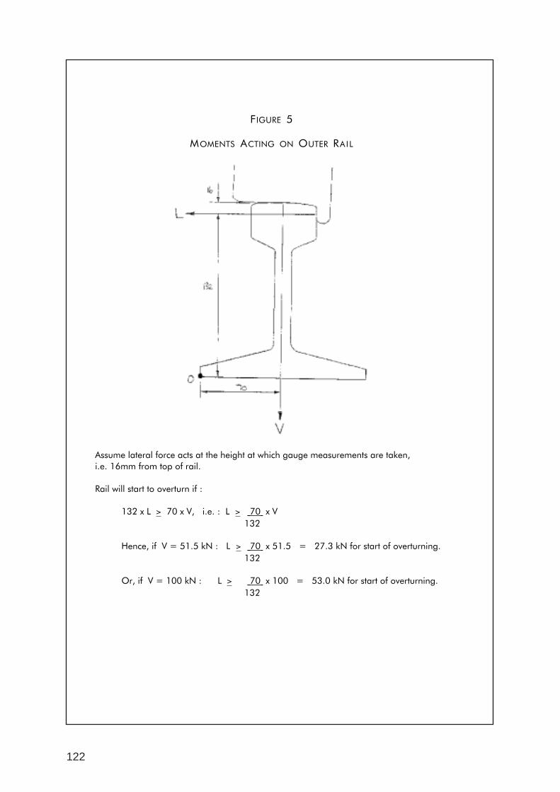
122
WODONGA XPT DERAILMENT INVESTIGATION ITPLR/TA341/01PAGE NO: 26
FIGURE 5
MOMENTS ACTING ON OUTER RAIL
Assume lateral force acts at the height at which gauge measurements are taken,i.e. 16mm from top of rail.
Rail will start to overturn if :
132 x L > 70 x V, i.e. : L > 70 x V132
Hence, if V = 51.5 kN : L > 70 x 51.5 = 27.3 kN for start of overturning.132
Or, if V = 100 kN : L > 70 x 100 = 53.0 kN for start of overturning.132
ww
w.a
tsb.
gov.
au18
00 6
21 3
72
AT
SB
Derailm
ent o
f passen
ger train
8622,Syd
ney – M
elbo
urn
e daylig
ht X
PT
service
ISB
N 0 642 20047 5