rahmat-samii - diffraction analysis of frequency selective reflector antennas
DESCRIPTION
Rahmat-Samii - Diffraction Analysis of Frequency Selective Reflector AntennasTRANSCRIPT
476 IEEE TRANSACTIONS ON ANTENNAS AND PROPAGATION, VOL. 41, NO. 4, APRIL 1993
Diffraction Analysis of Frequency Selective Reflector Antennas
Y. Rahmat-Samii, Fellow, IEEE, and A. N. Tulintseff, Member, IEEE
Abstract-Frequency selective surface (FSS) reflector antennas are used in many dual-reflector antenna systems in order to provide multifrequency capabilities. In the past, the diffraction analysis of reflectors was based primarily on the assumption of a solid subreflector configuration and only the gain loss caused by the presence of the FSS subreflector was accounted for. In this paper, a unified computational technique is presented which allows the incorporatiod of the curved FSS geometry in the computation of the antenna radiation pattern. The scattered fields from an illuminated FSS reflector are formalized using Huygens’ principle in such a way that the “reflecting” and the “transparent” FSS subreflector cases are treated identically and the thickness of the FSS subreflector remains arbitrary. The analysis utilizes local surface coordinates to describe the reflectiodtransmission matrices of the FSS subreflector where it is assumed that these matrices are available. In most cases one may use the local tangent plane for approximating the plane of the FSS in the local coordinate surface of the reflector. The paper demonstrates how the local curved coordinate system can be introduced in the diffraction modeling of FSS reflectors and its importance in accurately predicting the side-lobe and cross- polarization levels. Results of numerical simulations are presented for several FSS subreflector configurations.
I. INTRODUCTION HERE are many examples where frequency selective T surface (FSS) subreflectors are utilized in dual-reflector
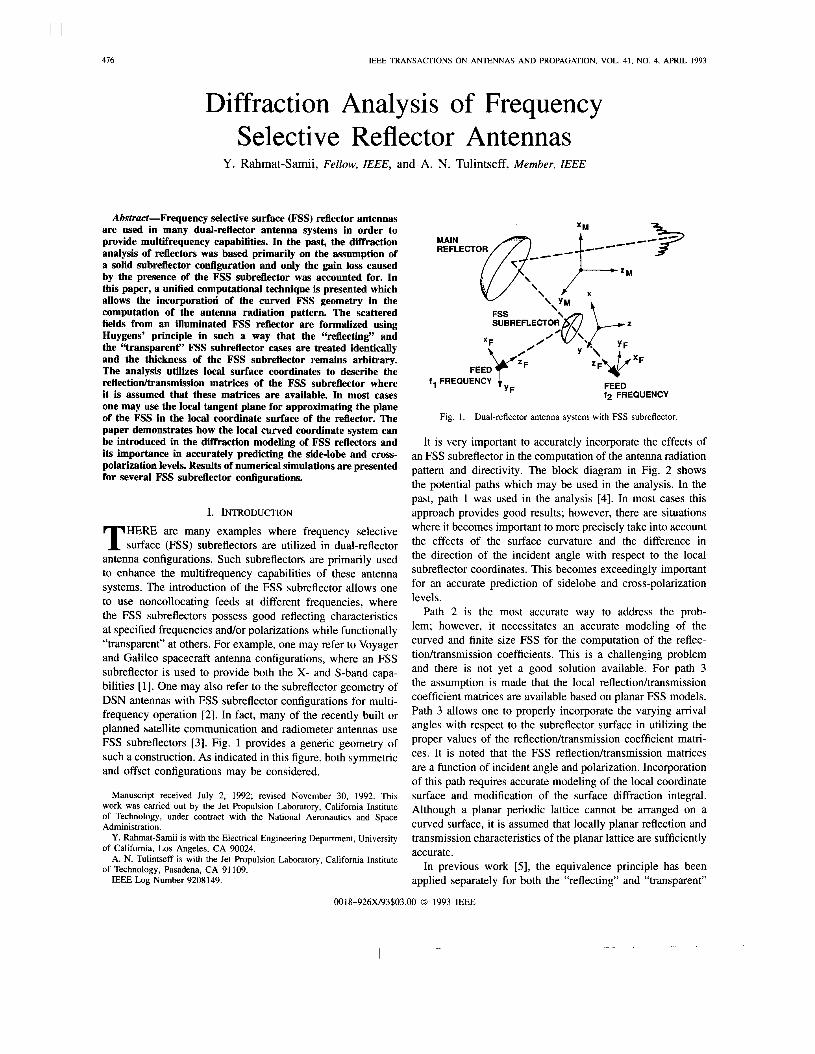
antenna configurations. Such subreflectors are primarily used to enhance the multifrequency capabilities of these antenna systems. The introduction of the FSS subreflector allows one to use noncollocating feeds at different frequencies, where the FSS subreflectors possess good reflecting characteristics at specified frequencies andor polarizations while functionally “transparent” at others. For example, one may refer to Voyager and Galileo spacecraft antenna configurations, where an FSS subreflector is used to provide both the X- and S-band capa- bilities [ 11. One may also refer to the subreflector geometry of DSN antennas with FSS subreflector configurations for multi- frequency operation [2]. In fact, many of the recently built or planned satellite communication and radiometer antennas use FSS subreflectors [3]. Fig. 1 provides a generic geometry of such a construction. As indicated in this figure, both symmetric and offset configurations may be considered.
Manuscript received July 2, 1992; revised November 30, 1992. This work was carried out by the Jet Propulsion Laboratory, Califomia Institute of Technology, under contract with the National Aeronautics and Space Administration.
SUBREFLECTOR FSS
‘1
Fig. 1. Dual-reflector antenna system with FSS subreflector.
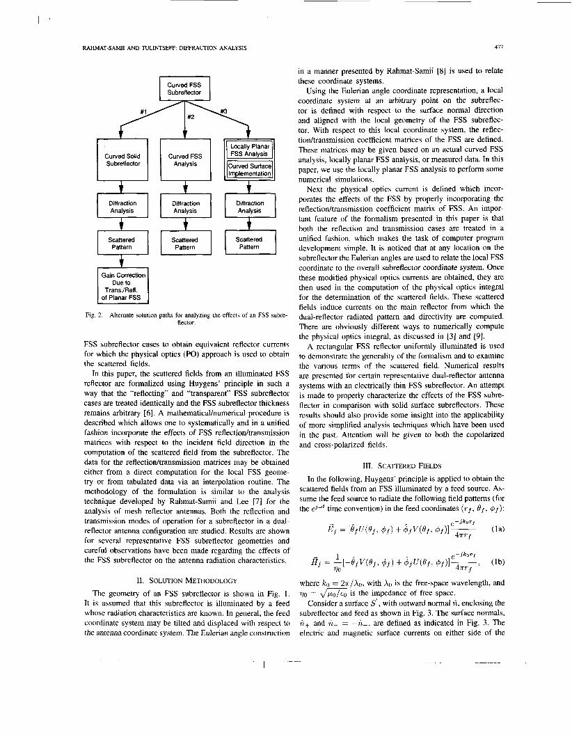
It is very important to accurately incorporate the effects of an FSS subreflector in the computation of the antenna radiation pattern and directivity. The block diagram in Fig. 2 shows the potential paths which may be used in the analysis. In the past, path 1 was used in the analysis [4]. In most cases this approach provides good results; however, there are situations where it becomes important to more precisely take into account the effects of the surface curvature and the difference in the direction of the incident angle with respect to the local subreflector coordinates. This becomes exceedingly important for an accurate prediction of sidelobe and cross-polarization levels.
Path 2 is the most accurate way to address the prob- lem; however, it necessitates an accurate modeling of the curved and finite size FSS for the computation of the reflec- tiodtransmission coefficients. This is a challenging problem and there is not yet a good solution available. For path 3 the assumption is made that the local reflectiodtransmission coefficient matrices are available based on planar FSS models. Path 3 allows one to properly incorporate the varying arrival angles with respect to the subreflector surface in utilizing the proper values of the reflectiodtransmission coefficient matri- ces. It is noted that the FSS reflectiodtransmission matrices are a function of incident angle and polarization. Incorporation of this path requires accurate modeling of the local coordinate surface and modification of the surface diffraction integral. Although a planar periodic lattice cannot be arranged on a curved surface, it is assumed that locally planar reflection and
Y. Rahmat-Samii is with the Electrical Engineering Department, Universitv transmission characteristics of the Dlanar lattice are SUffiCienth - . accurate. of California, Los Angeles, CA 90024.
of Technology, Pasadena, CA 91 109. A. N. Tulintseff is with the Jet Propulsion Laboratory, Califomia Institute
In previous work [5], the equivalence principle has been IEEE Log-Number 9208149. applied separately for both the “reflecting” and “transparent”
0018-926)(/93$03.00 0 1993 IEEE
RAHMAT-SAM11 AND TULINTSEFF: DIFFRACTION ANALYSIS
1 CurvedFSS I Subreflector
Curved Solid Su breflector
Curved FSS Analysis
Diffraction U Analysis
Scattered Pattern
Due to TransJRefl.
of Planar FSS
Diffraction
Scattered I Pattern
FSS Analysis
Diff raction Analysis
I 1
Scattered Pattern
Fig. 2. Altemate solution paths for analyzing the effects of an FSS subre- flector.
FSS subreflector cases to obtain equivalent reflector currents for which the physical optics (PO) approach is used to obtain the scattered fields.
In this paper, the scattered fields from an illuminated FSS reflector are formalized using Huygens’ principle in such a way that the “reflecting” and “transparent” FSS subreflector cases are treated identically and the FSS subreflector thickness remains arbitrary [6] . A mathematicalhumerica1 procedure is described which allows one to systematically and in a unified fashion incorporate the effects of FSS reflectiodtransmission matrices with respect to the incident field direction in the computation of the scattered field from the subreflector. The data for the reflectiodtransmission matrices may be obtained either from a direct computation for the local FSS geome- try or from tabulated data via an interpolation routine. The methodology of the formulation is similar to the analysis technique developed by Rahmat-Samii and Lee [7] for the analysis of mesh reflector antennas. Both the reflection and transmission modes of operation for a subreflector in a dual- reflector antenna configuration are studied. Results are shown for several representative FSS subreflector geometries and careful observations have been made regarding the effects of the FSS subreflector on the antenna radiation characteristics.
11. SOLUTION METHODOLOGY
The geometry of an FSS subreflector is shown in Fig. 1. It is assumed that this subreflector is illuminated by a feed whose radiation characteristics are known. In general, the feed coordinate system may be tilted and displaced with respect to the antenna coordinate system. The Eulerian angle construction
in a manner presented by these coordinate systems.
411
Rahmat-Samii [8] is used to relate
Using the Eulerian angle coordinate representation, a local coordinate system at an arbitrary point on the subreflec- tor is defined with respect to the surface normal direction and aligned with the local geometry of the FSS subreflec- tor. With respect to this local coordinate system, the reflec- tiodtransmission coefficient matrices of the FSS are defined. These matrices may be given based on an actual curved FSS analysis, locally planar FSS analysis, or measured data. In this paper, we use the locally planar FSS analysis to perform some numerical simulations.
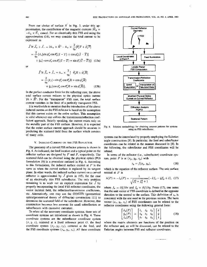
Next the physical optics current is defined which incor- porates the effects of the FSS by properly incorporating the reflectiodtransmission coefficient matrix of FSS. An impor- tant feature of the formalism presented in this paper is that both the reflection and transmission cases are treated in a unified fashion, which makes the task of computer program development simple. It is noticed that at any location on the subreflector the Eulerian angles are used to relate the local FSS coordinate to the overall subreflector coordinate system. Once these modified physical optics currents are obtained, they are then used in the computation of the physical optics integral for the determination of the scattered fields. These scattered fields induce currents on the main reflector from which the dual-reflector radiated pattern and directivity are computed. There are obviously different ways to numerically compute the physical optics integral, as discussed in [3] and [9].
A rectangular FSS reflector uniformly illuminated is used to demonstrate the generality of the formalism and to examine the various terms of the scattered field. Numerical results are presented for certain representative dual-reflector antenna systems with an electrically thin FSS subreflector. An attempt is made to properly characterize the effects of the FSS subre- flector in comparison with solid surface subreflectors. These results should also provide some insight into the applicability of more simplified analysis techniques which have been used in the past. Attention will be given to both the copolarized and cross-polarized fields.
111. SCATTERED FIELDS
In the following, Huygens’ principle is applied to obtain the scattered fields from an FSS illuminated by a feed source. As- sume the feed source to radiate the following field patterns (for the ejwt time convention) in the feed coordinates ( r f , O f , 4.f):
where IC0 = Z.lr/Xo, with A0 is the free-space wavelength, and 7/O = && is the impedance of free space.
Consider a surface S’, with outward normal h, enclosing the subreflector and feed as shown in Fig. 3. The surface normals, n+ and n- = -n+, are defined as indicated in Fig. 3. The electric and magnetic surface currents on either side of the

478 IEEE TRANSACTIONS ON ANTENNAS AND PROPAGATION, VOL. 41, NO. 4, APRIL 1993
LFSS SUBREFLECTOR
Fig. 3. FSS subreflector, feed, and enclosing surface S' .
FSS are defin5d as f+ = h* x I?* and G* = -h* x &, respectively. E, and H, are the aperture electric and magnetic fields of the feed.
Accounting for all contributions of q e tangential compq- nents of the electric and magnetic fields over the surface S , we obtain the following scattered fields [lo]:
Escat(3 = J S,,, dSf { - j w P o G ( ~ 1 .')[f+ + f-1
1 - v x G ( T l a') . [G+ + 2-1
+ 1 lee, dS'{ - jupoG(F, f ) . [h x I?a]
+ v x G(F, +) . [ii x Ea]
1 + v x G ( F l +) . [J; + 5 1
+ v x G ( F l f ) . [ii x I?(&] } (2b)
where G ( F l r') is the dyadic Green's function for isotropic free space. (Implicit in (2) is thJt f+ y d G+ exist on the front surface of the FSS, while J- and M- exist on the back surface of the FSS.) Using far-field approximations, the above equations become
for Locally Planar FSS
Curved FSS (concave, convex, or planar)
Fig. 4. Local tangent plane on curved FSS subreflector.
- i x i x SJ,, d ~ ' [ $ + + $-],Jkoi..g
where we have assumed that the feed aperture fields give rise to the radiated fields of the feed, i.e., the fields described in (1). For the reflecting FSS case, the fields arising from the feed aperture may be ignored if there is little back radiation from the feed in the scattered field (main reflector) direction. For the transmission, or nearly "transparent," FSS case, the scattered field is represented as a modification to the illuminating field and only integration over the FSS subreflecer surfaze is required. Obtaining the induced FSS currents J k and M* is discussed in the following sections.
Finally, the radiation fields from the main reflector, assumed to be perfectly conducting, +are obtained by integrating the physical optics current 2h x Hscat on the main reflector surface [31, [91.
Iv. INDUCED CURRENTS ON A LOCALLY PLANAR FSS
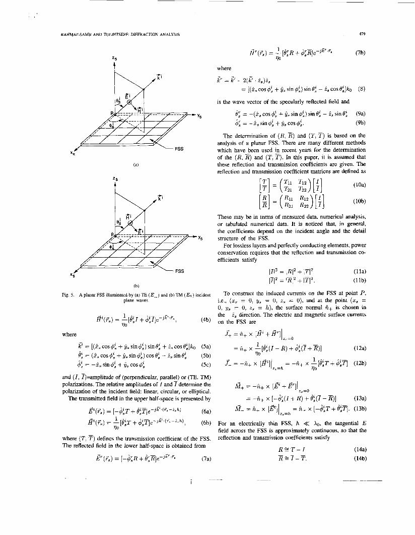
In this section, the induced current on the FSS surface is constructed. In computing the induced current at a specified point on the curved reflector surface, one makes the assump- tion that the surface is approximated by its tangent plane and then obtains the induced current on this plane as shown in Fig. 4. The tangent plane is depicted in Fig. 5 as an infinitely large planar FSS of thickness h with periodic cells in the FSS rectangular coordinate systems ( x S l y,, 2,). It is seen that ( zSl ys) are parallel to the sides of a unit cell, and z, is normal to the planar FSS pointing away from the incident field.
The FSS is illuminated by an incident plane wave given by, for 2, < 0.
@(FS) = [-@SI + &3+% (4a)
RAHMAT-SAM11 AND TULINTSEFF: DIFFRACTION ANALYSIS
=S
t
- ys
=S
4
(b)
Fig. 5. A planar FSS illuminated by (a) TE ( E l ) and (b) TM (Ell ) incident plane waves.
1
TO = - [ ~ z I + $:T]~-J ' 'SI (4b)
where
,P = [(is cos 4: + G~ sin 4:) sin 0; + i, cos O Z , ] I C ~ (5a) 0; = (2 , cos 4: + y8 sin 4:) cos 0: - is sin 0: (5b)
4: = -9, sin 4: + 6, cos 4; (5c)
and ( I , I)=amplitude of (perpendicular, parallel) or (TE, TM) polarizations. The relative amplitudes of I and f determine the polarization of the incident field: linear, circular, or elliptical.
The transmitted field in the upper half-space is presented by
( 6 4
(6b)
where (TI T ) defines the transmission coefficient of the FSS. The reflected field in the lower half-space is obtained from
,$(Fs) = [-&T + 4;T]e-Jp (ga-ish)
Gt(F,) = -[eZ,T + 4Z,T]e-3' ( 3 s - i s h ) , 1
VO
p ( ~ ~ ) = 1 - 4 1 ~ + e r ~ l e - ~ p 's (7a)
where + +. +. IC' = ICa - 2(k2 . is)is
= [ (ks cos 4: + os sin 4:) sin 82, - 2, cos 02,]k0
is the wave vector of the specularly reflected field and
$1 = -(itS cos 4: + j j s sin 4:) sin 0: - is sin eg & = -ks sin 4: + j j s cos 4:.
The determination of (R , E ) and (T , T ) is based on the analysis of a planar FSS. There are many different methods which have been used in recent years for the determination of the (RI E ) and (TI T) . In this paper, it is assumed that these reflection and transmission coefficients are given. The reflection and transmission coefficient matrices are defined as
These may be in terms of measured data, numerical analysis, or tabulated numerical data. It is noticed that, in general, the coefficients depend on the incident angle and the detail structure of the FSS.
For lossless layers and perfectly conducting elements, power conservation requires that the reflection and transmission co- efficients satisfy
111' = JRI2 + ITI2 (112 = 1x12 + (TI?
(1 1 4 (1 1b)
To construct the induced currents on the FSS at point P, i.e., (zs = 0, ys = 0, z , = 0), and at the point (x, = 0, ys = 0, z , = h), the surface normal h+ is chosen in the -2 , direction. The electric and magnetic surface currents on the FSS are
iG+ = -fi+ x [e + e] (r.=O
= -fi+ x [-&(I + R) + &(7 - R)] 13a)
k = fi+ x [E"]I = fi+ x [ - c $ ~ T + &TI. (13b)
For an electrically thin FSS, h << XO, the tangential E field across the FSS is approximately continuous, so that the reflection and transmission coefficients satisfy
z, =h
R Z T - I R E T - T . -
480 IEEE TRANSACTIONS ON ANTENNAS AND PROPAGATION, VOL. 41, NO. 4, APRE 1993
From our choice of surface Sf in Fig. 3, under this ap- proximati+on, the contribution of the magnetic currents M* = -fik x E* cancel. For an electrically thin FSS and using the approximation (14), we may consider the total current to be expressed as
2 ...
770 f r f+ + f- = 2i i+ x Ei“ - ii+ x -[8zT + $Z,T]
= -{?s[sin$: COSO$(I - T ) + cos4Z,(I - T ) ] 2
770
+jj,[-cos$”,os8~(I- T) +sin$t((f-T)]} (15a)
or
In the perfect conductor limit for the reflecting case, the above total surface current reduces to the physical optics current 2ii x I?. For the “transparent” FSS case, the total surface current vanishes in the limit of a perfectly transparent FSS.
It is worthwhile to mention that the introduction of the above induced current on the FSS reflector is based on the assumption that this current exists on the entire surface. This assumption is valid whenever one utilizes the transmissiodreflection coef- ficient approach. Strictly speaking, the current exists only on
Curved Reflector
(7, b
i i
I Locally Planar FSS Computation
t Transmission/Reflection
Coefficients
E l o r -1 t
h Modified Physical Optics
Current on Curved Reflector
Dinraction Analysis
Scattered Pattem
the metallic part of the FSS surface. However, it is expected that the entire current approach should be accurate in predicting the scattered field from the surface which consists
Fig. 6. Solution methOdOlOgY for obtaining antenna Pa”S for systems using an FSS subreflector.
of many cells. systems can be interrelated by properly employing the Eulerian
V. INDUCED CURRENT ON THE FSS REFLECTOR
The geometry of a curved FSS reflector antenna is shown in Fig. 4. As indicated, the feed location and a typical point on the reflector surface are designed by F and P, respectively. The scattered field can be obtained using the physical optics (PO) formulation [9] in a procedure outlined in Fig. 6. According to this formulation, the induced surface current at P is the same as when the curved surface is replaced by its tangent plane. In other words, the induczd surface current on a curved reflector is approximated by J given in (15), for the case of an electrically thin FSS subreflector. The only proelem remaining is to work out an explicit expression for J by properly incorporating the local FSS reflector coordinates, the vector incident field, the reflectiodtransmission coefficients, etc. Alternatively, one may use the GO/GTD (geometrical optics/geometrical theory of diffractin) construction [ 1 11 to determine the scattered field of the subreflector. However, this construction becomes less accurate for small subreflectors or subreflectors with excessive curvature.
To relate all the necessary coordinate systems, three sets of coordinate systems are introduced as shown in Fig. 4. These coordinate systems are the subreflector coordinate system (x, y, z), centered at a fixed reference point 0, the feed coordinate system (xf, yf, z f ) , centered at the feed, and the FSS coordinate systems (x,, ys, 2,). All these coordinate
angle constructions [8]. In particular, the feed and subreflector coordinates can be related in the manner discussed in [8]. In the following, the subreflector and FSS coordinates will be related.
In terms of the reflector (i.e., subreflector) coordinate sys- tem, point P is at (xp, yp, z p ) with
z p = f(% Y p ) , (16)
which is the equation of the reflector surface. The unit surface normal at P is
1 i i(P) = -i ,(P) = (-2fz - $.fy + 2) , (17) Jm
where fz = af/ax and fy = af/ay. From (17), one notes that the unit vector of FSS coordinate is defined in the opposite direction to the normal to the surface. This definition of z, is consistent with the one used in the previous section. The basis vector (zs, y,, z,) of FSS coordinates can be related to the reflector coordinates using the following general form:
& ( P ) tl t 2 t 3 B
[;::;I] = [ ::: :: ::I [ ;] (18)
where the matrix elements are functions of the position on the reflector and, as will be discussed, can be related to the Eulerian angles between FSS and reflector coordinates.
RAHMAT-SAM11 AND TULINTSEFF: DIFFRACTION ANALYSIS 48 1
For the feed located at point F with coordinates (xf, yf, z f ) , the incident direction from F to P is
... 1 kZ = +qzp - Zf) + Y(Yp - Yf) + q z p - Zf)], (19) FP
where ZS
FP = J ( x P - x f ) 2 + ( y p - ~ / f ) ~ + (zP - ~ f ) ~ . (20)
In the FSS coordinates (x,, y,, z,), the incident angles can be obtained from
eg = cos-'(P. 2 , )
= cos-1 - F P [ t 7 ( x p - Xf) + b ( Y P - Yf)
(21)
r + t 9 ( Z P - Z f )I}
and
4; = tan-l[(Ei . jjs)/(ii . it,)]. (22)
Z
t
INTERSECTION OF X-y AND X s - ys PLANES
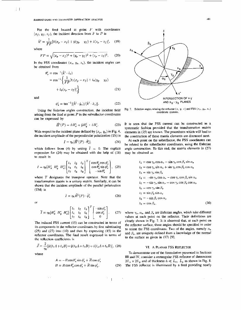
Using the Eulerian angles construction, the incident field Fig. 7. Eulerian angles relating the reflector (z, Y, 2) and FSS (zs, Us, 2s) coordinate systems.
arising from the feed at point P in the subreflector coordinates can be expressed by
* ( P ) = pH: + y q + 2H:. (23)
with respect to the incident Plane defined by ( x p , Yp) in Fig. 4, the incident amplitude of the perpendicular polarization (E) is
(24)
which follows from (4) by setting 7 = 0. The explicit expression for (24) may be obtained with the help of (18) to result in
I =qo[H: H i Hf] [ t1 t 4 iz "1 [ cosO$ sin,$Ji] , (25)
where T designates the transpose operator. Note that the transformation matrix is a unitary matrix. Similarly, it can be shown that the incident amplitude of the parallel polarization (TM) is
It is seen that the FSS current can be constructed in a systematic fashion provided that the transformation matrix elements in (25) are known. The procedures which will lead to the construction of these matrix elements are discussed next.
At each point on the subreflector, the FSS coordinates can be related to the subreflector coordinates, using the Eulerian angle construction. To this end, the matrix elements in (27) may be obtained as
I = qo[ iP(P) . & I ,
cos eg cos 4; t l = cos ys cos a, - sin y, cos p, sin a, t 2 = cos y, sin a, + sin y, cos p, cos a, t 3 = sin ys sin p, t4 = -sin ys cos a, - cos y, cos p, sin a, t 5 = -sin y, sin a, + cos y, cos p, cos a, t 6 = cos y, sin p, t7 = sin /Is sin a, t 8 = -sin pS cos a,
[ CO;&'] . (27) where y,, a,, and /I, are Eulerian angles, which take different values at each point on the reflector. Their definitions are clearly shown in Fig. 7. It is observed that, at each point on the reflector surface, these angles should be specified in order to orient the FSS coordinates. Two of the angles, namely a, and p,, are uniquely defined from a knowledge of the normal to the surface as given in (17) [9].
t 7 t 8 t 9 -sin 6:
-
I = V"EiZ(P). ljg (26)
or tg = cosp,, (30) T
- t l t2 t 3 -sin& I = qo(H: H i H;] [E; ;;
The induced FSS current (15) can be constructed in terms of its components in the reflector coordinates by first substituting (25) and (27) into (10) and then by expressing (15) in the reflector coordinates. The final result expressed in terms of the reflection coefficients is
P(tlA + t4B) + Y(t2A + t5B) + i ( t ,A + tsB)] , (28) - 2
VO VI. A PLANAR FSS REFLECTOR To demonstrate use of the formulation presented in Sections
I11 and IV, consider a rectangular FSS reflector of dimensions 2L, x 2L, and of thickness h << L,, L, as shown in Fig. 8. The FSS reflector is illuminated by a feed providing nearly
J = - [
where
A = -Rcost9:sin& +Rcosq5: B = RcosOgcosq5; +Rsin4;. (29)

482 IEEE TRANSACTIONS ON ANTENNAS AND PROPAGATION, VOL. 41, NO. 4, APRIL 1993
e-Jkor sin U sin U ~ T I - U v
= -jko4LxL ---
. { [R(cosOcosOz - 1)
) (COS O cos 0, + l)]sin($ - 4,) - (1 - T e J k o h COS 8
+ [Z(cos 0 - cos 0,)
+ ( I - TeJkohCoS ') (cos 0 + cos O~) ]COS(+ - 4,) I (32b) f Ef ,8
e-Jkor sin U sin U 47r1- U U
E,,,,, 4 = -jko4Lx L, - - -
. {2Rcos8'cos($-$')-2fisin($-@)
[ I + R - TeJkohCOSO ] COS($-@)[COSe+cosO~] -
- [f -R-TeJ ' 0 'Os '1 sin($ - @)[I +cos e cos 0'1
Fig. 8. Planar FSS reflector of thlckness h. + Ef, 4 e-j 'or sin U sin U
~ T I - U U = -jko4LxL ---
. { [R(cos Oz - cos 0)
- ( I - TeJkoh 'Os ')(cos B + cos e,)] cos($ - $z) 0.635 mm
+ [Z(COS 0 cos 0, - 1)
+ ( I - T e ~ ~ o ~ 'Os ')(cos o cos 8' + l)lsin($ - 6)
+ Ef, 4 , (33b) I
where U = koLz(cos@ sin@ - cos$sin0) and v = koLy (sin @ sin O2 - sin $ sin 0). For normal incidence, 0, = 0'. the scattered fields in the backscattered direction(0 = 0000
H ~ = 2 . 7 9 4 m m 7.1 12 mm t = 0.254 mm
Fig. 9. Single ring FSS geometry
uniform plane wave excitation in the vicinity of the FSS reflector such that
The local coordinate system for the planar FSS slab is simply (xs, y,, z,) = (2, y, z ) . Using the outlined approach, the scattered fields, as defined in (3a) and (3b) which include contributions from both the electric and magnetic surface currents, valid for both reflection and transmission cases, are
e - j k o T sin U sin v &at, 8 = -jk04LxLy 7
. { 2 ~ c o s e c ~ ~ e i sin($ - 4) + 2 ~ c o s o c o s ( $ - 4) - [ I + R - TejkohCoS8]sin(+-@)[l +cosOcos19~]
]cos( $ - @)[cos O + cos 0 7 'I + [r - E - T e j k o h COS 8
+Ef>8 (32a)
180') are expressed in terms of the reflection coefficients, R and fi. In the forward direction (0 = O'), the scattered fields are expressed in terms of the incident and transmission coefficients. For other observation angles, the scattered fields are in terms of the incident field amplitude and both the reflection and transmission matrices. In the case of an electrically thin FSS, the third and fourth terms in (32a) and (33a) may be neglected, reducing to the scattered field obtained by the approach of [ 5 ] . However, for an electrically thick FSS, these terms may not be negligible.
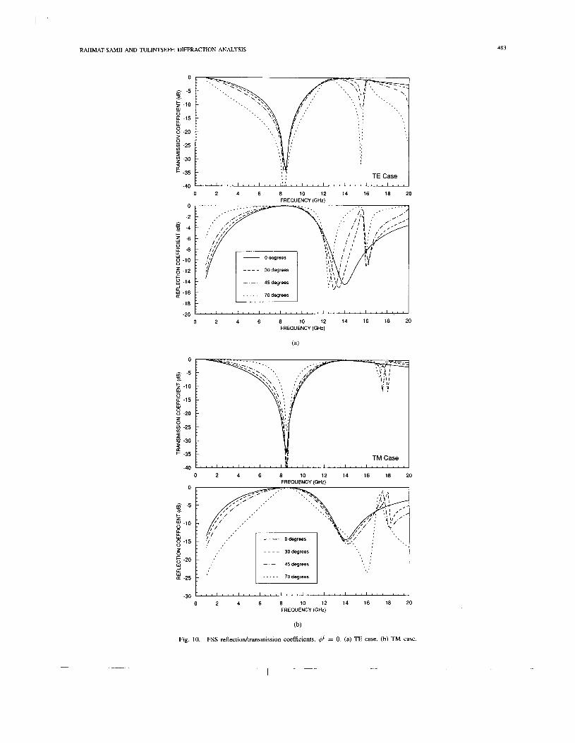
Examination the scattered fields in (32) and (33), ob- tained with no restriction on the thickness h, can provide understanding of the limits of the thin approximation given by (14). Consider the above FSS reflector to consist of periodically arranged ring elements as shown in Fig. 9. Typ- ically, frequency selective screens, having applications in microwave antenna systems as reflectors, polarizers, filters, and radomes, consist of one or more layers of a metal- lic periodic pattern embedded within material slabs for me- chanical support and electrical performance. The reflection and transmission characteristics of an FSS are generally a function of frequency, owing to the resonant behavior of the elements, and incident polarization and angle. For the configuration of Fig. 9, the reflection and transmission char- acteristics for several incident angles are shown in parts (a)
RAHMAT-SAM11 AND TULINTSEFF: DIFFRACTION ANALYSIS 483
-40 t ' " " ' " " ' " " " " " " ' " ' ' ' ' ' 0 2 4 6 8 10 12 14 16 18 20
FREQUENCY (GHz) 0
0 U -8
8 -10 5 -12 2 -14 k -16 -1
I I - - . . - 70degrees I
- l e -20 I 0 2 4 6 8 10 12 14 16 18 20
FREQUENCY (GHz)
(a)
0
m ̂ -5
5 -10
s -20
E
- 0 E -15 w
0 $ -25 3 9 -30 E -35
-40
-
TM Case
0 2 4 6 8 10 12 14 16 18 20 FREQUENCY (GHz)
-30 0 2 4 6 8 10 12 14 16 18 20
FREQUENCY (GHz)
Fig. 10. FSS reflectiodtransmission coefficients. @ = 0. (a) TE case. (b) TM case.
484 IEEE TRANSACTIONS ON ANTENNAS AND PROPAGATION, VOL. 41, NO. 4, APRIL 1993
0.7
0.6
0.5
0.4
0.3
0.2
0.1
0 0 2 4 6 8 10 12 14 16 18 20
FREWENCY (GHz)
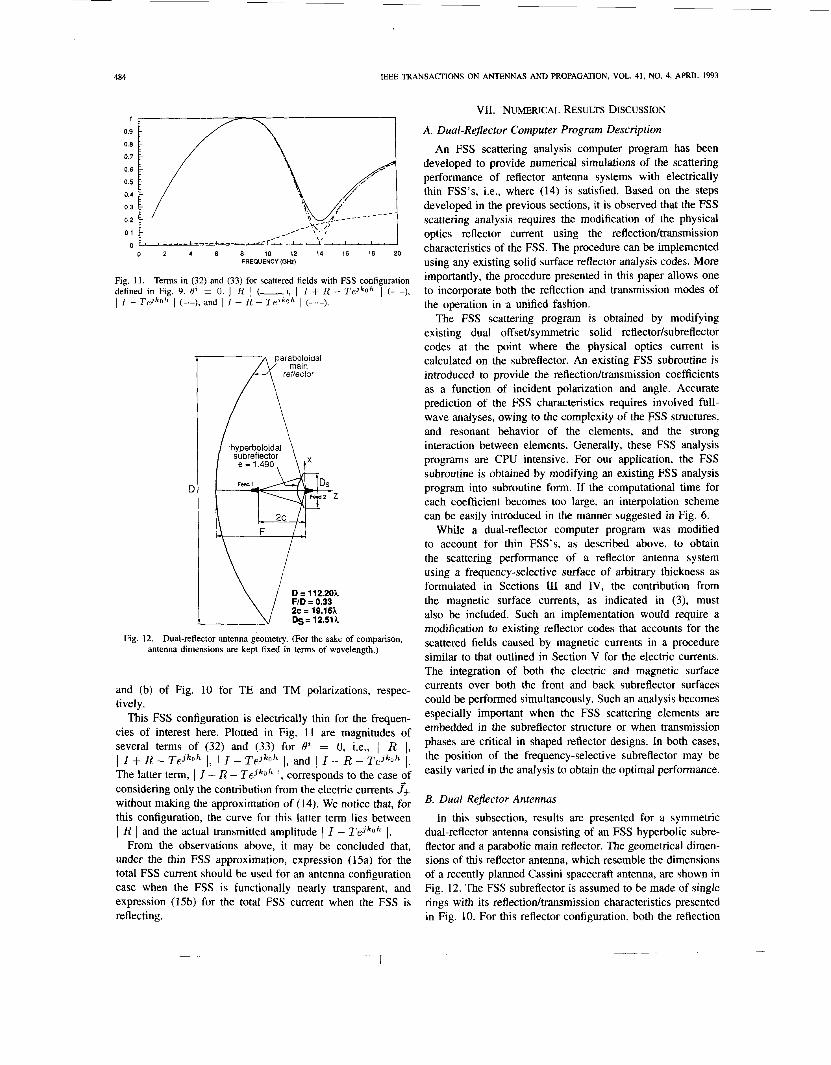
Fig. 11. Terms in (32) and (33) for scattered fields with FSS configuration defined in Fig. 9. 8' = 0. 1 R 1 (-), I I + R - Tejkoh 1 (- -), 1 I - TejkOh 1 (--), and 1 I - R - Tejkoh 1 (-..-). A reflector Eidal
hyperboloidal subreflector
e = 1.490, t X
D = 112.20h FID = 0.33 2c = 19.16h &= 12.51h
Fig. 12. Dual-reflector antenna geometry. (For the sake of comparison, antenna dimensions are kept fixed in terms of wavelength.)
and (b) of Fig. 10 for TE and TM polarizations, respec- tively.
This FSS configuration is electrically thin for the frequen- cies of interest here. Plotted in Fig. 11 are magnitudes of several terms of (32) and (33) for 02 = 0, i.e., 1 R 1, 1 I + R - Tejkoh 1, 1 I - TeJkoh 1, and I 1 - R - Tejkoh I. The latter term, I I - R - Tejko I, corresponds to the case ,Of considering only the contribution from the electric currents J& without making the approximation of (14). We notice that, for this configuration, the curve for this latter term lies between I R I and the actual transmitted amplitude 1 I - TejkOh I.
From the observations above, it may be concluded that, under the thin FSS approximation, expression (15a) for the total FSS current should be used for an antenna configuration case when the FSS is functionally nearly transparent, and expression (15b) for the total FSS current when the FSS is reflecting.
VII. NUMERICAL RESULTS DISCUSSION
A. Dual-Rejector Computer Program Description
An FSS scattering analysis computer program has been developed to provide numerical simulations of the scattering performance of reflector antenna systems with electrically thin FSS's, i.e., where (14) is satisfied. Based on the steps developed in the previous sections, it is observed that the FSS scattering analysis requires the modification of the physical optics reflector current using the reflectiodtransmission characteristics of the FSS. The procedure can be implemented using any existing solid surface reflector analysis codes. More importantly, the procedure presented in this paper allows one to incorporate both the reflection and transmission modes of the operation in a unified fashion.
The FSS scattering program is obtained by modifying existing dual offsetlsymmetric solid reflector/subreflector codes at the point where the physical optics current is calculated on the subreflector. An existing FSS subroutine is introduced to provide the reflectiodtransmission coefficients as a function of incident polarization and angle. Accurate prediction of the FSS characteristics requires involved full- wave analyses, owing to the complexity of the FSS structures, and resonant behavior of the elements, and the strong interaction between elements. Generally, these FSS analysis programs are CPU intensive. For our application, the FSS subroutine is obtained by modifying an existing FSS analysis program into subroutine form. If the computational time for each coefficient becomes too large, an interpolation scheme can be easily introduced in the manner suggested in Fig. 6.
While a dual-reflector computer program was modified to account for thin FSS's, as described above, to obtain the scattering performance of a reflector antenna system using a frequency-selective surface of arbitrary thickness as formulated in Sections I11 and IV, the contribution from the magnetic surface currents, as indicated in (3), must also be included. Such an implementation would require a modification to existing reflector codes that accounts for the scattered fields caused by magnetic currents in a procedure similar to that outlined in Section V for the electric currents. The integration of both the electric and magnetic surface currents over both the front and back subreflector surfaces could be performed simultaneously. Such an analysis becomes especially important when the FSS scattering elements are embedded in the subreflector structure or when transmission phases are critical in shaped reflector designs. In both cases, the position of the frequency-selective subreflector may be easily varied in the analysis to obtain the optimal performance.
B. Dual Rejector Antennas
In this subsection, results are presented for a symmetric dual-reflector antenna consisting of an FSS hyperbolic subre- flector and a parabolic main reflector. The geometrical dimen- sions of this reflector antenna, which resemble the dimensions of a recently planned Cassini spacecraft antenna, are shown in Fig. 12. The FSS subreflector is assumed to be made of single rings with its reflectiodtransmission characteristics presented in Fig. 10. For this reflector configuration, both the reflection
485 RAHMAT-SAM11 AND TULINTSEFF: DIFFRACTION ANALYSIS
50
45
40
- 35 ' 30 25
z k 20 a
15 0
10
5
0 -3 -2 -1 0 1 2 3
50
45
40
- 35 ' 30 2 25 g L
b
ii $ 20
15
10
5
0 -3 -2 -1 0 1 2 3
THETA (DEGREES)
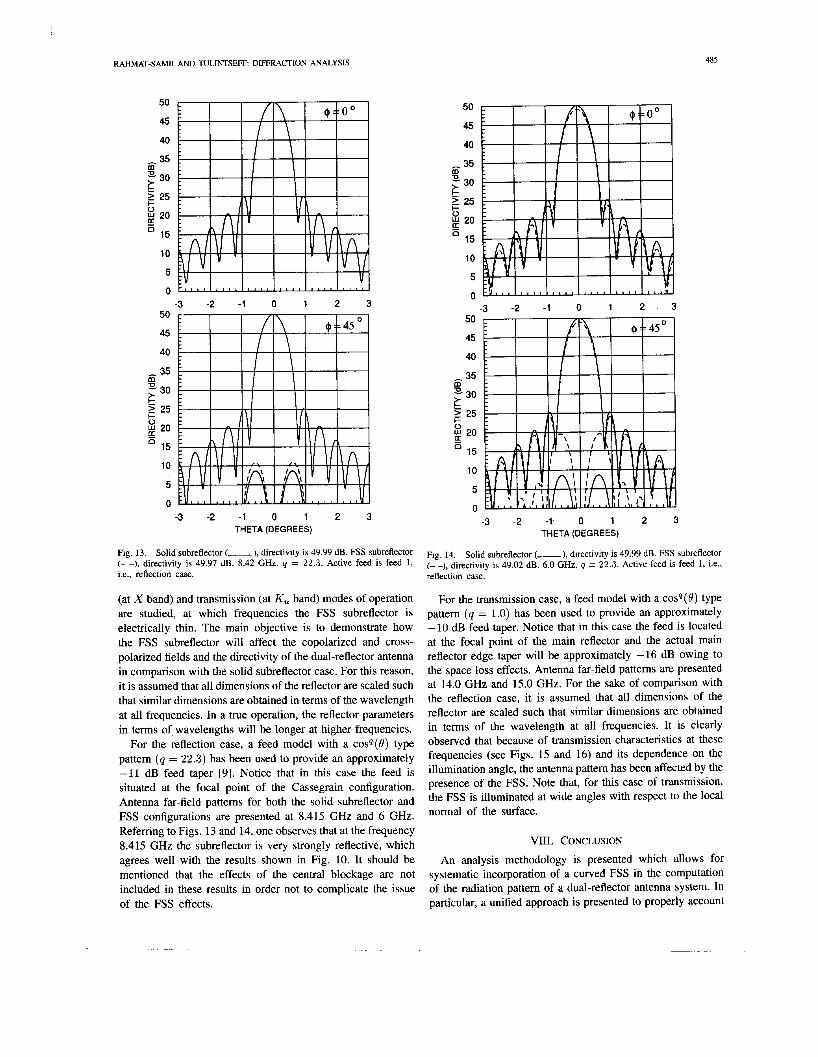
Fig. 13. Solid subreflector (-), directivity is 49.99 dB. FSS subreflector (- -), directivity is 49.97 dB. 8.42 GHz. q = 22.3. Active feed is feed 1 , i.e., reflection case.
(at X band) and transmission (at K, band) modes of operation are studied, at which frequencies the FSS subreflector is electrically thin. The main objective is to demonstrate how the FSS subreflector will affect the copolarized and cross- polarized fields and the directivity of the dual-reflector antenna in comparison with the solid subreflector case. For this reason, it is assumed that all dimensions of the reflector are scaled such that similar dimensions are obtained in terms of the wavelength at all frequencies. In a true operation, the reflector parameters in terms of, wavelengths will be longer at higher frequencies.
For the reflection case, a feed model with a cosq(t9) type pattern (y = 22.3) has been used to provide an approximately -11 dB feed taper [9]. Notice that in this case the feed is situated at the focal point of the Cassegrain configuration. Antenna far-field pattems for both the solid subreflector and FSS configurations are presented at 8.415 GHz and 6 GHz. Referring to Figs. 13 and 14, one observes that at the frequency 8.415 GHz the subreflector is very strongly reflective, which agrees well with the results shown in Fig. 10. It should be mentioned that the effects of the central blockage are not included in these results in order not to complicate the issue of the FSS effects.
50
45
40
35
30
L 25
m
g
$ 20 + o
15
10
5
E
n -3 -2 -1 0 1 2 . 3
50
45
40
35 m E 30
L 25 c $ 20 I- o
15
10
5
0
ii
-3 -2 -1. 0 1 2 3 THETA (DEGREES)
Fig. 14. Solid subreflector (-), directivity is 49.99 dB. FSS subreflector (- -), directivity is 49.02 dF3. 6.0 GHz. q = 22.3. Active feed is feed 1 , i.e., reflection case.
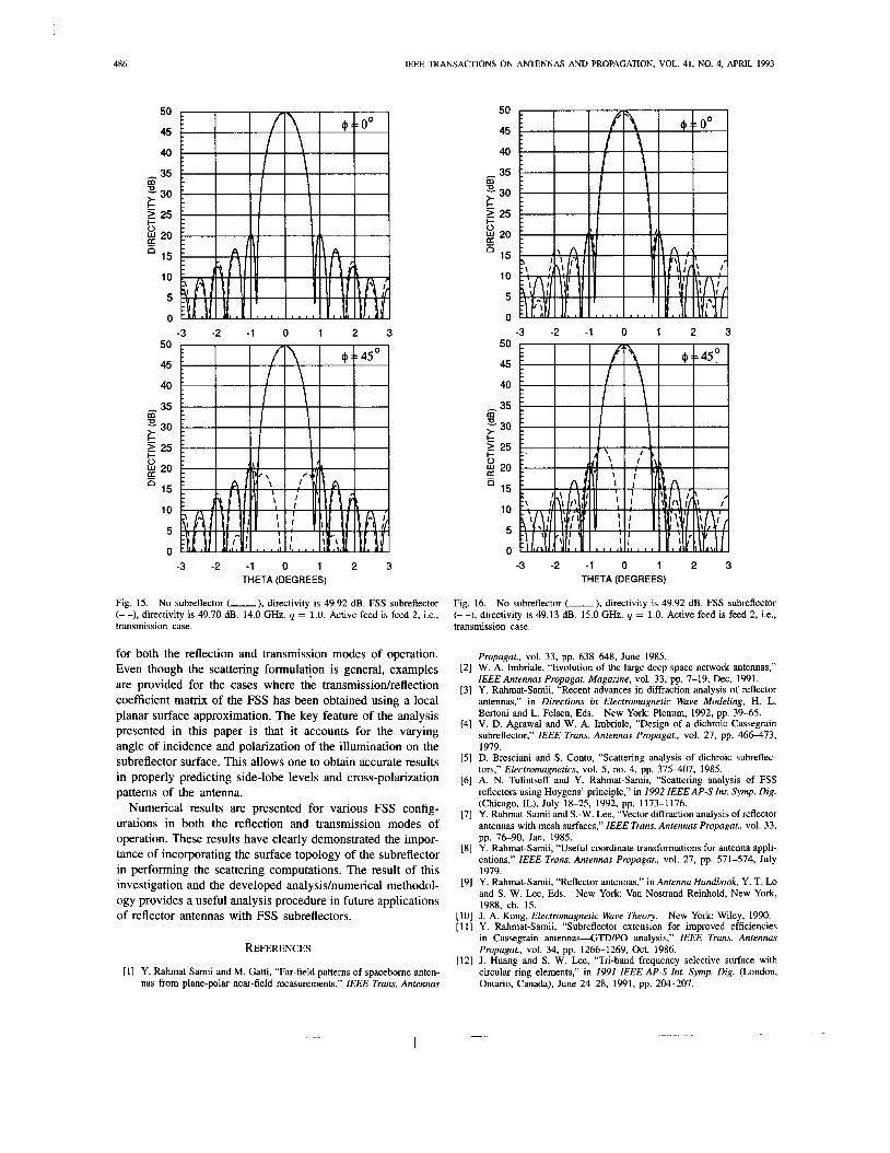
For the transmission case, a feed model with a cosq(B) type pattem (y = 1.0) has been used to provide an approximately -10 dB feed taper. Notice that in this case the feed is located at the focal point of the main reflector and the actual main reflector edge taper will be approximately -16 dB owing to the space loss effects. Antenna far-field patterns are presented at 14.0 GHz and 15.0 GHz. For the sake of comparison with the reflection case, it is assumed that all dimensions of the reflector are scaled such that similar dimensions are obtained in terms of the wavelength at all frequencies. It is clearly observed that because of transmission characteristics at these frequencies (see Figs. 15 and 16) and its dependence on the illumination angle, the antenna pattem has been affected by the presence of the FSS. Note that, for this case of transmission, the FSS is illuminated at wide angles with respect to the local normal of the surface.
VIII. CONCLUSION
An analysis methodology is presented which allows for systematic incorporation of a curved FSS in the computation of the radiation pattern of a dual-reflector antenna system. In particular, a unified approach is presented to properly account
486 IEEE TRANSACTIONS ON ANTENNAS AND PROPAGATION, VOL. 41, NO. 4, APRIL 1993
50
45
40
35 m o, 30
f 25
n
z i 20 -
15
10
5
0 -3 -2 -1 0 1 2 3
50
45
40
- 35 m
30
I 25 E ; 20 I- o
15
10
5
0
E
-3 -2 -1 0 1 2 3 THETA (DEGREES)
50
45
40
35
30
2 25
m
c ; 20 I- o
E 15
10
5
0
50
45
40
- 35 30
f 25
n
-3 -2 -1 0 1 2 3
m
z i 20 -
15
10
5
0 -3 -2 -1 0 1 2 3
THETA (DEGREES)
Fig. 15. No subreflector (-), directivity is 49.92 dB. FSS subreflector (- -), directivity is 49.70 dB. 14.0 GHz. Q = 1.0. Active feed is feed 2, i.e., transmission case. transmission case.
Fig. 16. No subreflector (-), directivity is 49.92 dB. FSS subreflector (- -), directivity is 49.13 dB. 15.0 GHz. q = 1.0. Active feed is feed 2, i.e.,
for both the reflection and transmission modes of operation. Even though the scattering formulation is general, examples are provided for the cases where the transmissiodreflection coefficient matrix of the FSS has been obtained using a local planar surface approximation. The key feature of the analysis presented in this paper is that it accounts for the varying angle of incidence and polarization of the illumination on the subreflector surface. This allows one to obtain accurate results in properly predicting side-lobe levels and cross-polarization patterns of the antenna.
Numerical results are presented for various FSS config- urations in both the reflection and transmission modes of operation. These results have clearly demonstrated the impor- tance of incorporating the surface topology of the subreflector in performing the scattering computations. The result of this investigation and the developed analysishumerical methodol- ogy provides a useful analysis procedure in future applications of reflector antennas with FSS subreflectors.
REFERENCES
[I] Y. Rahmat-Samii and M. Gatti, “Far-field patterns of spacebome anten- nas from plane-polar near-field measurements,” IEEE Trans. Antennas
Propagat., vol. 33, pp. 638-648, June 1985. W. A. Imbriale, “Evolution of the large deep space network antennas,” IEEE Antennas Propagat. Magazine, vol. 33, pp. 7-19, Dec. 1991. Y. Rahmat-Samii, “Recent advances in diffraction analysis of reflector antennas,” in Directions in Electromagnetic Wave Modeling, H. L. Bertoni and L. Felsen, Ids. V. D. Agrawal and W. A. Imbriale, “Design of a dichroic Cassegrain subreflector,” IEEE Trans. Antennas Propagat., vol. 27, pp. 46-73, 1979. D. Bresciani and S . Contu, “Scattering analysis of dichroic subreflec- tors,” Electromagnerics, vol. 5, no. 4, pp. 375407, 1985. A. N. Tulintseff and Y. Rahmat-Samii, “Scattering analysis of FSS reflectors using Huygens’ principle,” in I992 IEEEAP-S Inr. Symp. Dig. (Chicago, IL), July 18-25, 1992, pp. 1173-1176. Y. Rahmat-Samii and S.-W. Lee, “Vector diffraction analysis of reflector antennas with mesh surfaces,” IEEE Trans. Antennas Propagat., vol. 33, pp. 76-90, Jan. 1985. Y. Rahmat-Samii, “Useful coordinate transformations for antenna appli- cations,” IEEE Trans. Antennas Propagat., vol. 27, pp. 571-574, July 1979. Y. Rahmat-Samii, “Reflector antennas,” in Antenna Handbook, Y. T. Lo and S. W. Lee, Eds. New York: Van Nostrand Reinhold, New York, 1988, ch. 15. J. A. Kong, Electromagnetic Wave Theory. Y. Rahmat-Samii, “Subreflector extension for improved efficiencies in Cassegrain a n t e n n a s 4 T D P O analysis,” IEEE Trans. Antennas Propagat., vol. 34, pp. 1266-1269, Oct. 1986. J. Huang and S. W. Lee, “Tri-band frequency selective surface with circular ring elements,” in 1991 IEEE AP-S Inr. Symp. Dig. (London, Ontario, Canada), June 24-28, 1991, pp. 204-207.
New York Plenum, 1992, pp. 39-65.
New York Wiley, 1990.

RAHMAT-SAM11 AND TULINTSEFF: DIFFRACTION ANALYSIS
Yahya Rahmat-Samii (S’73-M’75-SM’79-F85) is a Professor of Electrical Engineering at the Uni- versity of California Los Angeles (UCLA). He has been a Senior Research Scientist at NASA’s Jet Propulsion Laboratory/California Institute of Tech- nology since 1978, where he contributed signif- icantly to advance antenna technology for space programs. He was a Guest Professor at the Tech- nical University of Denmark (TUD) in the summer of 1986. He has also been a consultant to many aeromace comoanies. Dr. Rahmat-Samii received
the M.S. and Ph.D. degrees in Electrical Engineering from the University of Illinois, Champaign-Urbana.
Dr. Rahmat-Samii is a fellow of IAE (1986) and was the 1984 recipient of the Henry Booker Award of URSI. He was appointed an IEEE Antennas and Propagation Society. Distinguished Lecturer and presented lectures interna- tionally. He was an elected IEEE AP-S AdCom member for the second term and has been an Associate Editor of the IEEE TRANSACTIONS ON ANTENNAS AND PROPAGATION and the Society’s Magazine. He was the Chairman of the IEEE Antennas and Propagation Society of Los Angeles in 1987/88/89. In 1989, his chapter received the best Antennas and Propagation chapter award from the AP Society. He is one of the three International Editors of the IEE book series on Electromagnetics and Antennas. He is also one of the Editors of the Joumal of Electromagnetic Waves and Applications. He is one of the Directors of AMTA (Antenna Measurement Techniques Association) and the Electromagnetic Society. He is listed in Who’s Who in America, Who’s Who in Frontiers of Science and Technology, and Who’s Who in Engineering.
Dr. Rahmat-Samii has authored or coauthored over 250 technical journal articles and conference papers and has written chapters in twelve books. He has made pioneering contributions to the developments of near-field plane- polar and bipolar antenna measurements, microwave holographic diagnostics, mobile satellite communication antennas, reflector surface compensation, multireflector antenna diffraction analysis and synthesis, scattering and ra- diation from complex objects, RCS computations, singularity in dyadic Green’s function, high-power microwave (HPM) antennas, EMP and aperture penetration, the spectral theory of diffraction (STD), and GTD. For these contributions he has received numerous NASA Certificate of Recognitions and recently earned the JPL Team NASA’s Distinguished Group Achievement Award. In 1992, he was the recipient of the Best Application Paper Award (Wheeler Award) for a paper published in the TRANSACTIONS in 1991. Dr. Rahmat-Samii is a member of Commissions A, B and J of USNCICIRSI, Sigma Xi, Eta Kappa Nu, and the Electromagnetics Academy.
487
Ann N. ’hlintseff (S’84M’90) was bom in Seattle, WA, on April 23, 1961. She received the S.B., S.M., and Ph.D. degrees from the Massachusetts Institute of Technology, Cambridge, in 1985, 1985, and 1991, respectively.
During her graduate work, she held both teaching and research assistantships. In 1986, she received the Frederick C. Hennie III Award for Excellence in Teaching and was appointed Instructor-G in the Department of Electrical Engineering and Computer Science. Currently, Dr. Tulintseff is with the Jet
Propulsion Laboratory, Pasadena, CA, in the Spacecraft Antenna Research Group. Her area of Interest is electromagnetlc wave theory and applications, with particular interest in microsmp antennas, microwave and mllimeter-wave antennas and circuit components, and numencal methods.
Dr. Tulintseff is a member of Eta Kappa Nu and Tau Beta Pi.