radiological survey of the gun forging … · orise 95/k-1 3 radiological survey of the gun forging...
TRANSCRIPT
RADIOLOGICAL SURVEY OF THE GUN FORGING MACHINE BUILDING ITHACA GUN COMPANY ITHACA, NEW YORK
T. J. VITKUS AND J. L. PAYNE
Prepared for the Office of Erivironmental Restoration U.S.‘Department of Energy

ORISE 95/K-1 3
RADIOLOGICAL SURVEY OF THE
GUN FORGING MACHINE BUILDING ITHACA GUN COMPANY
ITHACA, NEW YORK
Prepared by
T. J. Vi&us and J. L. Payne
Environme& Survey and Site Assessment Program Envirotiental and Health Sciences Group
Oak Ridge Institute for Science and Education Oak Ridge, Tennessee 37831-0117
Prepared for the
U.S. Department of Energy Offke of Environmental Restoration
FINAL REPORT
OCTOBER 1995
This report is based on work performed under contract number DE-AC05-760R00033 with the U.S. Department of Energy.

.I I I I I I I I 1 I I I ‘I I ‘I I I I 1.
RADIOLOGICAL SURVEY OF THE
GUN FORGING MACHINE BUILDING ITHACA GUN COMPANY
ITHACA, NEW YORK
Environmental Survey and Site Assessment Program
Prepared by: /.L.& @42.&L Date: 1~1 I /4g J. L@ayne, Senior Heal&‘hysics Technician Environmental Survey and Site Assessment Program
Reviewed by: M& ~I&wo..- M. J. Laudeman, Radiochemistry Laboratory Supervisor Enviromnental Survey and Site Assessment Program
Reviewed by: ,fovJPb*7ycp- Date: A. T. Payne, Administrativk Services Manager
11/r ,/ CC
Quality Assurance/Health & Safety Manager Enviromnental Survey and Site Assessment Program
Reviewed by: Date: /i/3 /CC W. L. Beck, Program Director Environmental Survey and Site Assessment Program
I I I I I, I I I. 1 1,. 1 I ,I ‘I ,I I I I I
ACKNOWLEDGMENTS
The authors would’ like to acknowledge the significant contributions of the following staff members:
FIELD STAFF
A. L. Mashbum
LABORATORY STAFF
R. D. Condra J. S. Cox M. J. Laudeman S. T. ,Shipley
CLERICAL STAFF
T. S. Fox K. E. Waters
ILLUSTRATIONS
T. D. Herrera
1 I TABLE OF CONTENTS
., ,’
ListofFigures . . . . . . . . . . . . . . . ..~......................................... ‘,
ListofTables . . . . . . . . ..‘.............~..................................
.Abbr&iations and Acronyms ........... . . . . . . . . . . . . . . . . . . . . . . . . . . . . . . . ,.
Introduction and Site History ............ . . . . . . . . . . . . . . . . . . . . . . . . . . . . . . .
SiteDescription ............................... . ...... i .......... .........
Objective ................... : .I ............ ..:. ............. c ............
Document Review . . . . .‘. . .h. . . . . . . . . . . . . ‘: . . . . . .
Procedures ..........................
Findings and Results ....................
Comparison of Results with Guidkiries . .,
summary ......... ...................
. . . . . . . . . . . . . . . ..*.............
................................
...............................
. . . . . . . . . . . ..~...................
‘References . . . . . . . . . . . . . . . . . . . . . . . . . . . . . . . . . . . . . . . . . . . :..,.............. ,:
Appendices:’
Appendix A: Major Instrumentation
Appendix B: Survey and Analytical Procedures
Appendix C: Residual Radioactive Material Guidelines Summarized from DOE Order 5400.5
.m . . . . ii
. . . 111
. . . . iv
. . . 1
2 ,. .
. 3~
. 3.
. . . . . 3,
. 6
:..” 7
. . 8
. 22
I I I I I I I I I I ,I I ,I I I I I I I
FIGURE 1:
FIGURE 2:
FIGURE 3:
FIGURE 4:
FIGURE 5 :
FIGURE 6:
FIGURE 7:
FIGURE 8:
FIGURE 9:
FIGURE 10:
LIST OF FIGURES
Location of the Ithaca Gun Company, Ithaca, New York . . . . . . . . . . . . .9
Ithaca Gun Company Site, Plot Plan - Location of the Gun Forging MachineBuilding.................................................lO
The Gun Forging Machine Building - Floor Plan . . . . . . . . . . . 11
Gun Forging Machine Building - Floor and Lower Wall Measurement and.Sampling Locations . . . . . . . . . . . . . . . . . . . . . . . . 12
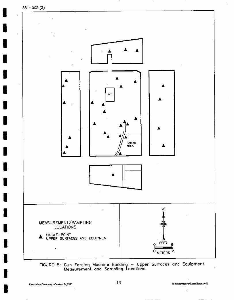
Gun Forging Machine Building - Upper Surfaces and Equipment Measurement and Sampling Locations . . .,. . . . . . . . . . . 13
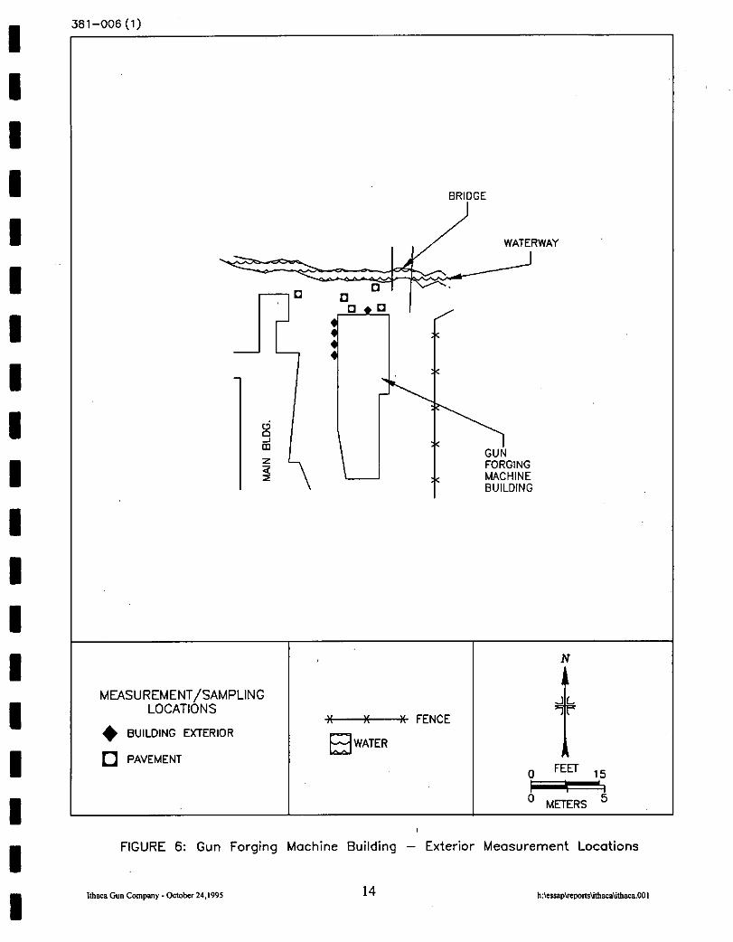
Gun Forging Machine Building - Exterior Measurement Locations . . . . . . . . 14
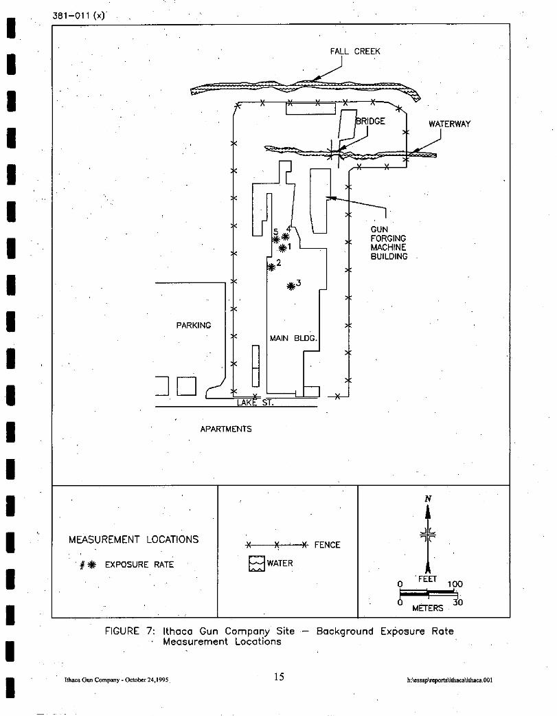
Ithaca Gun Company Site - Backgrcund Exposure Rate Measurement Locations . . . . . . . . . . . . . . . . . . . . . . . . . . . . . . . . . . . . . . . . . . . . . . . . . . . . ...15
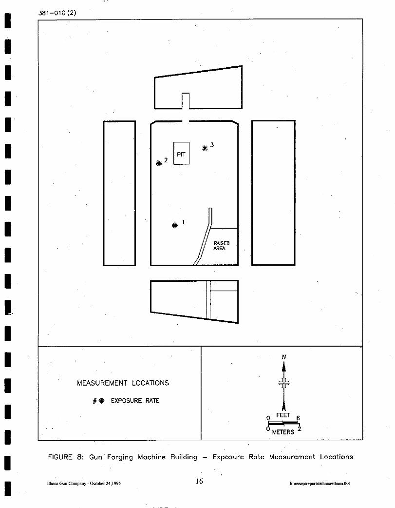
Gun Forging Machine Building - Exposure Rate Measurement Locations . 16
Ithaca Gun Company Site - Soil Sampling Locations . . . . . . . . . . . . . 17
Gun Forging Machine Building - Miscellaneous Composite Sample Locations . . . . . . . . . . . . . . . . . . . . . . . . . . . . . . . . . . . . . . . . . . . . . . . . . . . . ...18

I I LIST OF TABLES
I TABLE 1: Summary of Surface Activity Measurements : . . . . . . . . . . . . 19
I TABLE 2: Exposure Rate Measurements . . . . . . . . . . . .20
I TABLE 3: Radionuclide Concentrations in Soil Samples . . . . . . . . . . . . . . . . .21
I I I I I ,I 1 I I I I I I I
. . . 111

1 I I I I I I I I I I I I I I I I I I
Pm AEC ASME ., BKG
2 ZE dpm/lOO cm* EPA .EML ESSAP FUSRAP GM IGC kg MDA IlUll m2 Nd NIST NLO ORISE PCug
ABBREVIATIONS AND ACRONYMS
microroentgens per hour Atomic Energy Commission American Society of Mechanical Engineers background square centimeter U. S. Department of Energy disintegrations per minute per 100 square centimeters Environmental Protection Agency Environmental Measurements Laboratory Environmental Survey and Site Assessment Program Formerly Utilized Sites Remedial Action Program Geiger-Mueller Ithaca Gun Company kilogram minimum detectable activity millimeter square meter sodium iodide National Institute of Standards and Technology National Lead of Ohio Oak Ridge Institute for Science and Education picocuries per gram
iv
RADIOLOGICAL SURVEY OF THE
GUN FORGING MACHINE BUILDING ITHACA GUN COMPANY
ITHACA, NEW YORK
I
INTRODUCTION AND SITE HISTORY
I In 1961 and 1962, the Ithaca Gun Company (IGC) was subcontracted by National Lead of Ohio
(NLO) to conduct tests involving the forging of hollow uranium billets into tubes for the Atomic
I Energy Commission (AEC), predecessor agency of the U. S. Department of Energy (DOE). A
series of tests were performed in 1961 to determine the abilities of the Gun Forging Machine’s
I vertical forging unit, used by IGC in the manufacturing of shotgun barrels, to forge hollow uranium
billets into tubes for possible use as fuel cores. Additional tests to investigate alternative methods
I of producing fuel cores were conducted at IGC in 1962. The forging process involved heating the
uranium billet to extreme temperatures, followed by mechanical hammering and rapid cooling in
I quench drums. The process created residual contamination in the form of metal tilings and dust.
Because of the potential for contamination of equipment and surrounding surfaces, all testing was
I conducted in an enclosed, secluded building of the plant.
I According to information obtained from NLO justification and trip reports, approximately 164
I uranium feed stock tubes were used during the period of testing (Workhum 1961; Jansen and
Nuckels 1962). NLO controlled most aspects of the work including handling, transporting, and
I accountability of the uranium and process waste, health and safety, and post-test decontamination
efforts. IGC supplied all of the equipment, equipment operators, and special tooling required for
I the forging process. The site records indicate that NLO exercised considerable effort to minimize
contamination during the testing process. Records also indicate that monitoring of equipment,
I exhaust from dust collectors, and outdoor paved areas was performed routinely and
decontamination performed immediately if uranium contamination was detected.
I I I

I I I I I I I I I I I I I I I I I I I
Upon completion of the project in 1962, all uranium shapes, uranium-bearing dust, and
contaminated liquid and sludge were returned to NLO. The entire area, including the exterior
pavement and grounds adjacent to the testing area, were monitored and only background levels
remained after cleanup. However, records do not specify cleanup criteria or guidelines. Due to this
uncertainty, further radiological evaluation was needed to determine whether residual uranium
contamination was present in excess of DOE guidelines.
DOE reviewed available historical documentation describing the previous AEC activities conducted
at the Ithaca Gun Company site and based on the results, requested that the Environmental Survey
and Site Assessment Program (ESSAP) of the Oak Ridge Institute for Science and Education
(ORISE) perform a radiological survey of the area used for the uranium forging tests. The purpose
of the survey was to determine if residual uranium contamination was present on the property for
which DOE has authority to require remedial action under the Formerly Utilized Sites Remedial
Action Program (FUSRAP). FUSRAP was created in 1974 to identify, investigate, and cleanup
or control sites where contamination above today’s guidelines remains from the early years of the
Nation’s atomic energy program.
SITE DESCRIPTION
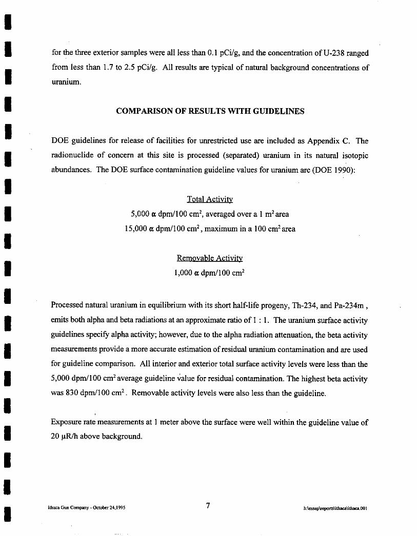
The former Ithaca Gun Company facility is located at 123 Lake Street in Ithaca, New York,
approximately 1.6 kilometers (1 mile) east of state highway 13 (Figure 1). The facility had ceased
operations in the late 1980’s and is currently unoccupied. A cyclone fence encloses the site. The
present owner of the property is State Street Associates L.P.
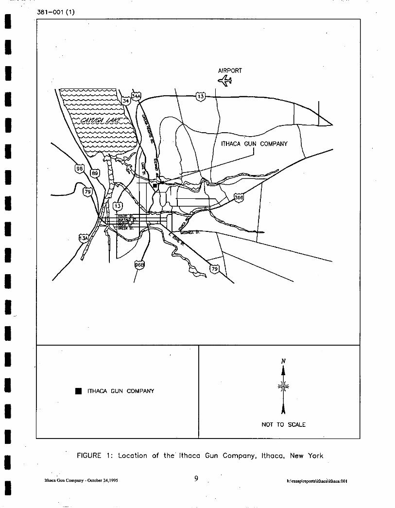
The building that formerly housed the forging machine used for the uranium tests is located at the
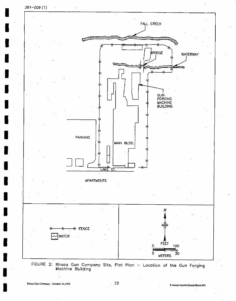
north end of the site (Figure 2). The building is constructed with concrete block walls, a sloped
wooden roof, and a concrete slab floor. The building dimensions are approximately 18 meters by
11 meters (Figure 3). Exterior areas of the building include concrete drives bordering the north,
2

I I I I I I I I I I I I I I I I I I I
east, and west, and another building is attached on the southern end of the Gun Forging Machine
Building. Drainage from this area of the site flows north and northwest to where the land drops off
sharply to a ravine that contains a creek at the base.
OBJECTIVE
The objective of this survey was to obtain suflicient data on the current radiological status, relative
to the guidelines, of the Gun Forging Machine Building at the IGC site. The DOE may then use
the acquired data to make a determination as to the need for further actions under FUSRAP.
DOCUMENT REVIEW
ESSAP reviewed available historical documentation, relative to radioactive material use at the site.
Documentation consisted primarily of NLO trip reports and project justification reports. The
information found in the ‘documents was used in the development of the survey plan that was
implemented at the site.
PROCEDURES
A survey team from ESSAP visited the IGC site and performed visual inspections and independent
measurements and sampling on July 26 and 27, 1995: Survey activities were conducted in
accordance with a survey plan submitted to and approved by the DOE (Vitkus 1995). Survey
activities included surface scans, direct measurements, smear sampling, exposure rate
measurements, and soil and residue sampling. Additional information relative to survey and
analytical equipment and procedures may be found in Appendices A and B. A representative from
the New York State Department of Environmental Conservation accompanied ESSAP personnel
during the course of this survey and provided their findings in a separate correspondence (Merges
1995).
3
I I I I I I I I I I I I I I I I I I I
REFERENCE SYSTEM
Measurement and sampling locations were referenced to prominent building or site features.
SURFACE SCANS
Surface scans for gamma and beta activity were performed on 100 percent of the floor, lower walls
(up to 2 m), and adjacent exterior surfaces. In addition, approximately 20 percent of overhead
surfaces that included I-beams, pipes, ledges, a crane track, and exhaust fans were also scanned,
with more concentrated scans in the area above the suspected previous location of the forging
machine. Surface scans were performed using Nal scintillation, gas proportional, and/or GM
detectors coupled to ratemeters or ratemeter-scalers with audible indicators.
SURFACE ACTIVITY MEASUREMENTS
Processed natural uranium emits both alpha and beta radiation in approximately equal proportions.
Because alpha radiation is selectively attenuated by rough, damp, or dirty surfaces, beta radiation
measurements provide a more representative indication of residual uranium surface activity levels.
Direct measurements for total beta activity were performed at 30 locations on the floor and lower
walls. Direct measurements’were also performed on equipment surfaces and upper surfaces at 30
locations, and at a total of 10 locations on exterior building and paved surfaces. Smear samples for
determining removable gross alpha and gross beta contamination were collected at each direct
measurement location. Figures 4 through 6 show measurement and sampling locations.
EXPOSURE RATE MEASUREMENTS
Background interior exposure.rate measurements were performed at five locations in the main plant
building in an area of similar construction (although no other areas were located that were
constructed with the firebrick found in the Gun Forging Machine Building), but without a history
I 1 I I I I I I I I I I I I I I I I \ s
of radioactive materials use (Figure 7). Exposure rates were measured at three locations within the
Gun Forging Machine Building (Figure 8). Exposure rates were measured at 1 meter above the
surface using’s pressurized ionization chamber.
SOIL SAMPLING
Probable drainage pathways from the exterior paved surfaces were traced to the point that soil,
sediment, or other type of potential contaminant sink was encountered. Surface (O-l 5 centimeter)
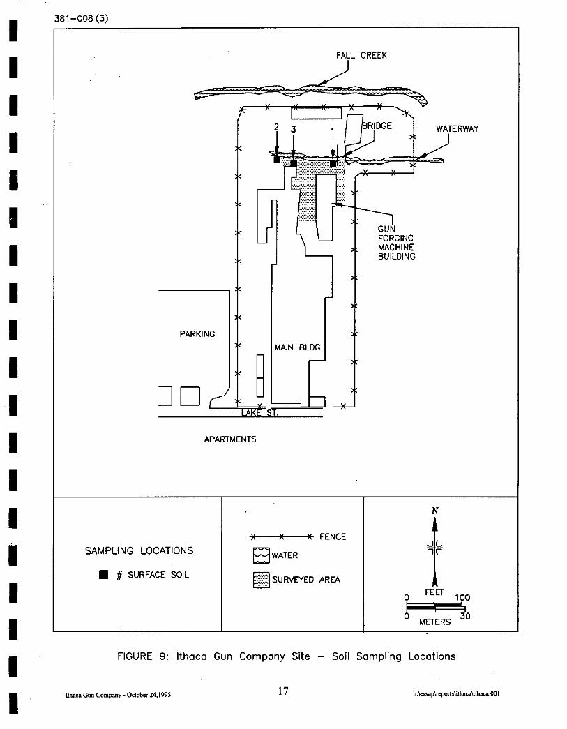
soil samples were then collected from three locations (Figure 9). Sample locations included an area
on the side.of the ravine ,beneath a dram pipe that appeared to lead from the Gun Forging Machine
Building (location # 1), a water settling area at the bottom of the ravine (location # 2), and at a
location on top of the ravine where water was channeled from the paved area through a retaining
wall and into the ravine (location #3). Exposure rate measurements could not be performed at these
locations due, to the steep terrain, although direct gamma measurements were made at each
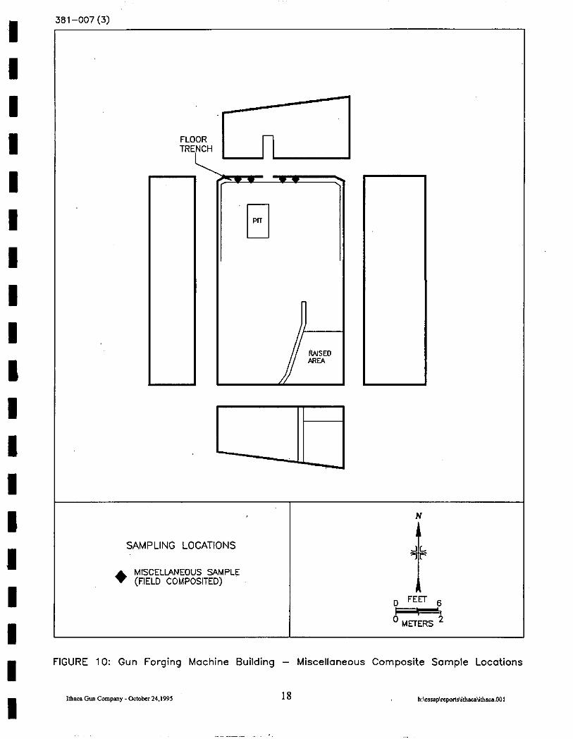
sampling location using a NaI scintillation detector coupled to a ratemeter. One composite sample
of material (soil, residue, etc.) was collected from a french drain at the interior base of the north
wall (Figure 10).
SAMPLE ANALYSIS AND DATA INTERPRETATION
Samples and survey data were returned to ORISE’s ESSAP laboratory in Oak Ridge, Tennessee
for analysis and interpretation. Soil and trench residue samples were analyzed by solid state g-a
spectrometry. Spectra were reviewed for U-235 and U-238 and any other identifiable photopeaks
and results reported in picocuries per gram (pCi/g). Smears were analyzed for gross alpha and gross
beta activity using a low background proportional counter. Smear data and direct measurement data
were converted to units of disintegrations per minute per 100 square centimeters (dprn/lOO cm*).
Exposure rates were reported in microroentgens per hour @R/h). Additional information
concerning major instrumentation, sampling equipment, and analytical procedures is provided in
Appendices A and B. Results were compared to the DOE guidelines which are provided in
Appendix C.

I I I I I I I I I I I I I I I I I I I
FINDINGS AND RESULTS
SURFACE SCANS
Surface scans for gamma and beta radiation did not identify any locations of elevated direct
radiation indicative of residual contamination on surfaces within the Gun Forging Machine Building
or on exterior portions of the facility.
SUFWACE ACTIVITY LEVELS
The results of total and removable activity levels are summarized in Table 1. Total beta activity
ranged from less than 160 to 620 dpm/lOO cm’ on interior building surfaces and were less than 830
dpm/lOO cm2 on the exterior building and paved surfaces. Removable activity levels were all less
than the minimum detectable activity levels of the procedure which were 12 dpm/lOO cm2 for gross
alpha and 16 dprn/l 00 cm* for gross beta.
EXPOSURE RATES
Interior exposure rates are presented in Table 2. Background exposure rates ranged from 10 to 12
uR/h, and averaged 11 uR/b. Exposure rates measured in the Gun Forging Machine Building
ranged from 12 to 14 uR/h. The slight above background increase in exposure rates observed in
the Gun Forging Machine Building was the result of the presence of tire brick, which contains
naturally occurring elevated levels of gamma emitting radionuclides.
RADIONUCLIDE CONCENTRATIONS IN SOIL SAMPLES
Radionuclide concentrations in the interior composite trench sample and the three exterior surface
soil samples are summarized in Table 3. The concentrations of U-235 and U-238, in the trench
sample were less than 0.1 pCi/g and less than 1.6 pCi/g, respectively. The concentration of U-235,
6
I I I I I I I I I I I I I I I I I I I
for the three exterior samples were all less than 0.1 pCi/g, and the concentration of U-238 ranged
from less than 1.7 to 2.5 pCi/g. All results are typical of natural background concentrations of
uraniunl.
COMPARISON OF RESULTS WITH GUIDELINES
DOE guidelines for release of facilities for unrestricted use are included as Appendix C. The
radionuclide of concern at this site is processed (separated) uranium in its natural isotopic
abundances. The DOE surface contamination guideline values for uranium are (DOE 1990):
Total Activitv
5,000 a dpm/lOO cm*, averaged over a 1 mrarea
15,000 a dpm/lOO cm*, maximum in a 100 cmrarea
Removable Activitv
1,000 a dpm/lOO cm*
Processed natural uranium in equilibrium with its short half-life progeny, Th-234, and Pa-234m,
emits both alpha and beta radiations at an approximate ratio of 1 : 1. The uranium surface activity
guidelines specify alpha activity; however, due to the alpha radiation attenuation, the beta activity
measurements provide a more accurate estimation of residual uranium contamination and are used
for guideline comparison. All interior and exterior total surface activity levels were less than the
5,000 dprn/l 00 cm’ average guideline value for residual contamination. The highest beta activity
was 830 dpm/lOO cm2. Removable activity levels were also less than the guideline.
Exposure rate measurements at 1 meter above the surface were well within the guideline value of
20 @II above background.

.I I I I I I I I I, I I I I I I I I I I
Guidelines for residual uranium concentrations in soil are developed on a site-specific basis only
for those sites where above background uranium contamination is present. Uranium concentrations
in the composite interior trench sample and the three exterior surface soil samples collected from
the site are all typical of background levels of uranium from this region of the country.
SUMMARY
On July 26 and 27, 1995, ESSAP performed a radiological survey of the Gun Forging Machine
Building at the former Ithaca Gun Company facility in Ithaca, New York. The survey activities
included surface scans, measurements for total and removable surface activity, exposure rate
measurements, and interior and exterior soil/residue sampling. No residual surface activity,
approaching DOE guidelines, was detected on interior or exterior surfaces. Exposure rates were
all within the guideline value, and uranium concentrations in soil/residue samples were all typical
of uranium background levels.
8
I
I I I
I -
I I I I I
I I
,’
381-001 (11 ,
AIRPORT
+
N
JL n ITHACA GUN COMPANY
i-
NOT TO SCALE
FIGURE 1: Location of the’ Ithaca Gun Company, Ithaca, New York
I I I I ,I I I I I 1 I I I I I I I I I
381-009 (1)
: FALL CREEK
APARTMENTS
Tii--+ FENCE WATER
‘.
FIGURE 2: lthaco Gun Company Site, Plot Plan - Location of the Gun Forging Machine Building
381-002 (3)
-1
SVSPECTED LOCAnON OF FORCING
N
0 FEET 6
1
FIGURE 3: Gun Forging Machine Building - Floor Plan

I I I I I I I I I I I I I I I I I I I
N
MEASUREMENT/SAMPLING LOCATIONS
. SINGLE-POINT LOWER WALLS AND FLOOR
’ METERS ’
FIGURE 4: Gun Forging Machine Building’ - Floor and Lower Wall Measurement and Sampling Locations
JO I -vv.J \L)
N
MEASUREMENT/SAMPLING LOCATIONS
A SINGLE-POINT UPPER SURFACES AND EQUIPMENT
FIGURE 5: Gun Forging Machine Building - Upper Surfaces and Equipment Measurement and Sampling Locations
nhaca Gun company - actobcr 24JW 13 h:~~*~*m~fhaca.001
381-008 (1)
BRIDGE
MEASUREMENT/SAMPLING LOCATIONS
+ BUILDING EXTERIOR
q PAVEMENT
e FENCE
E3 WATER
02
’ METERS 5
FIGURE 6: Gun Forging Machine Building - Exterior Measurement Locations
- - - \ ., ,,
FALL CREEK ,’
APARTMENTS
MEASUREMENT LOCATIONS X FENCE
#x EXPOSURE RATE
FIGURE 7: Ithaca Gun Company Site - Background Excosure Rate “. Measurement Locations
‘I I. I I, I’ I I I I I I, 1 1 I I I I I I I
381-010 (2)
MEASUREMENT LOCATIONS
#;lk EXPOSURE RATE
FIGURE 8: Gun’ Forging Machine Building - Exposure Rate Measurement Locations
381-008 (3)
FALL CREEK
PARKING
APARTMENTS
N
M FENCE
SAMPLING LOCATIONS ET3 WATER
H # SURFACE SOIL q SURVEYED AREA
FIGURE 9: Ithaca Gun Company Site - Soil Sampling Locations
,!haca Gun Company - onobsr 24,,995 17 h:\crrsp\rspon~~i\iU1aca\iUlacs.001
I I I I I I I I I I I I I I 1 I I I 1~
381-007 (3)
I-
-I? RASED AREA
ul SAMPLING LOCATIONS
1 ’ METERS ’
FIGURE 10: Gun Forging Machine Building - Miscellaneous Composite Sample Locations
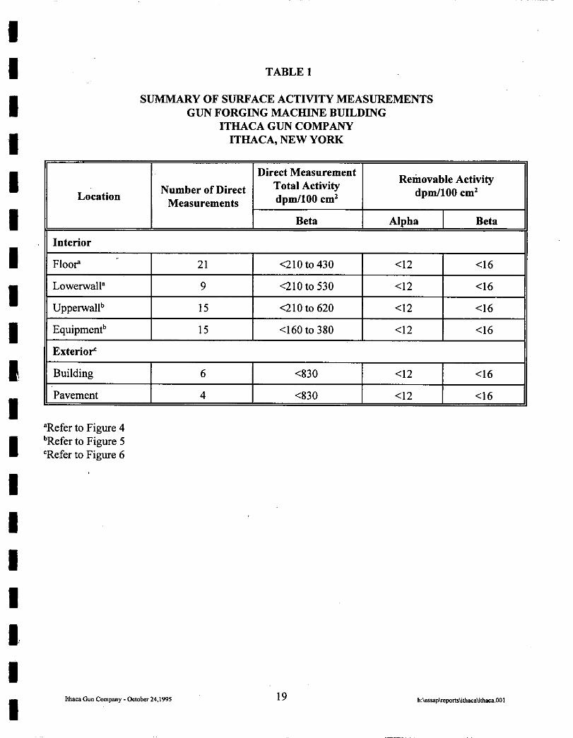
TABLE 1
SUMMARY OF SURFACE ACTIVITY MEASUREMENTS GUN FORGING MACHINE BUILDING
ITHACA GUN COMPANY ITHACA, NEW YORK
Location
Direct Measurement Total Activity Redaovable Activity
Number of Direct dpmllO0 cm* dpm/lOO cm2
Measurements
Interior
Beta Alpha Beta
21 I <210to430 I Cl2 I 46 11 I <210 to 530 I Cl2 I 46 11 II Lowerwall” 9
II UpperwalP I 15 I QlOto620 I <12 I~~- ~16-71
Equipmentb
Exteriof
Building
15 <I60 to 380
6 ~830
Pavement 4 <830 Cl2 ~16
“Refer to Figure 4 bRefer to Figure 5 “Refer to Figure 6
19

TABLE 2
EXPOSURE RATE MEASUREMENTS GUN FqRGING MACHINE BUILDING
ITHACAGUNCOMPANY ITHACA, NEW YORK
Location
Background*
1
2
3
4
5
Gun Forging Machine Buildingb
1
2
3
1 Exposure Rate at 1 meter @R/h)
11
11
,lO
.’ 11
12
14
12
14
“Refer to Figure 7 bRefer to Figure 8
20

I I I I I I I I I If I I I I I I I I I
TABLE 3
RADIONUCLIDE CONCENTRATIONS IN SOIL SAMPLES
GUN FORGING MACHINE BUILDING ITHACA GUN COMPANY
ITHACA, NEW YORK
Location
Exterior” - Location 1
Exterior - Location 2
Exterior - Location 3
Radionuclide Concentrations (pCi/g)
U-235 U-238
co.1 4.7
co.1 2.5 f 1.5’
co.1 0.9 f 1.1
Interio? - Trench Composite co.1 4.6 II
“Refer to Figure 9 bRefer to Figure 10 cUncertainties represent the 95% confidence level, based only on counting statistics.
21
I I I I I I I I I I I I I I I I I I I
REFERENCES
DOE, 1990. DOE Order 5400.5, Radiation Protection of the Public and Environment. June 5, 1990.
Jansen, R.J. and Nuckels, J.G., 1962. Trip Report to the Ithaca Gun Company, Ithaca, New York, on May 21 through June 8,1962. Memorandum to S. Marshall, National Lead of Ohio. July 26, 1962.
Merges, P.J. (NYDEC) 1995. Letter to M. Finklestein (State Street Associates L.P. II). September 8, 1995.
Vitkus, T. J., (ORISE) 1995. Letter to W. Alexander Williams (DOE/HQ). July 24, 1995.
WorkhumA.D., 1961. Trip Report to the Ithaca Gun Company, Ithaca, New York, June 19-30 and July 4-7, 1961. Memorandum to J.A. Quigley, MD, National Lead of Ohio. July 28, 1961.
22
I I I I I I I I I 1 I I I I I I I 1 I
Ithaca Glm comwy -on0bcr24,I595
APPENDIX A
MAJOR INSTRUMENTATION

I I APPENDIX A
I I
MAJOR INSTRUMENTATION
The display of a.specific product is not to be construed as an endorsement of the product or its manufacturer by the authors or their employers.
I d I I
DIRECT RADIATION MEASUREMENT
Instruments
Eberline Pulse Ratemeter Model PRM-6 (Eberline, Santa Fe, NM)
Ludlum Floor Monitor Model 239-l (Ludlum Measurements, Inc.,
I Sweetwater, TX)
Ludlum Ratemeter-Scaler
I Model 222 1 (Ludlum Measurements, Inc., Sweetwater, TX)
I Detectors
I Eberline GM Detector Model HP-260
I Effective Area, 20 cm2 (Eberline, Santa Fe, NM)
I Ludlum Gas Proportional Detector Model 43-37 Effective Area, 550 cm*
I (Ludlum Measurements, Inc., Sweetwater, TX)
I Ludlum Gas Proportional Detector Model 43-68 Effective Area, 126 cm*
I (Ludlum Measurements, Inc., Sweetwater, TX)
A-l

I I I I I .I I I I I I I I I I I I I I
Reuter-Stokes Pressurized Ion Chamber Model RSS-111 (Reuter-Stokes, Cleveland, OH)
Victoreen Nal Scintillation Detector Model 489-55 3.2 cm x 3.8 cm Crystal (Victoreen, Cleveland, OH)
LABORATORY ANALYTICAL INSTRUMENTATION
High Purity Extended Range Intrinsic Detectors Model No: ERVDS30-25195 (Tennelec, Oak Ridge, TN) Used in conjunction with: Lead Shield Model G-l 1 (Nuclear Lead, Oak Ridge, TN) and Multichannel Analyzer 3 100 Vax Workstation (Canberra, Meriden, CT)
Low Background Gas Proportional Counter Model LB-5 100-W (Oxford, Oak Ridge, TN)
A-2
I I I I I If I’ I I I I I I I llhca GM company - ostobn 24.1995
APPENDIX B
SURVEY AND ANALYTICAL PROCEDURES

I I I I ‘I I I I I I I I I I I I I I I
APPENDIX B
SURVEY AND ANALYTICAL PROCEDURES
SURVEY PROCEDURES
Surface Scans
Surface scans were performed by passing the probes slowly over the surface; ‘the distance between
the probe and the surface was maintained at a minimum - nominally about 1 cm. A large surface
area, gas proportional floor monitor was used to scan the floors of the surveyed areas. Other
surfaces were scanned using small area (20 cm’, 126 cm*) hand-held detectors. Identification of
elevated levels was based on increases in the audible signal from the recording and/or indicating
instrument. Combinations of detectors and instruments used for the scans were:
Alpha-Beta - gas proportional detector with ratemeter-scaler
Beta gas proportional detector with ratemeter-scaler
pancake GM detector with ratemeter-scaler
G-a - NaI scintillation detector with ratemeter
Surface Activitv Measurements
Measurements of total beta activity levels were primarily performed using gas proportional
detectors with portable ratemeter-scalers. Beta activity measurements were performed on upper
room surfaces, some equipment, and exterior surfaces, using gas proportional and/or GM detectors
with ratemeter-scalers.
B-l
I I I I I I I I I I I I I I I I I I I
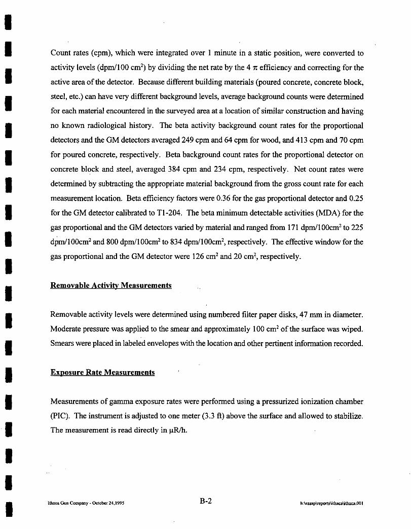
Count rates (cpm), which were integrated over 1 minute in a static position, were converted to
activity levels (dpm/lOO cm*) by dividing the net rate by the 4 n efficiency and correcting for the
active area of the detector. Because different building materials (poured concrete, concrete block,
steel, etc.) can have very different background levels, average background counts were determined
for each material encountered in the surveyed area at a location of similar construction and having
no known radiological history. The beta activity background count rates for the proportional
detectors and the GM detectors averaged 249 cpm and 64 cpm for wood, and 413 cpm and 70 cpm
for poured concrete, respectively. Beta background count rates for the proportional detector on
concrete block and steel, averaged 384 cpm and 234 cpm, respectively. Net count rates were
determined by subtracting the appropriate material background from the gross count rate for each
measurement location. Beta efficiency factors were 0.36 for the gas proportional detector and 0.25
for the GM detector calibrated to Tl-204. The beta minimum detectable activities (MDA) for the
gas proportional and the GM detectors varied by material and ranged from 171 dpm/lOOcmz to 225
dprn/lOOcmz and 800 dpm/100cm2 to 834 dpm/lOOcmz, respectively. The effective window for the
gas proportional and the GM detector were 126 cm2 and 20 cm?, respectively.
Removable Activitv Measurements
Removable activity levels were determined using numbered filter paper disks, 47 mm in diameter.
Moderate pressure was applied to the smear and approximately 100 cm* of the surface was wiped.
Smears were placed in labeled envelopes with the location and other pertinent information recorded.
Exaosure Rate Measurements ’
Measurements of g-a exposure rates were performed using a pressurized ionization chamber
(PIG). The instrument is adjusted to one meter (3.3 ft) above the surface and allowed to stabilize.
The measurement is read directly in pR/h.
B-2
I I I I I I I I I I I I I I I I I I I
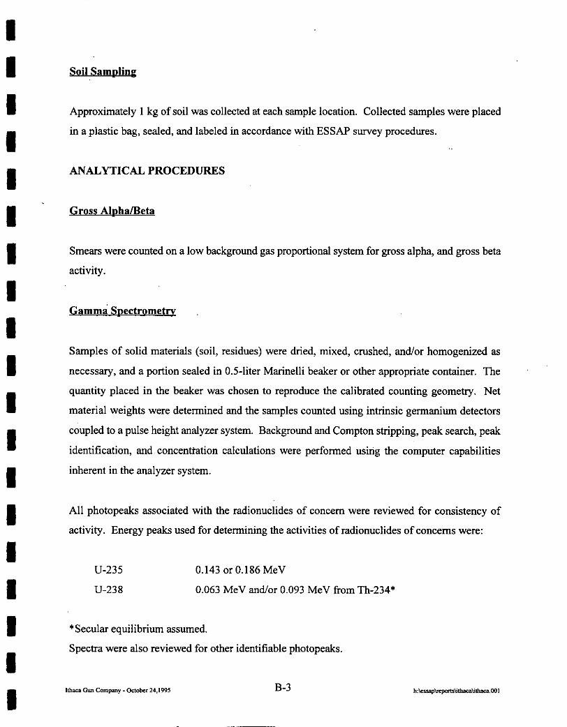
Soil Samding
Approximately 1 kg of soil was collected at each sample location. Collected samples were placed
in a plastic bag, sealed, and labeled in accordance with ESSAP survey procedures.
ANALYTICAL PROCEDURES
Gross Aloha/Beta
Smears were counted on a low background gas proportional system for gross alpha, and gross beta
activity.
Gamma Soectrometry
Samples of solid materials (soil, residues) were dried, mixed, crushed, and/or homogenized as
necessary, and a portion sealed in OS-liter Marinelli beaker or other appropriate container. The
quantity placed in the beaker was chosen to reproduce the calibrated counting geometry. Net
material weights were determined and the samples counted using intrinsic germanium detectors
coupled to a pulse height analyzer system. Background and Compton stripping, peak search, peak
identification, and, concenttation calculations were performed using the computer capabilities
inherent in the analyzer system.
All photopeaks associated with the radionuclides of concern were reviewed for consistency of
activity. Energy peaks used for determining the activities of radionuclides of concerns were:
U-235 0.143 or 0.186 MeV
U-238 0.063 MeV and/or 0.093 MeV from Th-234*
*Secular equilibrium assumed.
Spectra were also reviewed for other identifiable photopeaks.

I I I I I I I I I I I I I I I I I ‘I I
UNCERTAINTIES AND DETECTION LIMITS
The uncertainties associated with the analytical data presented in the tables of this report represent
the 95% confidence level for that data. These uncertainties were calculated based on both the gross
sample count levels and the associated background count levels. Additional uncertainties,
associated with sampling and measurement procedures, have not been propagated into the data
presented in this report.
Detection limits, referred to as minimum detectable activity (MDA), were based on 2.71 plus 4.65
times the standard deviation of the background count [2.71 + 4.65JBKGl. When the activity was
determined to be less than the MDA of the measurement procedure, the result was reported as less
than MDA. Because of variations in background levels, measurement efftciencies, and
contributions from other radionuclides in samples, the detection limits differ from sample to sample
and instrument to instrument.
CALIBRATION AND QUALITY ASSURANCE
Calibration of all field and laboratory instrumentation was based on standards/sources, traceable
to NIST, when such standard/sources were available. In cases where they were not available,
standards of an industry recognized organization were used. Calibration of pressurized ionization
chambers was performed by the manufacturer.
Analytical and field survey activities were conducted in accordance with procedures from the
following documents of the Environmental Survey and Site Assessment Program:
l Survey Procedures Manual, Revision 9 (April 1995)
l Laboratory Procedures Manual, Revision 9 (January 1995)
l Quality Assurance Manful, Revision 7 (January 1995)
I I The procedures contained in these manuals were developed to meet the requirements of DOE Order
I 5700.6C and ASMB NQA-1 for Quality Assurance and contain measures to assess processes during
their performance.
I Quality control procedures include:
I - Daily instrument background and check-source measurements to confirm that equipment
I operation is within acceptable statistical fluctuations.
l Participation in EPA and EML laboratory Quality Assurance Programs.
I l Training and certification of all individuals performing procedures.
l Periodic internal and external audits.
I I I I I I I I I I I I
B-5
APPENDIX C
RESIDUAL RADIOACTIVE MATERIAL GUIDELINES
SUMMARIZED FROM DOE ORDER 5400.5
I I I I I I I I I I I I I I I I I I I Ithaca Gun Campany - octobcr 24.IW5

I I I
APPENDIX C
RESIDUAL RADIOACTIVE MATERIAL GUIDELINES SUMMARIZED FROM DOE ORDER 5400.5
I. BASIC DOSE LIMITS
I The basic limit for the annual radiation dose (excluding radon) received by an individual member of
I the general public is 100 mremyr. In implementing this limit, DOE applies as low as reasonable
achievable principles to set site-specific guidelines.
I STRUCTti GUIDELINES
I Indoor/Outdoor Structure Surface Contamination
I Allowable Total Residual Surface Contamination
I (dpm/l 00 cm2)b
Radionuclides” Average”+’ Maximurnd’ Removable’
I Transuranics, Ra-226, Ra-228,
I Th-230 Th-228, Pa-23 1, AC-227, I-125,1-129 8 100 300 20
I Th-Natural, Th-232, Sr-90, Ra-223, Ra-224, U-232,
I I-126, I-131, I-133 ) ,000 3,000 200
U-Natural, U-23.5, U-238, and
I associated decay products 5,000a 15,OOOa 1,OOOa
Beta-gamma emitters (radionuclides
I with decay modes other than alpha emission or spontaneous fission) except Sr-90 and others
I noted above h 5,ooop-y 15,ooop-y 1 ,ooop-y
I I I I I I I I I I I I I I I I I I’ I
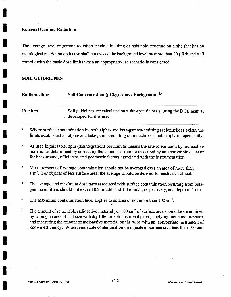
External Gamma Radiation
The average level of gamma radiation inside a building or habitable structure on a site that has no
radiological restriction on its use shall not exceed the background level by more than 20 pR/h and will
comply with the basic dose limits when an appropriate-use scenario is considered.
SOIL GUIDELINES
Radionuclides Soil Concentratidn (pCi/g) Above Background’J*’
Uranium Soil guidelines are calculated on a site-specific basis, using the DOE manual developed for this use.
Where surface contamination by both alpha- and beta-gamma-emitting radionuclides exists, the limits established for alpha- and beta-gamma-emitting radionuclides should apply independently.
As used in this table, dpm (disintegrations per minute) means the rate of emission by radioactive material as determined by correcting the counts per minute measured by an appropriate detector for background, efficiency, and geometric factors associated with the instrumentation.
Measurements of average contamination should not be averaged over an area of more than 1 m*. For objects of less surface area, the average should be derived for each such object.
The average and maximum dose rates associated with surface contamination resulting from beta- g-a emitters should not exceed 0.2 mrad/h and 1.0 mrad/h, respectively, at a depth of 1 cm.
The maximum contamination level applies to an area of not more than 100 cm2.
The amount of removable radioactive material per 100 cm’ of surface area should be determined by wiping an area of that size with dry filter or soft absorbent paper, applying moderate pressure, and measuring the amount of radioactive material on the wipe with an appropriate instrument of known efficiency. When removable contamination on objects of surface area less than 100 cm2
c-2

I I I I I I I I I I I I I I I I I I I
is determined, the activity per unit area should be based on the actual area and the entire surface should be wiped. It is not necessary to use wiping techniques to measure removable contamination levels, if direct scan surveys indicate that total residual surface contamination levels are within the limits for removable contamination.
Guidelines for these radionuclides are not given in DOE Order 5400.5; however, these guidelines are considered applicable until guidance is provided.
This category of radionuclides includes mixed fission products, including the Sr-90 which is present in them. It does not apply to Sr-90, which has been separated from the other fission products, or mixtures where the Sr-90 has been enriched.
These guidelines take into account ingrowth of radium-226 from thorium-230 or thorium-232 and radium-228 and assume secular equilibrium. If either Th-230 and Ra-226 or Th-232 and Ra-228 are both present, not in secular equilibrium, the guidelines apply to the higher concentration. If other mixtures of radionuclides occur, the concentrations of individual radionuclides shall be reduced so that (1) the dose for the mixtures will not exceed the basic dose limit, or (2) the sum of ratios of the soil concentration of each radionuclide to the allowable limit for that radionuclide will not exceed 1 (“unity”).
These guidelines represent allowable residual concentrations above background averaged across any 15-cm-thick layer to any depth and over any contiguous 100 m* surface area.
If the average concentration in any surface or below-surface area, less than or equal to 252m , exceeds the authorized limit of guideline by a factor of (100/A)“, where A is the area or the elevated region in square meters, limits for “hot spots” shall also be applicable. Procedures for calculating these hot spot limits, which depend on the extent of &elevated local concentrations, are given in the DOE Manual for Implementing Residual Radioactive Materials Guidelines, DOEKW8901. In addition, every reasonable effort shall be made to remove any source of radionuclide that exceeds 30 times the appropriate limit for soil, irrespective of the average concentration in the soil.
c-3
I I REFERENCES
I “U.S. Department of Energy Guidelines for Residual Radioactive Material at Formerly Utilized Sites Remedial Action Program and Remote Surplus Facilities Management Program Sites,” Revision 2,
I March 1987.
I “DOE Order 5400.5, Radiation Protection of the Public and the Environment,” February 1990.
I I I I I I I I I I I I I I C-4