radiological safety considerations of a 40 kw 35 mev … · 1 radiological safety considerations of...
TRANSCRIPT

1
Radiological Safety Considerations of a 40 kW 35 MeV Electron Linear Accelerator at the Canadian Light Source
P. Chowdhury1 and M. Benmerrouche1 1Canadian Light Source Inc., 44 Inovation Boulevard, Saskatoon, SK S7N 2V3, CANADA
Abstract We are exploring the possibility of using a high power linac (40 kW and 35 MeV Electrons) to produce medical isotopes such as 99Mo, as a cost effective alternating method. The electrons bombarded on a heavy metal converter will generate Bremsstrahlung photons that undergo 100Mo(γ,n)99Mo Nuclear Reaction with an enriched Mo Target placed in the forward direction. The high intensity Bremsstrahlung and neutrons generated requires significant shielding. The dose rate calculated using IAEA document “Technical Report Series – 188” [1], for Bremsstrahlung from a thick Tantalum converter in the forward direction is 4 x 10⁵
Sv/h at one meter, and in the perpendicular direction 3 x 10³ Sv/h at one meter. Assuming that the 35 MeV, 40 kW electron beam is stopped entirely in a thick heavy target, the amount of neutron yield would be about 5 x 10¹³ n/s. To keep the dose rate in the public occupied areas as low as reasonably achievable, the number of tenth value layer of shielding required in the perpendicular direction are 8.3 for Bremsstrahlung and 6 for the neutrons, respectively. The shielding shown in figure 1 is achieved by using the following materials: Iron, Lead, Polyethylene, concrete and earth.
The cooling water system for the converter and Mo target and the air in the room will be activated including production of ozone and hydrogen. In the air the radioactive gases produced are 15O, 13N, and 41Ar. In the water the radionuclides produced are 15O, 11C, 7Be, and 3H (tritium). Adequate precautions have been taken to mitigate these hazards. Monte Carlo simulations are performed with FLUKA to calculate the dose at the Converter, Target, Beam Dump and Shielding structures, as well as independent dose profiles for the electron, gamma and neutron.
Figure 1 - Linac and target shielding

2
INTRODUCTION
In contrast to diagnostic radiology, nuclear medicine is used to image organ function and structure. It may be used to gather important medical information that may otherwise be unavailable, require surgery, or require more expensive diagnostic tests. One typically uses radioactive isotopes, generally called radiopharmaceuticals, which emit gamma rays that can be detected externally by gamma-cameras. The information is measured by multi-detector array of cameras placed in multiple locations and the data acquired with computer systems to convert the gamma rays generated signals into images producing information about the area of the body being examined (known as computed tomography) [2].
We are exploring how an electron linear accelerator or linac can be used to produce radioactive isotope. This technique has not been exploited so far as most of the commercially-available electron linear accelerators that are used for radiation therapy or industrial applications, work at energies below the threshold for photonuclear reactions. Recently, commercially-available electron linacs of energy and power suitable for the production of isotopes have become available that can produce large quantities of photons at a reasonable cost. A commercially-produced electron linac that we have recently purchased is being used in our research and development program [3] for the production of 99Mo, the heavily used medical isotope at present. The most frequently used medical isotope in Canada is 99mTc, about 5500 scans are performed each day. While 99mTc has a half-life of 6 hours, which is derived from their parents 99Mo that has a half-life of 66 hours. A solution containing 99Mo that can be milked on a 24 hour cycle to recover the 99mTc activity, i.e., the Tc-99m paradigm is depicted in figure 2.
Figure 2 – Milking Moly in a 99mTc Generator on 24 hour cycle The special features of photonuclear production of isotope lie in relatively low reaction cross section and a great transport length of bremsstrahlung photons in a substance. These features restrict the radionuclide yields in both the gross and specific activity [4]. At the same time, great ionization losses of heavy particles in the target quickly remove them from the resonance region. Therefore, in some cases the output of useful products in the photonuclear channel appears even higher than in the use of heavy particle beam [5].
3
In nuclear production of radionuclides for medicine with the use of heavy particles (n, p, ions) the region of nuclear reaction occurrence is limited mainly by the region of interaction between the primary particles and the target. However, in photonuclear production the delocalization of this region occurs due to the incorporation of an additional target, i.e., bremsstrahlung accelerator with the parameters typical of photonuclear production (> 20 MeV, ≥ 10 kW). Photo-neutrons may exert a substantial effect on the composition of the isotope product produced. Besides, the predominant yield of (γ,n) reactions limits the possibilities of obtaining a carrier-free isotope product. A separate problem in the process is the removal of heat from the converter and the target during their interaction with a concentrated high-power electron flux. In view of these peculiarities, our results of isotope production at the electron accelerator would be utilized at the initial stage to optimize the production technology.
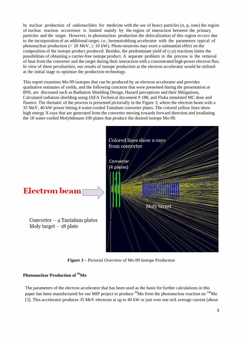
This report examines Mo-99 isotopes that can be produced by an electron accelerator and provides qualitative estimates of yields, and the following concerns that were presented during the presentation at BNL are discussed such as Radiation Shielding Design, Hazard perceptions and their Mitigations, Calculated radiation shielding using IAEA Technical document # 188, and Fluka simulated MC dose and fluence. The thematic of the process is presented pictorially in the Figure 3, where the electron beam with a 35 MeV, 40 kW power hitting 4 water-cooled Tantalum converter plates. The colored yellow lines show high energy X-rays that are generated from the converter moving towards forward direction and irradiating the 18 water-cooled Molybdenum-100 plates that produce the desired isotope Mo-99.
Figure 3 – Pictorial Overview of Mo-99 Isotope Production
Photonuclear Production of 99Mo The parameters of the electron accelerator that has been used as the basis for further calculations in this paper has been manufactured for our MIP project to produce 99Mo from the photonuclear reaction on 100Mo [3]. This accelerator produces 35 MeV electrons at up to 40 kW or just over one mA average current (about

4
7 x 10¹⁵ e/s). Shvetson [6] has developed an effective photon yield equation (1) in the energy window of 8 to 20 MeV which overlaps with much of the photonuclear cross section (especially for heavier nuclei) given by:
Using the value of 0.25 photons per electron (0.22 at 30 MeV from equation-1 and adjusted by the amount calculated in [6] for 35 MeV compared to 30 MeV) in the energy window of 8 to 20 MeV times this quantity of electrons leads to a useful bremsstrahlung yield in the forward direction of about 1.6 x 10¹⁵
photons/s. A large fraction of this will be in a small cone with an area of less than one cm2 at the entrance of the isotope target and 1.5 to 2 cm2 at the exit. This is a very high photon flux and demonstrates why a potentially high isotope yield can be obtained with photonuclear reactions with typical cross sections in the range of 15 to 300 mb. Figure 4 shows the photoneuclear cross section [7] of the 100Mo(γ,n)99Mo reaction, with a threshold of 9 MeV and maximum cross section of 150 mb at 14.5 MeV. These cross sections are generally lower than many of the charged particle cross sections such as (p,n) or (d,n) used to produce isotopes with a cyclotron. However, the cost of producing large quantities of photons is relatively low and the photons can penetrate windows with little power loss making it practical to separate the electron source from a converter target that converts the electrons into bremsstrahlung and further subdivide the isotope target from the converter target with another window. The figure also exhibits the typical Bremsstrahlung photon spectra with 20- and 35-MeV e-beams. The Bremsstrahlung is strongly focused into a forward cone [7] of a few degrees half-width, so some physical spacing between the converter and isotope target is practical.
Figure 4 – Photonuclear x-section of 100Mo and Bremsstrahlung specttra for 20- and 35-MeV electron beam
5
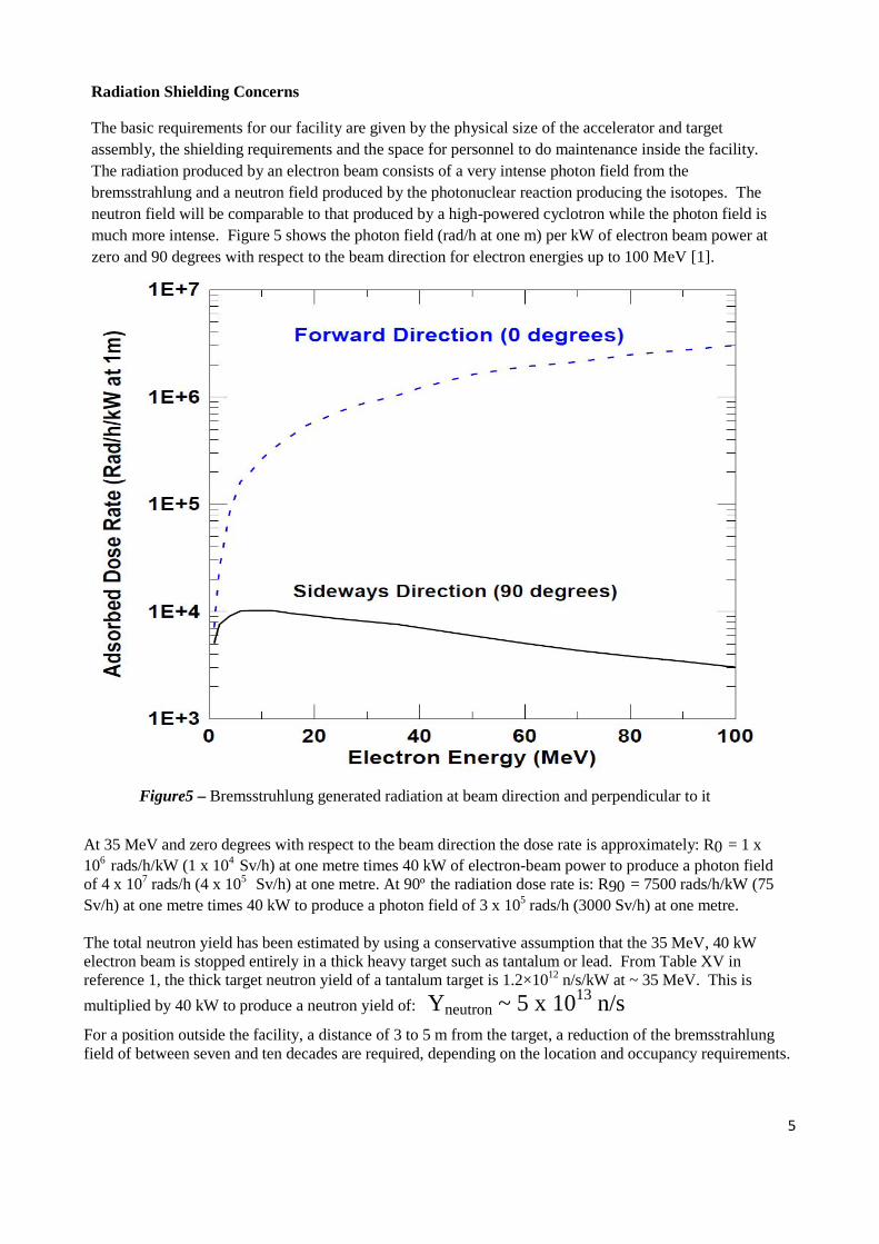
Radiation Shielding Concerns The basic requirements for our facility are given by the physical size of the accelerator and target assembly, the shielding requirements and the space for personnel to do maintenance inside the facility. The radiation produced by an electron beam consists of a very intense photon field from the bremsstrahlung and a neutron field produced by the photonuclear reaction producing the isotopes. The neutron field will be comparable to that produced by a high-powered cyclotron while the photon field is much more intense. Figure 5 shows the photon field (rad/h at one m) per kW of electron beam power at zero and 90 degrees with respect to the beam direction for electron energies up to 100 MeV [1].
Figure5 – Bremsstruhlung generated radiation at beam direction and perpendicular to it
At 35 MeV and zero degrees with respect to the beam direction the dose rate is approximately: R0 = 1 x 10⁶ rads/h/kW (1 x 10⁴ Sv/h) at one metre times 40 kW of electron-beam power to produce a photon field of 4 x 10⁷ rads/h (4 x 10⁵ Sv/h) at one metre. At 90º
the radiation dose rate is: R90 = 7500 rads/h/kW (75
Sv/h) at one metre times 40 kW to produce a photon field of 3 x 10⁵ rads/h (3000 Sv/h) at one metre. The total neutron yield has been estimated by using a conservative assumption that the 35 MeV, 40 kW electron beam is stopped entirely in a thick heavy target such as tantalum or lead. From Table XV in reference 1, the thick target neutron yield of a tantalum target is 1.2×10¹² n/s/kW at ~ 35 MeV. This is multiplied by 40 kW to produce a neutron yield of: Yneutron ~ 5 x 10¹³ n/s
For a position outside the facility, a distance of 3 to 5 m from the target, a reduction of the bremsstrahlung field of between seven and ten decades are required, depending on the location and occupancy requirements.
6
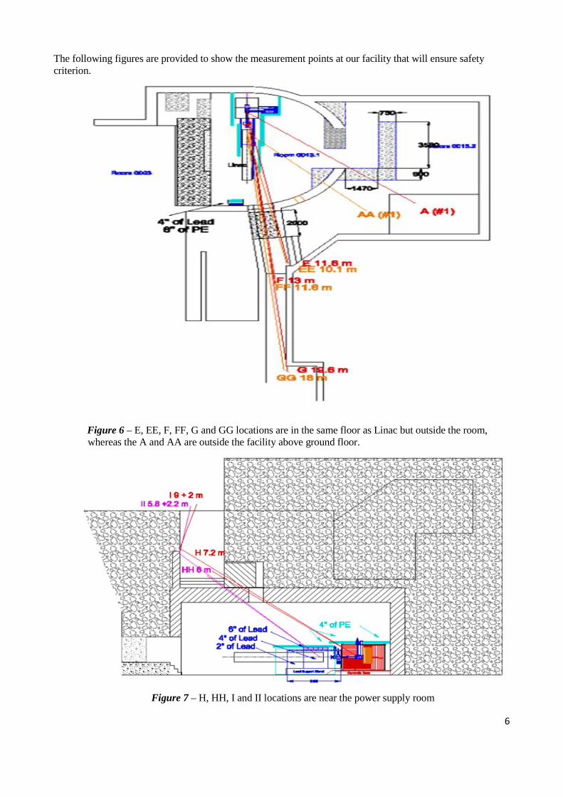
The following figures are provided to show the measurement points at our facility that will ensure safety criterion.
Figure 6 – E, EE, F, FF, G and GG locations are in the same floor as Linac but outside the room, whereas the A and AA are outside the facility above ground floor.
Figure 7 – H, HH, I and II locations are near the power supply room

7
Figure 8 – JJ and KK locations are shown with path length
Figure 9 – J and K locations are shown with path length
8
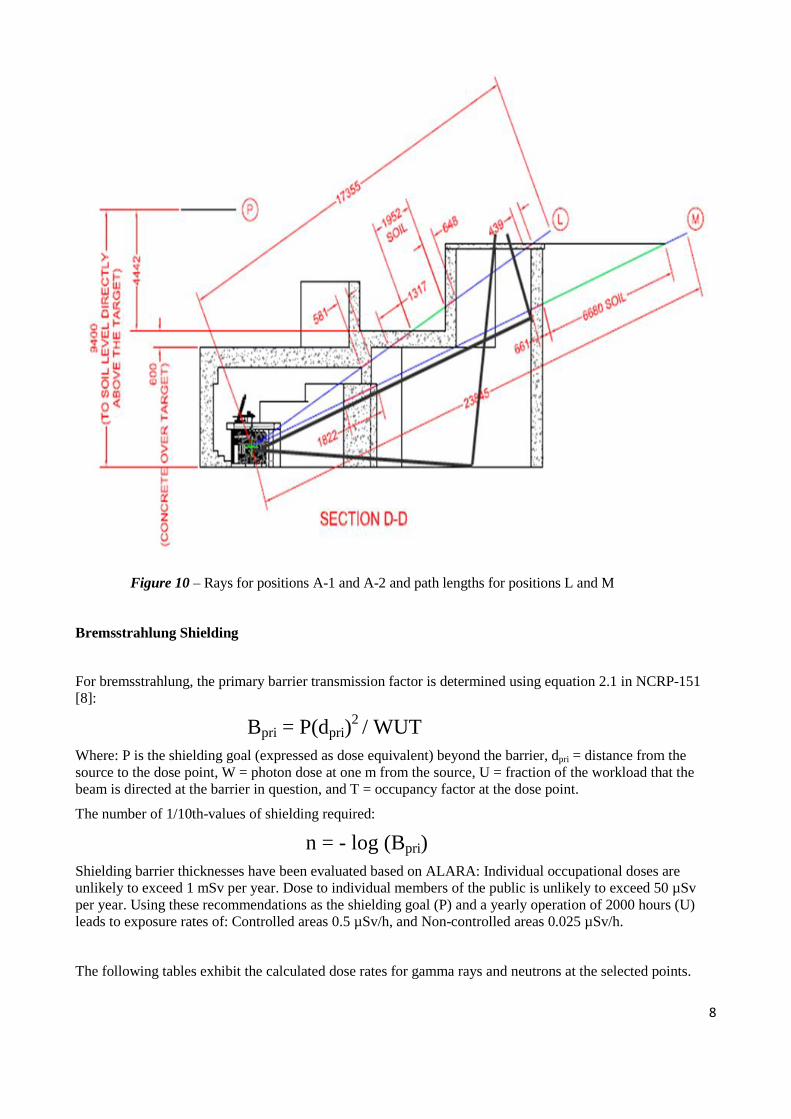
Figure 10 – Rays for positions A-1 and A-2 and path lengths for positions L and M
Bremsstrahlung Shielding
For bremsstrahlung, the primary barrier transmission factor is determined using equation 2.1 in NCRP-151 [8]:
Bpri = P(dpri)2 / WUT Where: P is the shielding goal (expressed as dose equivalent) beyond the barrier, dpri = distance from the source to the dose point, W = photon dose at one m from the source, U = fraction of the workload that the beam is directed at the barrier in question, and T = occupancy factor at the dose point.
The number of 1/10th-values of shielding required:
n = - log (Bpri) Shielding barrier thicknesses have been evaluated based on ALARA: Individual occupational doses are unlikely to exceed 1 mSv per year. Dose to individual members of the public is unlikely to exceed 50 µSv per year. Using these recommendations as the shielding goal (P) and a yearly operation of 2000 hours (U) leads to exposure rates of: Controlled areas 0.5 µSv/h, and Non-controlled areas 0.025 µSv/h.
The following tables exhibit the calculated dose rates for gamma rays and neutrons at the selected points.
9
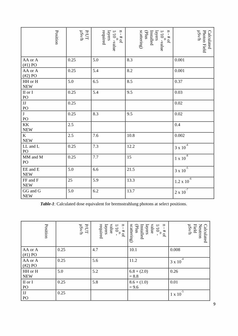
Position
P/UT
µSv/h
n - # of 1/10
th-value layers required
n - # of 1/10
th-value layers Installed (Plus scattering)
Calculated
Photon Field µSv/h
AA or A (#1) PO
0.25 5.0 8.3 0.001
AA or A (#2) PO
0.25 5.4 8.2 0.001
HH or H NEW
5.0 6.5 8.5 0.37
II or I PO
0.25 5.4 9.5 0.03
JJ PO
0.25 0.02
J PO
0.25 8.3 9.5 0.02
KK NEW
2.5 0.4
K NEW
2.5 7.6 10.8 0.002
LL and L PO
0.25 7.3 12.2 3 x 10⁻⁴
MM and M PO
0.25 7.7 15 1 x 10⁻⁸
EE and E NEW
5.0 6.6 21.5 3 x 10⁻⁵
FF and F NEW
25 5.9 13.3 1.2 x 10⁻⁶
GG and G NEW
5.0 6.2 13.7 2 x 10⁻⁷
Table-1: Calculated dose equivalent for bremsstrahlung photons at select positions.
Position
P/UT
µSv/h
n - # of 1/10
th-value layers required
n - # of 1/10
th-value layers Installed (Plus scattering)
Calculated
Neutron
Field µSv/h
AA or A (#1) PO
0.25 4.7 10.1 0.008 AA or A (#2) PO
0.25 5.6 11.2 3 x 10⁻⁴
HH or H NEW
5.0 5.2 6.8 + (2.0) = 8.8
0.26 II or I PO
0.25 5.8 8.6 + (1.0) = 9.6
0.01 JJ PO
0.25 1 x 10⁻⁵
10
J PO
0.25 6.0 8.6 6 x 10⁻⁴
KK NEW
2.5 0.002 K NEW
2.5 5.5 11.4 3 x 10⁻⁷
LL and L PO
0.25 5.5 11.0 1.8 x 10⁻⁶
MM and M PO
0.25 5.3 18.9 - EE and E NEW
5.0 4.6 11.2 2 x 10
-4 FF and F NEW
25 4.1 5.6 0.83 GG and G NEW
5.0 4.3 5.6 0.26
Table-2: Calculated dose equivalent for neutrons at select positions.
Monte Carlo Simulation with Fluka
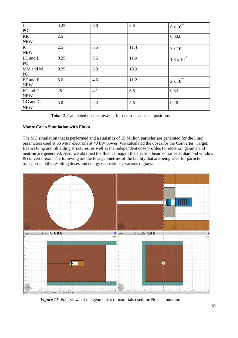
The MC simulation that is performed and a statistics of 15 Million particles are generated for the linac parameters used at 35 MeV electrons at 40 kW power. We calculated the doses for the Converter, Target, Beam Dump and Shielding structures, as well as the independent dose profiles for electron, gamma and neutron are generated. Also, we obtained the fluence map of the electron beam entrance at diamond window & converter exit. The following are the four geometries of the facility that are being used for particle transport and the resulting doses and energy deposition at various regions.
Figure 11: Four views of the geometries of materials used for Fluka simulation
11
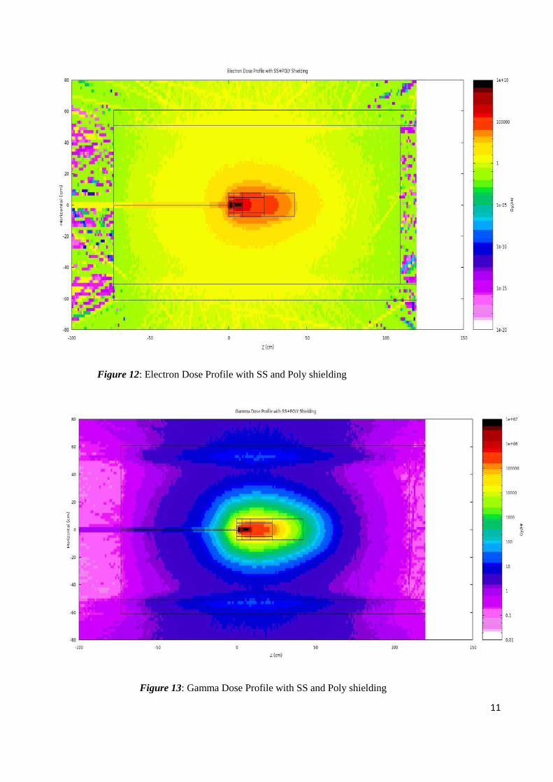
Figure 12: Electron Dose Profile with SS and Poly shielding
Figure 13: Gamma Dose Profile with SS and Poly shielding

12
Figure 14: Neutron Dose Profile with SS and Poly shielding
Figure 15: Beam Dump 2D Energy Deposition
13
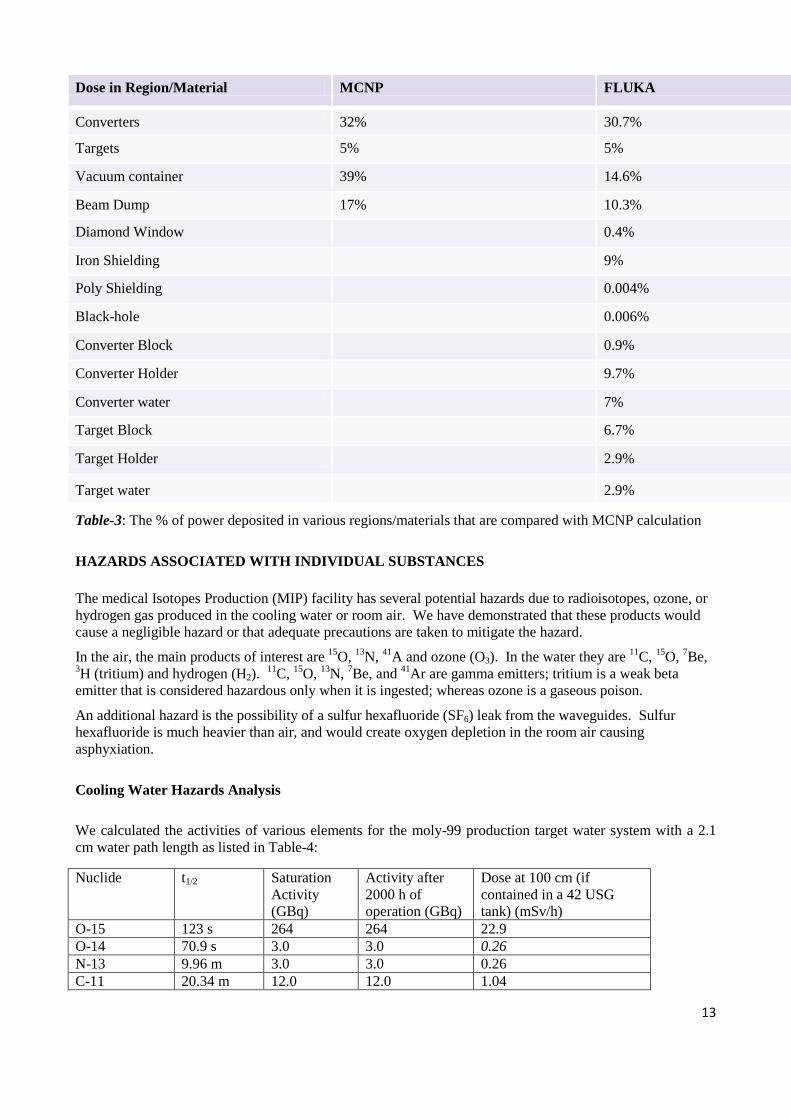
Dose in Region/Material MCNP FLUKA
Converters 32% 30.7%
Targets 5% 5%
Vacuum container 39% 14.6%
Beam Dump 17% 10.3%
Diamond Window 0.4%
Iron Shielding 9%
Poly Shielding 0.004%
Black-hole 0.006%
Converter Block 0.9%
Converter Holder 9.7%
Converter water 7%
Target Block 6.7%
Target Holder 2.9%
Target water 2.9%
Table-3: The % of power deposited in various regions/materials that are compared with MCNP calculation
HAZARDS ASSOCIATED WITH INDIVIDUAL SUBSTANCES
The medical Isotopes Production (MIP) facility has several potential hazards due to radioisotopes, ozone, or hydrogen gas produced in the cooling water or room air. We have demonstrated that these products would cause a negligible hazard or that adequate precautions are taken to mitigate the hazard.
In the air, the main products of interest are 15O, 13N, 41A and ozone (O3). In the water they are 11C, 15O, 7Be, 3H (tritium) and hydrogen (H2). 11C, 15O, 13N, 7Be, and 41Ar are gamma emitters; tritium is a weak beta emitter that is considered hazardous only when it is ingested; whereas ozone is a gaseous poison.
An additional hazard is the possibility of a sulfur hexafluoride (SF6) leak from the waveguides. Sulfur hexafluoride is much heavier than air, and would create oxygen depletion in the room air causing asphyxiation.
Cooling Water Hazards Analysis
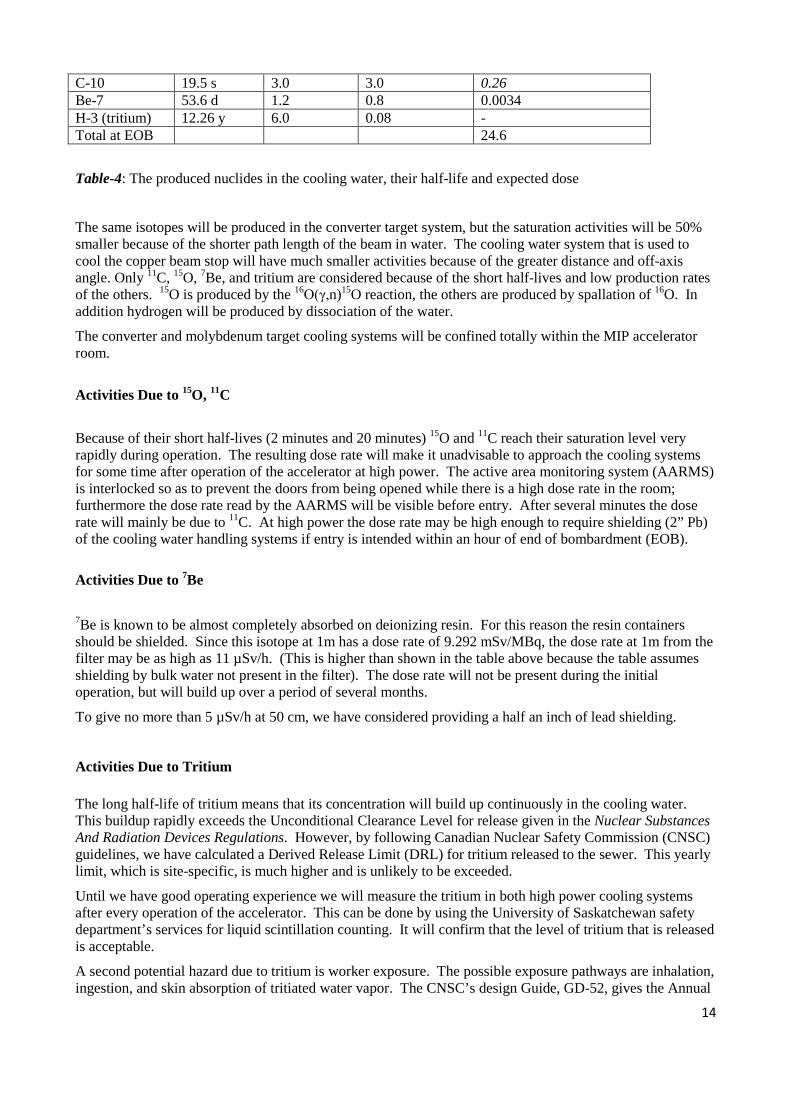
We calculated the activities of various elements for the moly-99 production target water system with a 2.1 cm water path length as listed in Table-4:
Nuclide t1/2 Saturation Activity (GBq)
Activity after 2000 h of operation (GBq)
Dose at 100 cm (if contained in a 42 USG tank) (mSv/h)
O-15 123 s 264 264 22.9 O-14 70.9 s 3.0 3.0 0.26 N-13 9.96 m 3.0 3.0 0.26 C-11 20.34 m 12.0 12.0 1.04
14
Table-4: The produced nuclides in the cooling water, their half-life and expected dose
The same isotopes will be produced in the converter target system, but the saturation activities will be 50% smaller because of the shorter path length of the beam in water. The cooling water system that is used to cool the copper beam stop will have much smaller activities because of the greater distance and off-axis angle. Only 11C, 15O, 7Be, and tritium are considered because of the short half-lives and low production rates of the others. 15O is produced by the 16O(γ,n)15O reaction, the others are produced by spallation of 16O. In addition hydrogen will be produced by dissociation of the water.
The converter and molybdenum target cooling systems will be confined totally within the MIP accelerator room.
Activities Due to 15O, 11C
Because of their short half-lives (2 minutes and 20 minutes) 15O and 11C reach their saturation level very rapidly during operation. The resulting dose rate will make it unadvisable to approach the cooling systems for some time after operation of the accelerator at high power. The active area monitoring system (AARMS) is interlocked so as to prevent the doors from being opened while there is a high dose rate in the room; furthermore the dose rate read by the AARMS will be visible before entry. After several minutes the dose rate will mainly be due to 11C. At high power the dose rate may be high enough to require shielding (2” Pb) of the cooling water handling systems if entry is intended within an hour of end of bombardment (EOB).
Activities Due to 7Be 7Be is known to be almost completely absorbed on deionizing resin. For this reason the resin containers should be shielded. Since this isotope at 1m has a dose rate of 9.292 mSv/MBq, the dose rate at 1m from the filter may be as high as 11 µSv/h. (This is higher than shown in the table above because the table assumes shielding by bulk water not present in the filter). The dose rate will not be present during the initial operation, but will build up over a period of several months.
To give no more than 5 µSv/h at 50 cm, we have considered providing a half an inch of lead shielding.
Activities Due to Tritium
The long half-life of tritium means that its concentration will build up continuously in the cooling water. This buildup rapidly exceeds the Unconditional Clearance Level for release given in the Nuclear Substances And Radiation Devices Regulations. However, by following Canadian Nuclear Safety Commission (CNSC) guidelines, we have calculated a Derived Release Limit (DRL) for tritium released to the sewer. This yearly limit, which is site-specific, is much higher and is unlikely to be exceeded.
Until we have good operating experience we will measure the tritium in both high power cooling systems after every operation of the accelerator. This can be done by using the University of Saskatchewan safety department’s services for liquid scintillation counting. It will confirm that the level of tritium that is released is acceptable.
A second potential hazard due to tritium is worker exposure. The possible exposure pathways are inhalation, ingestion, and skin absorption of tritiated water vapor. The CNSC’s design Guide, GD-52, gives the Annual
C-10 19.5 s 3.0 3.0 0.26 Be-7 53.6 d 1.2 0.8 0.0034 H-3 (tritium) 12.26 y 6.0 0.08 - Total at EOB 24.6
15
limit of Intake (ALI) for tritium as 109 Bq. After a year’s operation the tritium concentration in cooling water is expected to be less than 103 Bq/ml, making it improbable that a person will absorb as much as 1% of ALI. Nevertheless, for ALARA purposes, plastic or rubber gloves would be worn by any person who could come in contact with the cooling water. In addition, the cooling systems will be flushed before any disassembly.
Production of Hydrogen by Water Radiolysis
Hydrogen gas will be produced by radiolysis of cooling water in the converter and target. At the full design power of 40 kW at 35 MeV we estimated that 212 liters/day (about 9 liter/h) would be produced in the converter with a considerably lesser amount produced in the production target. An air separator in each of the cooling water circuit will lead this evolved gas into the ventilation exhaust.
The room ventilation, 700 cfm, is adequate to ensure that the hydrogen concentration is never above 1% in the room air or in the exhaust and therefore explosion-proof construction is unnecessary according to section 4.1.7 of the National Fire Code referencing NFPA 91. Nevertheless, the exhaust fan itself is explosion-proof.
Redundant hydrogen sensors will be placed at the highest point in the room and in the ventilation exhaust in order to continuously demonstrate that the concentration is as low as assumed. An alarm will sound if the concentration reaches 0.8%.
The size of the room is such that it would take several days without ventilation for the concentration to reach 1%. Nevertheless, in case of ventilation fan failure, the accelerator and the cooling water pumps are both stopped (although by a system that is not safety rated), preventing further release of hydrogen to the room or to the ventilation duct.
Hazardous Gases Released to Room Air
A number of gasses can cause hazards when released into the room. These include radioactive, poisonous and asphyxiation hazards.
Activities Due to 15O & 13N
15O & 13N are produced by the x-ray beam passing through air. For a 35 MeV electron beam producing the x-rays, this is only true for beam within 30° of the axis. As long as the air gap in the forward direction is kept low, the concentrations of these isotopes will not exceed safe limits.
Activities Due to 41Ar 41Ar is produced by the (n,γ) reaction with the argon that is naturally present in the room air. The neutron yield from the converter and production targets totals about 5 x 10¹³ n/s into 4 . Most of these neutrons are absorbed in the iron shielding surrounding the converter and target, but there are four stems penetrating the shielding. Only the stem facing the converter need be considered – this 130 cm path length produces < 0.1 MPC (maximum permissible concentration) of 41Ar.
Effect of Leakage of SF6
We have a stock of (before filling the waveguides) four cylinders, each with 115 lb. of SF6 gas. SF6 is a very dense gas and can be expected to displace air starting at the floor. While a severe leak that could lead to
16
large amounts of SF6 in the room air is unlikely (especially in the presence of ventilation), an oxygen detector will give assurance that the area is safe.
Ozone Production
Ozone is produced by the interaction of x-rays from the converter target with air. In addition to ozone, other materials are formed in air such as nitrogen oxide, which may react with ozone to form nitrogen dioxide (NO2), which subsequently reacts with water vapor in air to form nitric acid (HNO3). Because of its low Threshold Limit Value of 0.1 ppm for occupational exposure conditions (8 hours per day, 40 hours per week) and its high production rate compared to NO2 and HNO3, ozone is the most important of the noxious products. Other oxides of nitrogen (NOX) may also be formed but are of lesser importance.
Ozone is chemically active and decomposes spontaneously with a chemical half-life of approximately 50 minutes. Ozone can harm lung function and irritate the respiratory system in humans. Ozone produces a distinctive smell and is immediately noticeable in fairly small concentrations.
Ozone will be produced in areas where air is exposed to the highest dose rates. Since this production is a chemical, not nuclear phenomenon, it will take place off-axis also, particularly in the voids in the target shielding which allow entry of the beam pipe and the target servicing stems.
Ozone production in the air outside the target shielding block will be low because the dose rates are fairly low. The production in shielding voids will also be low because the voids are small.
Ventilation to Reduce Hazard
The linac room will be ventilated with an exhaust fan at the rate of 700 ft3 min-1. 13N is the dominant gaseous radioisotope produced by the (γ,n) reaction. The concentration of the 13N will be 1.1 x 10⁻³ Bq/cm3, which is below the MPC (maximum permissible concentration) of 0.074 Bq/cm3.
Argon activation from neutrons streaming out the shielding void in place for the converter target support is estimated to give a concentration of 0.014 Bq/cm3 for ventilation of 700 ft3 min-1, where the MPC is 0.2 Bq/cm3.
The total ozone production in the room including the shielding void spaces inside is conservatively estimated to be 1.4 x 10⁻⁸. This is well below the allowable concentration (threshold limit value) of 10-7.
References [1] Radiological safety aspects of the Operation of Electron Linear Accelerators, International Atomic
Energy Agency Technical Report Series # 188, Vienna (1977). [2] G.T., Herman, “Image Reconstruction from Projections: The Fundamentals of Computerized
Tomography”, New York, Academic Press (1980). [3] M.S. de Jong, “Producing Medical Isotopes Using X-rays”, CLS, Saskatoon, IPAC 2012
(International Particle Accelerator Conference) in New Orleans (2012). [4] N.P. Dikiy, A.N. Dovbnya, S.V. Maryokhin and V.L. Uvarov, Problems of Atomic Science
and Technology. Series: “Nuclear Physics Investigations” 34 (1999) 91. [5] R.G. Bennet et al., Nuclear Technology 126 (1999) 102. [6] V. N. Shvetsov,1 E. I. Sharapov,1 S.L. Stephenson, and B.E. Crawford, “Comparison of Calculated
and Measured Yields of Medical Isotopes Produced by Electron Bremsstrahlung”,16th International Seminar on Interaction of Neutrons with Nuclei: Fundamental Interactions & Neutrons, Nuclear Structure, Ultracold Neutrons, Related Topics, ISINN-16, Dubna, Russia, June 11-14 (2008).
[7] IAEA Tecdoc 1178, “Handbook on Photonuclear Data for Applications, Cross Sections and Spectra”, International Atomic Energy Agency, Vienna, October (2000).
[8] NCRP Report 151 “Structural shielding design and evaluation for megavoltage x-and gamma-ray radiotherapy facilities” J. Radiol. Prot. 26 (2006) 349.