radio technologies passanger...
TRANSCRIPT

2017. október 9.,
Budapest
RADIO TECHNOLOGIES ON AIRCRAFTS
PASSENGER AIRCRAFT- UAV
Dr. István Koller
Department of Networked Systems and
Services
Budapest University of Technology
and Economics
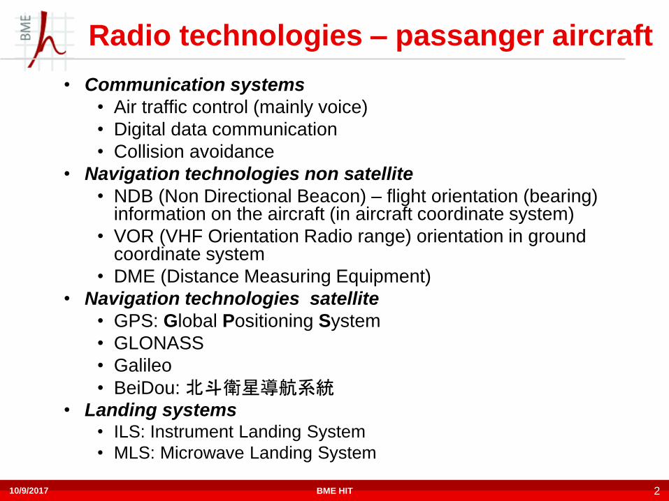
Radio technologies – passanger aircraft
• Communication systems
• Air traffic control (mainly voice)
• Digital data communication
• Collision avoidance
• Navigation technologies non satellite
• NDB (Non Directional Beacon) – flight orientation (bearing)information on the aircraft (in aircraft coordinate system)
• VOR (VHF Orientation Radio range) orientation in ground coordinate system
• DME (Distance Measuring Equipment)
• Navigation technologies satellite
• GPS: Global Positioning System
• GLONASS
• Galileo
• BeiDou: 北斗衛星導航系統• Landing systems
• ILS: Instrument Landing System
• MLS: Microwave Landing System
10/9/2017 BME HIT 2

Radio Communication bands used
in aviation
MF: 0.3-3MHz (wavelength: 1000m-100m)
HF: 3-30MHz (wavelength: 100m-10m)
VHF: 30-300MHz (10m-1m)
UHF: 300-3000MHz ( 1m -1dm)
SHF: 3GHz-30GHz (1dm - 1cm)
10/9/2017 3BME HIT

Communication – voice
Voice communication (telephony)
• 118-137MHz (aeronautical VHF band)
• Analog Amplitude Modulation,
• ~3 kHz baseband,~ 6kHz RF RF bandwidth
• 8.33 kHz channels (25/3kHz)
• 1,5-30 MHz: rarely used
• SSB (single side band) AM
• Primary role: air traffic control
• Digital voice communication standard has never became
widespread, however it exists in VDL (ICAO International
Civilian Aviation Organization VHF Data Link) Mode 3 (118-
137MHz)
10/9/2017 BME HIT 4

Communication – digital data
Data communication between ground-air stations
• ACARS: Aircraft Communications Addressing and Reporting System, since 1978
• 118-137 MHz: MSK or ICAO VDL Mode 2 (VHF Data Link)
• 3-30 MHz: HFDL (High Frequency Data Link)
• AMSS: Aeronautical Mobile Satellite System
– IRIDIUM, INMARSAT
• CPDLC: Controller-Pilot Data Link Communication
• 2 major implementations:
– FANS-1/A (Future Air Navigation System): developed by Boeing and Airbus, deployed in North-Atlantic and South Pacific routes
– Eurocontrol’s system in many European Flight Information Regions
• 118-137MHz: ICAO VDL Mode 2
• AMSS Aeronautical Mobile Satellite System
– IRIDIUM, INMARSAT
10/9/2017 BME HIT 5

Communication – digital data
Data communication between ground-air stations (cont’d.)
• ADS-B: Automatic Dependent Surveillance – Broadcast
• ADS-C: Automatic Dependent Surveillance – Contract
• Both use SSR transponders on 1090MHz (USA: 978MHz too)
Data communication between air-air stations
• TCAS/ACAS: Traffic/Airborne Collision Avoidance System
• Based on SSR transponders (see later)
Special communication need: Emergency
Emergency frequencies - Emergency Locator Transmitter
(ELT)
• 121,5MHz, 243MHz Analog frequencies are NOT monitored
by Satellite sysetems
• 406MHz new Satellite monitored digital systems
10/9/2017 BME HIT 6

ACARS PHY
Created in 1978
VHF (118-137MHz ) system (aeronautical VHF band)
• MSK: 1200 and 2400Hz tones, 2.4kbps, amplitude modulated
carrier
• VDL Mode 2: 8PSK, 10500 symbols/s, gross bitrate: 31.5kbps
HF (3-30 MHz) system
• HFDL: 1800 symbols/s, BPSK, QPSK or 8PSK, with different
FEC
• 300, 600, 1200 or 1800 bps speed
• Used where VHF coverage is not present
• Global coverage with 17 ground stations operating on 145
frequencies
10/9/2017 BME HIT 7

ACARS HFDL Coverage
10/9/2017 BME HIT 8
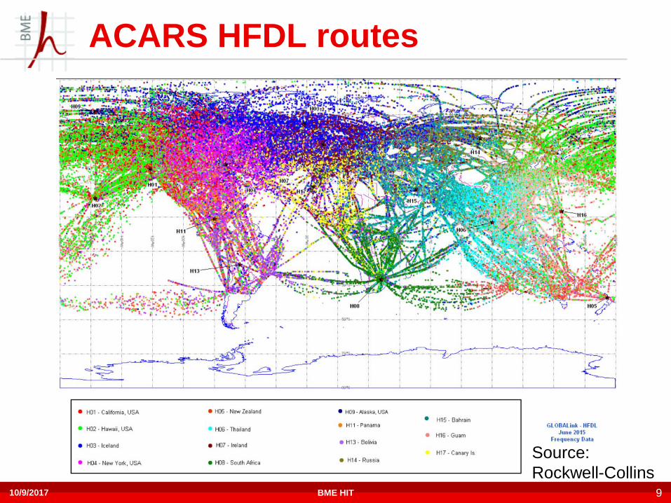
ACARS HFDL routes
Source:
Rockwell-Collins10/9/2017 BME HIT 9

ACARS Usage Main message types:
• Air Traffic Control – Pilot communication
• Aeronautical Operational Control
• Airline Administrative Control
Examples:
• OOOI: Out of gate, Off the ground, On the ground, Into the gate
• FMS (Flight Management System) Interface: updating flight plans
• Engine status reports
• Position data
• E-mail like communication between the flight crew and the ground stations (clearances, information requests, connecting flights)
• NOT optimal for fast air traffic control, because of the possible long delay!
10/9/2017 BME HIT 10

CPDLC usage
Classical Controller-Pilot: voice
Controller - Pilot Data Link Communication: text
• Data link between Air Traffic Controller and pilot
• Alternative to voice communication in busy airspaces
• Messages are displayed on the flight deck
• Standard (clearance, information, request) messages and
free text
• Eg. Runway cleared, request altitude, speed, etc.
• No worldwide deployment yet
• FL380 – Flight level: 38 000 Feet
10/9/2017 BME HIT 11

ICAO VDL mode2 ACARS, CPDLC,
GBAS 118.. 137MHz (aeronautical VHF band) 25 kHz bandwith,
channel spacing
D8PSK 10500 symbol/s, 31.5 kbit/s modulation
Half duplex – communication on the same frequency for
uplink, downlink
Common Signaling Channel: 136.975 MHz for initial link
establishment
Media access: CSMA
10/9/2017 12BME HIT
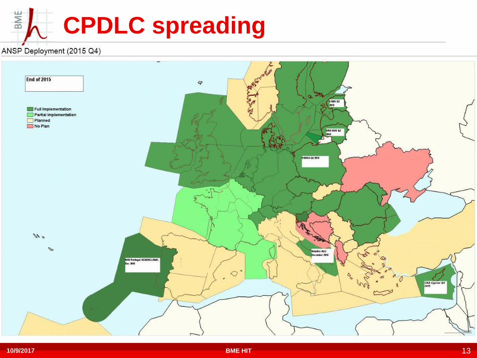
CPDLC spreading
10/9/2017 BME HIT 13

Cockpit of 787 DreamlinerInstructions from the controller can be accepted, rejected or
cancelled by the pilot, altitude, speed, heading, etc. values can be
transferred in the appropriate windows by XFR buttons
Messages are displayed in the AUX
window
10/9/2017 BME HIT 14
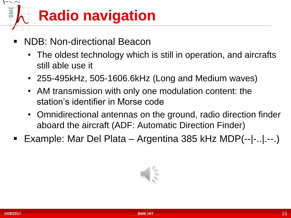
Radio navigation
NDB: Non-directional Beacon
• The oldest technology which is still in operation, and aircrafts
still able use it
• 255-495kHz, 505-1606.6kHz (Long and Medium waves)
• AM transmission with only one modulation content: the
station’s identifier in Morse code
• Omnidirectional antennas on the ground, radio direction finder
aboard the aircraft (ADF: Automatic Direction Finder)
Example: Mar Del Plata – Argentina 385 kHz MDP(--|-..|.--.)
10/9/2017 BME HIT 15
(-- -.. .--.)

Radio navigation
VOR: VHF Omnidirectional Radio Range
• 108-118 MHz
• Basically AM signal
• Identifier in Morse code (sometimes in telephony)
• FM subcarrier containing a reference signal (30Hz)
• AM subcarrier transmitted by a directional antenna containing
the navigation signal (30Hz)
• The phase of the navigation signal is depending on the position
of the reception
• The phase difference between the two signals is the bearing
• Direction finding is not necessary on the aircraft!
• More accurate than NDB, however its range is shorter
10/9/2017 BME HIT 16

VOR operation
𝑟 𝑡 = cos(𝜔𝑐𝑡)(1 + 𝑐 𝑡 + 𝑔 𝐴, 𝑡 )
𝑐 𝑡 = Xid(t) + 0.3cos 0
𝑡
𝜔𝑠 + 𝜔𝑑 cos 𝜔𝑛𝜏 𝑑𝜏
Consider the signal at the receiver at azimuth angle A:
where
𝑔 𝐴, 𝑡 = 0.3 cos(𝜔𝑛𝑡 − 𝐴)
𝜔𝑐 is the carrier angular frequency
𝑋𝑖𝑑 𝑡 is the identifier baseband signal (Morse code + voice)
𝜔𝑠 is the subcarrier angular frequency 2𝜋 ⋅ 9960𝐻𝑧𝜔𝑑 is the subcarrier deviation 2𝜋 ⋅ 480𝐻𝑧𝜔𝑛 is the navigation tone angular frequency 2𝜋 ⋅ 30𝐻𝑧Note that 𝑐 𝑡 is independent from the azimuth angle 𝑔 𝐴, 𝑡 is dependent!
The VOR receiver demodulates the reference signal (FM) and compares the
phase of the navigation signal with the reference. The phase difference between
the two is the bearing.
AVOR
TX
Aircraft
10/9/2017 BME HIT 17

VOR receiver block diagram
10/9/2017 18BME HIT
108.. 118MHz
𝑟 𝑡 = cos(𝜔𝑐𝑡)(1 + 𝑐 𝑡 + 𝑔 𝐴, 𝑡 ) 𝑐 𝑡 = Xid(t) + 0.3cos 0
𝑡
𝜔𝑠 + 𝜔𝑑 cos 𝜔𝑛𝜏 𝑑𝜏
𝑔 𝐴, 𝑡 = 0.3 cos(𝜔𝑛𝑡 − 𝐴)
NDB vs. VOR
AVOR
TX
Aircraft
ANDB
TX
Aircraft
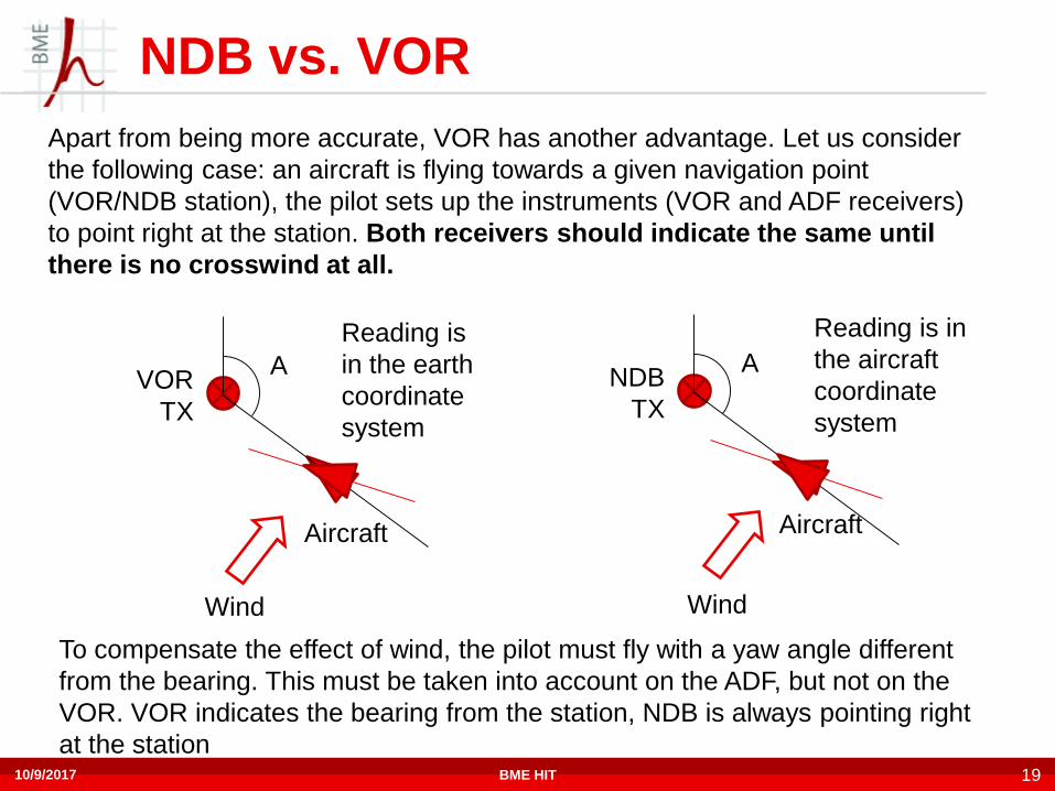
Apart from being more accurate, VOR has another advantage. Let us consider
the following case: an aircraft is flying towards a given navigation point
(VOR/NDB station), the pilot sets up the instruments (VOR and ADF receivers)
to point right at the station. Both receivers should indicate the same until
there is no crosswind at all.
Wind Wind
To compensate the effect of wind, the pilot must fly with a yaw angle different
from the bearing. This must be taken into account on the ADF, but not on the
VOR. VOR indicates the bearing from the station, NDB is always pointing right
at the station
Reading is
in the earth
coordinate
system
Reading is in
the aircraft
coordinate
system
10/9/2017 BME HIT 19

Radio navigation
DME: Distance Measuring Equipment
• The aircraft can measure the distance from a given station
• The ground speed can also be estimated from the doppler
shift (if flying straight to or from a station)
• Typically deployed together with VOR stations
• Interrogator (aircraft): 1025-1150MHz
• Transponder (ground station): (interrogator +-63MHz ) 962-
1213MHz – 50us delay
• 126 pcs. of 1MHz channels
• Accuracy: app. +-0.1NM (+-180m)
10/9/2017 BME HIT 20
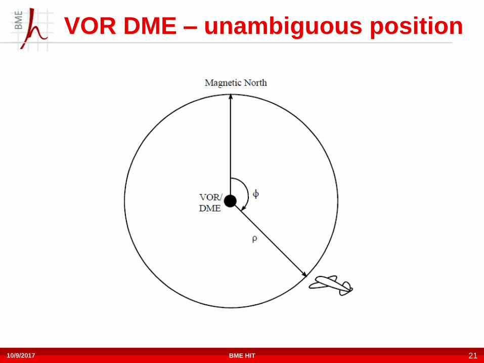
VOR DME – unambiguous position
10/9/2017 21BME HIT

Pusztaszabolcs VOR, NDB
From: Kállai Tibor (Panoramio)
NDB
antenna
(386kHz)
VOR
antenna
(117.1MHz)
DME
antenna
10/9/2017 BME HIT 22

Pusztaszabolcs VOR
From: Kállai Tibor (Panoramio)
10/9/2017 BME HIT 23

Radio navigation - landing
ILS: Instrument Landing System
• Localizer
• 108,1-111,95MHz
• Indicates the deviation from the runway centerline
• Based on a phased array
• Glideslope
• 330,95-334,7 MHz, paired with localizer frequencies
• Indicates the deviation from the ideal glideslope
• Based on a phased array
• The stations transmit AM signals, and the localizers identify themselves with Morse code
MLS: Microwave Landing System
• Never became widespread, due to advanced GNSS technologies (with GBAS)
10/9/2017 BME HIT 24

Radionavigation – Landing
Localizer
phased
array
Glideslope
phased
array
Glideslope
phased
array
The green lobe is a carrier modulated with
90Hz, the blue lobe is the same carrier
modulated with 150Hz.
When the plane is flying on the desired path
(runway centerline and descending with the
desired rate) all signals will have the same
amplitude.
If the plane deviates from the path, the signal
which is stronger in that direction will have
larger amplitude, and this can be indicated.
10/9/2017 BME HIT 25

Phase array
10/9/2017 26BME HIT

ILS receiver
10/9/2017 27BME HIT

Hannover Airport Localizer
Source: Wikipedia
10/9/2017 BME HIT 28

Hannover Airport Glideslope
Source: Wikipedia
10/9/2017 BME HIT 29

ILS on the headup display
10/9/2017 30BME HIT

Budapest Airport
VOR/DME
117,3
„BUD”NDB
357kHz
„L”
LOC
109,5
„BPR”
GP/DME
SSR
10/9/2017 BME HIT 31

Airport Surveillance Radar (ASR)
systems
Primary Surveillance Radar - PSR (2700.. 2900MHz)
• Detects targets (aircraft) based on the reflected waves
• Capable of detecting targets, and can measure the speed
• The range is limited by the effective radiated power density
and the effective radar cross section of the target
Secondary Surveillance Radar -SSR (1030MHz, 1090MHz)
• A transmitter-receiver (transponder) is necessary aboard the
aircraft, which responds to interrogation requests
• The transponder can also transmit data (identifier, altitude,
speed, etc.)
• The power of the transponder is orders of magnitude greater
than the reflected power, therefore the range can be
considerably longer
10/9/2017 BME HIT 32
SSR Transponder
Common system for military a civilian aircraft
Originating from IFF (Identification Friend or Foe, World
War II)
5+1 modes of operation for military aircraft, 3 modes for
civilian
ADS-B is based on Mode-S transponders, but it is
transmitted without interrogation
Interrogation frequency 1030MHz, transmission frequency
1090 MHz
The peak pulse power available at the antenna end of the
transmission line of the transponder shall be at least 21 dB
and not more than 27 dB above 1 W
10/9/2017 BME HIT 33
SSR Transponder Modes
Military
Mode
Civilian
ModeDescription
1 Provides 2-digit 5-bit mission code (cockpit selectable)
2Provides 4-digit octal unit code (set on ground for fighters, can be
changed in flight by transport aircraft)
3 AProvides a 4-digit octal identification code for the aircraft, set in the
cockpit but assigned by the air traffic controller.
3 CProvides the aircraft's pressure altitude in 4-digit octal code (Gilham
Code)
4 Provides a 3-pulse reply, delay is based on the encrypted challenge
5Provides a cryptographically secured version of Mode S and ADS-B
GPS position
S SProvides multiple information formats to a selective interrogation.
Each aircraft is assigned a fixed 24-bit address.
10/9/2017 BME HIT 34

SSR Transponder Operation
Interrogation, on 1030MHz radiated by ground station radar:
• P2 pulse is the sidelobe suppression pulse, transmitted by an
omnidirectional antenna with at least the same power as the strongest
sidelobe.
• Aircraft in the main lobe will receive P1 stronger than P2, while aircraft in the
sidelobe will receive P2 as strong as (or even stronger than) P1.
• If P1 is not stronger than P2, the transponder will not answer
10/9/2017 BME HIT 35

SSR Transponder Operation
Response on 1090MHz
• The modulation is PAM (Pulse Amplitude Modulation): no pulse = 0, pulse = 1
• The response contains 2 framing pulses (F1, F2) and 12 data bits, which
correspond to a 4 digit octal value, meaning either altitude or identification
code (squawk code). The SPI (Special Purpose Identification) pulse is the
„IDENT” pulse, which can be transmitted upon pilot request. Pulse X is
reserved
10/9/2017 BME HIT 36

SSR Transponder Response Example
Mode A or C
response from a
passing airplane
captured at the
University
A4, A2, A1: 000 = 0
B: 101 = 5
C: 110 = 4
D: 000 = 0
Octal Code: 0540
F. e.:
7700 means general
emergency as A
7700 means 20 000
feat altitude as C
(7700 can easily be
detected)
10/9/2017 BME HIT 37

Mode A, Mode C summary
10/9/2017 38BME HIT

Mode S SSR
10/9/2017 39BME HIT
Mode S is an enhanced SSR technology from A and C
S mode transponders can de addressed by a unique 24 bit
address, which is assigned to the aircraft itself ( better info
than Mode A answer)
Can send information f. e.:
• aircraft type and aircraft ID
• altitude,
• latitude,
• longitude
• airborne velocity…

Mode S
How do we discover Mode S capable aircraft?
• Mode S transponders use a fixed 24 bit unique address
• Mode A uses 12 bit address assigned by the ATC
A Mode S All Call interrogation is necessary, which tells Mode S
capable transponders to respond with their unique 24 bit address
This pulse must not confuse A or C interrogations
The solution is the use of P4 (1.6us long) pulse, which is discarded by
non-mode S transponders
10/9/2017 BME HIT 40
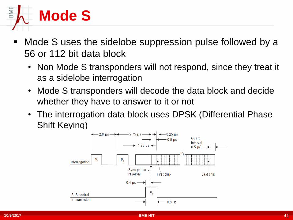
Mode S
Mode S uses the sidelobe suppression pulse followed by a
56 or 112 bit data block
• Non Mode S transponders will not respond, since they treat it
as a sidelobe interrogation
• Mode S transponders will decode the data block and decide
whether they have to answer to it or not
• The interrogation data block uses DPSK (Differential Phase
Shift Keying)
10/9/2017 BME HIT 41

Mode S
Mode S responses contain a 2x2 pulses as preamble
followed by 56 or 112 bit data block
The data block uses PPM (Pulse Position Modulation)
10/9/2017 BME HIT 42

Mode S
-30 dBm
-40 dBm
-50 dBm
-60 dBm
-70 dBm
-80 dBm
-90 dBm
-100 dBm
-110 dBm
M1[1] -61.73 dBm
6.000000000 µs
D2[1] 0.00 dB
0.000000000 s
Att 0 dB
*
*
*
RBW
VBW
SWT
3 MHz
10 MHz
40µs
1Pk
Clrw
Ref -20.00 dBm
Trg
IFP
4.0 µs/CF 1.09 GHz
SGL
M1D2
Date: 31.AUG.2017 17:14:46
Beginning of a Mode S
transponder response
10/9/2017 BME HIT 43

Mode S Downlink Frames
DF
5 bits
Data block
27 or 83 bits
Parity
24 bits
56 or 112 bits
Data Format - DF field defines the downlink frame format
The parity field is generated from the DF and data block
10/9/2017 BME HIT 44

TCAS
Traffic Collision Avoidance System
Based on SSR transponders
The interrogation signal is sent by the airplane
Aircraft equipped with TCAS can detect nearby airplanes
• Informs the pilot about traffic (Traffic Advisory) if the intruder
is within 3.3NM, ±850ft up or down
• Issues a Resolution Advisory if the intruder is within 2.1NM
±600ft up or down: Instruction to the pilots:fly higher alt or
lower alt
TCAS-2 allows the use of Mode S, which provides
significantly more information - world wide used now
10/9/2017 BME HIT 45

ADS-B
Automatic Dependent Surveillance – Broadcast
• Automatic: needs no operator input, nor interrogation
• Dependent: depends on the aircraft’s navigation system
• Based on SSR transponders (1090MHz S mode)
• Transmissions are not requested -> broadcast
• ADS-B messages are always 112 bit long, contains info:
• Identification (24 bit aircraft address, aircraft identification)
• Altitude (barometric),
• Heading,
• Speed,
• Position (latitude, longitude)
• …
10/9/2017 BME HIT 46

ADS-B summary
Aircraft determines position
using GPS
Broadcasts position, identity,
altitude and velocity (ADS-B
out)
Ground stations and
satellites receive, broadcasts
and relay information to ATC
Other aircraft receive
broadcasts & display to pilot
(ADS-B in)
10/9/2017 47BME HIT
ADS-C (Also known ADS-A)
Automatic Dependent Surveillance – Contract (Addressed)
• Similar data as in ADS-B, but for a specific ground control station
• The ground station agrees with the aircraft upon
• The data content of the messages
• Events triggering reports
• Contract types:
• Periodic Contract
• Demand Contract
• Event contract
– Waypoint change event (when passing a waypoint and heading for a new one)
– Level range deviation event
– Lateral deviation event
– Vertical rate change deviation event
10/9/2017 BME HIT 48

Radio navigation – Satellite Based
GNSS: Global Navigation Satellite System
• GPS: Global Positioning System
• US system
• Project launched in 1973, fully operational since 1995
• Full global coverage
• GLONASS: Глобальная навигационная спутниковая
система
• Russian system
• Launched in 1976, completed in 1995
• Full global coverage since 2010
10/9/2017 BME HIT 49

Radio navigation – Satellite Based
• Galileo
• EU system
• Launched in 2005, Early Operational Capability since 15.
December 2016., full operation: ~2019
• BeiDou: 北斗衛星導航系統
• Chinese system
• Launched in 2000
• Covering China, India, Indonesia, Philippines, Australia since
2012
• Expected to provide global coverage in 2020
10/9/2017 BME HIT 50

GNSS Basics
Satellites orbiting the Earth contain atomic clocks, therefore
every satellite can transmit data with the exact* same
timing
Radiovawes travel with the same* speed
Each satellites’ signal will arrive to the receiver with
different timing
The receiver can decode the data coming from the
satellites, and determine the time difference of arrival of
each satellites’ signal
Satellites broadcast their exact* position (Almanac data)
From the time difference and the satellite almanac data, the
receiver position can be calculated
The problems are due to the *-ed items
10/9/2017 BME HIT 51

GNSS Basics
Atomic clocks are very-very precise devices, but they still
drift away
Speed of light: 299 792 458 m/s in vacuum
• Earth has atmosphere, waves must penetrate this, and the
speed of light is not exactly the same as in vacuum
• 1ns temporal error corresponds to ~30cm spatial error
GNSS satellites deviate from their desired orbit
A ground control segment is necessary
• Verify the integrity of the navigation data
• Make adjustments, and corrections if necessary
The achievable accuracy with these measures, is in the
order of 10 meters
10/9/2017 BME HIT 52
GNSS Augmentation
The accuracy of satellite based navigation can be improved by augmenting satellite data
The positions of well known ground stations are measured, and from the error, augmentation data can be derived and sent to the receiver
The data can be sent in two ways:• Satellite Based Augmentation System (SBAS)
• WAAS (Wide Area Augmentation System) in USA
• EGNOS (European Geostationary Navigation Overlay Service) in Europe
– Precision: ~3m
– 3 Geostationary satellites transmits the augmentation data
– GPS, GLONASS, GALILEO
• Ground Based Augmentation System (GBAS)• Augmentation data is transmitted in VHF band in the vicinity of the
airport (108.. 118MHz, 25 kHz Bandwith D8PSK)
• Can be used for precision approach (instead of ILS)
• Precision: ~1m
10/9/2017 BME HIT 53

SBAS Systems
Source: Wikipedia
10/9/2017 BME HIT 54
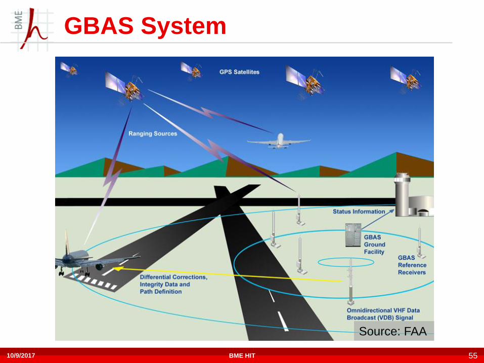
GBAS System
Source: FAA
10/9/2017 BME HIT 55

GPS system frequencies
10/9/2017 56BME HIT

Radio antennas on a passanger aircraft
10/9/2017 57BME HIT

Cockpit of 787 Dreamliner
Communication
and navigation
radio panels
Transponder
control
10/9/2017 58Department of Networked Systems and Services BUTE

Digital data communication between the GCS and UAV
• Control
• Telemetry
• Payload
Navigation
• GNSS ~15 m - outdoor
• SBAS - EGNOS ~3m
• GBAS - RTK ˇ~1dm
• Based on UWB technology – indoor 1dm
Collision Avoidance
• ADS-B
• FAA: below 5,500 m use the 978MHz instead of 1090MHz
• Receiver
• Transmitter
Dr. Istvan Koller
AMOR
ES
59
Department of Networked Systems and Services BUTE
UAV radio electronic systems

Typical UAV mission
UAV flies autonomously
• Flight plane uploaded on the
ground
• Auto takeoff – or manual
• Autonomous flight according
to the plan
• Autolanding – or manual
During operation
• Continuous supervision of
the UAV
• GCS
– Radio link
Dr. Istvan Koller
AMOR
ES
60
Department of Networked Systems and Services BUTE

UAV Digital Data Communication
No global standards
• No standardized frequency bands in Europe for UAVs
• China has: 840.5 – 845MHz, 1430-1444MHz, 2408 – 2440MHz (ISM)
Communication solutions nowadays
• Cellular solutions
• 2G GPRS, EDGE – can be used for telemetry
• 3G, 4G LTE can be used for f.e. video stream too
• Telecom Satellite solution
• L1 Iridium
• Custom radio solutions operating
• ISM bands
• Hired bands
• WiFi solutions (ISM band)
• 2.4GHz Band
• 5.8GHz Band
10/9/2017 61BME HIT
Connection the GCS – UAV
MAVLINK protocol for Telemetry/control
MAVLINK (Micro Aerial Vehicle Link) protocol
• Standard protocol between the GCS and
autopilot
• Can be used
• Send commands to the UAV
• Receive telemetry and other data from the
autopilot
62BME HITDr. Koller István

63BME HITDr. Koller István

Public Cellular Service
The UAV can be sent very far away equipped by cellular
communication modem
Moving Cellular modems at high altitude: potential UAVs
• G2
• 900MHz
• 1800MHz
• G3
• 2100MHz
• G4 LTE
• 800MHz
• 1800MHz
• 2600MHz
64Dr. Koller István Department of Networked Systems and Services BUTE

2G coverage of Hungary by
Hungarian Telekom
65Department of Networked Systems and Services BUTEDr. Koller István

LTE coverage of Hungary by
Hungarian Telekom
66Department of Networked Systems and Services BUTEDr. Koller István
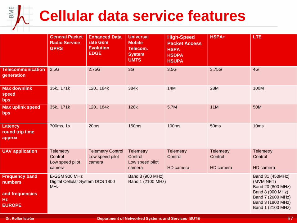
Cellular data service features
General Packet
Radio Service
GPRS
Enhanced Data
rate Gsm
Evolution
EDGE
Universal
Mobile
Telecom.
System
UMTS
High-Speed
Packet Access
HSPA
HSDPA
HSUPA
HSPA+ LTE
Telecommunication
generation
2.5G 2.75G 3G 3.5G 3.75G 4G
Max downlink
speed
bps
35k.. 171k 120.. 184k 384k 14M 28M 100M
Max uplink speed
bps
35k.. 171k 120.. 184k 128k 5.7M 11M 50M
Latency
round trip time
approx.
700ms, 1s 20ms 150ms 100ms 50ms 10ms
UAV application Telemetry
Control
Low speed pilot
camera
Telemetry Control
Low speed pilot
camera
Telemetry
Control
Low speed pilot
camera
Telemetry
Control
HD camera
Telemetry
Control
HD camera
Telemetry
Control
HD camera
Frequency band
numbers
and frequencies
Hz
EUROPE
E-GSM 900 MHz
Digital Cellular System DCS 1800
MHz
Band 8 (900 MHz)
Band 1 (2100 MHz)
Band 31 (450MHz)
(MVM NET)
Band 20 (800 MHz)
Band 8 (900 MHz)
Band 7 (2600 MHz)
Band 3 (1800 MHz)
Band 1 (2100 MHz)
67Department of Networked Systems and Services BUTEDr. Koller István
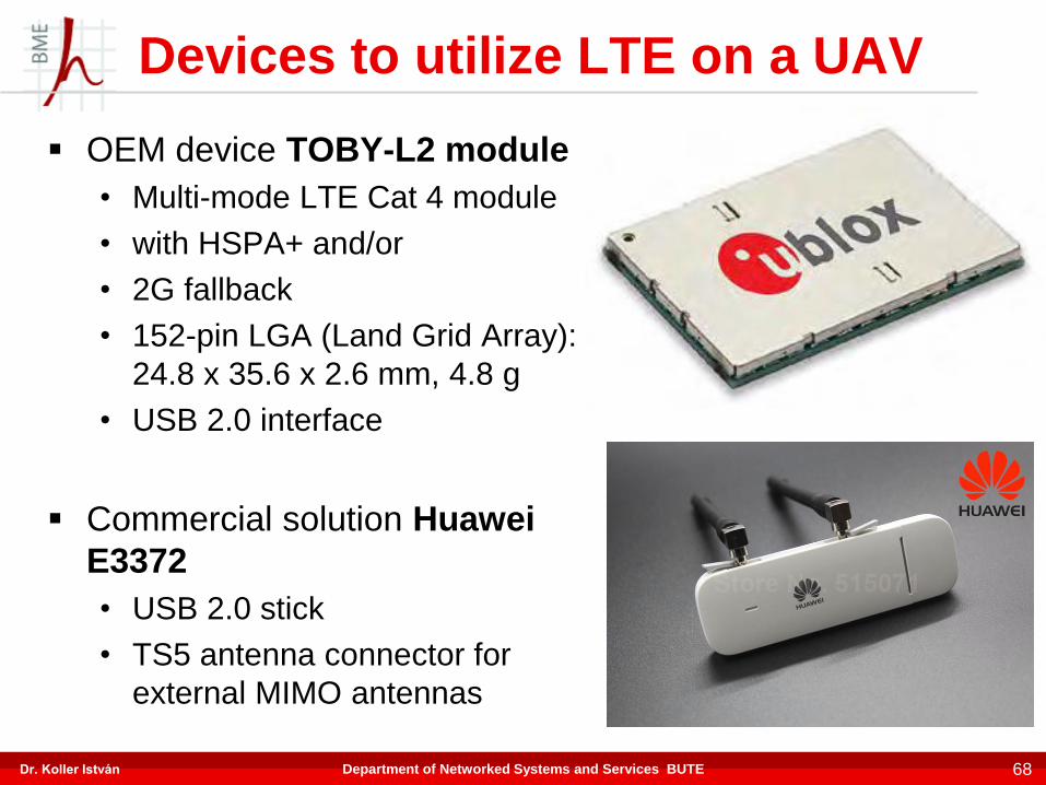
Devices to utilize LTE on a UAV
OEM device TOBY-L2 module
• Multi-mode LTE Cat 4 module
• with HSPA+ and/or
• 2G fallback
• 152-pin LGA (Land Grid Array):
24.8 x 35.6 x 2.6 mm, 4.8 g
• USB 2.0 interface
Commercial solution Huawei
E3372
• USB 2.0 stick
• TS5 antenna connector for
external MIMO antennas
68Department of Networked Systems and Services BUTEDr. Koller István

ISM bands for Telemetry, Control,
Payload
69BME HIT
ISM bands – no need of licencse
• 169,4.. 169,475 MHz – Automatic Metering – low speed
(telemetry/control)
• 433,05.. 434,79 MHz - telemetry
• 868,7.. 869 MHz - telemetry
• 2400.. 2483.5 MHz – (WiFi, microwave ovens..) telemetry,
payload video (analog, digital)
• 5800 MHz - telemetry, payload
Dr. Koller István

Telecommunication satellite systems
Satellite system IRIDIUM GLOBALSTAR INMARSAT THURAYA
Orbit LEO LEO GEO GEO
Altitude 780 km 1412 km ~36 000 km ~36 000 km
Number of
satellites
66 sats / 6 orbits 48 sats / 8 orbits 4 sats 2 sats
Frequency
bands
L (1.6GHz),
Ka (26..40GHz)
L,
Ku (12.. 18GHz)
L, Ku L, Ku
Services voice (2,4 kbps), voice (9,6 kbps), voice/VoIP (4
kbps)
voice (9,6 kbps),
data / ISP
(2,4 kbps)
Data (9,6 kbps) ISDN (64kbps),
IP (492 kbps)
data (9,6 kbps),
fax (9,6 kbps),
IP (144 kbps),
70Dr. Koller István Department of Networked Systems and Services BUTE
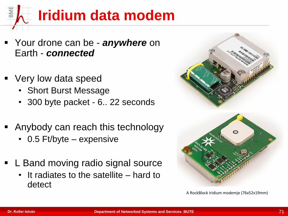
Iridium data modem
Your drone can be - anywhere on Earth - connected
Very low data speed
• Short Burst Message
• 300 byte packet - 6.. 22 seconds
Anybody can reach this technology
• 0.5 Ft/byte – expensive
L Band moving radio signal source
• It radiates to the satellite – hard to detect
71
A RockBlock Iridium modemje (76x52x19mm)
Dr. Koller István Department of Networked Systems and Services BUTE

ISM band telemetry / control
modems for UAVs
10/9/2017 72BME HIT

Custom Radio link - BBCOM
Ground > UAV control:
• Spread spectrum CHIRP modulation
• 17kbit/s
UAV > Ground Telemetry:
• Spread spectrum CHIRP modulation
• 108 kbit/s
UAV > Ground Payload:
• OFDM modulation
• 108kbaud/s - 1 symbol - 100bit: 10.8 Mbit/s
5GHzband – 20MHz bandwith
73BME HITDr. Koller István

Timing of BBCOM operation
74BME HIT
CHIRP
OFDM
3.7ms
10 msec
1.0 ms 1.0 ms
UP Link
DOWN Link
3.7ms
CHIRP
OFDM
0.6ms
time
CHIRP
CHIRP
CHIRP
10 msec
UP Link
DOWN Link
Dr. Koller István
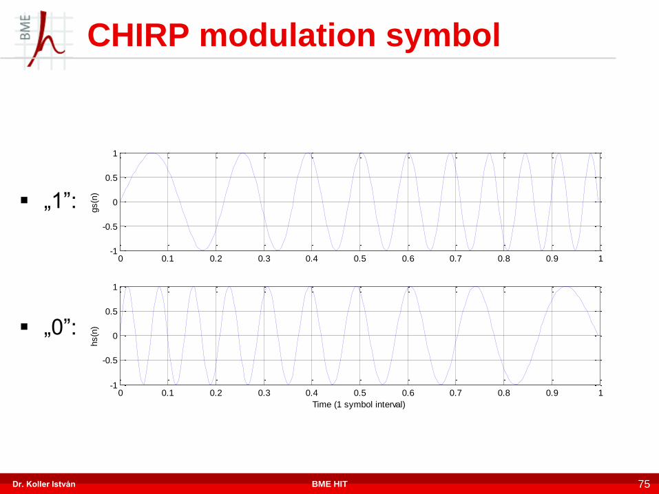
CHIRP modulation symbol
75BME HIT
0 0.1 0.2 0.3 0.4 0.5 0.6 0.7 0.8 0.9 1-1
-0.5
0
0.5
1
gs(n
)
0 0.1 0.2 0.3 0.4 0.5 0.6 0.7 0.8 0.9 1-1
-0.5
0
0.5
1
Time (1 symbol interval)
hs(n
)
„1”:
„0”:
Dr. Koller István

CHIRP Generation of the CHIRP signal
76BME HIT
analog output
Memory
with UpChirp
D/A Up/down counter
clock
bit
Dr. Koller István

0 100 200 300 400 500 600 700 800 900 1000-1
-0.8
-0.6
-0.4
-0.2
0
0.2
0.4
0.6
0.8
1
Sample
Diffe
rential outp
ut
CHIRP demodulator
10/9/2017 77BME HIT
A/D
Matched filter „1”
clock
databit
Differentialsignal
"1"Symbol
Matched filter „0”
„0"Symbol
input
Differentialsingnal -databit

OFDM transmitter
78BME HIT
Errorcorrectionencoder
Frequencydomainvectors
1 : 2
Input bits
Analogoutput
Time domain
Inverz Fourier trans-
formationD/A
FrequencydomainRedundant
bits
Dr. Koller István
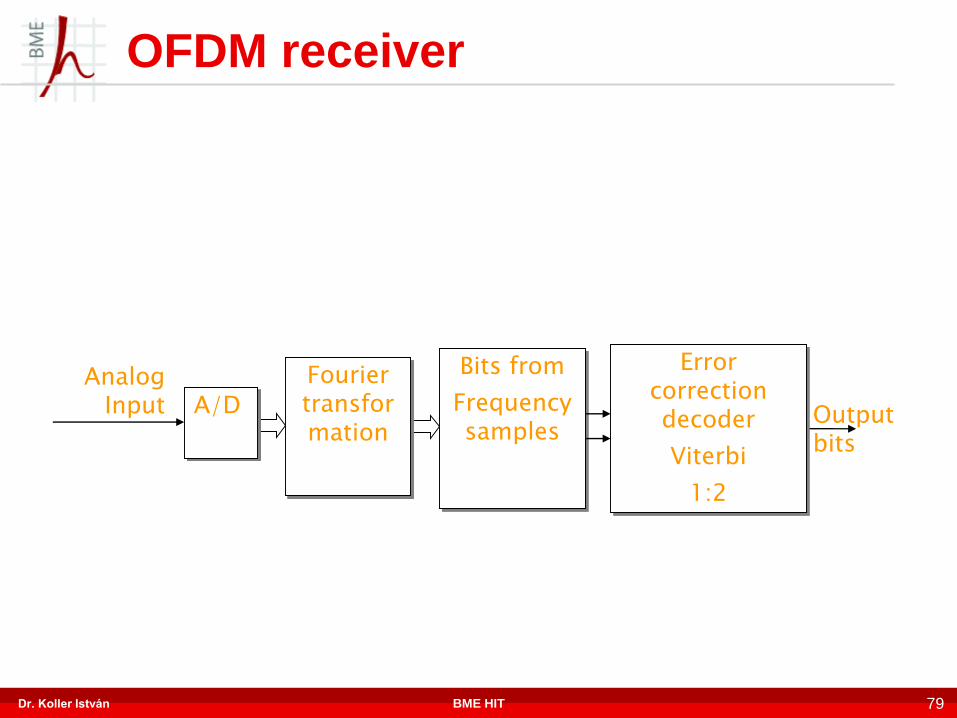
OFDM receiver
79BME HIT
A/D
Fourier transformation
Bits from
Frequencysamples
Output bits
AnalogInput
Errorcorrectiondecoder
Viterbi
1:2
Dr. Koller István

OFDM parameters
80BME HIT
Sampling frequency: fs = 94 MHz
FFT point munber: NFFT = 256
Guard Time : NGUA = 64 (25 %)
Sample / symbol: NTOT = 320
Carrier number: M = 50 + 1 pilot
Frequency gaps: 1875.367256
94
FFT
s
N
ff kHz
Carriers: fk = k * fs / NFFT k = 39, 40, …..,88,89
Modulation: Differential QPSK (DQPSK )
1.
39.
14.32
MHz
40.
14.69
MHz
41.
42.
63
23.13
MHz
64.
23.50
MHz
65.
23.87
MHz
87.
88.
32.31
MHz
89.
32.68
MHz
. . . . . . . .
Pilot
fk
k
2. 3. 4. 25. 26. 50. 49. 48.
Dr. Koller István
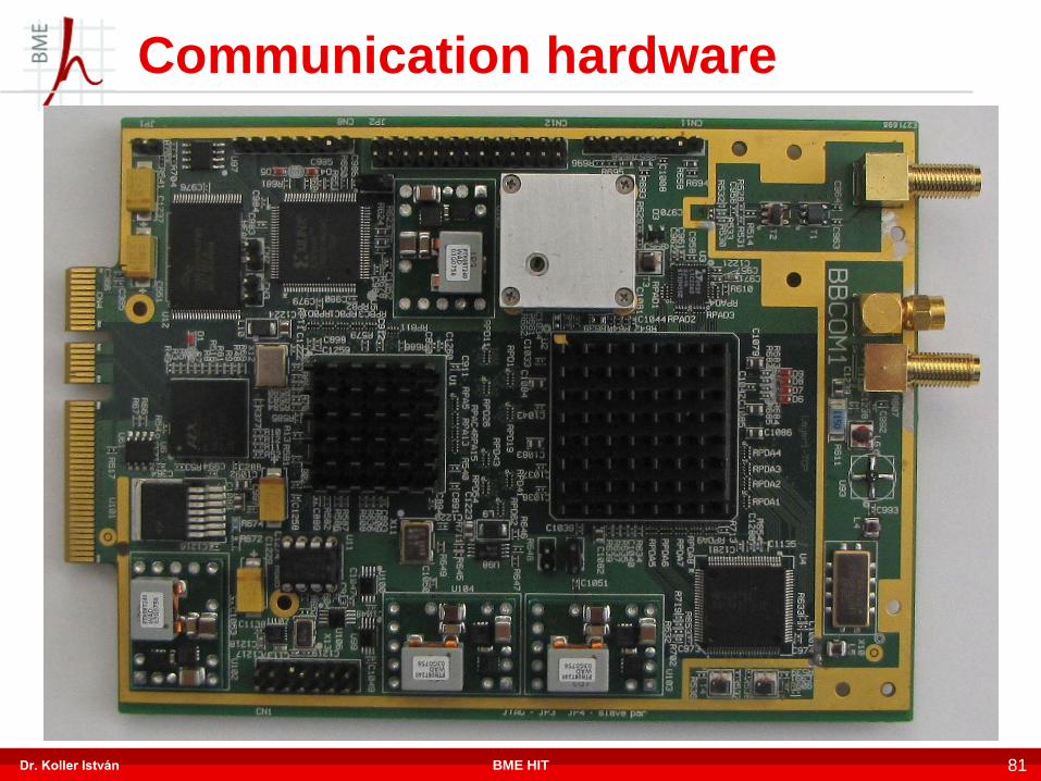
Communication hardware
81BME HITDr. Koller István

Communication mode numberUp
Chirp
Down
ChirpOFDM
1Near (0..12 km* )
Single Chirp,
OFDM - 1:2 Viterbi
12
kb/s
100
kb/s
5
Mb/s
2Far (12.. ~17 km)
Single Chirp,
OFDM - 1:4 Viterbi
12
kb/s
100
kb/s
2.5
Mb/s
3Farther
(~17.. ~30 km)
Chirp without OFDM
12
kb/s
200
kb/s-
4Very far
(~30.. ~40km)
Double chirp
5
kb/s
100
kb/s-
*:OFDM data, 5GHz, 250mW, 2dBi, 16dBi, measured by BHE on UAV82
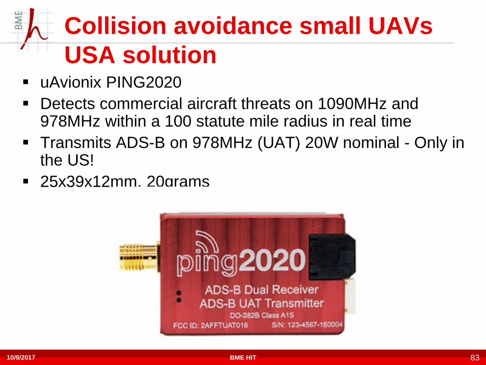
Collision avoidance small UAVs
USA solution uAvionix PING2020
Detects commercial aircraft threats on 1090MHz and 978MHz within a 100 statute mile radius in real time
Transmits ADS-B on 978MHz (UAT) 20W nominal - Only in the US!
25x39x12mm, 20grams
10/9/2017 83BME HIT

ADS-B in Europe - now only in UK
10/9/2017 84BME HIT
uAvionix PING1090
Detects commercial aircraft threats on 1090MHz and 978MHz within a 100 statute mile radius in real time
Transmits ADS-B on 1090MHz, 20W nominal - Certification for UK
25x39x12mm, 20grams
ADS-B everywhere – just receiver
10/9/2017 85BME HIT
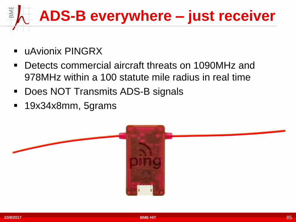
uAvionix PINGRX
Detects commercial aircraft threats on 1090MHz and
978MHz within a 100 statute mile radius in real time
Does NOT Transmits ADS-B signals
19x34x8mm, 5grams
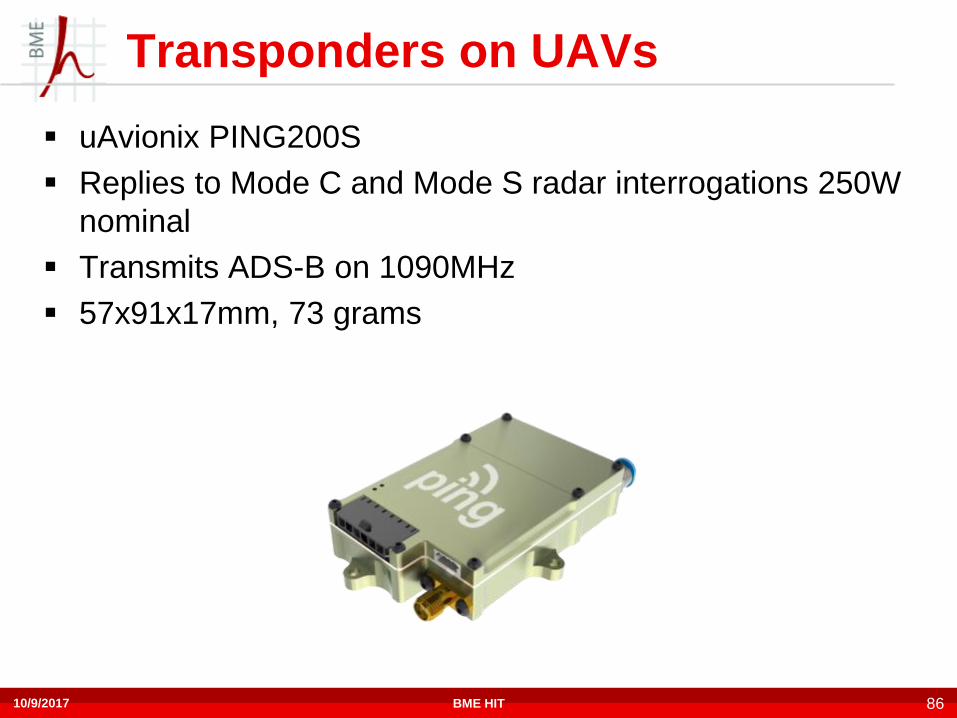
Transponders on UAVs
10/9/2017 86BME HIT
uAvionix PING200S
Replies to Mode C and Mode S radar interrogations 250W
nominal
Transmits ADS-B on 1090MHz
57x91x17mm, 73 grams

Radio link parameters
Mostly Point to Point link – typical, and simplest
• Rarely Point to Multi point
• Typically Line of Site connection
Three communication channels
• Must be robust, reliable:
• Command channel – Ground to UAV
• Telemetry channel – UAV to ground
• Generally must be high-speed:
• Payload - UAV to ground
Dr. Istvan Koller 87Department of Networked Systems and Services BUTE
General radio technology knowledges
About the radio channel
Range of radio channel
88BME HITDr. Koller István

Attennuation between teransmitter and receiver
Simplest model – one way propagation
Dr. Istvan Koller
AMOR
ES
89
Department of Networked Systems and Services BUTE
Transmitter antenna Receiver antenna
:Transmitter antenna Gain
d: distance
:Transmitted Power
S: Transmitted Power density : Received Power
: Effective Receiver antenna Area – antenna Aperture
: Wavelength
:: Receiver antenna Gain

Attennuation between transmitter
reciver – free space model
In dB:
Dr. Istvan Koller 90Department of Networked Systems and Services BUTE
a0[dB]=10⋅lg(4πRλ)2
RTR
T
GGλ
π d
P
Patt
142
R
TdB
P
Patt lg10
RT
dB GGλ
π datt
4log20

Free space attenuation –
satellite - satellite
Dr. Istvan Koller 91Department of Networked Systems and Services BUTE
λ
π dattdB
FreeSpace
4log20
Attenuation (dB) Distance
Wavelength Frequency 10m 100m 1km 10km 100km
300 m 1 MHz - - - 52 72
30 m 10 MHz - - 52 72 92
3 m 100 MHz - 52 72 92 112
0.3 m 1 GHz 52 72 92 112 132
3 cm 10 GHz 72 92 112 132 152
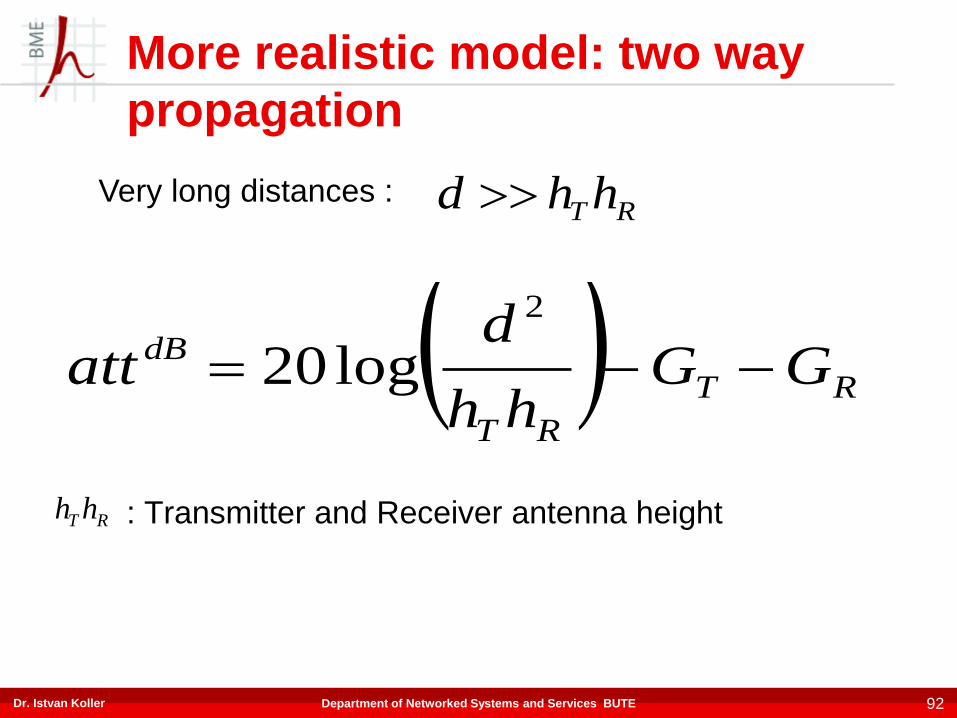
More realistic model: two way
propagation
: Transmitter and Receiver antenna height
Dr. Istvan Koller 92Department of Networked Systems and Services BUTE
RT
RT
dB GGhh
datt
2
log20
RT hh
Very long distances :RT hhd
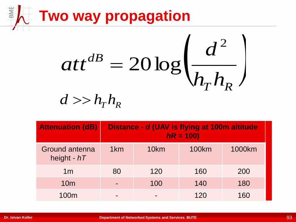
Two way propagation
Dr. Istvan Koller 93Department of Networked Systems and Services BUTE
RT
dB
hh
datt
2
log20
Attenuation (dB) Distance - d (UAV is flying at 100m altitude
hR = 100)
Ground antenna
height - hT
1km 10km 100km 1000km
1m 80 120 160 200
10m - 100 140 180
100m - - 120 160
RT hhd

Link Budget
Signal level at receiver input:
Dr. Istvan Koller 94Department of Networked Systems and Services BUTE
attPP TXRX Minimum input power is defined by sensitivity
F.e. a 5GHz WISP station (WiFi) data:
• PTX=23dBm: 23=10log(p/1mW) > PTX = 200mW
• Sensitivity: (MCS1-QPSK 10Mbit/s) – 96dBm
• Zero gain antennas: 119 dB attenuation is possible: ~ 10km
range
Big problem: fading – variation of the transmission relatively
fast because of the moving device
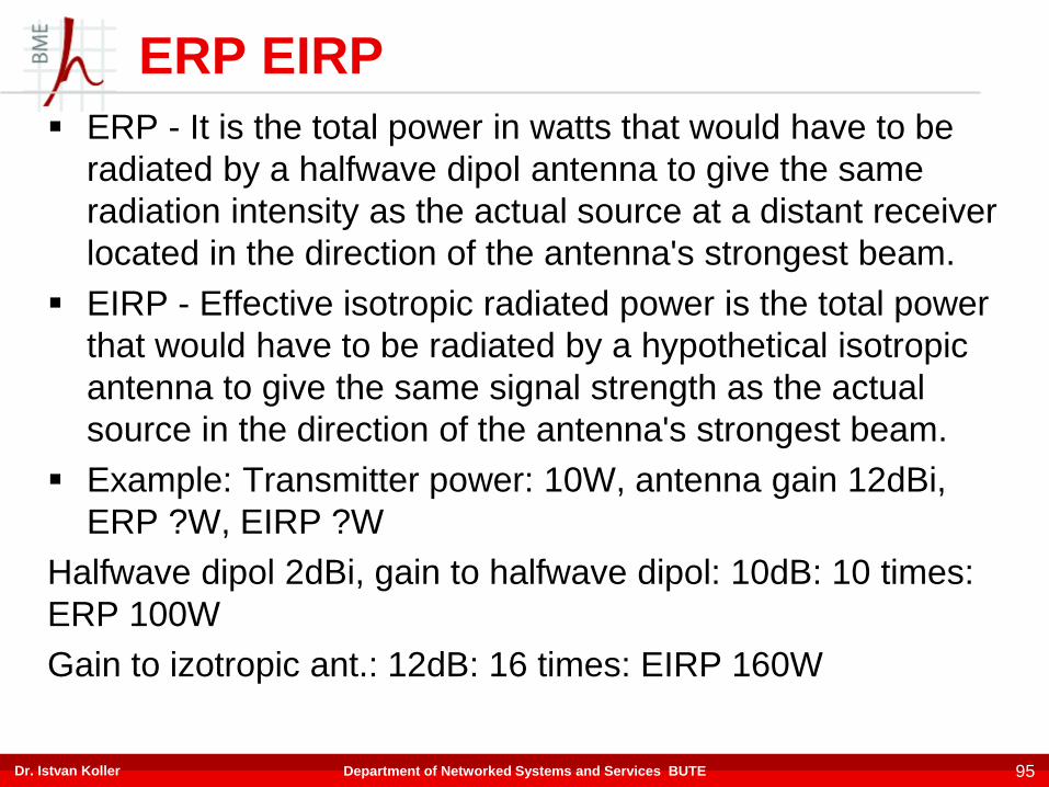
ERP EIRP
ERP - It is the total power in watts that would have to be
radiated by a halfwave dipol antenna to give the same
radiation intensity as the actual source at a distant receiver
located in the direction of the antenna's strongest beam.
EIRP - Effective isotropic radiated power is the total power
that would have to be radiated by a hypothetical isotropic
antenna to give the same signal strength as the actual
source in the direction of the antenna's strongest beam.
Example: Transmitter power: 10W, antenna gain 12dBi,
ERP ?W, EIRP ?W
Halfwave dipol 2dBi, gain to halfwave dipol: 10dB: 10 times:
ERP 100W
Gain to izotropic ant.: 12dB: 16 times: EIRP 160W
Dr. Istvan Koller 95Department of Networked Systems and Services BUTE