radio remote control m880 user’s manual...0 $// (1 grf[ 4. significance of the symbols in labels...
TRANSCRIPT
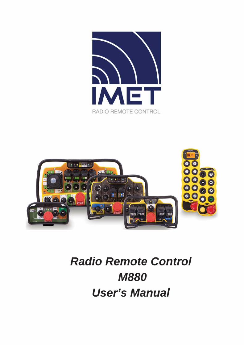
Radio Remote Control M880
User’s Manual
CONTENTS CONTENTS ............................................................................................................................................................ 2
INTRODUCTION................................................................................................................................................... 4
1. IDENTIFICATION DATA ......................................................................................................................... 5
1.1. DOCUMENTATION .......................................................................................................................................... 7
2. CONVENTIONS USED IN THIS MANUAL ............................................................................................ 7
3. CAUTION .................................................................................................................................................... 7
3.1. RISK ANALYSIS ................................................................................................................................................ 73.2. APPLICATIONS ................................................................................................................................................ 7
4. SIGNIFICANCE OF THE SYMBOLS IN LABELS ................................................................................. 8
5. FCC-REGULATORY INFORMATION (2,4 GHZ RADIO MODULE) ................................................... 8
6. PREVENTIVE MAINTENANCE .............................................................................................................. 9
6.1. ROUTINE MAINTENANCE TO BE CARRIED OUT BY THE OPERATOR....................................................................... 96.2. MAINTENANCE AND INTERNAL CHECKS ............................................................................................................ 9
7. INSTALLING THE RADIO REMOTE CONTROL ................................................................................ 10
7.1. RECEIVING UNIT DIMENSIONS AND DRILLING DIAGRAM .................................................................................. 117.2. CONNECTING THE RECEIVER ......................................................................................................................... 127.3. INSTALLING THE EXTERNAL ANTENNA ............................................................................................................ 137.4. STOP (E-STOP) .......................................................................................................................................... 147.5. SAFETY ENABLE (S-ENABLE) ................................................................................................................. 147.6. BASIC FUNCTIONS BOARD PCB201 (DC) / PCB231 (AC) (SERVICE CARD) .................................................... 167.7. CONNECTION DIAGRAMS OF H RECEIVERS ..................................................................................................... 167.8. HDC (PCB200) RECEIVER WITH ANALOG OUTPUT CARDS AND DATA FEEDBACK CARD ................................... 177.9. HAC (PCB230) RECEIVER WITH ANALOG OUTPUT CARDS AND DATA FEEDBACK CARDS .................................. 187.10. POWER SUPPLY CONNECTIONS OF HDC AND HAC RECEIVERS ....................................................................... 197.11. ANALOG COMMAND BOARD (PCB261) .......................................................................................................... 207.12. LOGIC BOARD (PCB260) .............................................................................................................................. 217.13. DATA FEEDBACK CARD (PCB262) ................................................................................................................ 227.14. RELAY CARDS ............................................................................................................................................... 237.15. BOARDS WITH SOLID STATE RELAYS (MOSFET) ............................................................................................. 257.16. POTENTIOMETER CARD (M880DT2) ............................................................................................................. 267.17. CONNECTION DIAGRAMS FOR L RECEIVERS .................................................................................................... 277.18. M880 LDC VERSION (PCB100) ................................................................................................................... 277.19. M880 LAC VERSION (PCB130) ................................................................................................................... 287.20. RELAY BOARD FOR M880 LAC AND M880 LDC RECEIVERS ........................................................................... 297.21. OTHER COMMAND BOARDS FOR M880 LDC .................................................................................................. 307.22. CONNECTION DIAGRAMS FOR M RECEIVERS .................................................................................................. 317.23. M880 MAC VERSION (PCB300) .................................................................................................................. 317.24. SERIAL DATA TRANSMISSION .......................................................................................................................... 327.25. USER SERIAL (RS232/RS485) ....................................................................................................................... 327.26. SERIAL CONNECTION CABLE .......................................................................................................................... 32
8. USING THE RADIO REMOTE CONTROL ........................................................................................... 33
8.1. SAFETY RULES .............................................................................................................................................. 338.2. POWERING AND STARTING THE RADIO REMOTE CONTROL ............................................................................... 338.3. THE STOP FUNCTION .................................................................................................................................. 338.4. TURNING OFF THE REMOTE CONTROL............................................................................................................ 348.5. AUTO POWER-OFF (TIME-OUT) ..................................................................................................................... 348.6. TRANSMITTER INDICATOR LEDS.................................................................................................................... 348.7. TRANSMITTING UNIT POWER SUPPLY .............................................................................................................. 368.8. BATTERY STATUS OF CHARGE ........................................................................................................................ 368.9. CHANGING AND CHARGING THE BATTERY ...................................................................................................... 36
9. CHANGING THE OPERATING FREQUENCY .................................................................................... 37
9.1. INITIAL CONDITIONS FOR THE FREQUENCY CHANGE ....................................................................................... 379.2. FREQUENCY CHANGE PROCEDURE ................................................................................................................ 37
9.3. AVAILABLE FREQUENCIES (433-434 MHZ RADIO MODULE) ........................................................................... 389.4. AVAILABLE FREQUENCIES (2,4 GHZ RADIO MODULE) .................................................................................... 39
10. DSC (DYNAMIC SPEED CONTROL) OPTION .................................................................................... 39
11. TROUBLESHOOTING ............................................................................................................................ 40
11.1. MALFUNCTIONS IN THE TRANSMITTER’S STOP CIRCUIT ................................................................................. 4111.2. PASSIVE EMERGENCY ................................................................................................................................... 4111.3. TECHNICAL ASSISTANCE ............................................................................................................................... 41
12. TECHNICAL SPECIFICATIONS ........................................................................................................... 42
12.1. CE RADIO MODULE (433-434 MHZ) ............................................................................................................ 4212.2. CE, FCC, IC, ARIB RADIO MODULE (2,4 GHZ) ............................................................................................ 4212.3. TRANSMITTER ............................................................................................................................................... 4312.4. M880 HDC / M880 HAC RECEIVERS ........................................................................................................... 4512.5. M880 LDC / M880 LAC RECEIVERS ............................................................................................................ 4712.6. M880 MAC RECEIVERS ................................................................................................................................ 4912.7. CB3600-AC, CB3600-DC BATTERY CHARGER FOR THOR2, ZEUS2, ARES2 AND KRON TRANSMITTERS ..... 5012.8. CB36NIMH BATTERY CHARGER FOR THOR2, ZEUS2, ARES2 AND KRON TRANSMITTERS .......................... 5112.9. CB36NIMH G4 - BATTERY CHARGER M880 G4L AND M880 G4S TRANSMITTERS .......................................... 5212.10. CB37LION BATTERY CHARGER FOR WAVE2 TRANSMITTERS ......................................................................... 53
13. RADIO REMOTE CONTROL SPARE PARTS LIST ............................................................................. 54
13.1. TRANSMITTING UNITS AND BATTERY CHARGER ............................................................................................... 5413.2. HDC RECEIVER ........................................................................................................................................... 5413.3. HAC RECEIVER ............................................................................................................................................ 5413.4. LDC RECEIVER ............................................................................................................................................ 5413.5. LAC RECEIVER ............................................................................................................................................ 5413.6. MAC RECEIVER ........................................................................................................................................... 55
14. DISPOSAL (EU ZONE) ............................................................................................................................ 55
15. ANNEXES ................................................................................................................................................. 55
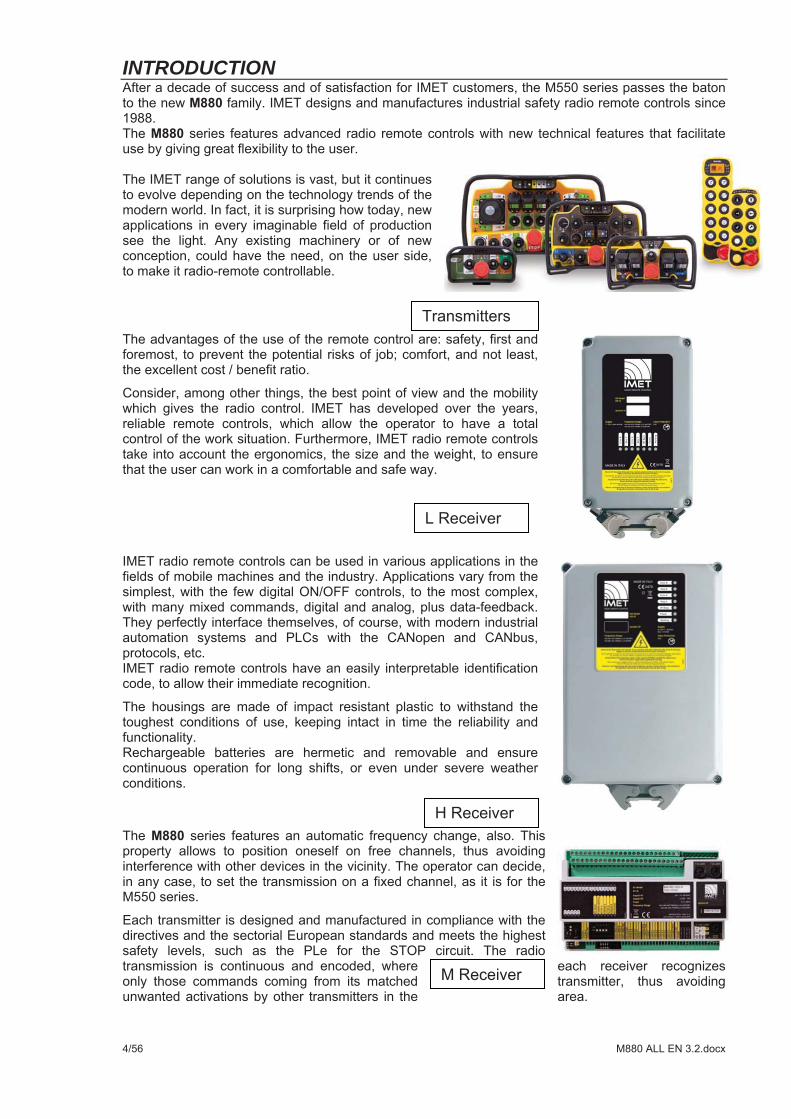
INTRODUCTION
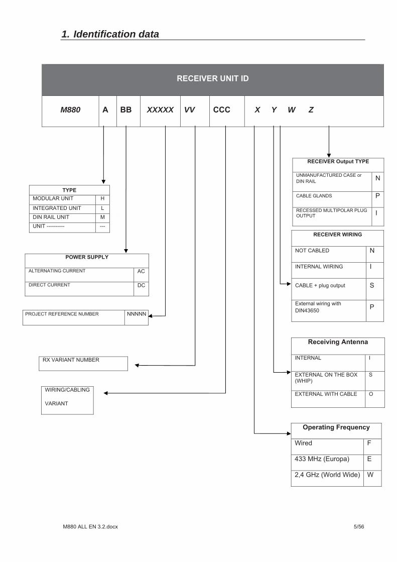
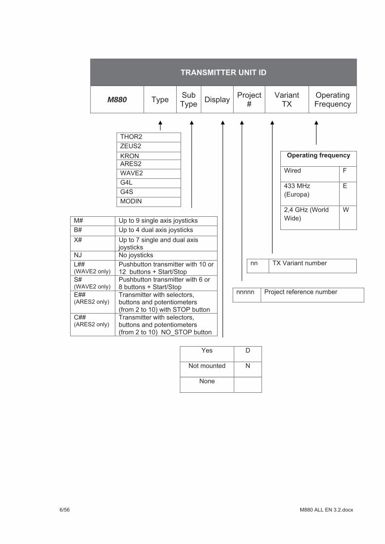
1. Identification data
M880
XXXXX VV X Y W Z
M880
1.1. Documentation
2. CONVENTIONS USED IN THIS MANUAL
Warning:
Danger:
Note:
3. CAUTION
3.1. Risk analysis
3.2. Applications
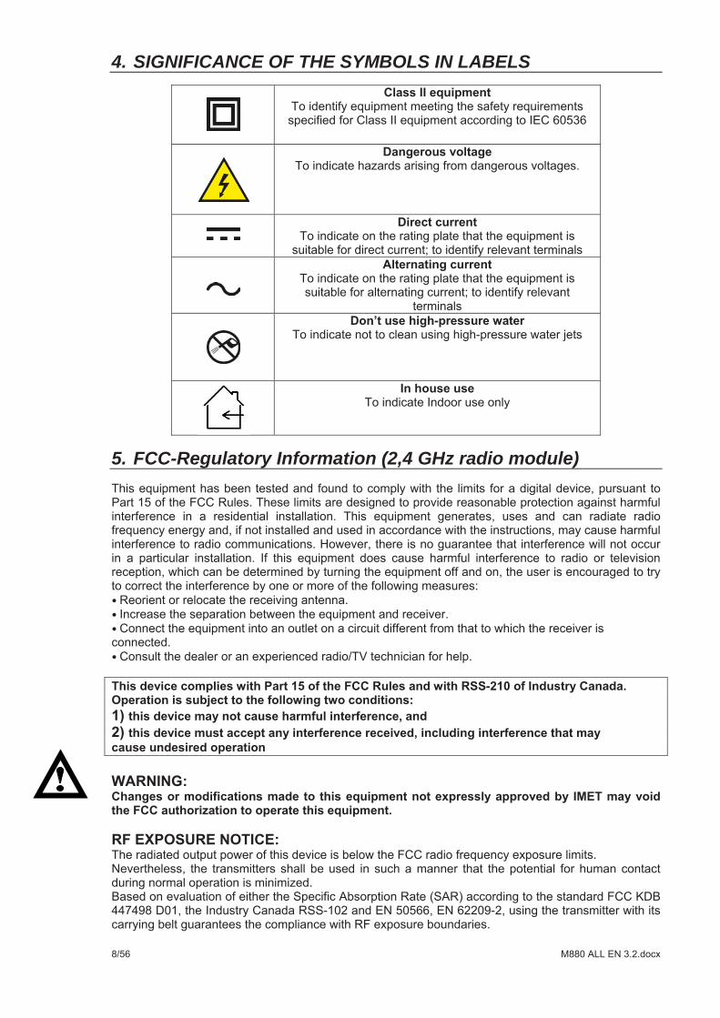
4. SIGNIFICANCE OF THE SYMBOLS IN LABELS
5. FCC-Regulatory Information (2,4 GHz radio module)
6. PREVENTIVE MAINTENANCE
6.1. Routine maintenance to be carried out by the operator
6.2. Maintenance and internal checks
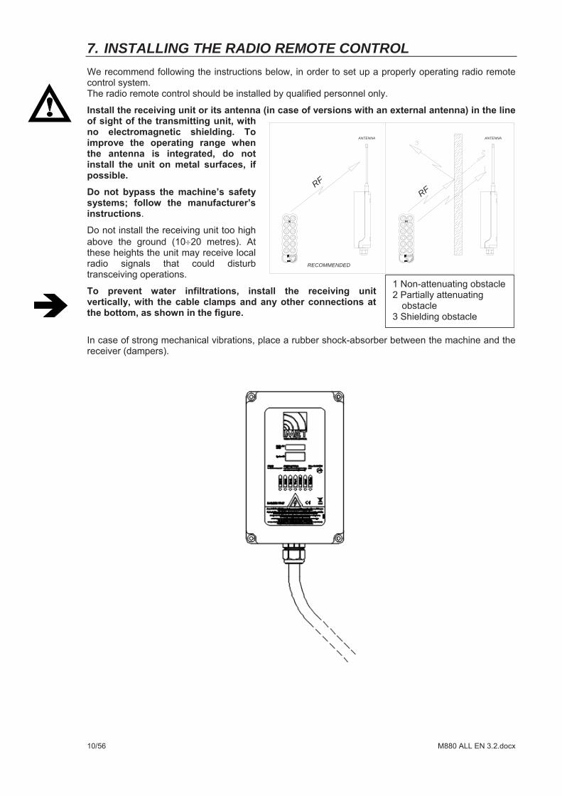
7. INSTALLING THE RADIO REMOTE CONTROL
RF
ANTENNA ANTENNA
RF
RECOMMENDED
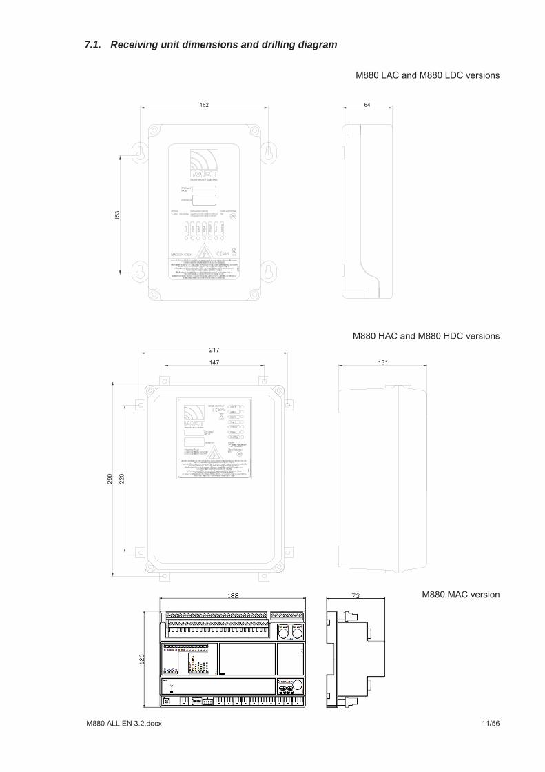
7.1. Receiving unit dimensions and drilling diagram
7.2. Connecting the receiver
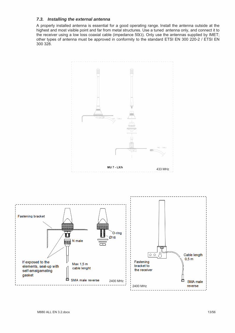
7.3. Installing the external antenna
7.4. STOP (E-STOP)
7.5. SAFETY ENABLE (S-ENABLE)
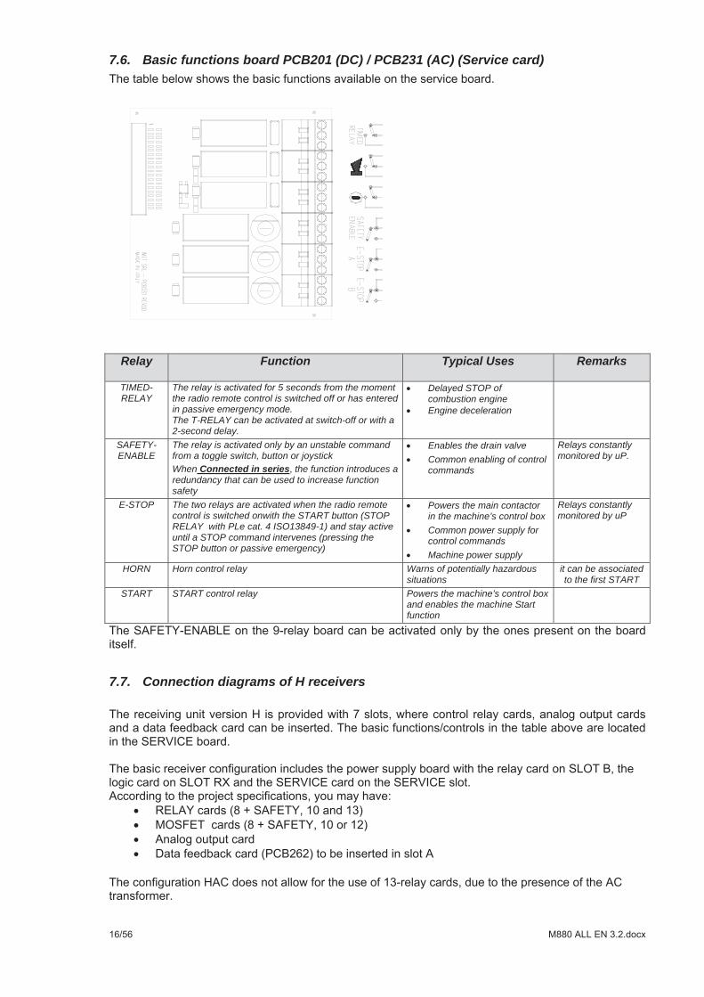
7.6. Basic functions board PCB201 (DC) / PCB231 (AC) (Service card)
7.7. Connection diagrams of H receivers
Relay Function
Typical Uses Remarks
TIMED-RELAY
The relay is activated for 5 seconds from the moment the radio remote control is switched off or has entered in passive emergency mode. The T-RELAY can be activated at switch-off or with a 2-second delay.
Delayed STOP of combustion engine Engine deceleration
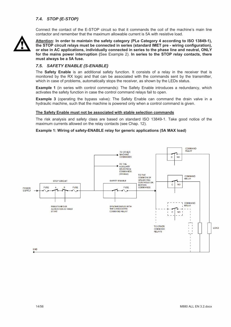
SAFETY-ENABLE
The relay is activated only by an unstable command from a toggle switch, button or joystick When Connected in series the function introduces a redundancy that can be used to increase function safety
Enables the drain valve Common enabling of control commands
Relays constantly monitored by uP.
E-STOP The two relays are activated when the radio remote control is switched onwith the START button (STOP RELAY with PLe cat. 4 ISO13849-1) and stay active until a STOP command intervenes (pressing the STOP button or passive emergency)
Powers the main contactor in the machine’s control box Common power supply for control commands Machine power supply
Relays constantly monitored by uP
HORN Horn control relay Warns of potentially hazardous situations
it can be associated to the first START
START START control relay Powers the machine’s control box and enables the machine Start function
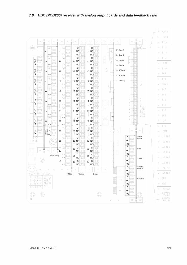
7.8. HDC (PCB200) receiver with analog output cards and data feedback card
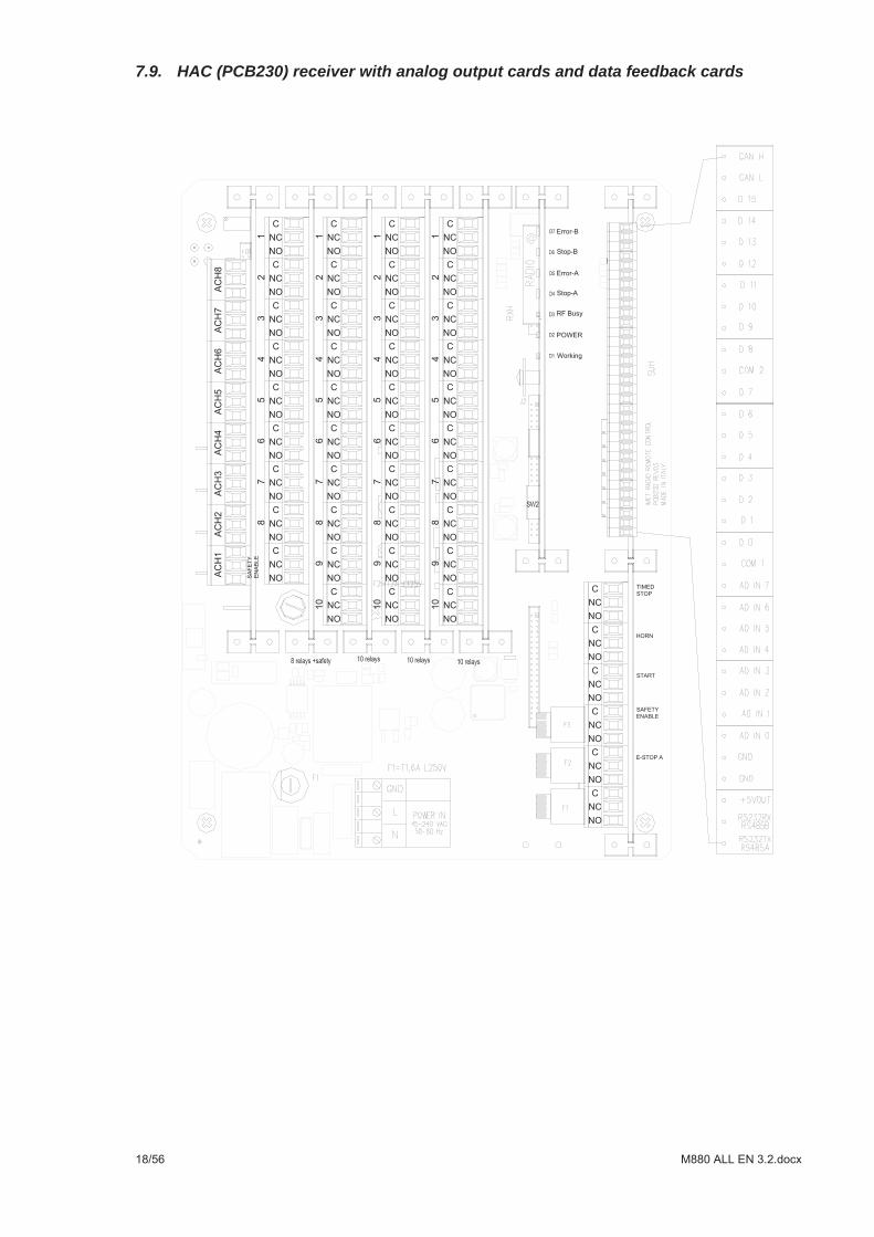
7.9. HAC (PCB230) receiver with analog output cards and data feedback cards
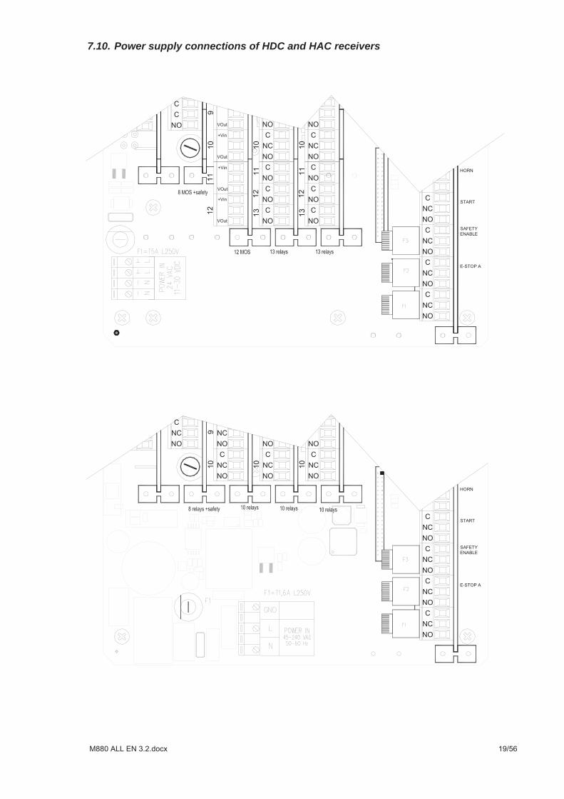
7.10. Power supply connections of HDC and HAC receivers
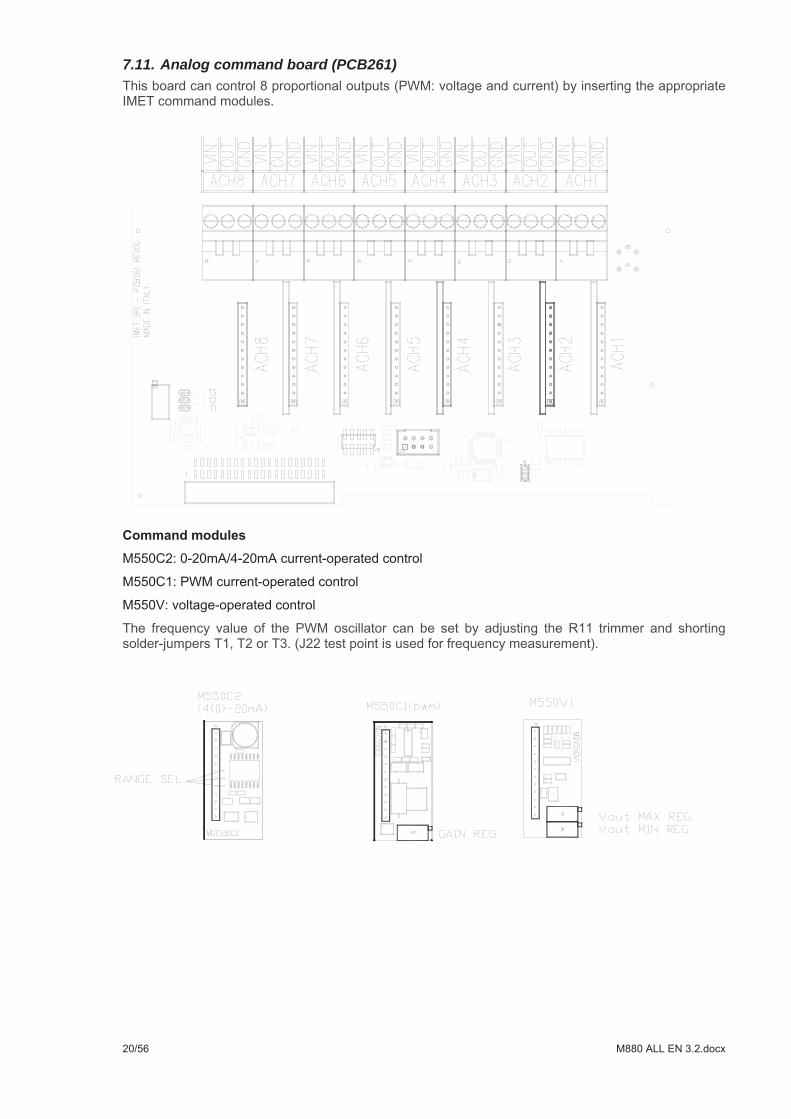
7.11. Analog command board (PCB261)
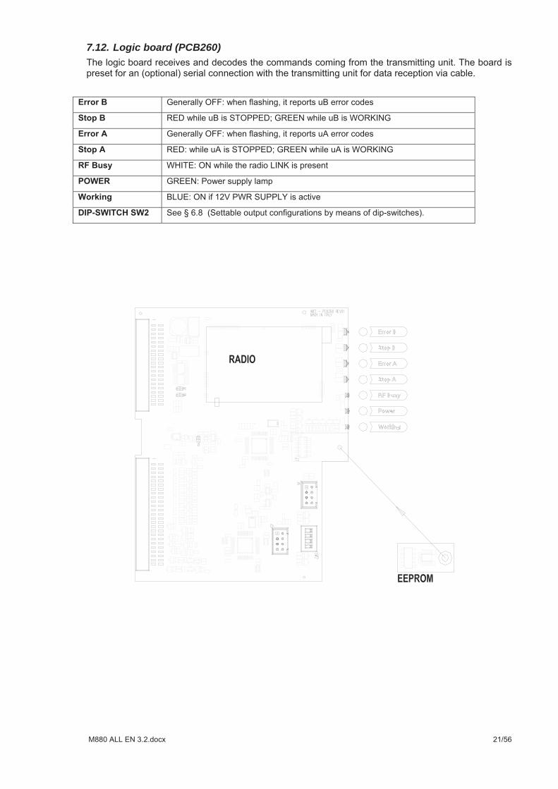
7.12. Logic board (PCB260)
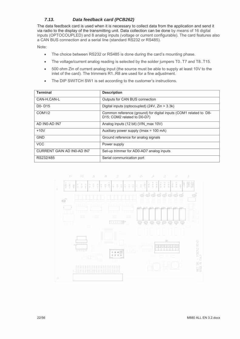
7.13. Data feedback card (PCB262)
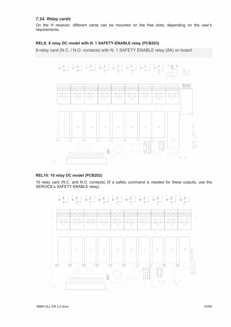
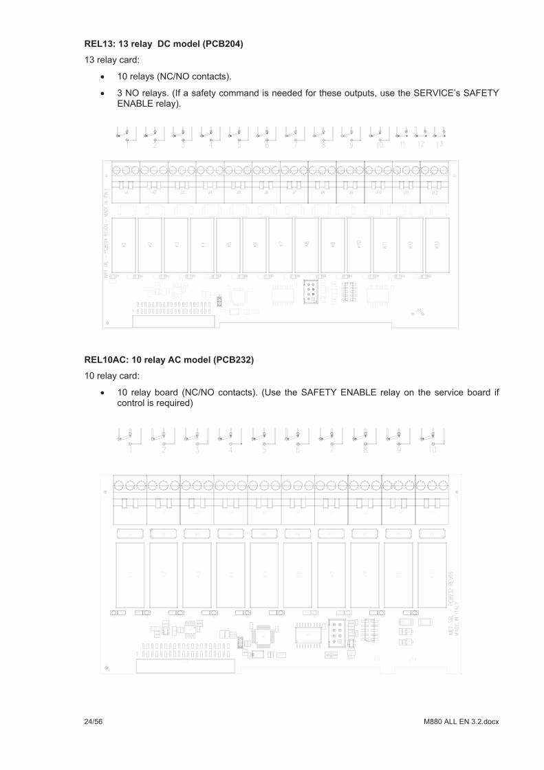
7.14. Relay cards
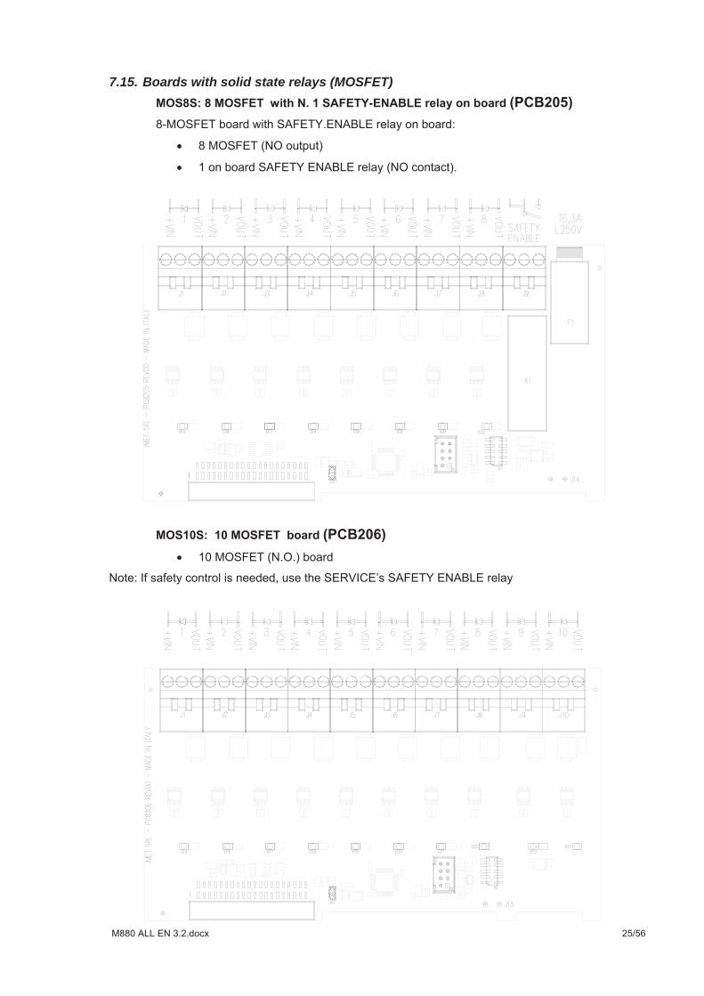
7.15. Boards with solid state relays (MOSFET)
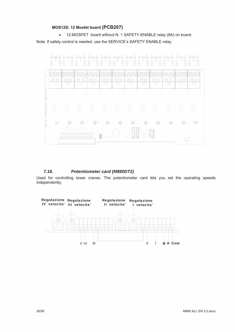
7.16. Potentiometer card (M880DT2)
RegolazioneIII velocita'
RegolazioneIV velocita'
RegolazioneII velocita'
RegolazioneI velocita'
B A Com
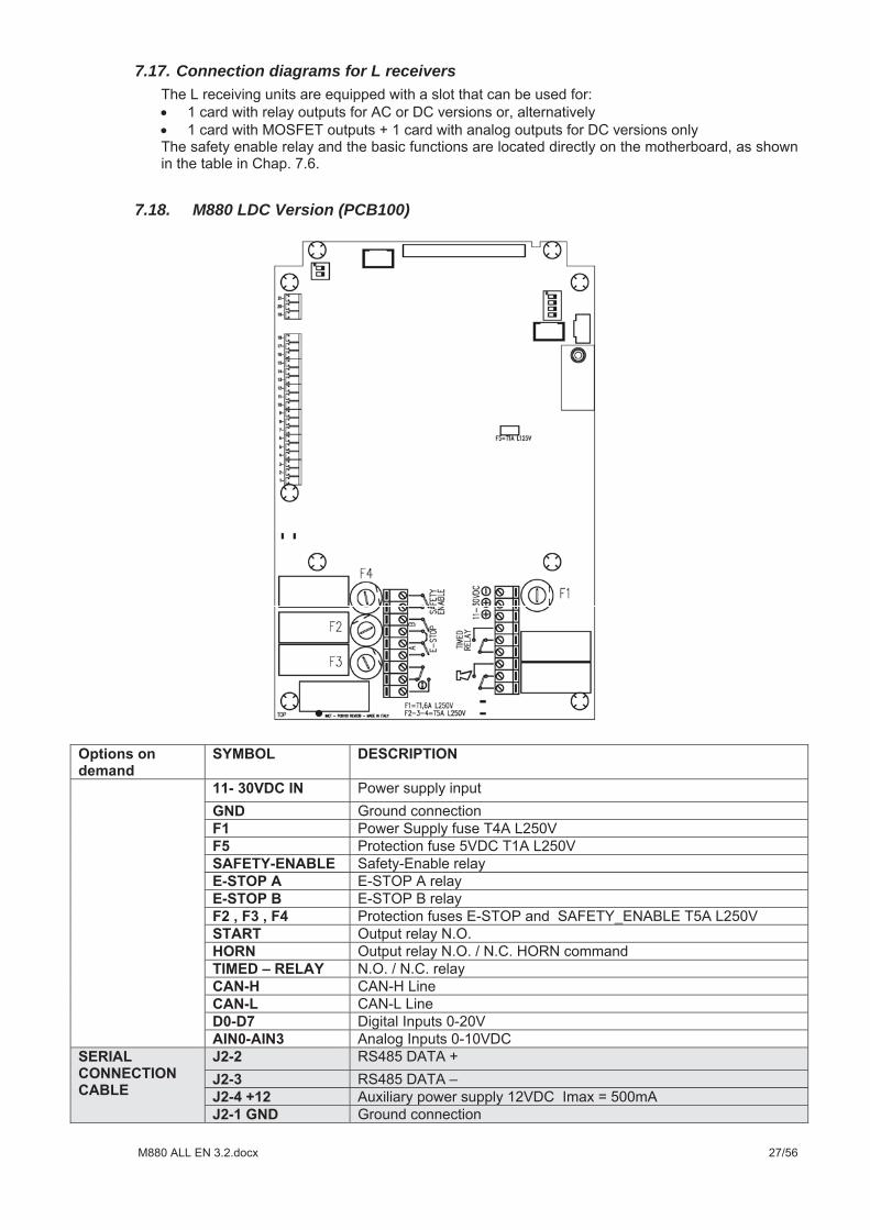
7.17. Connection diagrams for L receivers
7.18. M880 LDC Version (PCB100)
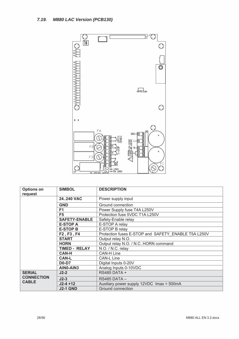
7.19. M880 LAC Version (PCB130)
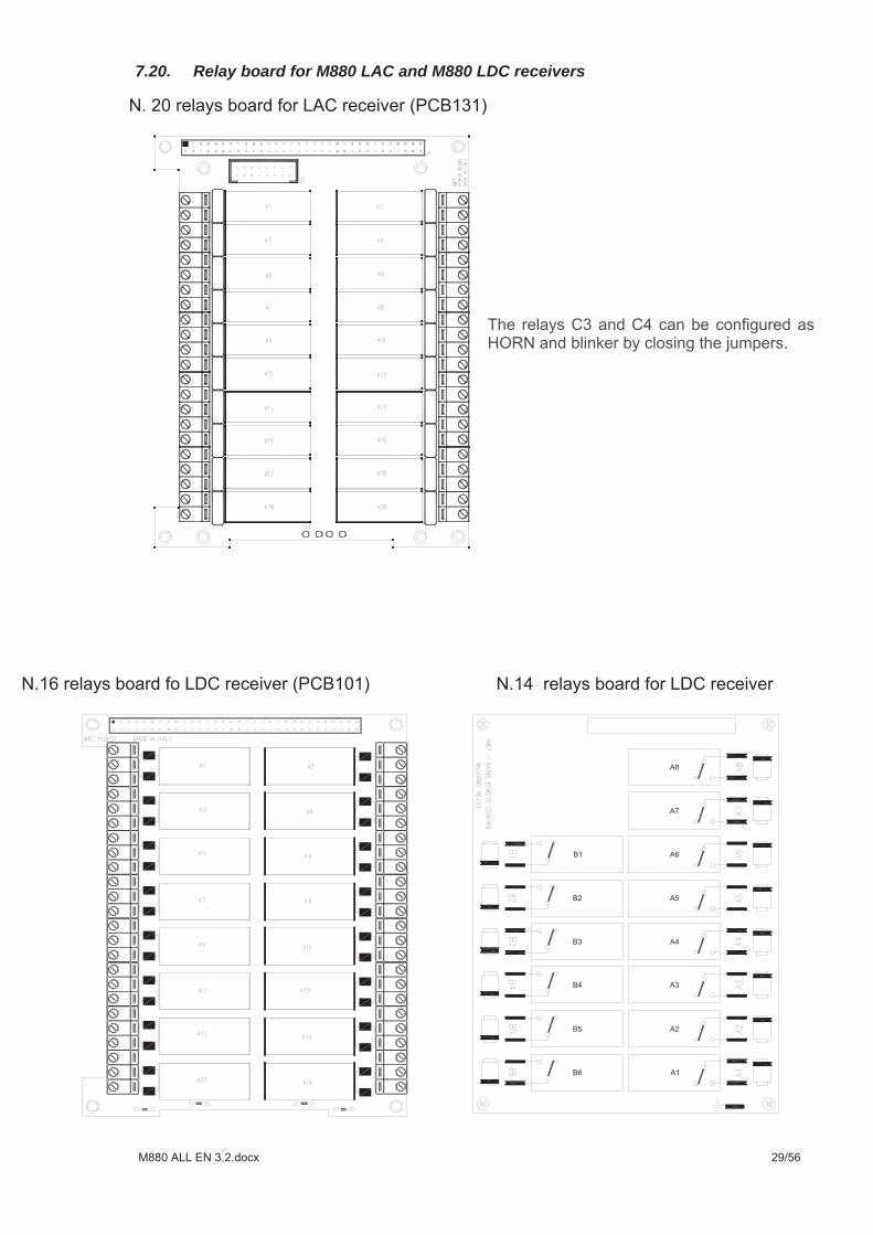
7.20. Relay board for M880 LAC and M880 LDC receivers

7.21. Other command boards for M880 LDC
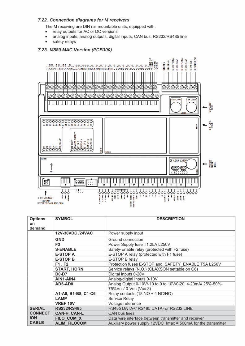
7.22. Connection diagrams for M receivers
7.23. M880 MAC Version (PCB300)
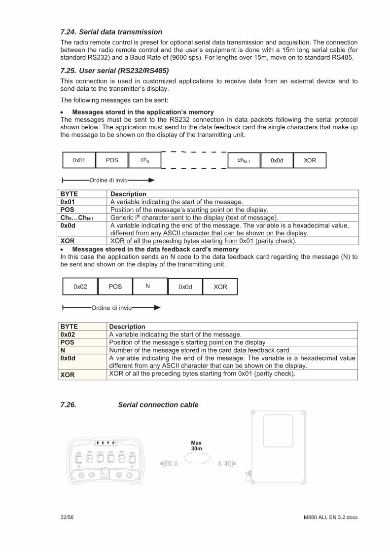
7.24. Serial data transmission
7.25. User serial (RS232/RS485)
7.26. Serial connection cable
8. USING THE RADIO REMOTE CONTROL
8.1. Safety rules
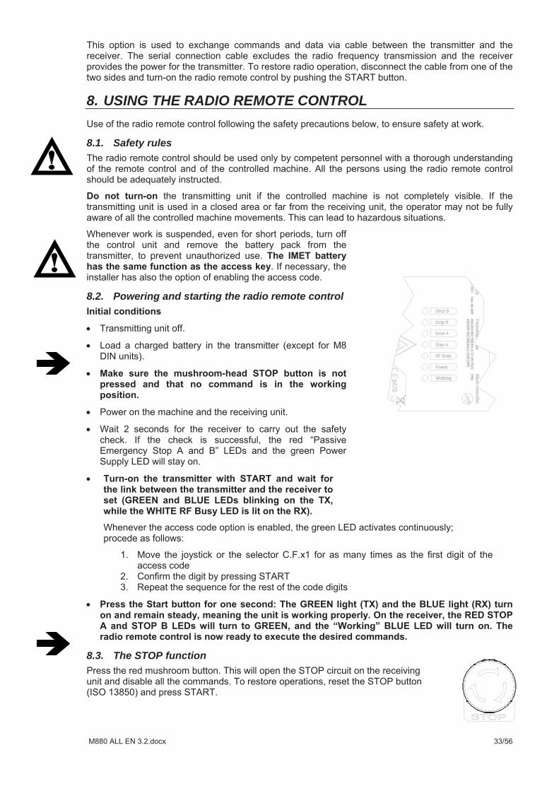
8.2. Powering and starting the radio remote control
8.3. The STOP function
8.4. Turning off the remote control
8.5.
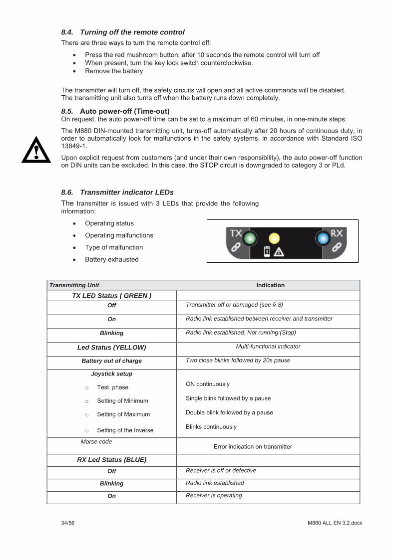
8.6. Transmitter indicator LEDs
Transmitting Unit
TX LED Status ( GREEN ) Off Transmitter off or damaged (see § 8)
On Radio link established between receiver and transmitter
Blinking Radio link established. Not running:(Stop)
Led Status (YELLOW) Multi-functional indicator
Battery out of charge Two close blinks followed by 20s pause
Joystick setup
o
o
o
oMorse code
RX Led Status (BLUE) Off Receiver is off or defective
Blinking Radio link established
On Receiver is operating
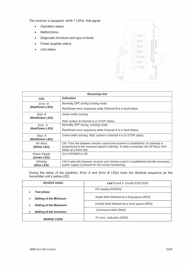
Receiving Unit LED Indication
Error B (Red/Green LED)
Stop B (Red/Green LED)
Green while running.
Red: system B channel is in STOP status. Error A
(Red/Green LED)
Stop A (Red/Green LED)
Green while running. Red: system’s channel A is in STOP status.
RF Busy (White LED)
ON if the link between remote control and receiver is established. Its intensity is proportional to the received signal’s intensity. If cable connected, the RF Busy LED blinks at a fixed rate.
Power Supply (Green LED)
On if POWER is ON .
Working (Blue LED)
ON if radio link between receiver and remote control is established and the necessary power supply is present for the correct functioning.
Joystick setup: Led ErrorA e ErrorB (COLOUR)
ON steady (GREEN)
Single blink followed by a long pause (RED)
Double blink followed by a short pause (RED)
Continuous blink (RED)
MORSE CODE TX error indication (RED)
8.7. Transmitting unit power supply
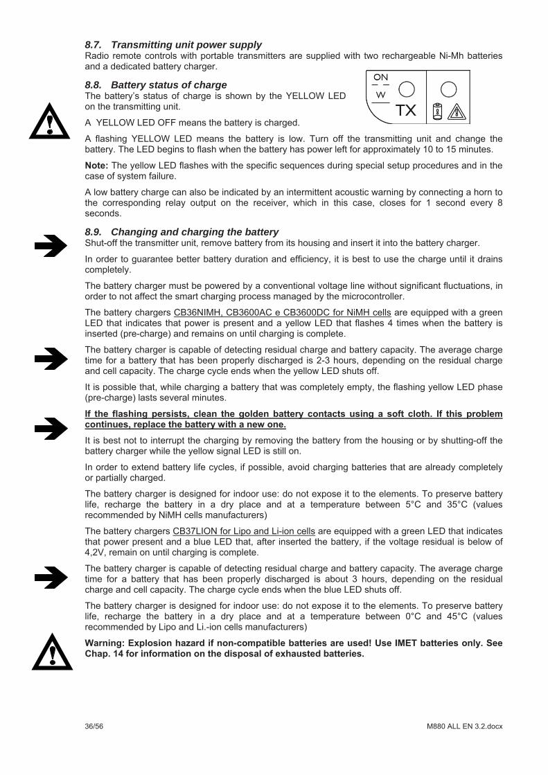
8.8. Battery status of charge
8.9. Changing and charging the battery
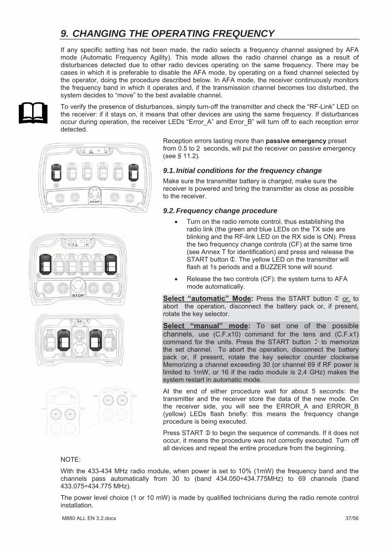
9. CHANGING THE OPERATING FREQUENCY
§
9.1. Initial conditions for the frequency change
9.2. Frequency change procedure
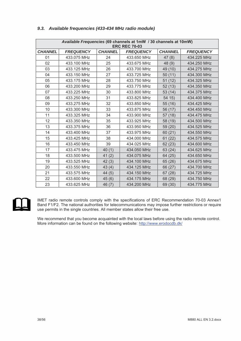
9.3. Available frequencies (433-434 MHz radio module)
Available Frequencies
CHANNEL FREQUENCY CHANNEL FREQUENCY CHANNEL FREQUENCY
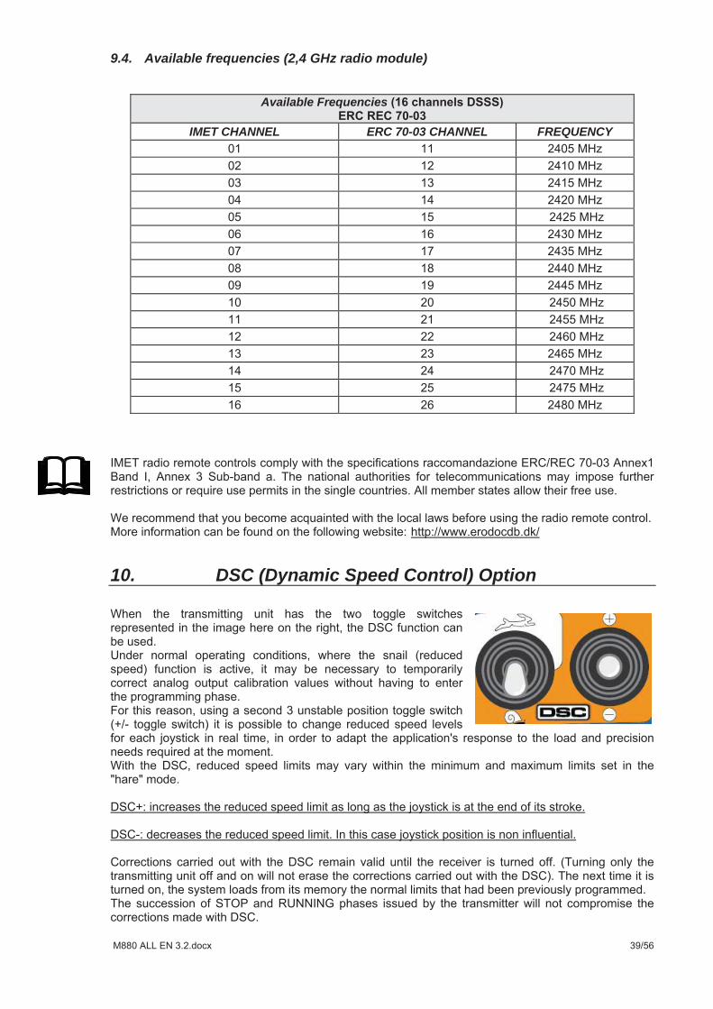
9.4. Available frequencies (2,4 GHz radio module)
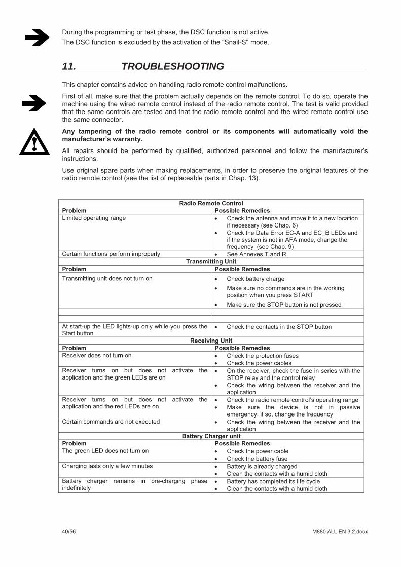
10. DSC (Dynamic Speed Control) Option
Available Frequencies
IMET CHANNEL ERC 70-03 CHANNEL FREQUENCY
11. TROUBLESHOOTING
11.1. Malfunctions in the transmitter’s STOP circuit
11.2. Passive Emergency
11.3. Technical Assistance
12. TECHNICAL SPECIFICATIONS 12.1. CE Radio module (433-434 MHz) Manufacturer IMET S.r.l. Operating frequency I.S.M. Band 433.075 434.775 MHz (1) Modulation GMSK Dev. 3 KHz Receiver sensitivity 0.22 uV 12 dB Sinad F. offset block or desensitization +/- ( 50-1000 KHz) -40 dBm F. offset block or desensitization +/- (2 MHz) -25 dBm (Limit >= -69 dBm clause 9.4
ETSI EN 300-220-1) F. offset block or desensitization +/- (10 MHz) -10 dBm (Limit >= -44 dBm clause 9.4
ETSI EN 300-220-1) Channeling 25 KHz (Half Duplex) Emission designation 25K0F1D ( 25.0kHz FSK RADIOTELEG.& DATA TRANSMISSION) Number of programmable channels 30 / 69 RF emission power <10 mW / < 1mWRange ~100 m (@10mW)Channel selection
1) Automatic Mode AFA (Automatic Frequency Agility)
2) Fixed channel Set by operator
Channeling 25K0F1D ( 25.0kHz FSK RADIOTELEG.& DATA TRANSMISSION) Transmission mode Half duplex (telegrams)Baud Rate on channel 6150 BaudHamming distance 8Error control 32 bit CRC Error non-detection probability <1.832 x 10⁻¹¹ (T.B.V.)Available pairing addresses 131072Operating temperature range of L type receivers -25°C to +60 °C (-13°F to +140°F ) Operating temperature range of H type receivers -25°C to +70 °C (-13°F to +158°F ) Operating temperature range of transmitters -25°C to +55 °C (-13°F to +131°F ) Storage temperature range -40°C to +85°C (-40°F to +185 °F) Marking CE
NOTE(1)ISM Band stands for Industrial, Scientific and Medical Band
12.2. CE, FCC, IC, ARIB radio module (2,4 GHz) Frequency band I.S.M. Band 2400-2483.5 MHzOperating frequency 2405- 2480 MHz Modulation O-QPSK MAC protocol IEEE 802.15.4 Emission designation 2M21F1DNumber of programmable channels 16 (DSSS) RF emission power <100 mW Range ~100 m (@100 mWChannel selection By the operator
Channeling 5 MHzModality of data transmission Half duplex (telegrammi)Distanza di Hamming 8Hamming distance 8Error control 32 bit CRC Error non-detection probability <1.832 x 10⁻¹¹ (T.B.V.)Available pairing addresses 131072Operating temperature range of L type receivers -25°C to +60 °C (-13°F to +140°F )
Operating temperature range of H type receivers -25°C to +70 °C (-13°F to +158°F ) Operating temperature range of transmitters -25°C to +55 °C (-13°F to +131°F ) Storage temperature range -40°C to +85°C (-40°F to +185 °F) Marking CE, FCC, IC, ARIB
NOTE(1)ISM Band stands for Industrial, Scientific and Medical Band
12.3. Transmitter Radio module specs.see § 11.1 CE Radio module Standard commands START,HORN,STOP(1)Security KEY Commands sequence that allow the
startup of remote control unit (could be disabled)
Antenna IntegratedConfiguration and diagnostic interface Radio/Computer(2)
Safety categories ISO13849-1 a) STOP circuit PLe Cat. 4
witha 5A fuse protection
b) JOYSTICK commands up to PLd Cat. 3
c) Toggle sw. and push btn commands up to PLc Cat. 2
d) Toggle sw. and push btn commands up to PLc Cat. 1
Status indicator and error LEDs Green: power on Yellow: diagnostic Blue: LINK Status
Commands / Outputs 56 Max (3) Numbers of panel indicators 16 Max (4)Number of ON/OFF commands 56 Max (5)Number of analog commands 16 (19) Max (5) Max Number of UMFS commands up to PL d, Cat. 3 16 (6) (ISO 13849-1:2006 6.2.6
architecture)
Display Graphic backlight LCD a) 102x64 pixels monochromatic b) 128x64 pixels monochromatic c) 160x64 pixels monochromatic d) QVGA 3,5” color TFT (optional)
Beeper internal Buzzer Backlit panel optional Serial Lines
RS232 o RS485 CAN
OPTIONS Wired control cable Lean-angle control
Dead man functionSafety-ringIRProxy
THOR2, ZEUS2, KRON, ARES2, G4L, G4S Power supply 3,6 VDC
<160 mABattery Ni-MH 3,6VBattery autonomy ~22 ore (@ 20°C)Low Battery notification time 15 minutesOperating temperature range -25°C to +55 °C (-13°F to +131°F ) Storage temperature range -40°C to +85°C (-40°F to +185 °F) Transmitters housing material UL94 HB Transmitters housing material G4L GFK Casing protection degree IP65
Dimensions without LCD display M880 THOR2 295x180x160 mm L.W.H.)Dimensions with LCD display M880 THOR2 295x250x165 mm L.W.H.)Weight (battery included) M880 THOR2
Dimensions without LCD display M880 ZEUS2 205x150x150 mm (L.W.H.)Dimensions with LCD display M880 ZEUS2 205x205x150 mm (L.W.H.)Weight (battery included) M880 ZEUS2
Dimensions without LCD display M880 KRON 180x107x160 mm (L.W.H.)Weight (battery included) M880 KRON
Dimensions M880 ARES2 (L.W.H.)Weight (battery included)ARES2 E /C M880 ARES2 E/C
Dimensions M880 G4L (L.W.H.)Weight (battery included) M880 G4L
Dimensions M880 G4S 265x185x165 mm (L.W.H.)Weight (battery included) M880 G4S
WAVE2 Power supply 3,7 VDC
80 mA (300 mA with back light on)Battery Li-Ion 3,7VBattery autonomy ~25 ore (@ 20°C)Low Battery notification time 15 minutesOperating temperature range -25°C to +55 °C (-13°F to +131°F ) Storage temperature range -40°C to +85°C (-40°F to +185 °F) Transmitters housing material UL94 HB Casing protection degree IP65
Dimensions WAVE2 S6/S8 mm Weight (battery included) M880 WAVE2 S6/S8
Dimensions WAVE2 L10/L12 Weight (battery included) M880 WAVE2 S6/S8
Note: (1)Emergency stop mushroom-head pushbutton with turn to reset
(2)The installer using IMET equipment:
Can make a copy of data stored in the remote radio control
Can examine the radio control history for errors/faults sequence, operating hours and other functions described in the equipment manual Can do the setup of analog commands from a PC (minimum, maximum, speed ramps) and of function commands (interlocks, latching commands, etc.)
(3)Our system is highly flexible in that it allows multiple input configurations, which can satisfy customer requirements: in case of need, an analog input can convert to a digital one and, a digital input can be used as a digital output (e.g. a LED). (4)Every LED counts as a digital input. It is possible to increase that number using a special board. (5)Safety categories ISO13849-1 : Some configuration examples:
55 ON/OFF commands, 0 analog commands, 0 LED 48 (@ PLc Cat. 1), 7 (@ PLb Cat. b) (16 JOYSTICK, 16 Digital x JOYSTICK), 7 auxiliary 16 (@PLd,Cat. 3), 7 auxiliary (@ PLb Cat b) 16 analog inputs, 16 digital inputs, 7 auxiliary: 16AN+16DIG (@PLc Cat1), 7 auxiliary (@PLb Cat b)
(6)UMFS= Unintended Movement From Standstill
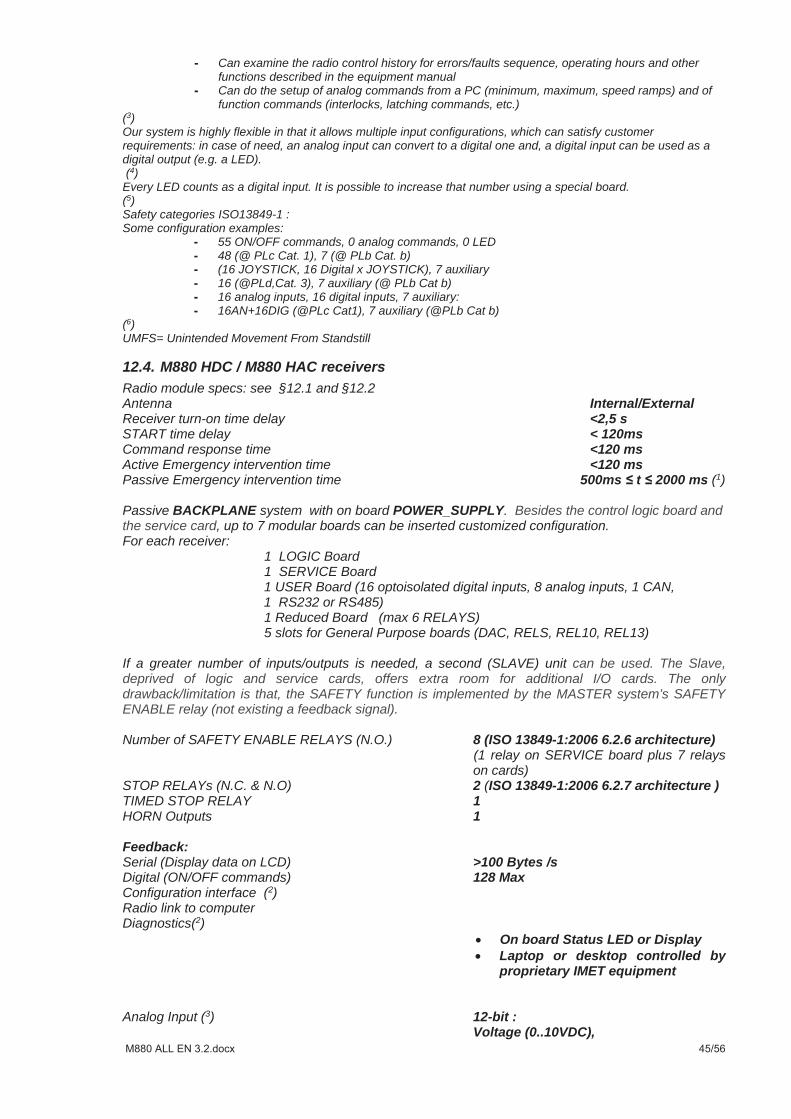
12.4. M880 HDC / M880 HAC receivers Radio module specs: see §12.1 and §12.2 Antenna Internal/External Receiver turn-on time delay <2,5 sSTART time delay < 120msCommand response time <120 msActive Emergency intervention time <120 ms Passive Emergency intervention time 500ms t 2000 ms (1)
Passive BACKPLANE system with on board POWER_SUPPLY. Besides the control logic board and the service card, up to 7 modular boards can be inserted customized configuration. For each receiver:
1 LOGIC Board 1 SERVICE Board 1 USER Board (16 optoisolated digital inputs, 8 analog inputs, 1 CAN, 1 RS232 or RS485) 1 Reduced Board (max 6 RELAYS) 5 slots for General Purpose boards (DAC, RELS, REL10, REL13)
If a greater number of inputs/outputs is needed, a second (SLAVE) unit can be used. The Slave, deprived of logic and service cards, offers extra room for additional I/O cards. The only drawback/limitation is that, the SAFETY function is implemented by the MASTER system’s SAFETY ENABLE relay (not existing a feedback signal).
Number of SAFETY ENABLE RELAYS (N.O.) 8 (ISO 13849-1:2006 6.2.6 architecture) (1 relay on SERVICE board plus 7 relays on cards)
STOP RELAYs (N.C. & N.O) 2 (ISO 13849-1:2006 6.2.7 architecture )TIMED STOP RELAY 1HORN Outputs 1 Feedback: Serial (Display data on LCD) >100 Bytes /s Digital (ON/OFF commands) 128 Max Configuration interface (2)Radio link to computer Diagnostics(2)
On board Status LED or Display Laptop or desktop controlled by proprietary IMET equipment
Analog Input (3) 12-bit : Voltage (0..10VDC),
Current (4/20mA, 0/20mA)Digital 0/24 VDC optoisolated
Outputs:(4)ON/OFF 128 max:
Relay (AC e DC); MOSFET (DC)
ANALOG 32 max: Proportional (PWM) Analog (current) Analog (voltage)
Serial communication interfaces: RS232 or RS485 (115200 Baud max) CAN_Bus (ID 11-29 bit) CANOpen (ID 11-29 bit) Other types on request
Power supply (AC type) 45-240Vac, max 1.1A@45Vac, 45VA
Power supply (AC/DC type ) 11-30Vdc, max 4A@12Vdc, 44W / 24 Vac (50-60 Hz), max 2,8A , 68VA
Operating temperature range -25°C to +70°C (-13°F to +158 °F) Storage temperature range -40°C to +85°C (-40°F to +185 °F) Housing material UL94 V0 5VA, UL 746C (f1) Casing protection degree IP66 Dimensions 205x130x280 mm (L.W.H.) Weight (standard configuration) 3,5 Kg Mounting brackets minimum load (6) 120N
NOTE (1): In referring to EN 60204-32 clause 9.2.7.3, in base to the analyzing risks the installer or the manufacturer of the machine can be set, or ask to be set by specific IMET interface, passive emergency time from 500 to 2000ms. NOTE (2): Both, the receiver and the diagnosis configurations can be made with an IMET-dedicated interface by radio link. This technique is useful in all those cases when the receiver is not easily accessible, or when you do not want to open the case to access the data port.NOTA (3): Inputs are managed by the user card SUH. The technical data can be found on the SUH’s data sheet.NOTE (4): Electrical features of COMMANDS. The number shown is the one managed by the logic board; the real number could be limited by physical constraints (i.e. on the mother board it is not possible to mount 4 DAC board for 32 analog outputs) NOTE (5): For versions that do not contemplate the presence of the DAC board, it is possible to have a supply voltage having an extended range NOTE (6): See section 4.2.10 of the Directive IEC 60950-1 2007-02 Wall or Ceiling Mounted Equipment.
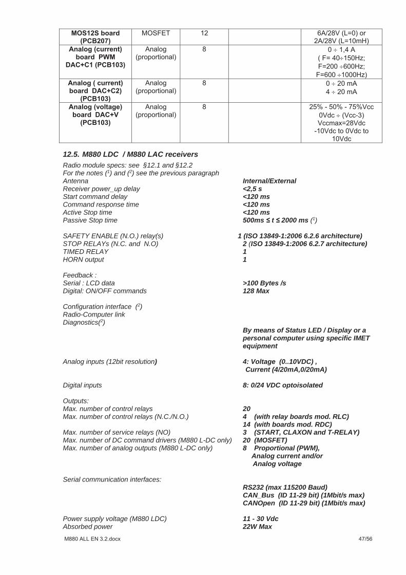
12.5. M880 LDC / M880 LAC receivers Radio module specs: see §12.1 and §12.2 For the notes (1) and (2) see the previous paragraph Antenna Internal/External Receiver power_up delay <2,5 sStart command delay <120 msCommand response time <120 msActive Stop time <120 ms Passive Stop time 500ms t 2000 ms (1)
SAFETY ENABLE (N.O.) relay(s) 1 (ISO 13849-1:2006 6.2.6 architecture)STOP RELAYs (N.C. and N.O) 2 (ISO 13849-1:2006 6.2.7 architecture)TIMED RELAY 1HORN output 1
Feedback : Serial : LCD data >100 Bytes /s Digital: ON/OFF commands 128 Max
Configuration interface (2)Radio-Computer link Diagnostics(2)
By means of Status LED / Display or a personal computer using specific IMET equipment
Analog inputs (12bit resolution) 4: Voltage (0..10VDC) ,
Current (4/20mA,0/20mA)
Digital inputs 8: 0/24 VDC optoisolated
Outputs: Max. number of control relays 20Max. number of control relays (N.C./N.O.) 4 (with relay boards mod. RLC) 14 (with boards mod. RDC)Max. number of service relays (NO) 3 (START, CLAXON and T-RELAY)Max. number of DC command drivers (M880 L-DC only) 20 (MOSFET)Max. number of analog outputs (M880 L-DC only) 8 Proportional (PWM),
Analog current and/or Analog voltage
Serial communication interfaces: RS232 (max 115200 Baud) CAN_Bus (ID 11-29 bit) (1Mbit/s max) CANOpen (ID 11-29 bit) (1Mbit/s max)
Power supply voltage (M880 LDC) 11 - 30 Vdc Absorbed power 22W Max
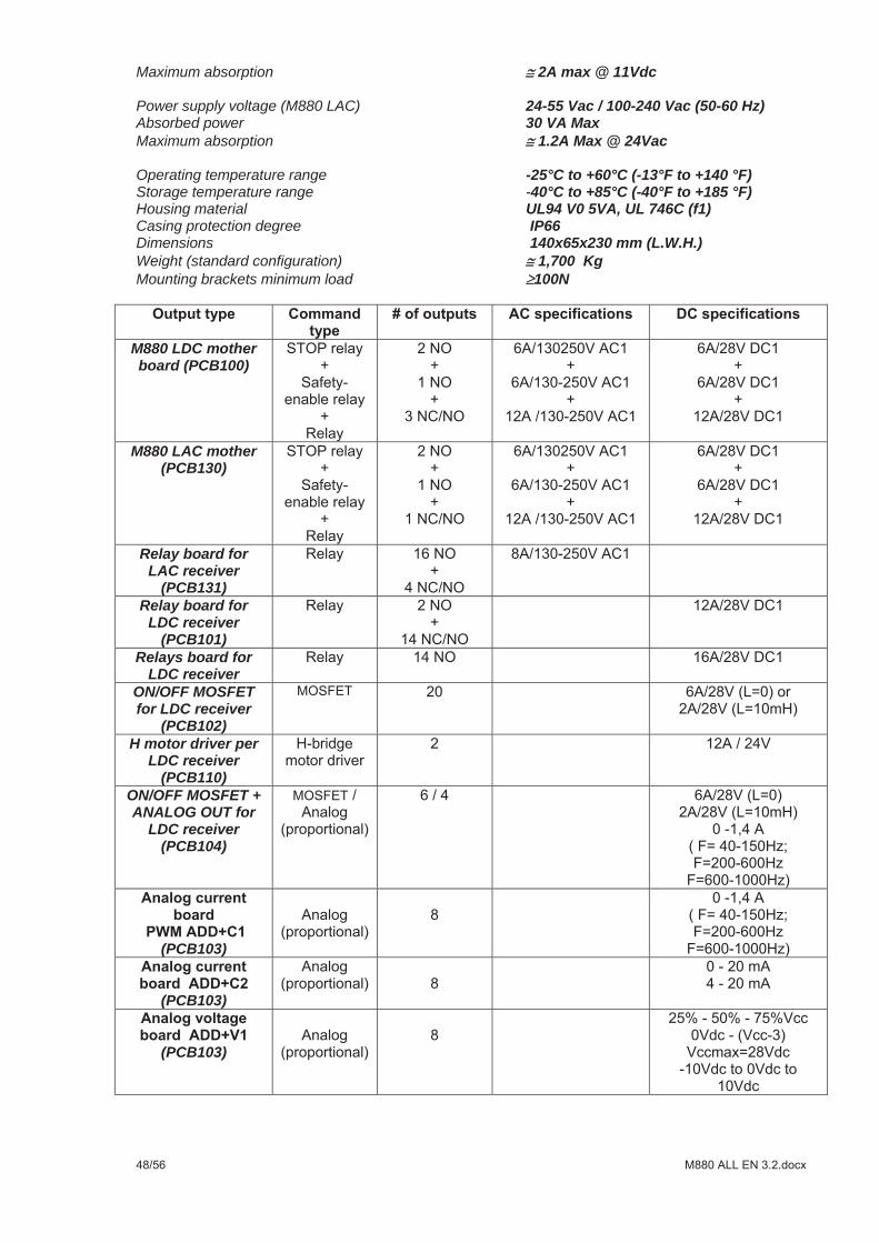
Maximum absorption 2A max @ 11Vdc Power supply voltage (M880 LAC) 24-55 Vac / 100-240 Vac (50-60 Hz) Absorbed power 30 VA MaxMaximum absorption 1.2A Max @ 24Vac Operating temperature range -25°C to +60°C (-13°F to +140 °F) Storage temperature range -40°C to +85°C (-40°F to +185 °F) Housing material UL94 V0 5VA, UL 746C (f1) Casing protection degree IP66 Dimensions 140x65x230 mm (L.W.H.) Weight (standard configuration) 1,700 Kg Mounting brackets minimum load 100N
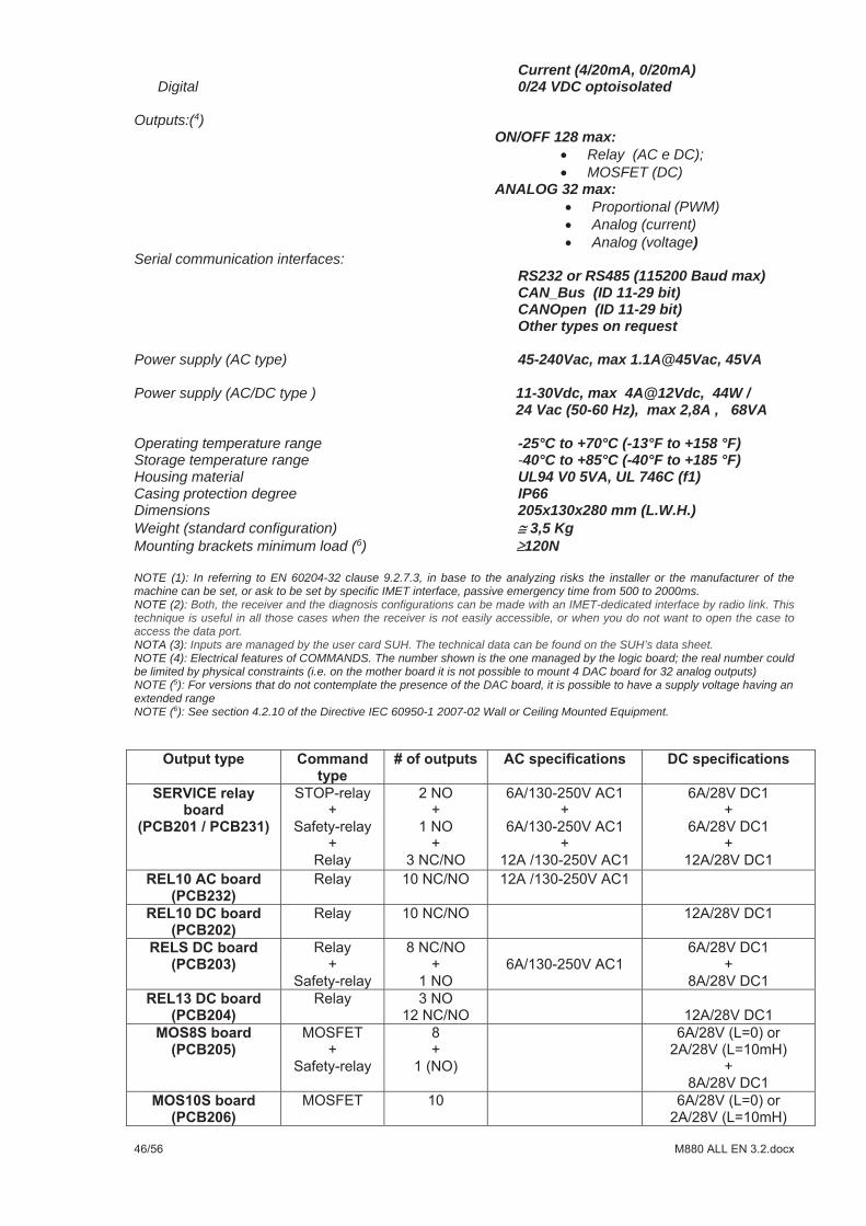
M880 LDC mother board (PCB100)
M880 LAC mother (PCB130)
Relay board for LAC receiver
(PCB131) Relay board for
LDC receiver (PCB101)
Relays board for LDC receiver
ON/OFF MOSFET for LDC receiver
(PCB102) H motor driver per
LDC receiver (PCB110)
ON/OFF MOSFET + ANALOG OUT for
LDC receiver (PCB104)
(PCB103)
(PCB103)
(PCB103)
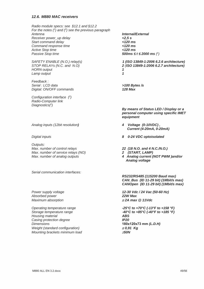
12.6. M880 MAC receivers
Radio module specs: see §12.1 and §12.2 For the notes (1) and (2) see the previous paragraph Antenna Internal/External Receiver power_up delay <2,5 sStart command delay <120 msCommand response time <120 msActive Stop time <120 ms Passive Stop time 500ms t 2000 ms (1)
SAFETY ENABLE (N.O.) relay(s) 1 (ISO 13849-1:2006 6.2.6 architecture)STOP RELAYs (N.C. and N.O) 2 (ISO 13849-1:2006 6.2.7 architecture)HORN output 1 Lamp output 1
Feedback : Serial : LCD data >100 Bytes /s Digital: ON/OFF commands 128 Max
Configuration interface (2)Radio-Computer link Diagnostics(2)
By means of Status LED / Display or a personal computer using specific IMET equipment
Analog inputs (12bit resolution) 4 Voltage (0-10VDC) ,
Current (4-20mA, 0-20mA)
Digital inputs 8 0-24 VDC optoisolated
Outputs: Max. number of control relays 22 (18 N.O. and 4 N.C./N.O.) Max. number of service relays (NO) 2 (START, LAMP) Max. number of analog outputs 4 Analog current (NOT PWM )and/or
Analog voltage
Serial communication interfaces: RS232/RS485 (115200 Baud max) CAN_Bus (ID 11-29 bit) (1Mbit/s max) CANOpen (ID 11-29 bit) (1Mbit/s max)
Power supply voltage 12-30 Vdc / 24 Vac (50-60 Hz) Absorbed power 22W MaxMaximum absorption 2A max @ 11Vdc Operating temperature range -25°C to +70°C (-13°F to +158 °F) Storage temperature range -40°C to +85°C (-40°F to +185 °F) Housing material ABS Casing protection degree IP20 Dimensions (L.D.H) Weight (standard configuration) 0,91 Kg Mounting brackets minimum load 50N
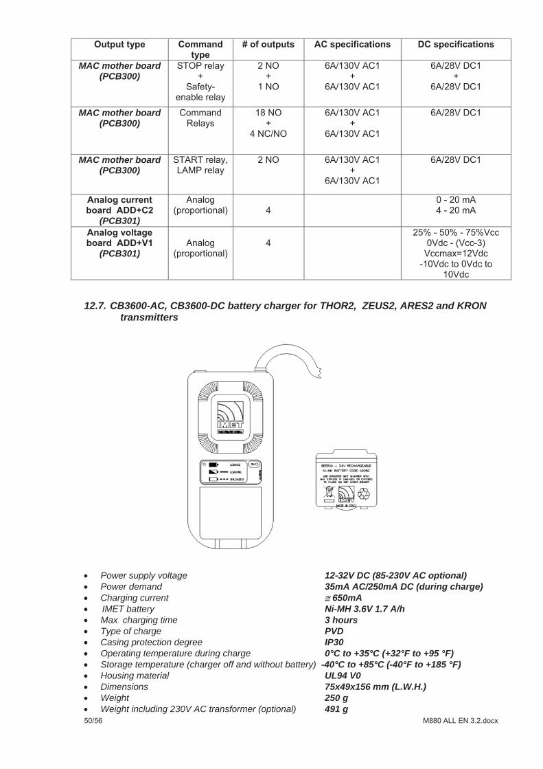
MAC mother board (PCB300)
MAC mother board (PCB300)
MAC mother board (PCB300)
(PCB301)
(PCB301)
12.7. CB3600-AC, CB3600-DC battery charger for THOR2, ZEUS2, ARES2 and KRON transmitters
Power supply voltage 12-32V DC (85-230V AC optional)Power demand 35mA AC/250mA DC (during charge)Charging current 650mA
IMET battery Ni-MH 3.6V 1.7 A/hMax charging time 3 hoursType of charge PVDCasing protection degree IP30Operating temperature during charge 0°C to +35°C (+32°F to +95 °F)Storage temperature (charger off and without battery) -40°C to +85°C (-40°F to +185 °F)Housing material UL94 V0Dimensions 75x49x156 mm (L.W.H.)Weight 250 gWeight including 230V AC transformer (optional) 491 g
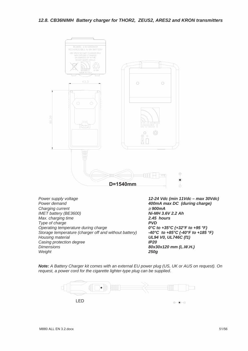
12.8. CB36NIMH Battery charger for THOR2, ZEUS2, ARES2 and KRON transmitters
Power supply voltage 12-24 Vdc (min 11Vdc – max 30Vdc) Power demand 400mA max DC (during charge) Charging current 900mAIMET battery (BE3600) Ni-MH 3.6V 2.2 Ah Max. charging time 2.45 hours Type of charge PVDOperating temperature during charge 0°C to +35°C (+32°F to +95 °F)Storage temperature (charger off and without battery) -40°C to +85°C (-40°F to +185 °F) Housing material UL94 V0, UL746C (f1) Casing protection degree IP20Dimensions 80x30x120 mm (L.W.H.)Weight 250g Note: A Battery Charger kit comes with an external EU power plug (US, UK or AUS on request). On request, a power cord for the cigarette lighter-type plug can be supplied
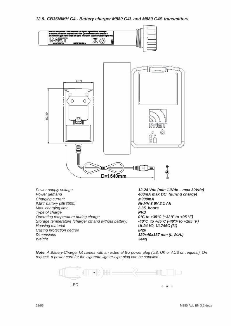
12.9. CB36NIMH G4 - Battery charger M880 G4L and M880 G4S transmitters
Power supply voltage 12-24 Vdc (min 11Vdc – max 30Vdc) Power demand 400mA max DC (during charge) Charging current 900mAIMET battery (BE3600) Ni-MH 3.6V 2.1 Ah Max. charging time 2.35 hours Type of charge PVDOperating temperature during charge 0°C to +35°C (+32°F to +95 °F)Storage temperature (charger off and without battery) -40°C to +85°C (-40°F to +185 °F) Housing material UL94 V0, UL746C (f1) Casing protection degree IP20Dimensions 120x40x137 mm (L.W.H.)Weight 344g Note: A Battery Charger kit comes with an external EU power plug (US, UK or AUS on request). On request, a power cord for the cigarette lighter-type plug can be supplied
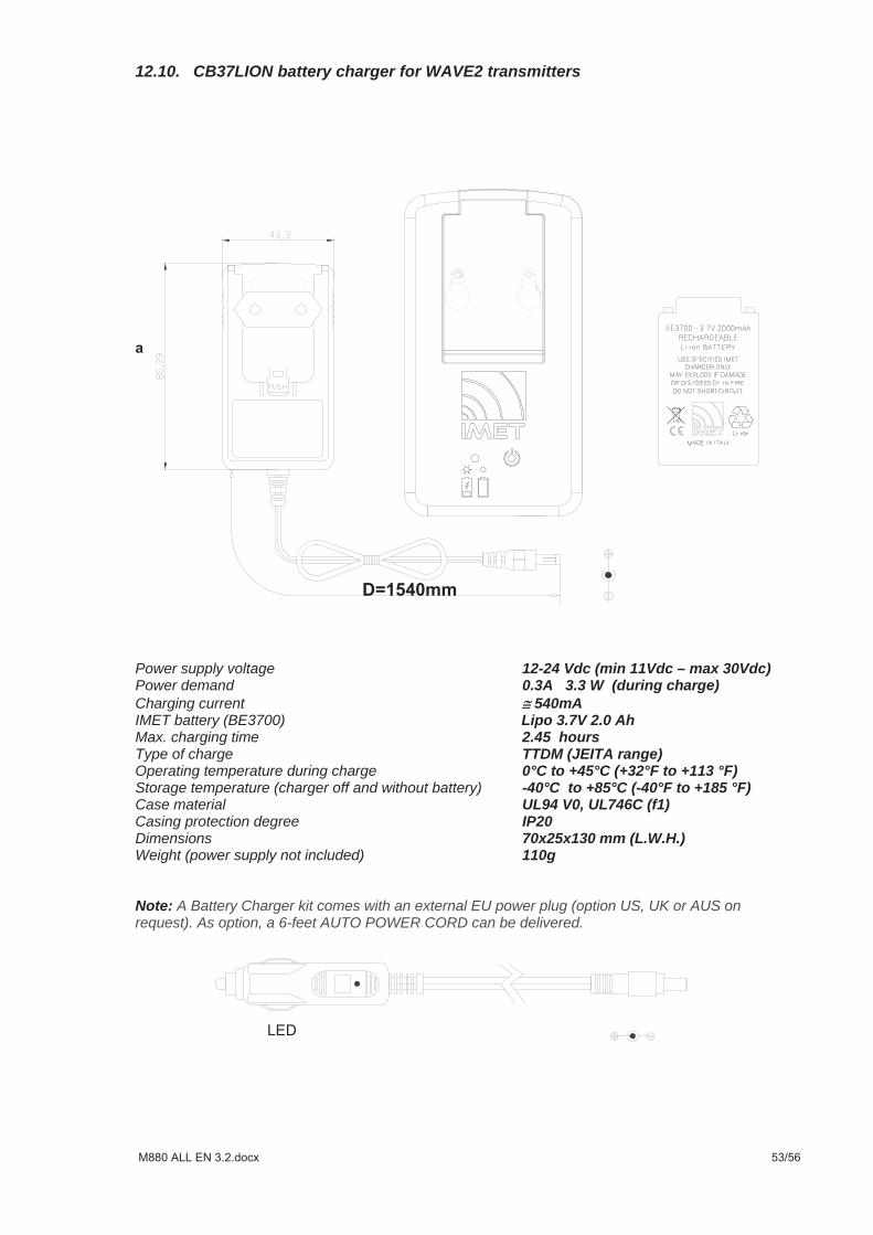
12.10. CB37LION battery charger for WAVE2 transmitters
Power supply voltage 12-24 Vdc (min 11Vdc – max 30Vdc) Power demand 0.3A 3.3 W (during charge) Charging current 540mAIMET battery (BE3700) Lipo 3.7V 2.0 AhMax. charging time 2.45 hours Type of charge TTDM (JEITA range) Operating temperature during charge 0°C to +45°C (+32°F to +113 °F)Storage temperature (charger off and without battery) -40°C to +85°C (-40°F to +185 °F) Case material UL94 V0, UL746C (f1) Casing protection degree IP20Dimensions 70x25x130 mm (L.W.H.)Weight (power supply not included) 110g
Note: A Battery Charger kit comes with an external EU power plug (option US, UK or AUS on request). As option, a 6-feet AUTO POWER CORD can be delivered.
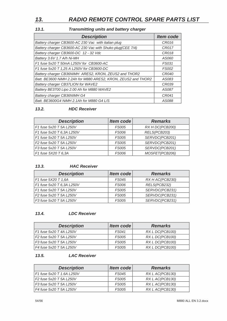
13. RADIO REMOTE CONTROL SPARE PARTS LIST 13.1. Transmitting units and battery charger
Description Item code Battery charger CB3600-AC 230 Vac with italian plug CR016 Battery charger CB3600-AC 230 Vac with Shuko plug(CEE 7/4) CR017 Battery charger CB3600-DC 12 - 32 Vdc CR018 Battery 3.6V 1.7 A/h Ni-MH AS060 F1 fuse 5x20 T 50mA L250V for CB3600-AC FS031 F1 fuse 5x20 T 1,25 A L250V for CB3600-DC FS002 Battery charger CB36NIMH ARES2, KRON, ZEUS2 and THOR2 CR040 Batt. BE3600 NiMH 2.2Ah for M880 ARES2, KRON, ZEUS2 and THOR2 AS083 Battery charger CB37LION for WAVE2 CR039 Battery BE3700 Lipo 2.00 Ah for M880 WAVE2 AS087
Battery charger CB36NIMH G4 CR041 Batt. BE3600G4 NiMH 2.1Ah for M880 G4 L/S AS088
13.2. HDC Receiver
Description Item code Remarks F1 fuse 5x20 T 5A L250V FS005 RX H DC(PCB200) F1 fuse 5x20 T 6,3A L250V FS006 RELS(PCB203) F1 fuse 5x20 T 5A L250V FS005 SERVDC(PCB201) F2 fuse 5x20 T 5A L250V FS005 SERVDC(PCB201) F3 fuse 5x20 T 5A L250V FS005 SERVDC(PCB201) F1 fuse 5X20 T 6,3A FS006 MOSFET(PCB206)
13.3. HAC Receiver
Description Item code Remarks F1 fuse 5X20 T 1,6A FS045 RX H AC(PCB230) F1 fuse 5x20 T 6,3A L250V FS006 RELS(PCB232) F1 fuse 5x20 T 5A L250V FS005 SERVDC(PCB231) F2 fuse 5x20 T 5A L250V FS005 SERVDC(PCB231) F3 fuse 5x20 T 5A L250V FS005 SERVDC(PCB231)
13.4. LDC Receiver
Description Item code Remarks F1 fuse 5x20 T 4A L250V FS041 RX L DC(PCB100) F2 fuse 5x20 T 5A L250V FS005 RX L DC(PCB100) F3 fuse 5x20 T 5A L250V FS005 RX L DC(PCB100) F4 fuse 5x20 T 5A L250V FS005 RX L DC(PCB100)
13.5. LAC Receiver
Description Item code Remarks F1 fuse 5x20 T 1.6A L250V FS045 RX L AC(PCB130) F2 fuse 5x20 T 5A L250V FS005 RX L AC(PCB130) F3 fuse 5x20 T 5A L250V FS005 RX L AC(PCB130) F4 fuse 5x20 T 5A L250V FS005 RX L AC(PCB130)
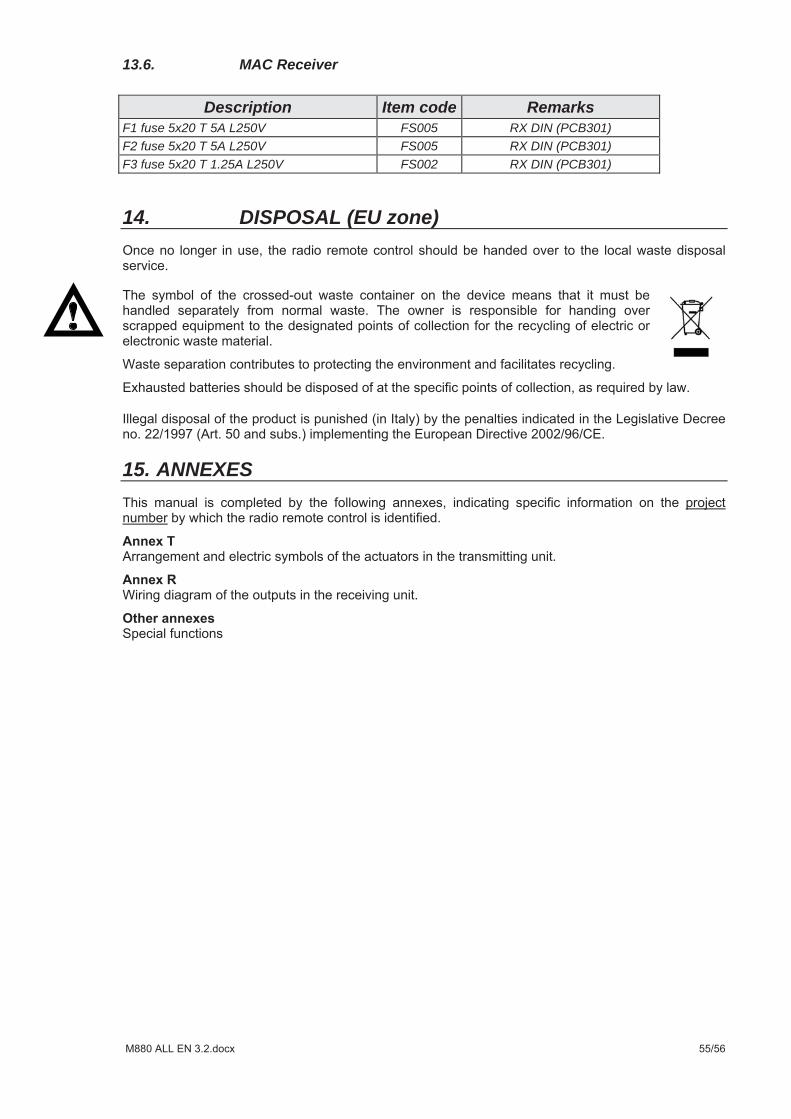
13.6. MAC Receiver
Description Item code Remarks F1 fuse 5x20 T 5A L250V FS005 RX DIN (PCB301) F2 fuse 5x20 T 5A L250V FS005 RX DIN (PCB301) F3 fuse 5x20 T 1.25A L250V FS002 RX DIN (PCB301)
14. DISPOSAL (EU zone)
15. ANNEXES