radio engineering mobile radio engineering and...
TRANSCRIPT

BELL SYSTEM PRACTICESAT&TCo Standard
SECTION 940-220-105Issue 1, August 1971
RADIO ENGINEERING
MOBILE RADIO
ENGINEERING AND IMPLEMENTATION METHOD SYSTEM FOR
150-MEGAHERTZ BELLBOY@
CONTENTS PAGE
1. GENERAL . . . .
A. System Operation
B. System Features
2. SYSTEM COMPONENTS
A. Radio Transmitter
B. Radio Receiver .
C. Control Terminal
3. SYSTEM PLANNING
A.
B.
c.
D.
E.
F.
G.
H.
System Design .
. . . . . . .
. . . . . . .
. . . . . *.
. . . . . .
.* ..* ● ✎
✎ ✎ ✎ ✎ ✎ ✎ ✎
✎ ✎ ✎ ✎ ✎ ✌✎
✎ ✎ ✎ ✎ ✎ ● ✎
✎ ✎ ✎ ✎ ✎ ✎ ✎
Transmitter Site Determination . .
Channel Selection . . . . . . .
Cochannel Operation . . . . . .
Radio Interference . . . . . . .
Frequency and Phase Requirements
Interface Considerations . . , .
Interconnection Arrangements . .
4. LICENSEAPPLICATION PROCEDURES .
5. EQUIPMENT ENGINEERINGcoNswRAmOw. . . . . . . . . . .. *.*
6. TESTEQUIPMENT . . . . . . . .
7. SYSTEM ACCEPTANCE TESTS . . . .
1
1
2
3
3
5
5
5
6
11
12
12
13
15
15
15
16
16
17
17
CONTENTS PAGE
8. REFERENCES . . . . . . . . ..17
1. GENERAL
1.01 This section provides overall engineeringinformation and other considerations for the
150-MHzBELLBOY personal signaling system. Thesystem permits a customer to be selectively called,while he is away from his own telephone, by meansof a small pocketarried radio receiver.
A. System Opemtion
1.02 The overall system employs direct customerdialing and FM radio transmission. Two
radio frequency assignments, 152.84 and 158.10MHz, have been authorized by the FederalCommunications Commission (FCC) for exclusiveone-way signaling by wire-line common carriers.One radio frequency is required per system witha maximum of two per serving area.
1.03 Figure 1 illustrates a typical setup for aBELLBOY call. The BELLBOY customer
carries a pocket receiver which is assigned aseven-digit telephone number. A person desiringto contact the customer dials the BELLBOY numberfrom any telephone. From the local office thecall is routed over a tandem or direct trunk tothe central office serving the BELLBOY controlterminal. The control terminal translates the dialednumber into a three-frequency signaling code whichis transmitted over wire-line facilities to frequencymodulate one or more transmitters.
1.04 A complete call consists of sending thesignaling code three times at intervals of
approximately 30 seconds. During the 30-secondintervals calls to other customers may also betransmitted. A distinctive “tinkle tone” and a
@ AmericanTelephoneandTelegraphCompany,1971Printedin U.S.A. Page 1

SECTION 940-220-105
\ %
~\
QQ BELLBOY
R: Cfl VER
iii
* A
Ii——l TFFFil
BfLLBOY I !
NuMBCR BELLBOY
DIALEDCONTROL
TERMINAL L.PBCLLBOY
TRANSMITTER
Fig. l—Typical Setup far a BELLBOY Call
voice announcement stating that the call will betransmitted is returned to the caller. If thenumber is not a working one, the call is transferredto intercept where an appropriate report is giventhe calling party. When the signal reaches theBELLBOY receiver, it causes the set to emit analerting tone indicating that the customer shouldtake some prearranged action such as call his officeor his home. Depressing a small reset button onthe receiver silences the tone and conditions thereceiver for the next call. The alerting tone willautomatically silence in about 15 seconds if thereset button is not operated.
B. System Features
1.05 The system consists principally of a centraloffice control terminal, 1 to 20 radio
transmitters, and up to 3200 BELLBOY receivers.
1.06 Principal operating features of the systeminclude call storage, numberto-tone translation%
simultaneous signaling, functional voiceannouncement,and multitransmitter operation.
1.o7 The first three digits of the telephonenumber direct the call to the control terminal.
The last four digits are pulsed into the terminalwhere they are processed and stored during thethree transmissions of the call. These digits are
V]w
/$
,=-
/==----
[,
translated into a threefrequency signaling code inthe audio-frequency range of 500 to 1000 Hz. Thethree frequencies of the code are transmittedsimultaneously by the radio transmitters. The threetones which modulate the transmitk~ carriers willsignal only the receiver responsive to that particularcode. There are 3200 usable signaling codes derivedfrom 32 audio-frequency tones.
1.06 To discourage use of BELLBOY units inother BELLBOYsystems outside the customer’s
home area, a series of tone-versus-telephone-numbertranslation plans have been devised. Thus, differenttones are assigned to a particular BELLBOYnumber (last 4 digits) in various systems. Changingthe order in which the tone generators are pluggedinto the control terminal provides a convenientmeans of establishing different translation plans.Eight such plans, A through H, are discussed inSection 407-207-100 and are assigned on a randomnationwide basis with a separation of 100 to 200miles between like plans on the same radio frequency.
1.09 In addition to voice announcements for callcompletion, provision is made for a trouble
announcement and periodic station identification.Normally, a reorder tone is returned to thesubscriber when the control terminal is in trouble.However, a key operation inserts the troubleannouncement when trouble is sufficient to put
Page 2

1SS1, SECTION 940-220-105
the system out of service for an extended period.Periodic station identification using InternationalMorse Code is accomplished by means of a timingcircuit. The timing interval begins at the firsttransmission and inserts the station identificationafter 30 minutes elapsed time or as soon thereafteras the radio transmitters become idle.
2. SYSTEM COMPONENTS
A. Radio Transmitter
2.o1 The KS-20429 Radio Transmitter, shown inFig, 2, employs frequency modulation, and
has an output power variable from 50 to 150 watts,a precision crystal oscillator, harmonic filters, andmonitors to check for the presence of carrier andmodulation. Alarms at the control terminal indicateloss of carrier or modulation. Monitoring is necessaryinasmuch as a failure on a one-way system mightnot be detected for an extended period or until alarge number of customers had missed calls.optional features inchde RF isolatcm and arrangementsfor outdoor installation. Each transmitter interfaceswith a Western Electric Company trunk terminatingunit to provide for interconnection to alarm andcontrol facilities. Sections of the 407-201 PlantSeries furnish detailed information on this transmitter.
Page 3

I
SECTION 940-220-105
‘o o J
—.. *
—
— -—.— ._._a., .
Fig. 2—150-MHz BELLBOY Transmitter
Page 4

1SS1, SECTIGN 940-220-105
KS-20429 Transmitter Specifications
Manufacturer — Motorola, Inc.Type acceptance number — CC3058Frequency stability — +0.0001 percent perYRPower output — 50 to 150 W (adjustable)Weight — 500 lbsCabinet size — 5 x 2 x 2 ftAC power — 117 Vac at 10 AFrequency range — 150 to 160 MHzMaximum deviation — &5 kHzMaximum input power — no isolator — 280 W
one isolator — 310 Wtwo isolators — 340 W
B. Radio Receiver
2.o2 The KS-20432 Radio Receiver, which maybe carried in the pocket or clipped to a bel~,
is shown in Fig. 3. It is a miniaturized, solid-state,single conversion, FM superheterodyne type, whichoperates in low signal-to-noise environments. Itconsists of an RF stage, a mixer stage, four 6-kHzIF stages, a detector stage, a decoder, and a sourceof alerting tone. Nominal receiver sensitivity (8azimuthal position body average) is 20 uV/m orequivalent to – 126 dBW on a quarter-wave whipantenna per Ref(2). Sections of the 407-204 PlantSeries furnish detailed information on this receiver.
Fig. 3-1 50-MHz BELLBOY Receiver
KS-20432 Receiver Specifications
Manufacturer — Motorola, Inc.Sensitivity (8 position body average) — 20 uV/m
or – 126 dBWWeight (with battery) — 9.25 ozVolume — 10.8 cu inDecoder — contactless reedSounder frequency — 2 kHzSounder amplitude — 78 dB SPL min at 13 inSounder time-out — 15 SOperating time (on a single charge) — 10 HRCharging time — 12 HREstimated battery life — 1 YR
C. Control Terminal
2.02 The control terminal translates the last fourdigits of the dialed BELLBOY number to
the signaling code, controls the radio transmitters,verifies that a working number has been dialed,collates and sequences the signals to be transmitted,returns tone and voice announcements to thesubscriber, transfers invalid calls to intercept, andmakes periodic station identification announcements.
2.04 The control terminal has a maximum capacityof 3200 customers in number blocks 1000
through 1999, 2100 through 2699, 3000 through3999, and 4100 through 4699. A fully equippedcontrol terminal consists of six equipment bays.Four bays comprised of the transmitter controlbay, tone supply bay, common control bay, andannouncement bay contain all of the commonequipment and are always required. They canserve up to a maximum of 1200 customers. Thefirst and second supplemental bays increase thecapacity to 2400 and 3200 customers, respectively.Section 407-200-100 furnishes detailed informationon the control terminal.
2.05 Metallic pairs between the control terminaland radio transmitters provide the tone
signaling path and two dc paths for transmitteralarms and remote control. Delay equalization isrequired on these facilities in multitransmittersystems. Loss equalization across the signalingband may also be required.
3. SYSTEM PLANNING
3.o1 Planning a BELLBOY system requiresconferring with all departments involved with
Page 5

fI SECTION 940-220-105I
the service in order to arrive at a system designthat will satisfy as many of the company requirementsas possible for the particular locality involved. Theitems to be considered should include the following
(a) Marketing: Area to be served. Marketpotential, initial system requirements, customer
equipment estimates, growth estimates, promotionalprograms, and customer education.
(b) Rates BELLBOY rates including multiplereceivers, extra battery, extra charger, etc.
(c) plant: Maintenance of BELLBOY receivers,transmitters, and terminal. Establishing
method of handling trouble reports and repairservice. Receiver repair can be handled eitherby (1) Western Electric Company shop, (2)Telephone Company shop, or (3) manufacturer’srepair contract. Operation and maintenanceinstructions.
(d) Engineering: Estimated equipmentrequirements and costs. Installation, test,
and service dates, FCC matters, Western ElectricCompany schedules, and Engineering practices.
(e) ZYat.77CEstimated traffic loads. Requirementsfor number of incoming trunk registers
(ITR). Storage circuits and number check circuits.BELLBOY number assignments. Interceptarrangements.
A. System Design
3.02 For a user of the BELLBOY service, theonly meaningful measure of service is the
reliability with which he is signaled. This reliabilityvaries with the location of the user, who may beoutdoors in an open area, or in the basement of aconcrete and steel building. It is somewhat difficult,in such a service, to define an adequate criterionof service. A system-wide average probability ofsuccess is not appropriate where extreme variabilitycan cause some users to have virtually perfectservice and others, who work in certain buildings,to have consistently poor service. It is preferablebecause of these factors to consider the distributionof service grade, that is, the percentage of buildingsenjoying better than any given grade of service.
3.o3 The overall design objective for engineeringBELLBOY service is to provide a reliable
alerting signal inside buildings within the prescribed
coverage area. Street coverage, which is alwaysassured in the primary service area, will extendwell out and beyond that of the primary servicearea. The percentage of buildings exceeding agiven signaling reliability at the boundary of theprimary service area may be estimated from thecurves in Fig. 4. The following assumptions aremade:
Five classifications of buildings, by size,location, and structure, were used to arriveat a cumulative total percentage. Thesewere intended to typify buildings in whichBELLBOY users would be found.
An allowance for the diversity advantageresulting from the use of two transmittersis assumed.
Signaling reliability is computed for theground floor of the assumed types ofbuildings.
No increase in reliability is assumed forrepeated (3 times) transmission of the pagingsignal. (Experimental results show eitherno increase or a small increase in reliabilitydue to the second or third transmission.)
3.04 It is expected that the overall reliability ofthe BELLBOY system will be of the order
of 99 percent within the boundary of coverage. Itis important, however, that the reliability experiencedby a user in a “worst case” position be adequate.Toward this end the worst case will be defined asthe ground floor of a large building on the boundaryof coverage. It is desired that a reliability of 80percent be maintained in 85 percent of these worstcase locations. These figures apply to the groundfloor of such buildings and substantial improvementcan be expected on other floors as the height abovestreet level is increased. Also, higher reliabilitycan be expected in buildings located closer to thetransmitters. In addition, some improvement canbe expected by the use of three paging transmissions.It is important that building size and buildingconcentration be taken into consideration in connectionwith the selection of transmitter sites as well asin the determination of spacing behveen transmitters.
3.05 On the boundary of the primary service area,a margin will exist between the Path Loss*
and the Allowable Losst (L) [Allowable Loss (L)= Path Loss + margin]. Cases in which the total
Page 6

1SS1, SECTION 940-220-105
loss to a point within a boundary building exceedsPath Loss by more than this margin will result ina signal below receiver sensitivity, and consequently,a failure to signal. Reliability may now be relatedto this margin (see Fig. 4), which can only bevaried by changing the radius of coverage (assumingthat the transmitted effective radiated power (P)and the receiver sensitivity (S) are both fixed).Computing in-building coverage by the use of Fig.5 will provide the approximate reliability suggestedin 3.04 and shown as the 37-dB margin curve ofFig. 4. As noted previously, the use of multipletransmitters is assumed since most BELLBOYsystems are of this type. For single transmittersystems 6 dB should be subtracted from thecomputed allowable loss as determined accordingto 3.04 before applying to the coverage charts, Fig.5 and 6.
● Path Loss is the mean loss to points in streetsat some distance from the transmitter and hasbeen determined experimentally.
t Allowable loss is the difference between effectiveradiated power and receiver sensitivity.
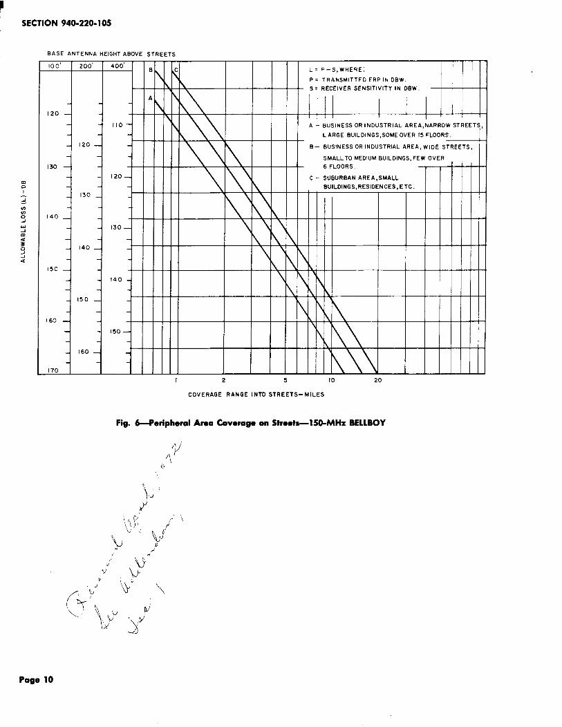
3.o6 Coverage charts (Fig. .5 and 6) provide aconvenient means of estimating in-building
and street coverage where transmitter radiatedpower, antenna height, and type of buildingenvironment involved are known. The effectiveradiated power (ERP) of a transmitting station isexpressed in dB with respect to one watt (dBW).Transmitter output power in dBW is 10 LOG. ofthe power in watts and may be calculated or readdirectly from Fig. 7. Transmitter output powerin dBW, antenna gain, and transmission line losses
are added algebraically to obtain the effectiveradiated power in dBW.
3.o7 The method for estimating coverage consistsof subtracting the signal strength required
(from 2.02) to operate the receiver from the effectiveradiated power of the transmitting station resultingin an allowable path loss which is applied to theproper category of building environment and antennaheight on the charts to determine the coveragerange of the transmitter.
3.08 The primary service area and peripheralstreet coverage area will vary with the
types of buildings in the areas and with antennaheights. Three types of building complexes andthree antenna heights are shown on the charts.Figure 5 should be used to determine the primaryservice area coverage in buildings. Street coveragein the primary service area is assumed in all cases.Figure 6 should be used only to determine thestreet coverage peripheral to the primary servicearea. Approximate ranges for antenna heightsother than those shown on the charts can beobtained by interpolation. The physical height ofthe antenna above street level should be used.The ranges obtained from the charts will be validonly if the antenna is located in the clear and isabove surrounding buildings.
3.o9 These calculations should give an adequateestimate of the service area; however, actual
service area can only be determined by makingfield strength measurements or by test operatingthe receiver in various locations in the proposedservice area.
Page 7

SECTION 940-220-105
I 00I
90.
80 -
\
70
60
50
40
30-
20
10
.10 .20 .30 .40 .50 .60 .70 .80 .90
SIGNALING RELIABILITY
(s INGLE TRANsMl ss 10N -TW TRANSMITTERS)
TPA 558860
Pig. 4-Signaling Reliability vs Building Loss Design Margin at Boundary of Coverage
Page 8

1SS1, SECTION 940-220-105
BAS[ ANTENNA HEIGHT ABOVE STREETS
!00 FT 200 FT 400 FT
E
\ - -
+
s-
120
:1
A-110
I 20
B-130
120
c-130
-1140+ ii+
\ D=
c-
+
“01 1 ,404iiiii ‘Si< 150+ +11111 ‘i-1
160--+ -1 I I t I I I I 7
P-S, WHERE:
TRANSMITTED ERP IN DEW
RECEIVER SENSITIVITY IN OBW
BUS INESS OR INOUSTRI AL AREA
NARROW STR[ETS, LARGE
BUILDINGS, SOME OVER
IS FLOORS.
BUSINESS OR INOUSTR I AL AREA,
WIOE STREETS, LARGE BLOGS,
SOME OVER 1’ FLOORS.
MEDIUM BLOGS AVG 6 FLOORS
NARROW STREETS.
MEOIUM BLOGS AVG 6 FLOORS
!il DE STREETS.
SUBURBAN AREA, SMALL
BUILDINGS, RESIOENTS, ETC. !
-1
1 “o;;-1 +1
i +1
-!
~ “oii,701’601 m
1
0.5 I 2 5 10 20
COVERAGE RANGE INTO BUILOINGS -MILES
TPA 558861
Pig. #rimary Service Area Caverage Within Buildings-150-MHz BELLBOYr) I
/
,)f”,P
P Y \.
Page 9
~
SECTION 940-220-105
BASE ANTENNA HEIGHT ABOVE STREETS
I 2 5 10 20
COVERAGE RANGE INTO STREETS–MILES
Pig. 6-Peripheml Area Coverage on Streets-l SO-MHz BELLBOY
)J
Page 10

1SS1, SECTION 940-220-105
30
0
Fig. 7-Powor in dBW vs Watts
3.10 ~icallkzmy.de: Assume a multitransmittersystem in (1) a business or industrial area
with small to medium height buildings (few oversix floors) on wide streets, (2) a mtimum allowableERP of 500 watts, and (3) an antenna height of100 feet.
(a) Computation of primary service areacoverage in buildings:
150 watts transmitteroutput = +21.8 dBWAntenna gain = + 6.0 dBTypical transmission lineloss =— 0.8 dBEffective radiated power
(ERP) +27.0 dBW (500 W)
Using curve D on Fig. 5 for coverage inbuildings, allowable loss, L (dB), equalstransmitted ERP (dBW) minus receiversensitivity (dBW).
L = +27 dBW — (–126 dBW) frompar. 2.02
= 153 dB
Estimated primary service area coverageon ground floors of buildings is 3.5 milesradius. From Fig. 4, a signaling relia-
(b)
bility of 80 percent or better in 85 per-cent of the buildings at the limit ofcoverage can be expected.
Computation of peripheral coverage instreets bounding the primary in-buildingservice area:
Using allowable loss of 153 dB and curveB on Fig. 6, estimated peripheral streetcoverage is 7.2 miles radius.
3.11 Usually several transmitters are required tocover a metropolitan area. Use of the
maximum allowable ERP is recommended to minimizethe number of transmitters required. The requirementfor minimum separation between cochannel systemsis affected to some extent by multitransmittersystems as described in Part D.
B. Transmitter Site Determination
3.12 With a map prepared to scale showing thedesired primary area to be served as
determined by Marketing and Rate Departmentstudies, determine the approximate transmitterlocations. Using assumed antenna heights, determinethe range from the coverage chart, Fig. 5. A
Page 11

SECTION 940-220-105
more accurate transmitter and coverage determinationshould then be made by selecting actual transmittersites using Telephone Company buildings whereverpossible and substituting actual antenna heightsfor assumed heights. The area in which in-buildingcoverage is desired should be divided into subareaswhich can be typified as building environmentclasses A to E (see categories listed on Fig. 5).The boundary of coverage of each transmitter maybe calculated where the radius of coverage isdetermined by the type area the boundary passesthrough. If in a given direction the environmentchanges from class C to class D before the classC coverage limit is reached, the class D coveragelimit will apply on that radial. Since coveragerange is a direct function of antenna height, andsince shadow losses caused by nearby obstructionsreduce the effective coverage area, every effortshould be made to select antenna sites as highand as in the clear as possible. RF transmissionline losses and installation costs should be givenappropriate consideration in these determinations.
3.13 The purpose in selecting a particular transmittersite is to provide the coverage necessary
for the service. The judgment of site suitabilityinvolves such considerations as antenna height,terrain, cost of site acquisition, construction at thesite, and maintenance accessibility. Dependabilityof the service furnished at a site depends uponthe reliabili@ of the primary power and wire-linefacilities as well as the BELLBOY equipment. Inaddition, local zoning ordinances should be checkedto see that the antenna structure can be erectedwhere desired, and FCC Rules and Regulations,Part 21, should be consulted for regulations regardingthe allowable maximum ERP for the antennaheights being considered.
C Channel Selection
3.14 The two BELLBOY channel assignments,152.84 and 158.10 MHz, are adjacent to the
assignments of existing mobile radio serviceassignments. The 152.84-MHzassignment is adjacentto the 152.81-MHzJR channel (base station transmit,mobile station receive). The 158.1O-MHZassignmentis adjacent to the 158.07-MHz JR channel (basestation receive, mobile station transmit). TheSpecial Industrial Radio Service at 152.87 MHz andthe Power Radio Service at 158.13 MHz are alsoadjacent to the respective BELLBOY channels.These private carrier radio systems usually employthe same frequency for both the base station
transmitter and the base station receiver. Knowingthe geographical location of the adjacent channel .services in the proposed BELLBOY area may behelpful in planning transmitter sites to avoidinterference. Use of the adjacent channels in theproposed area and potential cochannel operationnearby may make one BELLBOY frequency moreattractive than the other in a particular situation.
D. Cochannel Operation
3.15 When a BELLBOY system is to be operatedin an area adjacent to another BELLBOY
system, geographic separation between thetransmitters of cochannel systems must be providedto protect against false signaling of a “home”system receiver by transmission of its code froma “foreign” system assuming that the same codesmust be used in both. Use of discrete codes ormodulation schemes may permit cochannel operation;however, capture in the overlap area may resultin missing some calls. The future potential ofcochannel operation should be considered in engineeringa system.
3.16 The protection desired determines thetransmitter separation to be provided. For
any chosen degree of protection, the requiredseparation will vary with the character of theprotected area and with antenna heights. Aneffective radiated power of 500 watts is generallyassumed. Figure 8 shows the overall probabilityof signaling a receiver out-of-doors as a functionof distance from a 500 watt (ERP) transmitter fora range of antenna heights and environments.Figures 9 and 10 combine the points taken fromFig. 8 to show directly the required distancesbetween the nearest adjoining transmitters of twosystems. Antenna heights for both systems arethe same. Environment of interest is that whereprotection limits of interest fall, not at systemcores.
3.17 For example, assuming a 10-percent chanceof falsely signaling a receiver situated so
far into the fringe of the home area that there isonly a 30-percent chance of receiving a desiredcall, the following estimated separations betweencochannel systems (single transmitter) would apply:
(a) In big city streets, 100-foot antenna height,18.5 miles (Fig. 9)
(b) In big city streets, 450-foot antenna height,36.0 miles (Fig. 9)
Page 12

99
98
95
90
80
70
60
50
40
30
20
10
5
2
I
(c)
(d)
3.18
1SS1, SECTION 940-220-105
5 10 15 20 25 30 35 40 45
OISTANCE FROM TRANSMITTER-MILES
TPA 540472
Fig. B-Probabilityof Signaling a 150-MHz BELLBOY Receiver in Streets
In suburban streets, 100-foot antenna height, may exist. In actual practice the chance of receiving38.0 miles (Fig. 10) a false call is considerably less since a particular
In suburban streets, 450-foot antenna height,receiver would have to b-e present in the fringe
69.0 miles (Fig. 10).area when its code is being transmitted in theadjacent area and when the home transmitter is
Neither the exam~le nor the charts allowoff the air.
for the effects of multiple transmitters in asystem. Multitransmitter layouts can be expected E. Radio Interferenceto enhance the distant field strength. In such casesthe separation between cochannel systems should 3.19 Aa previously mentioned, the characteristicsbe increased by an appropriate amount. Also, and location of nearby radio systems operatingwhen receivers are located on upper floors of in the band and within tlie coverage area of thebuildings, less protection than indicated in Fig. 9 BELLBOY system should be known.
Page 13

SECTION 940-220-105
PERCENT RELIABILITY ‘- ‘- — ‘-
Fig. 9-Reliability of Home Service in Fringe Area-BigCity Streete-150-MHz BELLBOY Service
zimaw~s:aK1-1-Zsq00
5:gu.0z01=a:u(n
12510 20 30 40 5060 70 60 90 95 98 99PERCENT RELIABILITY
Fig. 10—Reliability af Home Service in FringeArea—Suburban/Rural Streets--l5O-MHzBELLBOY Service
3.2o Radio frequency isolators may be requiredto suppress intermodulation products between
transmitters with closely coupled antennas. Eachisolator provides a minimum of 25-dB loss toexternal signals which may result in the generationof intermodulation products in the final amplifier.Isolators may be required where BELLBOYtransmitters are co-sited with Public Land Mobilebase transmitters.
3.21 Spurious RF radiation can be of seriousconcern in the immediate area surrounding
a transmitter site. Radio transmitters may radiatespurious energy over a considerable portion of thespectrum. A filter is provided in all BELLBOYtransmitters to suppress such transmitter noise.Although the spurious RF radiation is of relativelylow level compared to the radiated carrier, it maybe greater than the modulation energy on adjacentchannels in the very near vicinity of the referencetransmitter.
3.22 Potential interference to adjacent channelmobile receivers in the area near BELLBOY
transmitters can be greatly reduced by using gainantennas and locating the antennas as high abovethe ground as possible. Omnidirectional gainantennas direct a major portion of the radiatedenergy in a narrow vertical pattern. Also, by usinggain antennas to obtain maximum effective radiatedpower, fewer transmitters are required for a givenservice area, thus creating fewer potential interferencespots. Co-siting of BELLBOY and mobile basestation transmitters is desirable in those casesinvolving the 152.84-MHz assignment.
3.23 Adjacent channel base station receivers areparticularly susceptible to transmitter noise
and desensitization since they are usually locatedat elevated, low-noise sites. Even with the noisesuppression provided in the BELLBOY transmitter,transmitter noise can be objectionable to adjacentchannel base station receivers within a radius ofapproximately one mile. A strong signal near theoperating frequency of a receiver can causedesensitization of the receiver within a radius ofabout two miles. Every effort should be made toprovide geographic separation of at least one milebetween transmitters and adjacent channel basestation receivers. Crystal bandpass filters orequivalent remedial measures may be required on
Page 14

1SS1, SECTION 940-220-105
adjacent channel base stationwithin a radius of two miles
receivers locatedfrom BELLBOY
transmitters to minimize desensitization effects.Unusual terrain conditions, high noise receiver sites,directional antennas, or lower transmitter powersmight alter these criteria and should be taken intoconsideration.
F. Frequency and Phase Requirements
3.24 The BELLBOY System is designed to utilizeup to 20 radio transmitters operating
simultaneously. In multitransmitter systems it isnecessary to provide (a) precise carrier-frequencycontrol to minimize generation of objectionable beatfrequencies and (b) delay equalization on all audioline facilities to minimize degradation due tocancellation of the signal received from two ormore transmitters.
3.25 To prevent generation of beat tones inreceivers which might interfere with signaling,
the carrier frequency of all transmitters is maintainedwithin about 150 Hz per year. Therefore, thehighest possible beat note between carriers ofadjacent transmitters will not exceed 300 Hz, whichis well below the signaling tone range.
3.26 Phase differences exceeding 45 degrees onthe audio tones feeding multitransmitter
systems will result in impaired service in overlappingcoverage areas. Audi&equency phasing requirementsare met by delay equalizing the line facilitiesbetween the control terminal and each transmitter.Delay equalization information for this system iscovered in Sections 407-200-501, 407-200-508, andAB27.340.1.
3.27 The ability to receive all transmitter carriersfrom a common location is desirable for both
delay and radio frequency measurements. Thisrequires an antenna location capable of receivingsignals from all transmitter sites. A preferablelocation for this central measuring point is thecontrol terminal site since transmitters must beindividually keyed to perform these measurements.
G. Interface Considerations
3.28 The transmitter is arranged to interface withthe J41643B trunk terminating unit to permit
operation with the transmitter trunk originatingunit in the control terminal. Individual trunk unitsare required for each transmitter in the system.
The transmitter trunk terminating unit is installedin the transmitter rack. Repeating coils in theseunits provide appropriate impedance matching andalso derive two dc control paths. Circuits in theinterface units provide relay and transmissionoperations to key and modulate the transmitter.Operating condition indicators, test and make-busyarrangements, and alarms provide individual controlfor each radio transmitter in the system.
3.29 A tone transmission and control trunk isrequired between the transmitter trunk units
of the control terminal and each radio transmitter.Circuit loss of this trunk should not exceed 13 dBat 1000 Hz, and the difference in attenuation forany two frequencies between 500 and 1000 Hzshould not exceed 1 dB. The maximum allowableloop resistance is 10,000 ohms. The control terminaloutput level to the trunk will be – 5.0 dBm foreach tone.
H. Interconnection Arrangements
3.3o The control terminal is arranged only fordial pulse operation. The terminal can be
associated with any switching system which outpulseseither three or four digits. Step-by-Step, No. 5crossbar arranged for line link pulsing, and theNo. 1 ESS are suitable systems. The terminal isserved by a maximum of ten incoming trunks.The range of the incoming trunk register is thestandard range of interoffice dial pulse trunks.Charge or noncharge supervision may be returnedto the connecting trunk.
3.3 I The numbers assigned to BELLBOY receiversare restricted to the series 1000 through
1999, 2100 through 2699, 3000 through 3999, and4100 through 4699. Assigning a central office codeto the control terminal and treating it as an endoffice will result in an inefficient use of telephonenumbers. Therefore, it is recommended that asuitable method of office code sharing be selected.Shared office code arrangements must overcomethe restricted thousands number assignment of thecontrol terminal. The 1 through 4 thousand numberblocks may be in use in the existing central officewhile other number blocks are available. InStep-by-Step systems, through establishment ofseparate trunk groups for each thousands numberblock, any available thousands number block maybe used with only three digits pulsed to the controlterminal. The control terminal will simulate theappropriate thousands digit. This method has the
Page 15

SECTION 940-220-105
serious defect of decreasing trunk efficiency. Whenall ten trunks are used as a single trunk group,the traffic load for a full complement of 3200receivers can be adequately handled and provide agrade of service of P.01. However, when the tentrunks are split into groups of 3, 2, 8, 2, only 860receivers can be served and maintain the establishedP.01 grade of service. A better approach is availablein the No. 5 crossbar and No. 1 ESS systems.Code conversion arrangement may be used to deletethe first four digits of the seven digit receivernumber and insert the desired thousands digit.The last four digits may then be outpulsed over acommon trunk group to the control terminal.
3.32 Connections to intercept unassigned numbersare established through the control terminal
to central office intercept facilities. If the associatedcentral office is not arranged for vacant numberintercepting, other arrangements such as theprovisionof a specialBELLBOYintercept announcementset must be made.
3.33 Traffic usage observations should preferablybe made in the originating office by using
a traffic usage recorder (TUR) on the trunks assignedto the control terminal. If no TUR is available inthe originating office, observations may be madein the office containing the control terminal byusing leads brought out from the incoming trunkregister circuit
4. LICENSEAPPLICATION PROCEDURES
4.o1 Section 400-521-100 discusses the generalconsiderations involved in obtaining FCC
authorizations for the establishment of commoncarrier radio stations. The section contains referencesfor the preparation of all applicable forms. Ofparticular interest is the need for a closely coordinatedschedule of FCC processing and constructionintervals. Failure to prepare a realistic overallschedule can result in delays in FCC authorizationsand/or missing a service date.
5. EQUIPMENT ENGINEERING CONSIDERATIONS
5.01 Equipment engineering information for controlterminal equipment is furnished in Section
AA295.006. The control terminal may be orderedand equipped in any combination of incoming trunkregisters, storage units, and number check unitsrequired to satisfy traffic loading in a particularsystem. The terminal is made up of four, five,
or six loop shop-wired and tested bays. Thesebays should be located adjacent to one another in .a single lineup. It is recommended that an initialsystem be equipped for no less than 600 customersand include at least four incoming trunk registers,three number check circuits, and ten stores.Equipment that is vital to the operation of theterminal is duplicated for system reliability.
5.02 The provision of 36A tone oscillators andcrystals for the terminal will depend upon
the number translation plan authorized for theterminal and the number groups to be served.Regular and standby oscillators are required foreach discrete coding element tone used in thereceivers of the system. Dummy load networksare required in all unused tone oscillator positionsin the terminal. It may be noted from the numbertranslation plan that it is desirable to assign numberswholly within certain number series. Tone frequenciescorresponding to the third and fourth digits arethe same throughout the 1000 through 1999 and2100 through 2699 series of numbers. Similarly,they are the same throughout the 3000 through3999 and 4100 through 4699 series. This easestone generator requirements, simplifies the provisionof coding elements for receivers, and enables orderlyexpansion of the system.
5.o3 Intercept trunk units are provided in thecontrol terminal for connection to central
office intercept facilities. The intercept trunk unitsare not required when direct association with aspecial BELLBOY intercept announcement set isemployed.
5.04 Delay equalizers required in transmittertrunks of multitransmitter systems are
installed in the control terminal. Attenuationequalizers may be installed in the terminal if spaceis available or on central office miscellaneousframes.
5.05 The KS-20429 Radio Transmitter may beordered by various list numbers to meet
the requirements of a particular site. A J41643BTransmitter Trunk Terminating Unit is requiredfor each transmitter. Equipment engineering forthese units is contained in Sections AA290.020 andAA290.025.
5.o6 Antennas and transmission lines of severaltypes and suppliers are available to meet
gain and radiation requirements at each transmitter
Page 16

~-”site. Supporting structures and all material requiredfor antenna installation are ordered as specifiedlocally.
5.07 The KS-20432 Radio Receiver is furnishedfor operation on one of the two BELLBOY
frequencies as specified. Customers are normallyfurnished a receiver equipped with three codingelements and one battery plus a charger. Extrabatteries and charging adapters are optional. Thereceiver may be operated while in the charger;however, the charging rate is about half the normalrate. The receiver, battery, or charger will notbe adversely affected should the receiver remainon charge for an indefinite period. See SectionU290.025 for equipment engineering information.
5.o8 Coding element requirements for a givencustomer number block may be determined
from the number translation plan authorized forthe system. It will be necessary in each case tocompute the total number of coding elementsrequired for the numbers to be assigned.
5.09 Customer service receiver maintenance isgenerally performed on a go/no-go basis by
install~g new ba-tiries and/or co-tig e~ment.s. ifthese measures fail, a new receiver with the samecoding elements is provided to the customer.Therefore, extra receivers, coding elements, andbatteries are required. A complement of 5 percentspares is suggested for receivers, batteries, andeach of the discrete coding elements in use in thesystem.
6. TESTEQUIPMENT
6.01 A general survey of test equipment on handand that required for a BELLBOY system
should be made to avoid unnecessary expense andto insure that specific test equipment is availableto perform necessary maintenance. Equipmentrequired for maintenance is described in sectionscovering tests to be performed. Any item withequivalent ratings can be substituted for thosespecitled. Any substitution should utilize equipmentof equal accuracy and stability.
7. SYSTEM ACCEPTANCE TESTS
7.o1 Each BELLBOY system must be lined upand thoroughly tested before being placed
in service. This includes the following
(a)
(b)
(c)
(d)
and
(e)
(f)
(g)
(h)
(i)
1SS1, SECTION 940-220-105
Transmission and delay equalization of wirelines.
Tuning, power, frequency, and modulationchecks of all transmitters.
Frequency and level checks of 36A oscillators.
Operation and level checks of announcementsets including acknowledgement, trouble,station identification.
Operation of intercept trunks.
Alarm and control of all transmitters.
Complete operational check of the controlterminal.
Verify coverage with test BELLBOY receiverand prepare a coverage map.
Advise FCC and all Telephone Companydepartments concerned before turning up
system for service.
8. REFERENCES
8.01 References mentioned inand others of particular
below
Befl System ??ractices
the foregoing textinterest are listed
SECTION TITLE
AA290.020 Personal Signaling System—Transmitter Trunk TerminatingUnit
AA290.025 150 MHz Radio—BELLBOYPersonal Signaling System
AA295.006 J1 Control Terminal-BELLBOYPersonal Signaling SystemI
AB27.340.1 MobileTelephoneSystems-DelayEqualization of Channels Providedfor Multistation Radio Systems
400-521-100 Radio Administration—FCCRegulatory Information
Page 17

SECTION 940-220-105
ISECTION
407-200 Series
407-201 Series
407-204 Series
407-207 Series
407-210-100
940-230 & 240Series
TITLE
Personal Radio Services—150MHzBELLBOY4erall System
Personal Radio Services-150MHz BELLBOY-Radio Trans-mitter
Personal Radio Services—150MHz BELLBOY-Radio Receiver
Personal Radio Services-150MHz BELLBOY—J1 ControlTerminal
Personal Radio Services—150MHz BELLBOY—AuxiliaryEquipment
Radio Engineering—MobileRadio
lhgineering Lettem and Memoranda
E. L. 259—Interconnection Arrangementsfor One-Way Signaling Systems
E. L. 314—BELLBOY Personal SignalingServicesPlanning ad Engineering150 MHz BELLBOY Systems(Including price and ordering
J%@ineering Lettem and Memoranda
E. M. 1620--Test Equipment Required for “Maintaining 150MHz BELLBOYPersonal Signaling Systems
E. M. 1651—Nationwide Tone-SubscriberNumber Translation Plan for150 MHz BELLBOY Systems
Marketing htter, May 9, 1969-BELLBOYPersonal Signaling Service
Rate/Marketing Letter, June 24, 1970(GL70-0&185>Illustrative 15@MHzBELLBOYPricing Approach
Engineering Cost Letter, June 30, 1970(GL70-MW28)-Illustrative 15@MHzBELLBOYCost Study
Other References
(1) Mitchell, Doren, and K. G. Van Wynen. A150 Mc Personal Radio Signaling System,
Bell System Technical Journal, September1961, pp. 1239-1257.
(2) Rice, L. P. Radio Transmission into Buildingsat 35 and 150 Mc, Bell System Monograph
information) 32?34.
Page 1818 Poges