radiation stability of plastics and elastomers (supplement
TRANSCRIPT

^:*
->• JJ
fia?& ^ -&^CENTRA]
3 14145b 03bDk.07 i
RADIATION STABILITY OF PLASTICS
AND ELASTOMERS
(Supplement to ORNL-928)
C. D. Bopp0. Si smart
^iiL
ORNL 1373
Engineering
*?•*
Oak Ridge National LaboratoryOPERATED BY
Carbide and Carbon Chemicals CompanyA DIVISION OF UNION CARBI.DE AND CARBON CORPORATION
POST OFFICE BOX P
OAK RIDGE, TENNESSEE

Contract No. W.7405-«na-26
SOLID STATE DIVISION
RADIATION STABILITY OF PLASTICS AND ELASTOMERS
(Supplement to ORNL-928)
C. D. Bopp0. Sisman
Experimental Measurements by
W. K. Kirkland
R. L. Towns
July 23, 1953
DATE ISSUED
- 1 <#5*
OAK RIDGE NATIONAL LABORATORYOperated By
CARBIDE AND CARBON CHEMICALS COMPANYA Division of Union Carbide and Carbon Corporation
Post Office Box POak Ridge, Tennessee
ORNL-1373
Copy No. '
MARTIN MARIETTA ENERGY SYSTEMS LIBRARIES
3 445b D3b0b07 1


INTERNAL DISTRIBUTION
1. C. E. Center
2. Biology Library3. Health Physics Library
"^^6. Central Research Library6. Reactor Experimental
Engineering Library7-11. Laboratory Records Department
12. Laboratory Records, ORNL R.C.13. C. E. Larson
14. L. B. Emlet (K-25)15. J. P. Murray (Y-12)16. A. M. Weinberg17. E. H. Taylor18. E. D. Shipley19. D. S. Billington20. F. C. VonderLage21. R. C. Briant
22. C. P. Keim
23. J. A. Lane
24. J. H. Frye, Jr.25. R. S. Livingston26. J. A. Swartout
27. S. C. Lind
28. F. L. Culler
29. A. H. Snell
30. A. Hollaender
31. M. T. Kelley32. G. H. Clewett
33. K. Z. Morgan34. T. A. Lincoln
35. A. S. Householder
36. C. S. Harrill
ORNL 1373
Engineering
37. C. E. Winters
38. D. W. Cardwell
39. E. M. King40. A. J. Miller
41. J. T. Howe
42. D. D. Cowen
43. P. M. Reyling44. G. C. Williams
45. J. H. Crawford
46. T. H. Blewitt
47. J. C.Wilson
48. J. B. Trice
49. W. W. Parkinson
50. C. D. Bopp51. G. E. Moore
52. A. R. 01 sen
53. G. W. Keilholtz
54. S. E. Dismuke
55. R. A. Weeks
56. C. D. Cagle57. J. A. Cox
58. C. D. Watson
59. R. B. Briggs60. R. N. Lyon61. J. L. English62. H. F. Poppendiek63. E. G. Bohlmann
64. L. C. Oakes
65. A. R. Jones
66. C. J. Hochanadel
67-166. 0. Sisman
167. M. J. Skinner
EXTERNAL DISTRIBUTION
168. R. F. Bacher, California Institute of Technology169-412. Given distribution as shown in TID-4500 under Engineering Category
DISTRIBUTION PAGE TO BE REMOVED IF REPORT IS GIVEN PUBLIC DISTRIBUTION


CONTENTS
ACKNOWLEDGMENT vi
ABSTRACT ]
INTRODUCTION ]CHAPTER 1. Radiation Stability of Commercial Elastomers 2CHAPTER 2. Radiation Stability of Specially Compounded Elastomers 21CHAPTER 3. Radiation Stability of Commercial Plastics 25CHAPTER 4. Damage by Radiation Other Than Reactor Radiation 52CHAPTER 5. Effect ofOxygen and the Time of Aging After Irradiation 59CHAPTER 6. Radiation-induced Change in the Specific Volume 61CHAPTER 7. Radiation-induced Gassing 63DISCUSSION OF RESULTS 68
BIBLIOGRAPHY 71APPENDIX. Test Procedures for Elastomers 72INDEX FOR THE PROPERTIES OF IRRADIATED ELASTOMERS AND PLASTICS 81

ACKNOWLEDGMENT
Specimens used for testing were supplied by many people, and their cooperation isgreatly appreciated. The B. F. Goodrich Research Center compounded most of therubber specimens, and the help of W. L. Davidson of the Goodrich Company in selectingthe materials to be studied and the tests to be run is gratefully acknowledged.
***sp»4m*$**- ##ap«s*#s*tfi-^igfifflfcMwii',.,.
RADIATION STABILITY OF PLASTICS AND ELASTOMERS
C. D. Bopp 0. Sisman
ABSTRACT
Radiation-induced changes in the physical properties of several plastics that were not includedin ORNL-928 and the radiation-induced changes in the commercial elastomers are reported. In
addition, a number of fabrics and some specially prepared materials are examined.For the most part, reactor radiation was used, but other types of radiation are compared with
reactor radiation in producing changes in the properties of the materials studied. The effect ofthe presence of oxygen during irradiation and the effect of time of aging subsequent to irradiation
are also studied. The rate of gas evolution and the rate of change in volume are given for many
of the materials studied, and a correlation is drawn with the chemical structure. Also, changes
in the mechanical properties of the polymers are correlated with their chemical structure.
INTRODUCTION
This report is a supplement to a previous study(I)* of the radiation stability of a number of commercial plastics. The radiation stability of commercial elastomers is described in Chapter 1; thestability of a number of additional plastics isdescribed in Chapter 3.
All soft, flexible plastics and elastomers whichare not extensively degraded by radiation arehardened by cross-linking. Attempts made to increase resistance to hardening are described inChapter 2. Mixtures of natural rubber and butylrubber were tried, and the effect of increasing thefiller material and the antioxidant in elastomer
formulations was determined, but none of thesemeasures were successful.
Most of the radiation exposures were made in themaximum flux region of the ORNL Graphite Reactor.Exposures made with other types of radiation aredescribed in Chapter 4. To increase the intensityof ionizing radiation, some irradiations were conducted in which the materials were wrapped incadmium during the exposure. Even then, some ofthe hard plastics showed but small change afteran exposure of six months. Irradiations are plannedat higher intensities in high-flux facilities whichhave recently become available.
Comparison of the damage from fast-neutron andgamma radiation was made from the increase indamage for cadmium-wrapped specimens. [Sincedamage by thermal neutrons is small for materials
"See bibliography.
with low absorption cross sections, the effect ofthe cadmium is to produce additional gamma-radiation damage by converting thermal-neutron togamma radiation bythe (n,y)reaction.] Comparativeirradiations were also made with neutron-free gammaradiation from Au198 and Co60 sources. A studyof the effect of intensity was made with the Cosource by varying the distance from the source andincreasing the exposure for the irradiations madefurther from the source so that approximatelyequal energy absorption for all irradiations wouldbe produced. The energy absorption required toproduce similar changes in most of the physicalproperties of the materials studied was the samewithin a factor of about 2 for the various sources
of ionizing radiation employed.Listed in Chapters 6 and 7 are the change in
volume and the evolution of gas which accompanythe radiation-induced cross-linking of many of thepolymers. Certain other polymers show no uniformdecrease in volume. It is thought that the decreasewhich would otherwise be produced by cross-linking is masked by chain cleavage. Gassingoccurs even for polymers which are degraded extensively by chain cleavage. More than likely,most of the gassing results from cross-linking, sincethe hydrogen produced by cross-linking can diffusemore readily through the polymer than can thehydrocarbons produced from chain cleavage.
Listed in "Discussion of Results" is a corre
lation of the radiation stability with the chemicalstructure of the materials tested. This correlation

permits prediction of the behavior of materialswhich have not been tested.
The present study has been confined to room-temperature conditions. While certain hard materialshave good stability and show little change, allsoft materials (which are not degraded) are hardened. For this reason, it is not expected that changesin temperature will greatly affect the stability ofhard, resistant materials until the point is reached
at which the material becomes soft and elastic.It is therefore planned to study the stability ofthese materials at their softening points.
In certain instances, good stability is shown bymixtures of certain polymers and mineral fillers,although the polymers alone show poor stability.This applies only for hard materials and not tosoft, flexible materials. It is planned to studythis effect more fully.
Chapter 1
RADIATION STABILITY OF COMMERCIAL ELASTOMERS
GROUP 1 FORMULATIONS
Commercial elastomer formulations, for the mostpart, are based on eight polymers, although alarge number of formulations exist that suit variousapplications. Owing to poor mechanical propertiesfor uncompounded polymers, vulcanized formulations were chosen for testing. Gasket formulationswere chosen over electrical insulation formulationssince mechanical properties were to be studiedmore intensively than electrical properties. Therecipes of the first group of elastomers tested(Group 1) were chosen so that each material wouldhave durometer hardness in the range from 60 to70. The recipes are listed in Table 1.1.
During irradiation, the materials were sealed inair (see Chapter 5) in aluminum cans. Exposureswere conducted in hole 19 of the ORNL GraphiteReactor. This irradiation facility is more fullydescribed in a report (2) in which the fast-neutronflux (above 1 Mev) is estimated as 4% of the thermalflux, the epithermal flux above the cadmium cut-offis estimated as 60% of the thermal flux, and thegamma flux (if the energy of the gammas is takenas 1 Mev) is estimated as 50% of thermal flux.The radiation exposure is listed as nvt, the productof the thermal-neutron flux in neutrons/cm -sec andthe exposure time in seconds.
Descriptions of the testing procedures are givenin the Appendix. Most of the tests are modifications of ASTM standard procedures. The testinglaboratory was kept at 50 + 2% relative humidityand 77 ±2°F. Test results are given in Figs. 1.1through 1.9. The chemical structural formulas aregiven in Table 1.2. Stress-strain curves are givenfor several radiation exposures, and other physicaland mechanical properties are plotted as a functionof exposure.
Natural rubber, Neoprene W, GR-S, Hycar OR,Hycar PA, and Silastic 7-170 all harden withirradiation. Butyl rubber and Thiokol soften withirradiation. Both butyl rubber and Thiokol eventually become fluid; however, about 20 times theexposure is required to produce softening in Thiokolas is required for softening butyl rubber to thesame extent. A comparison of the change in durometer hardness for the polymers is shown in Fig. 1.10.
Although the tensile strength of Hycar OR andSilastic is initially increased, long exposurecauses the strength to be decreased. The tensilestrength of the other elastomers is decreased, withno initial increase. The materials which are
hardened regain tensile strength after long exposure, but only after severe embrittlement hasreduced the elongation to less than 1% of theinitial value. Since the materials are hard and
brittle at this time, they have none of their originalelastomeric characteristics.
Irradiation increases the specific gravity of theelastomers which are hardened and decreases thespecific gravity of the elastomers which aresoftened.
A marked loss in weight occurs only for Thiokoland Hycar PA.
The volume resistivity deteriorates only forNeoprene Wand Hycar PA. It is believed that thechange in electrical properties of these two plasticsis associated with their hygroscopicity, whichdevelops after long exposure and is due to HCIformation. Neoprene W contains chlorine, as isshown by its structural formula in Table 1.2;Hycar PA contains a very small amount of chlorine-containing material, although this is not shown inits structural formula.
^^?t&^fa&>$4*- i.t
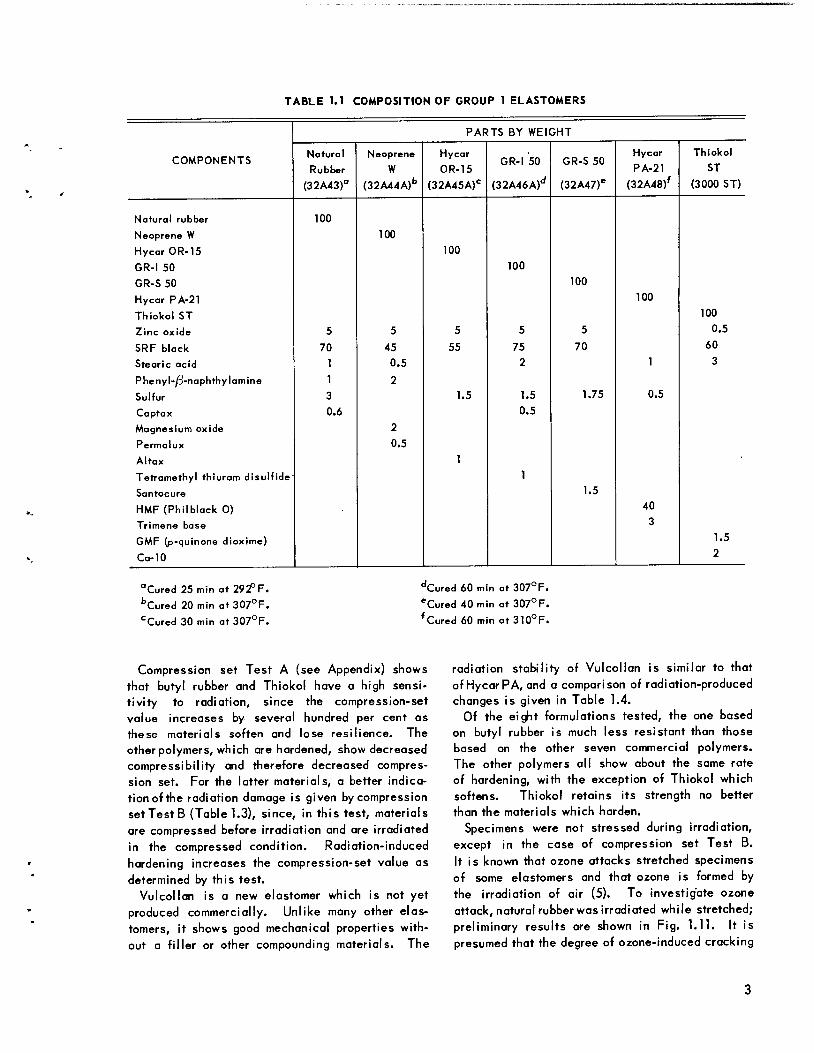
TABLE 1.1 COMPOSITION OF GROUP 1 ELASTOMERS
PARTS BY WEIGHT
COMPONENTSNatural
Rubber
Neoprene
W
Hycar
OR-15GR-I 50 GR-S 50
Hycar
PA-21
Thiokol
ST
(32A43)° (32A44A)b (32A45A)C (32A46A)d (32A47)e (32A48)f (3000 ST)
Natural rubber 100
Neoprene W 100
Hycar OR-15 100
GR-I 50 100
GR-S 50 100
Hycar PA-21 100
Thiokol ST 100
Zinc oxide 5 5 5 5 5 0.5
SRF black 70 45 55 75 70 60
Stearic acid 1 0.5 2 1 3
Phenyl-/3-naphthylamine 1 2
Sulfur 3 1.5 1.5 1.75 0.5
Captax 0.6 0.5
Magnesium oxide 2
Permalux 0.5
Altax 1
Tetramethyl thiuram disulfide 1
Santocure 1.5
HMF(Philblack 0) 40
Trimene base 3
GMF (p-quinone dioxime) 1.5
Ca-10 2
"Cured 25 min at 292° F.
bCured 20 min at 307°F.cCured 30 min at 307°F.
dCured 60 min at 307°F.'Cured 40 min at 307°F.
fCured 60 min at310°F.
Compression set Test A (see Appendix) showsthat butyl rubber and Thiokol have a high sensitivity to radiation, since the compression-setvalue increases by several hundred per cent asthese materials soften and lose resilience. The
other polymers, which are hardened, show decreasedcompressibility and therefore decreased compression set. For the latter materials, a better indication of the radiation damage is given by compressionset Test B (Table 1.3), since, in this test, materialsare compressed before irradiation and are irradiatedin the compressed condition. Radiation-inducedhardening increases the compression-set value asdetermined by this test.
Vulcollan is a new elastomer which is not yetproduced commercially. Unlike many other elastomers, it shows good mechanical properties without a filler or other compounding materials. The
radiation stability of Vulcollan is similar to thatof HycarPA, and a comparison of radiation-producedchanges is given in Table 1.4.
Of the eight formulations tested, the one basedon butyl rubber is much less resistant than thosebased on the other seven commercial polymers.The other polymers all show about the same rateof hardening, with the exception of Thiokol whichsoftens. Thiokol retains its strength no betterthan the materials which harden.
Specimens were not stressed during irradiation,except in the case of compression set Test B.It is known that ozone attacks stretched specimensof some elastomers and that ozone is formed bythe irradiation of air (5). To investigate ozoneattack, natural rubberwas irradiated while stretched;preliminary results are shown in Fig. 1.11. It ispresumed that the degree of ozone-induced cracking

Natural rubber
GR-S
TABLE 1.2. STRUCTURAL FORMULAS OF ELASTOMERS
H CH, H HI I J I I
-C-C =C-C-I I
H H
Butyl rubber GR-I -
H CH, H HI I J I I
-C-C = C-C-l-
Neoprene
Hycar OR
Hycar PA
Silastic
Thiokol
Vulcollan
H CI H HI I I I
•C-C=C-C-I I
H H
Hi
H
C-i
-C-
H CO1
0
C2H5
CHI 3
Si -0-
CH,
H H S SI I I I
-C-C-S-S-
H H
-0-
0 0II II
-C-R-C-O-
H H 0 O H HI I II II I I
-C-C-O-C-N-R'-N-C-O-C-C-II I I II
H H H H H H
(x/y = 6)
(x/y = 50)
(x/y = 2)
(alsoC98H)28044N4)

is affected by the amount of elongation, the circulation of air, the radiation intensity, and the exposure period. (The importance of the circulationof air is shown by the fact that the side of thespecimen which was partially shielded by thestretching jig showed no attack.) It is planned to
investigate more fully the effect of these conditions of exposure. Owing to the merging of cracks,the depth of cracks rather than the width or numberwill be used as a measure of the severity ofattack (6).
TABLE 1.3. RECOVERY OF ELASTOMERS COMPRESSED 25% DURING IRRADIATION
Compression Set Test B
RECOVERY (%)
In Jig 190 hr In Jig 840 hr
ELASTOMER Irradiated, Irradiated,
Unirradiated 0.03 X 10¹⁸ nvt(7.5 hr in reactor)
Unirradiated 0.16 X 10¹⁸ nvt(40 hr in reactor)
Natural rubber
(32A43) 93 52 90 25
GR-S 50
(32A47) 90 53 88 22
Butyl rubber, GR-I
(32A46) 91 23 88 Tarry fluid
Neoprene W
(32A44) 62 20 42 12
Hycar OR-15
(32A45) 92 62 90 24
Hycar PA-21
(32A48) 92 58 91 14
Silastic 7-170 97 27 95 0
Thiokol ST
(3000 ST) 90 2 82 0
TABLE 1.4. RADIATION-PRODUCED CHANGES IN VULCOLLAN COMPARED WITH THOSE IN HYCAR PA-21
IRRADIATION
EXPOSURE
(1018 nvt)
TENSILE
STRENGTH
(psi)
ELONGATIONSHORE
DUROMETER
HARDNESS
SHORE
ELASTICITY
SPECIFIC
GRAVITY,
25/4°C
CHANGE
IN WEIGHT
(%)
VOLUME
RESISTIVITY
(ohm-cm)
DIELECTRIC
STRENGTH
(volts/mil)
Hycar 0 2000 330 62 70 1.269 10'° 115
PA-210.12 1400 115 70 50 1.270 -0.1 115
1.6 400 20 88 25 1.276 -1.7 115
5.4 1500 2 99 1.290 -7.0 106 115
Vulcollan 0 5400 600 74 100 1.237 3 x 10⁸ >210
0.12 1900 250 72 80 1.242 0.05 3 x 10⁸ >210
1.6 600 50 74 30 1.245 -0.19 3 x 10⁸ >210
5.4 240 10 90 25 1.256 -5.8 3 x 10⁸ 200

400
</> 200
2? /0/
0/
1y^
C7 ^c^
0.1 0.2 0.3 0.4
STRAIN IN COMPRESSION (in./in.)
(<7)
* BREAK NG POINT
5> -\O toj ^
/
•V of / >
2.0 3.0 4.0
STRAIN IN TENSION (in./in.)
(£)
0.01 0.1
FLUX (1018nvt)(c)
200
z> 150
I +0.5
UNCLASSIFIEDDWG. 21537
1 1
SYMBOL PROPERTY *INITIAL VALUE
O COMPRESSION SET TEST A 13%
A STRAIN AT 400 psi 30%
O^ft\i
\
0.1
FLUX (1018 nvt)id)
<s>
0.001 0.1
FLUX (1018 nvt)
(e)
1.0 10
A0/
oyT
0.001
Fig. 1.1. Physical and Mechanical Properties of Irradiated Natural Rubber (32A43).
#SiiS»«i*B«si«as9!^^

0.1 0.2 0.3 0.4
STRAIN IN COMPRESSION (in./in.)
[0)
0.5
* B REAKING PO NT
2
1-H i1 c/
/S1
/ \
/ °'
* f
s>
1.0 2.0 3.0 4.0
STRAIN IN TENSION (in./in.)
(i>)
SYMBOL PROPERTY * INITIAL VALUE
O TENSILE STRENGTH 1700 psi
- A — ELONGATION 270%A SET AT BREAK 5%
UNCLASSIFIED
DWG. 21538
1 1
PROPERTY * INITIAL VALUE
COMPRESSION SET, TEST A 4.7%STRAIN AT 400 psi 28%
0.001 0.01 0.1
FLUX (1018 nvt)
id)
I. . J . TAP]o n—a o o— o^-
-0.5 L
5 1.24
1.20
0.1
FLUX (10'8 nvt)
(e)
d —o »
0.01 0.1 1.0
FLUX (10'8 nvt)
if)
Fig. 1.2. Physical and Mechanical Properties of Irradiated GR-S 50 (32A47).

0 0.1 0.2 0.3 0.4
STRAIN IN COMPRESSION (in./in.)
(C)
- 1000
150
1.0 2.0 3.0 4.0
STRAIN IN TENSION (in./in.)
(4)
SYMBOL
O
PROPERTY
TENSILE STRENGTH
ELONGATION
SET AT BREAK
•X- INITIAL VALUE
1100 psi
525 %
35%
0.01 0.1 1.0
FLUX do'8 nvt)
(C)
0.5
0
-0.5
0.001
1.20
UNCLASSIFIED
DWG. 21539
! 1 1SYMBOL PROPERTY * INITIAL VALUE
O COMPRESSION SET, TEST A 7.2%A STRAIN AT 400 psi 31%,
-o o——&
0.1
FLUX (1018 nvt)
(e)
3=FLUX (10 nvt)
Fig. 1.3. Physical and Mechanical Properties of Irradiated Butyl Rubber, GR-I 50 (32A46).

it A
0.1 0.2 0.3 0.4
STRAIN IN COMPRESSION (in./in.)
3>
o
•V-rv/ <5
/ /*BREAKI MG POINT
<n 1000 —
50
1.0 2.0 3.0 4.0
STRAIN IN TENSION (in./in.)
(i>)
SYMBOL PROPERTY
O TENSILE STRENGTH
A ELONGATION
• SET AT BREAK
'INITIAL VALUE
2900 psi
450%
6%
0.001 0.01 0.1 1.0
FLUX (1018 nvt)(c)
50
UNCLASSIFIEDDWG 21540
1 1
SYMBOL PROPERTY "INITIAL VALUEO COMPRESSION SET, TESTA 9.0%
A STRAIN AT 400 psi 31%
a\\v A
s—ids—0.001 0.1
FLUX (I0,8nvt)(cO
1.0 10
i + 0.5
LU
* oZ
LCJ5 -0.5
0
0.001 0.1 1.0
FLUX [1018 nvt)u
~ 1.48u
V« 1.46C\J
>-
t 1.44<
u 1.40
r\ -*Soo 0 0
«5 0.001
0.001
Fig. 1.4. Physical and Mechanical Properties of Irradiated Neoprene W(32A44).

•5 2000
1000
200
10
I* vA/
^ i
0.1 0.2 0.3 0.4
STRAIN IN COMPRESSION (in./in.)
(0)
0.5
S> /o/
- Pi*& Av/to/o7
7 #?7#/-w ^-*y
<y
*BREAKING POINT
/ V X
1.0 2.0 3.0 4.0
STRAIN IN TENSION (in./in.)
it)
SYMBOL PROPERTY *INITIAL VALUE J
O TENSILE STRENGTH 1900psi JA ELONGATION 250% 1_• SET AT BREAK 3% 1!?
O _J3-
2 1 n-o 1 ^
o 1 o
" <O
•
— 1 o
1 / ^
>v •
» A A
0.1
FLUX (I018nvt)
{C)
150
50
-0.5
0.001
1.32
t)
1.40m
OJ
•>-1.28
i-
<rr 1.26iD
u
u. 1.^4< >hinU) \.zz
UNCLASSIFIEDDWG. 21541
SYMBOL
A
O
PROPERTY INITIAL VALUE
COMPRESSION SET, TEST A 9.5%
STRAIN AT 400psi 25%
\p ^v^
\ \o
i A
0.1
FLUX (1018 nvt)
{d)
1.0
In ^A
FLUX (10'° nvt)
(<?)
°f
FLUX (10°nvt)
(/)
1.0
100 —pD—O 0 0
50
-—_A^^•SHORE ELASTICITY
-SHORE DUROMET LK HAKUNhSS
0
0.1
FLUX (1018 nvt)
(<7)
Fig. 1.5. Physical and Mechanical Properties of Irradiated Hycar OR-15 (32A45).

3000
200
150
0.1 0.2 0.3 0.4
STRAIN IN COMPRESSION (in/in)
(a)
1.0 2.0 3.0 4.0
STRAIN IN TENSION (in./in.)
(A)
SYMBOL PROPERTY ^INITIAL VALUE
0 TENSILE STRENGTH 2000 psiA ELONGATION 230%
• SET AT BREAK 10%
s
\\ °\
0.001 0.1 1.0
FLUX (10,s nvt)
UNCLASSIFIED
DWG 21542
0.001
-7! 0
FLUX H0'° nvt)
(d)
•o o
0.01 0.1 1.0
FLUX (101envt)(e)
10
1.30
1.29
1.28
1.27 } u
0.001 0.01 0.1 1.0
FLUX (1018nvt)(f)
100
SHORE DUROMETER HARDNESS-
0.001 0.01 0.1 1.0
FLUX (10,8nvt)
(?)
Fig. 1.6. Physical and Mechanical Properties of Irradiated Hycar PA-21 (32A48).
11

400
150
2 100
12
0.1 0.2 0.3 0.4
STRAIN IN COMPRESSION (in./in.)
(<7)
* BREAKING POINT
UNIRRADIATED
nvt = 0.04 x10¹⁸
nvt= 0.08 xtO1
nvt= 0.2 x10'
.18
0 2.0 3.0 4.0
STRAIN IN TENSION (in./in)
U>)
PROPERTY
TENSILE STRENGTH
ELONGATION
1
* INITIAL VALUE
520 psi
95%
o o
-2
0.00
UNCLASSIFIED
DWG. 21543
SYMBOL PROPERTY * INITIAL VALUE
O COMPRESSION SET, TEST A 1.4%A STRAIN AT 400 psi 3.4%
—o
0.01 0.1
FLUX (I0,E(e)
^ n
Fig. 1.7. Physical and Mechanical Properties of Irradiated Silastic 7-170.

w 200
500
<&A/<A%yA>
0.1 0.2 0.3 0.4
STRAIN IN COMPRESSION (in./in.)
(O)
0.5
* BREAKI NG POINT
f UN
< nvt=0.04 X
X1018
IRRADIATED
io'8
X nvt=
1.0 2.0 3.0 4.0
STRAIN IN TENSION (in./in.)
ib)
SYMBOL PROPERTY
O TENSILE STRENGTH
A ELONGATION
• SET AT BREAK
FLUX (10 nvt)
(C)
INITIAL VALUE
800 psi
162%
3%
UNCLASSIFIEDDWG. 21544
SYMBOL PROPERTY "INITIAL VALUEO COMPRESSION SET, TEST A 9%
1000
A STRAIN AT 400 psi 26%
I ICRUMBLED AT LESS THAN^-^1 *
400psi STRESS—-^^ /
__^0.1
FLUX (1018nvt)
10
0
0.5
1 O
(d)
—o-—o o—^^
0.001 0.1
FLUX (1018 nvt)(fi)
10
1.5
1.4
1.3
1.2
1.0
0.001
6 1—o o—o. jx^
100
0
0.001
0.1
FLUX (IO18 nvt)
(f)
_o o—o-
"SHORE DUROMETER HARDNESS
"SHORE ELASTICITY^
FLUX (to nvt)
(?)
Fig. 1.8. Physical and Mechanical Properties of Irradiated Thiokol ST (3000ST).
13

UNCLASSIFIED
DWG. 187048000
6000
V) 4000enUJ
or\-
2000
^BREAKING POINT
>
\1>
^
t^^
1.0 2.0 3.0 4.0
STRAIN IN TENSION (in./in.)
5.0 6.0
Fig. 1.9. Stress-Strain Curves for Irradiated Vulcollan.
Since frictional heating is an important consideration in the design of synthetic rubber tires, it isplanned to investigate the effect of radiation ondynamic losses. A vibrating-reed type of measurement (7) will be employed.
GROUP 2 FORMULATIONS
The contention that the polymer portion of thematerial determines, for the most part, the radiationstability of elastomer formulations is supported bystudies made on a second group of formulations(Tables 1.5 and 1.6). These materials were provided by the Materials Laboratory of the WrightAir Development Center. Not so many radiationexposures were made in this instance, since it wasexpected that results would be very similar tothose obtained for Group 1. The results obtained
14
on the Group 2 formulations are shown in Tables1.7 and 1.8.
Each formulation of Group 2 shows similar stability to the formulation of Group 1 that includesthe same polymer (Hycar OS is similar to GR-S).Three additional polymers are included in Group 2:Neoprene GN, Hypalon, and FBA. The elastomersbased on these three polymers are hardened likemost other elastomers.
The natural rubber formulations which include
various plasticizers all show similar stability andare hardened at about the same rate as the natural
rubber formulation without a plasticizer.The experimental procedure used for Group 2 was
similar to that employed for Group 1, except thatGroup 1 elastomers were irradiated in cans whichcontained air, while the air was replaced by heliumfor Group 2 irradiations. The effect of the oxygenin the air is discussed in Chapter 5.
mf¥^t^^^e^ma^i^^il^*^^^i^i isisa^ww'jasy^MB.

Ul
TABLE 1.5. COMPOSITION OF GROUP 2 ELASTOMERS CURED 20 min AT 310°F
PARTS BY WEIGHT
COMPONENTSPolybuta
diene
Hycar
OR-15
Hycar
OS-10
Neoprene
GN
Neoprene
W
Butyl
Rubber
Thiokol
ST
Silastic
250
Natural
Rubber
Hycar
PA-21
Hypalon
S2FBA
(P1S1C1) (P1S1C2) (P1S1C3) (P1S1C4) (P1S1C5) (P1S1C6) (P1S1C7) (P1S1C8) (P1S1C9) (P1S1C10) (P1S1C11) (P1S1C12)
Polybutadiene X453 100
Hycar OR-15 100
Hycar OS-10 100
Neoprene GN 100
Neoprene W 100
Butyl rubber, GR-I 100
Thiokol ST 100
Silastic 250* 100
Natural rubber** 100
Hycar PA-21 100
Hypalon S2 100
FBA*** 100
Zinc oxide 5 5 5 5 5 5 0.5 5
Stearic acid 1 1.5 1 1 0.5 2 1 3 1
Sulfur 2 2 3 2 3 0.5
Methyl Tuads 0.3
SRF black 20 20 20 20 20 20 40 20 20 20
Altax 1.75
Captax 1 1 3
Neozone "A" 2 2
ELC magnesium oxide 4 2 3
Permalux 0.5
NA22 0.5
Triuram M 1
Poly ac 1 5
GMF 1.5
Triamine base 3
Litharge 40
Staybelite resin 2.5
Lead peroxide 20
*Cured 15 min at 300°F.
**Standard smoked sheet.
***Poly-l, 1-dihydroperf luorobuty I acrylate.

16
T3O
OO
0000UJzQor
<
250
200
150
100
50
0
0.001
HYCAR OR-15
NEOPRENE W
SILASTIC 7-170
0.01
\
\
UNCLASSIFIEDDWG. 18697
'NATURAL RUBBER; GR-S50
HYCAR PA-21
BUTYL (GR-I)
1.0 10
FLUX (1018 nvt)
Fig. 1.10. Shore Durometer Hardness of Irradiated Elastomers.
ja*fc3S.«*ffii'JJ!W*.Js

, ,;*\„ 'J .*UNCLASSIFIED,
DWG. 19370 I
Fig. 1.11. Ozone-induced Cracking of NaturalRubber Stressed During Irradiation. 10X.(a) Stretched 25%, irradiated in air for an exposure
of 0.6 x 10'8 nvt.(b) Stretched 25%, irradiated in air for an exposure
of 0.1 x 10¹⁸nvt.(c) Stretched 25%, not irradiated, exposed to labo
ratory atmosphere for same period as (a) wasirradiated.
(d) Not stretched, but irradiated in air for sameperiod as that used for (a).
TABLE 1.6. COMPOSITION OF VARIOUS PLACTICIZED NATURAL RUBBER COMPOUNDS
CURED 20 min AT 310°F
PARTS BY WEIGHT
COMPONENT L.P. Oil
(P1S2C1)
Dioctyl
Phthalate
(P1S2C2)
Dioctyl
Sebacate
(P1S2C3)
Tri butoxy
Ethyl
Phosphate
(P1S2C4)
TP90B
(P1S2C5)
PI asti ci zer
"SC"
(P1S2C6)
Smoked sheet 100 100 100 100 100 100
Stearic acid 1 1 1 1 1 1
Zinc oxide 5 5 5 5 5 5
Su1fu r 3 3 3 3 3 3
Captax 1.5 1.5 1.5 1.5 1.5 1.5
SRF black 30 30 30 30 30 30
L.P. oil 30
Dioctyl phthalate 30
Dioctyl sebacate 30
Tributoxy ethyl phosphate 30
TP90B 30
Plasticizer "SC" 30
17

TABLE 1.7. RADIATION-PRODUCED CHANGES IN THE PHYSICAL PROPERTIES OF GROUP 2 ELASTOMERS
IRRADIATION TENSILEELONGATION
SHORE SPECIFIC VOLUME
ELASTOMER EXPOSURE STRENGTH(%)
DUROMETER GRAVITY, RESISTIVITY
(1018nvt) (psi) HARDNESS 25/4°C (ohm-cm)
Polybutadiene 0 670 360 49 1.040 1014(P1S1C1) 0 590 355 49 1.040 1014
0.25 460 67 1.045 10140.54 280 20 79 1.055 10101.3 1200 < 2 98 1.087 109
Hycar OR-15 0 1270 310 59 1.122 1011(P1S1C2) 0 1540 360 59 1.122 1011
0.25 1600 110 76 1.131 10110.54 2600 45 97 1.146 10111.3 7800 < 2 100 1.177 io'3
Hycar OS-10 0 1240 375 52 1.119 >1014(P1S1C3) 0 1360 390 52 1.119 >1014
0.25 1600 180 67 1.121 6 x 10130.54 800 70 77 1.128 2x 10121.3 3600 25 100 1.144 5x 10¹²
Neoprene GN 0 2520 475 62 1.363 2x 10¹¹(P1S1C4) 0 2460 475 62 1.363 2x 10¹¹
0.25 990 45 85 1.372 4 x 1090.54 1900 20 99 1.386 1081.3 3300 < 2 luO 1.390 108
Neoprene W 0 3330 700 53 1.346 2x 10¹¹(P1S1C5) 0
0.25
2800
Sampl
650
5 lost
53 1.346 2x 101'
0.54* Sample broken 98 1.360 2xl0101.3 7200 < 2 100 1.384 1010
Thiokol 0 1100 195 70 1.464 108 to 1010(P1S1C7) 0 1000 175 70 1.464 108 to 1010
0.25 630 90 75 1.464 10100.54* 400 60 72 1.462 1091.3 450 70 73 1.469 107
Silastic 250 0 160 330 19 1.205 1014(P1S1C8) 0 150 320 19 1.205 1014
0.25 160 7 81 1.214 10U0.54* Sample broken 93 1.204 10121.3 230 < 2 97 1.253 1014
Natural rubber 0 2250 460 47 1.045 >1014(P1S1C9) 0 2210 450 47 1.045 >1014
0.25 430 65 67 1.049 10140.54* 400 30 80 1.053 10141.3 110 < 2 92 1.072 1012
18

TABLE 1.7. (continued)
IRRADIATION TENSILEELONGATION
(%)
SHORE SPECIFIC VOLUME
ELASTOMER EXPOSURE STRENGTH DUROMETER GRAVITY, RESISTIVITY
(1018nvt) (psi) HARDNESS 25/4°C (ohm-cm)
Hycar PA-21 0 610 235 45 1.217 6x 10¹¹(P1S1C10) 0 720 275 45 1.217 6x 10¹¹
0.25 340 60 55 1.222 10110.54* 300 30 70 1.226 3xl0101.3 500 3 80 1.240 5xl010
Hypalon S2 0 2410 250 78 1.488 6x 10¹³(P1S1C11) 0 2550 250 78 1.488 6x 10¹³
0.25 1800 38 90 1.495 4x 10120.54* 1500 6 96 1.500 2x 10131.3 3000 < 2 100 1.504 2x 10¹³
FBA** 0 58 1.793
(P1S1C12) 0
0.25
0.54*
58
94
99
1.793
1.806
1.745
fExposed to moisture during irradiation as a result of water leaking into the sample can.
*Poly-l, 1-dihydroperfluorobutyl acrylate.
19

TABLE 1.8. RADIATION-PRODUCED CHANGES IN THE PHYSICAL PROPERTIES OF
PLASTICIZED NATURAL RUBBER
PLASTICIZER
IRRADIATION
EXPOSURE
TENSILE
STRENGTHELONGATION
(%)
SHORE
DUROMETER
SPECIFIC
GRAVITY,
VOLUME
RESISTIVITY
(1018nvt) (psi) HARDNESS 25/4° C (ohm-cm)
L.P. oil 0 1310 560 30 1.038 >1014(P1S2C1) 0 1330 560 30 1.038 >1014
0.25 440 97 55 1.039 10140.54 160 20 67 1.044 10141.3 Sample broken 83 1.059 1010
Dioctyl 0 715 420 30 1.048 1014phthalate 0 890 460 30 1.048 io14(P 1S2C2) 0.25 330 90 52 1.054 1014
0.54 200 30 65 1.059 10141.3 130 10 80 1.072 1014
Dioctyl 0 915 510 28 1.046 1014sebacate 0 930 540 28 1.046 1014(P1S2C3) 0.25 260 60 57 1.049 1014
0.54 Sample broken 70 1.055 10141.3 140 7 86 1.067 1014
Tri butoxy ethyl 0 1150 440 31 1.094 109phosphate 0 Sample slippeid out of grips 31 1.094 109(P1S2C4) 0.25 280 55 59 1.108 109
0.54 320 27 76 1.115 10101.3 300 5 92 1.130 1010
TP90B 0 1360 370 54 1.180 105(P1S2C5) 0 1260 340 54 1.180 105
0.25 700 50 78 1.181 1050.54 300 10 87 1.186 1051.3 410 3 95 1.203 105
Plasticizer 0 1220 390 40 1.110 10""SC" 0 1240 390 40 1.110 1012(P1S2C6) 0.25 510 57 68 1.113 10"
0.54 260 22 80 1.121 IO121.3 110 3 91 1.130 1010
20

Chapter 2
RADIATION STABILITY OF SPECIALLY COMPOUNDED ELASTOMERS
The effect of radiation on the physical propertiesof a number of elastomer formulations is described
in Chapter 1. In order to study the effect of variations in the recipe, special formulations of naturalrubber and Neoprene W were made in an attempt toimprove their radiation stability.
Almost all rubber formulations contain small
amounts of compounds called "stabilizers" or"antioxidants" which protect the rubber by absorbing energy which would otherwise damage thepolymer. Special formulations were made fortestingthe possibility that relatively large amountsof antioxidants might afford protection againstionizing radiation. Also, an attempt was made toimprove the radiation stability of natural rubber byincluding large amounts of mineral filler in therecipe, since it had been determined (7) that certain mineral-filled plastics are much less damagedby radiation than are unfilled polymers.
The recipes containing large amounts of antioxidant and mineral filler are listed in Table 2.1.
In Table 2.2,the radiationstability of the materialsis compared with that of corresponding compoundswhich do not contain these additives. Although aslight improvementcan be seen for a few properties,no over-all improvement is realized for either therecipes with large amounts of antioxidant or the
recipe with a large amount of mineral filler. Forsome properties, the percentage change is lessbecause of the lower initial values for the com
pounds with additives; however, the percentagedecrease in elongation (a particularly radiation-sensitive property) is greater for all the compoundswith additives.
Natural rubber is hardened by radiation, whilebutyl rubber is softened. It was thought that compounding the two materials would result in amixture which would be more radiation resistant
than either. Four mixtures were tried. The recipesare given in Table 2.1, and a comparison of theproperties of the irradiated mixtures is made inTable 2.3. The mixtures all decrease more rapidlyin tensile strength and elongation than does naturalrubber (which is more stable than butyl rubber).The change in durometer hardness is less for boththe 50-50 mixtures and the 25-75 mixtures than for
natural rubber. This constancy in durometer hardness is believed to result from the combined effects
of degradation, which softens butyl rubber, andcross-linking, which hardens natural rubber. Formost applications, the constancy in hardness willnot compensate for the loss in tensile strengthand elongation; therefore no net improvement overnatural rubber is achieved by the mixtures.
21

TABLE 2.1. COMPOSITION OF SPECIALLY COMPOUNDED ELASTOMERS
PARTS BY WEIGHT
COMPONENTSFormula
17FBB194
Formula
17FBB196
Formula
17FBB197
Formula
17FBB198
Formula
17FBB199
Formula
17FBB200
Formula
17FBB201
Formula
16RCB1
Natural rubber 100 100 50 25 10 100 100
Neoprene W 100
Butyl rubber 50 75 90
Zinc oxide 5 5 5 5 5 5 5 5
Stearic acid 1 0.5 1 2 2 2 2 1
SRF black 40 70 70 70 70 70 70
0BNA* 1 2 1 1 1 1 1 1
Captax 0.6 0.6 0.75 0.75 0.75 0.7
Sulfur 3 3 2.5 2 1.5 2.5
Asbestos fiber 250
Magnesium oxide 2
DDM** 10 10
Accelerator 0.5
Dibutyltin dilaurate 10
DPG*** 0.2 0.3 0.5 0.2
Calcium silicate 10 10 10
Butyl reclaim 60
Lead peroxide 10
Chloranil 5
TOTAL PARTS
BY WEIGHT 360.6 160.0 190.6 191.45 191.05 190.75 241.4 202
*Phenyl-/i^naphthylamine.
**Dodecyl mercaptan.
***Diphenyl guanidine.

toc*>
TABLE 2.2. RADIATION-PRODUCED CHANGES IN THE PHYSICAL PROPERTIES OF ELASTOMERS
CONTAINING LARGE AMOUNTS OF ANTIOXIDANT AND MINERAL FILLERS
IRRADIATION
EXPOSURE
(1018 nvt)
TENSILE
STRENGTH
(psi)
ELONGA
TION
(%)
SHORE
DUROMETER
HARDNESS
SHORE
ELAS
TICITY
COMPRESSION SETSPECIFIC
GRAVITY,25/4°C
CHANGE IN
WEIGHT
(%)
VOLUME
RESISTIVITY
(ohm-cm)
DIELECTRIC
STRENGTH
(volts/mil)
ELASTOMER Strain ImmediatelyAfter Application
of Load (%)
Final
Deformation
(%)
Neoprene W 0 2900 450 78 85 31 9 1.418 10'1 300
(32A44) 0.25 1200 50 90 45 8 2 1.423 108 300
0.60 900 20 98 3 2 1.444 0.10 108 200
Neoprene W with 0 1500 440 79 72 26 60 1.356 1011 300
dodecyl mercaptan 0.25 800 40 84 40 1.363 360
(17FBB196) 0.60 800 10 92 25 3 3.4 1.379 0.28 1012 380
Natural rubber 0 2600 420 61 100 30 13.0 1.186 1010 200
(32A43) 0.25 2000 250 72 70 18 7.1 1.187 1010 200
0.60 1300 110 80 50 14 4.5 1.192 -0.03 1011 150
Natural rubber with 0 2100 280 65 83 25 6 1.22 1011 120
dodecyl mercaptan 0.25 1400 100 75 60 1.22 120
(16RCB1) 0.60 350 10 86 20 12 1.6 1.23 0.03 1011
Natural rubber with 0 2900 220 68 75 22 11 1.19 1012 115
dibutyltin 0.25 1300 110 76 40 1.19 115
di laurate 0.60 750 40 82 30 6 3 1.19 -0.16 1012 115
(17FBB197)
Natural rubber with 0 1100 90 83 30 15 10 1.72 10" >400
asbestos filler 0.25 1000 40 94 25 1.72 >400
(17FBB194) 0.60 1200 10 97
—
4 1.1 1.73 0.02 >1012 >400

£
TABLE 2.3. RADIATION-PRODUCED CHANGES IN THE PHYSICAL PROPERTIES OF ELASTOMERS
COMPOUNDED WITH MIXTURES OF NATURAL RUBBER AND BUTYL RUBBER
COMPRESSION SETIRRADIATION TENSILE ELONGA SHORE SHORE SPECIFIC CHANGE IN VOLUME DIELECTRIC
ELASTOMER EXPOSURE STRENGTH TION DUROMETER ELASStrain Immediately Final GRAVITY, WEIGHT RESISTIVITY STRENGTH
(10,8nvt) (psi) (%) HARDNESS TICITYAfter Application
of Load (%)Deformation
(%)25/4°C (%) (ohm-cm) (volts/mil)
Natural rubber—butyl 0 2100 315 69 77 30 10 1.223 10'° 130
rubber, 50:50 0.25 800 65 72 50 1.218 1010 190
(17FBB198) 0.60 400 40 74 35 20 19 1.208 -0.14 1010 280
Natural rubber-butyl 0 1700 230 69 83 28 6 1.232 10'° 140
rubber, 25:75 0.25 400 70 64 30 1.223 1010 120
(17FBB199) 0.60 170 30 60 25 Too tarry to test 1.121 0.18 10'° 120
Natural rubber-butyl 0 1600 205 70 80 25 5 1.235 10'2 140
rubber, 10:90 0.25 200 110 52 30 1.235 1013 110
(17FBB200) 0.60 Tarry Too tarry to test 1.10 0.05
Natural rubber-butyl 0 2000 375 63 90 25 8 1.175 108 150
reclaim, 100:60 0.25 900 115 71 60 1.175 109 180
(17FBB201) 0.60 500 30 79 35 14 3.8 1.175 0.03 109 220

Chapter 3
RADIATION STABILITY OF COMMERCIAL PLASTICS
The section on Radiation Stability of CommercialPlastics covers the work which has been done on
plastics since ORNL-928 (?) was published.Radiation-produced changes in some of the physical properties of the new materials are shown inFigs. 3.1 to 3.10 (see also, Charts 1 to 14). Theprocedures employed in making irradiations and inmaking physical-properties tests are the same asthose described previously.
Polystyrene has excellent radiation stability,since it shows no change in hardness or otherphysical properties until after long exposure; however, polystyrene is a relatively hard and brittlematerial and is unsuited for many applications.Soft materials like polyethylene (which is usefulfor many applications for which polystyrene is toohard) are hardened by radiation. Royalite andPliotuf (Figs. 3.5 and 3.3), plastics which aremixtures or alloys of polystyrene and styrene-butadiene copolymer, are softer and more flexiblethan is unmodified polystyrene. The radiationstability of Royal ite and Pliotuf was studied inorder to see whether these materials would show
better resistance to hardening, due to their polystyrene content, than does polyethylene.
Like polyethylene, Royalite and Pliotuf werefound to harden with irradiation. For no irradiation
time is either Royalite or Pliotuf softer than polyethylene. In this instance, soft, polystyrene-containing materials show no better resistance tohardening than does polyethylene.
The hardening of polyethylene is believed to result from cross-linking (4). Another process competitive with cross-linking is cleavage of C —Cbonds. That both butyl rubber (Fig. 1.3) and methylmethacrylate (7) show a lower order of radiationstability than does polyethylene is believed to bedue to the low resistance to chain cleavage atquaternary carbon atoms which are present in thesematerials. Polyalphamethyl styrene (Fig. 3.4) hasa structure similar to that of polystyrene exceptthat methyl groups are substituted for part of thehydrogen atoms in polystyrene to give quaternarycarbon atoms. The result is greatly decreasedradiation stability (compared with polystyrene) forthe methyl-substituted polystyrene, and this isstrong evidence for poor radiation stability of thequaternary carbon atom.
Chain cleavage is believed to occur in polyvinylbutyral and in polyvinyl formal (Figs. 3.8 and 3.9)to a greater extent than in polyethylene. The predominant changes in these materials are an initialsoftening that is followed by embrittlement. Thedecreased resistance to chain cleavage as compared with the resistance of polyethylene is accounted for by the C-0 linkages. Apparently thepresence of the C —0 linkages in a group whichbridges the main polymer chain (as in polyvinylbutyral and polyvinyl formal) is as effective indecreasing resistance to chain cleavage as are theC —0 linkages that occur in the main chain [as inpolyallyl diglycol carbonate (?) and Vulcollanelastomer, Table 1.5]. Polyallyl diglycol carbonatesoftens at first and then becomes embrittled in a
manner similar to that of polyvinyl butyral andpolyvinyl formal. Vulcollan does not contain sohigh a proportion of C —0 linkages, and initially ithardens like most other elastomers; however, aftera long exposure it becomes brittle and crumbles.Selectron polyester also contains a relativelysmall number of C —0 linkages. In this material,cross-linking is the predominant process, as isshown by hardening.
Mylar polyester film (Fig. 3.1) contains C-0linkages and, in addition, phenyl groups are connected directly as part of the main chain as in thecase of phenol formaldehyde polymer (?). The embrittlement of Mylar indicates low stability againstchain cleavage.
Trialiyl cyanurate polymer (Chart 2) has a three-dimensional type of structure rather than the linear-type structure of most of the polymers studied.Some specimens of this material showed very goodstability; others showed cracking. It is thoughtthat internal strains were present in the sheetsfrom which the faulty specimens were cut. Furtherstudy is indicated.
The hardening of the silicone-glass laminate(Fig. 3.2) indicates that cross-linking is the predominant radiation-produced process. Like mostother elastomers, Silastic (Fig. 1.7) also showshardening. Si—0 linkages would be expected tobe relatively stable to chain cleavage, since thebonding energy is greater than that for C-C linkages (8).
25

Chlorine-containing materials were observedpreviously to blister and soften, and the blisterswere filled with HCI. Pliovic (Fig. 3.7) and Geon(Fig. 3.6), which are polyvinyl chloride-type plastics, also show blistering. After initial softening,these polymers harden (probably because of cross-linking).
Orion, Dacron, and Nylon polymers were irradiated in the form of filter cloth (Fig. 3.10). Dacroncloth is embrittled much like Mylar film (Fig. 3.1),which has a similar chemical structure. The Orion
cloth and the Nylon cloth were hardened andshrunken, and the Orion cloth was shrunken considerably more than the Nylon cloth. The hardeningof Nylon sheet plastic was studied previously (7).
It was recently discovered (9) that Orion fabric,when heated to 225°C and held there for approximately 3 hr, is transformed into a new material whichshows very good heat resistance. This materialresembles charred cloth but, unlike other typesof charred cloth, shows considerable strength.
26
(One type of weave has a breaking load of about40 lb for a l-in.-wide strip of fabric.) The chemicalstructure of this material has not yet been determined. After an irradiation dose of 10 nvt,the heat-treated Orion fabric showed little changein breaking load. A preliminary test shows thatthe dynamic elastic modulus is increased, althoughthe material still retains much flexibility.
Large exposures are necessary for measuring theradiation stability of the more resistant plastics.Although high-flux facilities for making such exposures have only recently become available, someincrease in exposure was obtained in the ORNLGraphite Reactor by wrapping the samples incadmium (see Chapter 4). The results of theseexposures — from three- to eightfold greater thanexposures previously reported (7) — are given inTable 3.1. Some of the more radiation-resistant
plastics show only slight damage at 3 x 10 rep.Greater exposures are planned in a higher fluxreactor.
fc--fl<fl>«Bfaii>j'~ij#i'3!il*. <h.»i*f*K, .k&s*w .d»<i<r*«!!fcSfij*|J>-«&*^S»i^ftM>-W#~»fr*8ii#BWt*. -Si-

TABLE 3.1. CHANGES IN PLASTICS" PRODUCED BY REACTOR IRRADIATION FOR 1.3 x 10¹⁹ nvt IN CADMIUM
10(About 3x 10,urep)
PROPERTY POLYSTYRENEPOLYVINYL
CARBAZOLE
ANILINE
FORMALDEHYDE
KARBATE
(Phenol ic-Bonded
Graphite)
FABRIC-
ASBESTOS
PHENOLIC
Tensile strength,
lb/in.2b 6000 2000
c 6000 2000
Impact strength,
ft-lb/in, of notch
b 0.27 0.27 3.9
c 0.27 0.27 3.6
Elongation, %
b 1.4 0.3
c 1.4 0.3
Elastic modulus
b 4.8 x 10⁵ 6 x 10⁵c 4.8 x 10⁵ 6 x 10⁵
Specific gravity,
25/4° C
b 1.046 1.19 1.205 1.70 1.70
c 1.076 1.19 1.205 1.70 1.64
Change in weight, %
b 0 0 0 0
c 1.7 0.50 0.25 -3.3
Rockwell hardness
a scale
b 105 113 107 90 to 110 121
c 96 to 102 113 106 90 to no 106
R scale
b 122 125 128 90 to 110 120
c 116 to 120 125 124 90 to 110 112
Formulas and compositions listed (7).
Not irradiated.
(a)
(b)
(c)lrradiated for 1.3 X10¹⁹nvt.
27

28
CHART 1. MINERAL-FILLED MELAMINE
Classification: Amino resin
Trade Name: Mel mac 592
Company: Americal Cyanamid Co., Plastics & Resins Division, New York, New York
Resin: Melamine formaldehyde
Chemical Formula:
, N H' \ I
HNC CN-CH,--i I II 2
N N
VHN-CH2-
Filler: Mineral
Description: Opaque, brown; darkens upon irradiation
Thickness: 0.11 to 0.13 in.
PROPERTIES OF IRRADIATED MATERIAL
EXPOSURE
(1018 nvt)
SHEAR
STRENGTH
(psi)
ROCKWELL
HARDNESS
SPECIFIC
GRAVITY,
25/4°C
VOLUME
RESISTIVITY
R Scale a Scale (ohm-cm)
0
15
7000
4000
123
120
125
121
1.73
1.69
1012
1012

CHART Z TRIALLYL CYANURATE POLYMER
Classification: Allyl polymer
Trade Name: PDL-7-669
Company: American Cyanamid Co., New York, New York
Resin: Triallyl cyanurate
Chemical Formula:
N
-(CH2)CHCH20-C/ NC-OCH2CH(CH2)-N N
sc*OO-LCH(CH-)-
Description: Transparent
Thickness: /. in.
PROPERTIES OF IRRADIATED MATERIAL
EXPOSURE
(1018 nvt)
SHEAR
STRENGTH
(psi)
ROCKWELL
HARDNESS
VOLUME
RESISTIVITY
R Scale a Scale (ohm-cm)
0
10
2000
2000
125
125
111
111 to
113
1011
1011
29

30
CHART 3. ARALDITE, TYPE B
Classification: Epoxy resin
Trade Name: Araldite casting resin, type B
Company: Ciba Company, Inc.
Resin: Polymer of bisphenol A (2, 2-parahydroxyphenyIpropane) and epichlorohydrin
Filler: None
Chemical Formula:
-o-O-
Description: Opaque
Thickness: 0.14 to 0.18 in.
H OH HI l l
O-C-C — CI I I
H H H
PROPERTIES OF IRRADIATED MATERIAL
EXPOSURE SHEAR STRENGTH
(psi)
ROCKWELL HARDNESS
(lO18 nvt) R Scale a. Scale
0
3.6
8000
6000
125
125
109
111
0*(SfS&i.'** JMivta* 44i4#«ih,t?t*- T****dH^«4t?6'«r*$¥«'J*< jta i*m» At=i&»

CHART 4. STYRON 637 AND STYRON 671
Classification: Styrene polymers
Trade Names: Styron 637, Styron 671
Company: The Dow Chemical Co., Midland, Michigan
Resin: Polystyrene
Chemical Formula:
H H
-C-C-I I
Description: Transparent, colorless; Styron 637 is a special grade of polystyrene designed to haveimproved light stability; Styron 671 has high heat resistance
Thickness: 0.074 to 0.083 in.
PROPERTIES OF IRRADIATED MATERIAL
EXPOSURE
(1018 nvt)
SHEAR
STRENGTH
(psi)
ROCKWELL
HARDNESS
SPECIFIC
GRAVITY,
25/4° C
INCREASE
IN WEIGHT
(%)
VOLUME
RESISTIVITY
R Scale a Scale (ohm-cm)
0
15
6000
6000
122
122
105
105
1.050
1.074 0.91
6x 10¹⁴
6x 10u
31

32
CHART 5. MYLAR FILM
Classification: Polyester
Trade Name: Mylar film
Company: E. I. du Pont de Nemours & Co. (Inc.), Wilmington, Delaware
Resin: Polyethylene terephthalate
Chemical Formula:
- CO <C )> COOCH2CH20 -
Description: Transparent, colorless; darkens upon irradiation
Thickness: 0.002 in.
Speed of Tensile Testing: Mean rate of stressing, 200 lb/in. -sec
Exposure Volume Resistivity(1018nvt) (ohm-cm)
0 10'5
0.7 1015
1.2 1012

UJ
UJ
o
<rUJ
Q_
150
100
50
UNCLASSIFIEDDWG. 21545
CURVE NO.
1
2
I |PROPERTY ^INITIAL VALUE
TENSILE STRENGTH 25,000 psi
ELONGATION 50%
\a>a\
CURVE 2—*A X^CURVE 1
k \.
0.01 0.1 1.0 10 100
18FLUX (1010 nvt)
Fig. 3.1. Physical Properties of Irradiated Mylar Film.
33

34
CHART 6. SILICONE-VARNISHED GLASS LAMINATE AND SILICONE GLASS TAPE
Classification: Silicone
Trade Name: Dow Corning silicone-varnished glass, Dow Corning silicone glass tape
Company: Dow Corning Corp., Midland, Michigan
Resin: Silicone
Chemical Formula:
CH,I 3
_ Si—0-I
CH3
Filler: Glass cloth
Description: Translucent, light brown; darkens upon irradiation
Thickness: Laminate, 0.063 to 0.066 in.Tape, 0.016 to 0.017 in.
Speed of Tensile Testing of Tape: Mean rate of stressing, 100 lb/in. -sec
Exposure Volume Resistivity(1018 nvt) (ohm-cm)
0 1014
1 107
s-**#V"i<^iw^^HlfeJ«B3^!^jgs^^ S**&>«» ^•li^.isasi.jWts* «^9**^Ja&^i^-mmW#iS8*w«KiMs/.

200
§
<
t-
150
- 100
O
orUJo.
50
UNCLASSIFIED
DWG. 21546
CURVE NO.
1
2
PROPERTY * INITIAL VALUE
TENSILE STRENGTH OF TAPE 16,000 psi
SHEAR STRENGTH OF LAMINATE 13,500 psi
A ^
0 O
yr ^- CURVE 1
\ A
CURVE 2 —/ A
0.01 0.1 1.0 10.0 100
COCOUJzQor<X
5
o
oor
140
130
120
110
,18.FLUX (101onvt
(a)
LAMI NATEL
Y*oo"0
O R SCALE
A a SCALE
i
0.01 0.1 1.0
FLUX (10'8 nvt)
(b)
10.0 100
1.90
c_>
V
1.80
oUJ
0-
1.70
0.01
LAMirJATE
O/fro
0.1 1.0
FLUX (1018 nvt)
(C)
10.0 100
Fig. 3.2. Physical Properties of Irradiated Silicone-Varnished Glass Laminate and Silicone Glass Tape.
35

36
CHART 7. PLIOTUF
Classification: Styrene copolymer
Trade Name: Pliotuf
Company: Goodyear Tire & Rubber Co., Akron, Ohio
Resin: Blend of high-styrene—butadiene copolymer with rubber
Description: Opaque, white
Thickness: 0.075 to 0.082 in.
Speed of Tensile Testing: Mean rate of straining, (1.1 to 2) x 10 units/secMean rate of stressing, 30 to 60 lb/in. -sec
Exposure Volume Resistivity(1018 nvt) (ohm-cm)
0 1014
0.5 108

co^4
3000
6000
co 4000COLU
orl-co
_jivt=j_rx 10,s
UNIRRADIATFn
•S> /o/
\7 / ^BREAKING POINTo/ /
">'/ /
c'//
2000 -
140
coCOLU
Q 120or<I
UJ
| 100ooor
80
0.2 0.4
STRAIN (in./in.)
(a)
R SCALE-—,/ " "
0/&
A-a SCALE
0.01 0.1 1.0 10 100
,18FLUX (10la nvt)
(C)
300
250
200
150
UJ
o
£ 100
50
UNCLASSIFIEDDWG. 21547
CURVE NO. PROPERTY ^INITIAL VALUE
1 O TENSILE STRENGTH 4300psi
2 • ELONGATION 3.8%
3 • ELASTIC MODULUS 2.7X!05psi4 A SHEAR STRENGTH 5700 psi
5 A NOTCH IMPACT STRENGTH 0.8ft-lb/in.
•a
II
b^ -^*—-§ aST 6
X^URVFS 1 ^ nun A
o"-^_
D
D V^CURVES 2 AND 5
D ^V
0.01 0.1 1.0 10 100
itor
1.20
U- (\J
0_CO
1.10
0.01
18FLUX (10'° nvt)
{b)
o
&-^ o—=°=-
0.1 1.0
FLUX (1018 nvt)
(d)
10 100
Fig. 3.3. Physical Properties of Irradiated Pliotuf.

38
CHART 8. POLYALPHAMETHYL STYRENE
Classification: Styrene polymer
Trade Name: Experimental plastic Q-817
Company: The Dow Chemical Co., Midland, Michigan
Resin: Polyalphamethyl styrene
Chemical Formula:
H CH,
Filler: None
Description: Transparent, colorless; darkens upon irradiation
Thickness: 0.165 to 0.170 in.
Exposure Volume Resistivity(1018nvt) (ohm-cm)
0 1015
1 5xl09

cosO
150
100
50
0
0.01
+ 0.1
-0.1
—
->hINITIAL VALUE, 5000 psi
0.1 1.0
FLUX (1o'8nvt)
(a)
10
SPECIMENS WITH GREATER
EXPOSURE WERE CHIPPED
100
0.01 0.1 1.0
FLUX do'8 nvt)
(C)
10 100
140
120
UNCLASSIFIEDDWG. 2154 8
.
WITH GRE
MENT CA
IATER EXPOSURE
USES BREAKAGE
TION OF THE MAJ
EMBRITTLE-
UPON
R SCALE APPLICA DR LOAD
O u
,. a SCALE
0
0.01 1.0
FLUX (1018 nvt)
(b)
10 100
FLUX (10°nvt)
(d)
100
Fig. 3.4. Physical Properties of Irradiated Polyalphamethyl Styrene.

40
CHART 9. ROYALITE
Classification: Styrene copolymer
Trade Name: Royalite
Company: U.S. Rubber Co., Chicago, Illinois
Resin: Styrene-acrylonitrile copolymer combined with butadiene-l,3-acrylonitrile copolymer
Filler: None
Description: Opaque, a blue-colored sheet laminated to a grey-colored sheet
Thickness: 0.060 to 0.062 in.
Speed of Tensile Testing: Mean rate of straining, (1.5 to 2.5) x 10"4 units/secMean rate of stressing, 30 to 70 lb/in. -sec
Exposure Volume Resistivity(1018nvt) (ohm-cm)
0 1012
10 10'°

600
400
3000
4000
2000
0.02 0.04 0.06
CURVE PROPERTY """INITIAL VALUE
O 1 TENSILE STRENGTH 4000 psi
A 2 ELONGATION 10%2.6X10bpsiD 3 ELASTIC MODULUS
• 4 SHEAR STRENGTH 5200 psi
-ELONGATIONS MANY TIMES THE
INITIAL VALUE ARE OBTAINED IN
THIS REGION
FLUX H0'°nvt)
(b)
Z
UNCLASSIFIED
DWG 24549
* BREAKING POINT
s
./ n\/t = 0.25X<018
0UNIRRADIATED
I
0.08 0.1
STRAIN (in./in.)
(O)
0.4 0.6
110
90
100
> R SCALE
o
Ao° %f0
\ CI bCALt
o
o/oo
0
1.0
,18„FLUX (10,onvt)
(0
1.0 10
FLUX HO18 nvt)
(rf)
100
Fig. 3.5. Physical Properties of Irradiated Royalite.
41

42
CHART 10. GEON
Classification: Vinyl polymer
Trade Name: Geon 2046
Company: B. F. Goodrich Chemical Co., Cleveland, Ohio
Resin: Polyvinyl chloride
Chemical Formula:
H HI I
-C-C-I I
H CI
Description: Opaque
Thickness: 0.08 in.
Speed of Tensile Testing: 6 in./min
Exposure Volume Resistivity(1018 nvt) (ohm-cm)
0 1013
3 106
. jgt&i 33 vitt»»

CO
5000
4000
„ 3000
a.
enCOUJ
trH 2000
1000
* BREAKING POINT
^ _on£^_£0^^—
'' / X
7/
0.1 0.2
STRAIN (in./in.)
(<7)
0.3
150
*ui
100
cj
or
50
UNCLASSIFIEDDWG. 21550
I 1
CURVE NO PROPERTY ^INITIAL VALUE1 TENSILE STRENGTH 2800 psi
2 ELONGATION 310%
O
v CURVE 2
CURVE 1
0.01 0.1 1.0
FLUX (1018 nvt)(b)
10
QL 100UJCO|_COUjW
5oOq;cr<31Q 90
0.01
o
0.1 1.0
FLUX (1018 nvt)(C)
10
Fig. 3.6. Physical Properties of Irradiated Geon 2046.

44
CHART 11. PLIOVIC
Classification: Vinyl copolymer
Trade Name: Pliovic
Company: Goodyear Tire & Rubber Co., Akron, Ohio
Resin: Internally plasticized vinyl chloride copolymer
Filler: None
Description: Translucent, amber colored; darkens upon irradiation
Thickness: 0.08 to 0.10 in.
Speed of Tensile Testing: Mean rate of straining, (1.2 to 2.5) x 10-4 units/secMean rate of stressing, 40 to 60 lb/in. «sec
Exposure Volume Resistivity(1018 nvt) (ohm-cm)
0 1014
0.5 107
r*.**&pW--<<W»T='#'s<^ <mvM*3*»«

8000
6000
fX 4000
2000
0.02
o 80
0.01
en
0.06 0.08 0.1
STRAIN (in./in.)
(a)
BLISTERING CAUSES
NONUNIFORM READINGS -
FOR GREATER EXPOSURES
1.0
FLUX (10'8 nvt)
(C)
10 100
150
100
CURVE PROPERTY
1 O TENSILE STRENGTH
2 • ELONGATION
3 A ELASTIC MODULUS
4 A SHEAR STRENGTH
5 • NOTCH IMPACT STRENGTH
UNCLASSIFIED
DWG. 21551
* INITIAL VALUE
7000 psi
10%
- 4.4 x10⁵ psi ~~10,000 psi
0.80 ft-lb/in.
^—~o
0.01 1.0
FLUX OO"
(</)
10
nvt)
Fig. 3.7. Physical Properties of Irradiated Pliovic.

46
CHART 12. POLYVINYL BUTYRAL
Classification: Vinyl polymer
Trade Name: Butacite film
Company: E. I. du Pont de Nemours & Co. (Inc.), Wilmington, Delaware
Resin: Polyvinyl butyral
Chemical Formula:
H H H H
-C-C-C-C-I I I I
H 0 H 0\ /
H-C-C3H7
Description: Translucent, white; darkens upon irradiation
Thickness: 0.016 to 0.017 in.
Speed of Tensile Testing: 5 in./min
Exposure Volume Resistivity(1018 nvt) (ohm-cm)
0 1010
1 10'°
s*^(«Sfsra*s^ii»»*i¥*sp^jiiBtbm^mt^tfmim&r^ptw^i^m* j»s^*«w*i^w»'«BAfeii^.i-^-wiF'i^*>

4V^1
3000
UJID
150
100
50
CURVE NO.
1
2
PROPERTY
TENSILE STRENGTH
ELONGATION
^INITIAL VALUE2200 psi
220%
N. ^ CURVE 2
\ °
O » X o"*v.,-CUR VE 1
0.01 0.1 1.0 10 100
FLUX (1018 nvt)
(t»
CD
UJ
5
<io
10
-10
0.01
5 '•"
in
> 1.09
a:
1.07
UNCLASSIFIEDDWG. 3(554
>< o
rr
0.1 1.0
18FLUX (10 nvt
(C)
O
10
0.01 0.1 1.0 10
FLUX (1018 nvt
(d)
Fig. 3.8. Physical Properties of Irradiated Polyvinyl Butyral.
48
ift£^.r4*^1&1il&3i»llKMMsM4^^
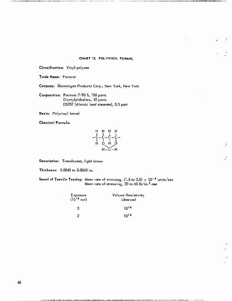
CHART 13. POLYVINYL FORMAL
Classification: Vinyl polymer
Trade Name: Formvar
Company: Shawinigan Products Corp., New York, New York
Composition: Formvar 7/90 S, 100 partsDioctylphthalate, 10 partsDS207 (dibasic lead stearate), 0.5 part
Resin: Polyvinyl formal
Chemical Formula:
H H H HI I I I
-C-C-C-C-I I I I
H 0 H 0\ /
H-C-H
Description: Translucent, light brown
Thickness: 0.0045 to 0.0060 in.
Speed of Tensile Testing: Mean rate of straining, (1.5 to 3.0) x 10-4 units/secMean rate of stressing, 20 to 60 lb/in. .see
Exposure Volume Resistivity(1018nvt) (ohm-cm)
0 1014
2 1014
pM<5<***ite«««i«Ni&f^

6V
n o 3 •o » 3- 5" o A a.
2-
5*
PER
CE
NT
OF
INIT
IAL
VA
LU
E*
c/
<l>
/
in -< SO
••O
CD
O r~
m/
i
OJ
//
'/>
Ja>
/>°7
•**l
ELONGATIOTHEINITIALOBTAINED1
PROPERTY*INITIALVALUETENSILESTRENGTH7400psiELONGATION2%ELASTICMODULUS5x105psic/
oc
o
—T
-o c <
NMANYTIMES.VALUEISNTHISREGION
C\,< m
r\J
SP
EC
IFIC
GR
AV
ITY
(25
/4°C
)
1
o h/1 /
ST
RE
SS
(psi
)
C -z.
;o
33
]
otJ
I> H m
o
oas
*
LT
J3D m > Z C
D
"D O Z -1
o ro
3
o."-.
•'O
Jro C
D
CH
AN
GE
INW
EIG
HT
(%)
jioj
roJ-
-»O
OO
OO
OO

50
CHART 14. CHEMICAL FORMULAS OF FILTER CLOTHS
0 0 HII II I
- C(CH2)4 - C- N- (CH2)6 - N-H
Nylon
H H H H HI I I I I
_C-C —C-C —C-II III
H CN H CN H
Orion
_CO-/ \-COOCH2CH20 -
Dacron

UNIRRADIATED IRRADIATED UNIRRADIATED IRRADIATED UNIRRADIATED IRRADIATED
Orion Dacron Nylon
Fig. 3.10. Filter Cloth Exposed to a Flux of 10|y nvtl_n

Chapter 4
DAMAGE BY RADIATION OTHER THAN REACTOR RADIATION
Most of the information on the radiation stabilityof polymers was obtained by using reactor radiation. However, it is important to know whetherthe data can be extrapolated to other kinds ofradiation. Since radiation damage to organicsolids results from ionization, it is to be expectedthat all types of ionizing radiation will causesimilar damage and that the extent of the damagewill be nearly proportional to the amount of energyabsorbed.
Gamma radiation interacts to produce electrons,which are ionizing particles. Fast neutrons areslowed by scattering, and in organic materials,the, energy released is transferred primarily tohydrogen nuclei (because of their large stoppingpower), and protons are formed which cause ionization in much the same manner as do the elec
trons from the gamma radiation. In organic materials which are damaged by ionizing radiation,damage due to displaced atoms is masked bydamage from ionization. Ionization damages theorganic compounds by breaking chemical bonds.
Thermal neutrons do appreciable damage to onlymaterials which contain elements with high thermalneutron cross sections. The thermal neutron-
produced damage is due both to ionizing radiation(to gammas and betas emitted in the absorptionprocess) and to the recoil of the atoms which emitradiation.
In Tables 4.1 through 4.4, the changes producedby other types of radiation are compared withchanges produced in hole 19 of the ORNL GraphiteReactor (at a power level of about 3600 kw, theenergy absorbed from both fast-neutron and gammaradiation by polyethylene in hole 19 is 3.5 x 10rep/hr). The other types of radiation employedwere reactor radiation with the gamma componentincreased eightfold and the fast-neutron componentunchanged (1.0 x 10 rep/hr), radiation from aCo source at 10 , 10 , and 10 rep/hr, and radiation from a Au source (log mean level of2 x 104 rep/hr).
The method used for calculating the intensityof the reactor radiation has been described (7).Energy absorption from both fast neutron andgamma radiation is taken into account. The intensity of radiation from the Au and Cosources was measured with ionization chambers.
The calibration of the ion chambers was checked
52
at about 10 rep/hr by comparison with Victoreenroentgen meters. At the higher intensities, theion chamber was checked for saturation by varyingthe voltage across the electrodes. There was novoltage dependence for the current.
REACTOR EXPOSURE WITH GAMMA
INTENSITY INCREASED WITH CADMIUM
If test specimens are wrapped in cadmium duringexposure in the reactor, the gamma flux is increased by the Cd1'3(n,y)Cd114 reaction over thatnormally present. If it is assumed that all damageby reactor radiation results from fast-neutron andgamma radiation and that the damage by each isproportional to the energy absorbed by the sample,then the equivalent damage (or energy absorbed)is
(N + G})a = (N + G2)b ,
and the ratio of the exposure (in nvt) withoutcadmium to the exposure within a cadmium enclosure that produces the same change is
N + CG,
N + G
where
N = energy absorbed from fast neutrons,G. = energy absorbed from gammas without
cadmium,G„ = energy absorbed from gammas with cad
mium (G„ = CG,),a = exposure (nvt) for a given change without
cadmium,b = exposure (nvt) for the same change with
cadmium,C = G2/Gv
Now by lettingnvt.
b nvtCd
and
then
(1) y =
N
x + C
x + 1

TABLE 4.1. INCREASE IN EFFECTIVENESS OF EXPOSURE OBTAINED WITH CADMIUM
PROPERTY
CHOSEN FOR
STUDY
BEFORE
IRRADIATION
AFTER
IRRADIATION
EXPOSURE
WITH Cd
(10,S nvt)
EXPOSURE
WITHOUT Cd
TO PRODUCE
EQUIVALENT
CHANGE
(10 vt)
EXPOSURE
RATIO
WITHOUT Cd
WITH Cd
1. Methyl methacrylate
polymer Tensile strength, psi 8,000 3000 to 5000 0.018 0.043 to 0.049 2.4 to 2.7
Elongation, % 2 to 5 0.9 to 1.4 0.018 0.03 2
2. Monofluorotrichloro-
ethylen©
Impact strength,
ft-lb/in. of notch
1.7 0.4 to 0.8 0.018 0.06 to 0.07 3 to 4
3. Teflon Specific gravity,
25/4°C
2.17 2.20 0.018 0.07 4
4. Polyvinyl chloride
(Saran B-115) Shear strength, psi 2,900 1600 0.13 0.22 1.7
Rockwell hardness •R 76
a 20
R 25
a -90
0.13 0.22 1.7
5. Polyvinyl chloride
acetate Tensile strength, psi 10,000 7500 to 7600 0.23 0.39 1.7
Rockwell hardness R 122
a 104
R 111
a 91
0.23 0.39 1.7
6. Phenol formaldehyde
resin (no filler)
Impact strength,
ft-lb/in. of notch
0.53 0.24 to 0.27 0.23 1.1 5
7. Phenol formaldehyde
resin (paper base) Shear strength, psi 12,000 6000 to 6500 0.13 0.6 5
8. Phenol formaldehyde
resin (paper
Rockwell hardness R 122
a 1T5
R 10
a M0
2.2 >8 >4
laminate)
9. Urea formaldehyde Shear strength, psi 10,000 3500 to 4000 0.13 0.6 5
resin (cellulose
filler)
10. Allyl diglycol
carbonate polymer Rockwell hardness R 119
a 90
R 8
a -140
2.2 4 to 6 2 to 3
11. Polyethylene Impact strength,
ft-lb/in. of notch
11.2
11.2
6.1
3.0
0.13
0.23
0.32
0.70
2.5
3.1
12. GR-S 50 Elongation, % 260 to 280 180 to 200 0.018 0.060 3.3
Durometer hardness 67 75 0.018 0.042 2.3
13. Hycar OR-15
(32A45) Tensile strength, psi 1,900 2500 0.13 0.4 3
Elongation, % 220 to 230 30 0.13 0.60 4.6
Durometer hardness 78 96 0.13 0.4 3
14. Hycar PA-21 Tensile strength/ psi 2,000 700 0.13 0.6 5
Elongation, % 330 40 0.13 0.60 4.6
Durometer hardness 65 83 0.13 0.8 6
15. Natural rubber
(32A43) Tensile strength, psi 2,600 1700 0.13 0.35 3
E longation, % 400 140 0.13 0.45 3.5
Durometer hardness 68 78 0.13 0.2 2
16. Neoprene W (32A44) Elongation, % 400 to 500 215 to 230 0.018 0.04 2
17. Silastic 7-170 Elongation, % 60 to 100 30 to 35 0.018 0.065 4
Durometer hardness 60 72 0.018 0.03 2
18. Thiokol ST (3000ST) Tensile strength, psi 800 to 900 200 to 400 0.23 1.5 6.5
Elongation, % 150 40 0.23 1.5 6.5
Durometer hardness 75 65 0.23 >2 >8
53

In Table 4.1, the exposure (in nvt) required toproduce a given property change is compared withand without cadmium for a number of plastics andelastomers. In Fig. 4.1, x vs. y, as defined inEq. 1, is plotted for each of the materials listed;y is the ratio of the exposures taken from Table
4.1, and x is calculated from the calorimetricdetermination of the energy absorbed from fast-neutron and gamma radiation (2) by the elements.A sample calculation for polyethylene has beengiven (7). (The compositions of the elastomersare given in Table 1.1, with the exception of
TABLE 4.2. COMPARISON OF THREE LEVELS OF INTENSITY OF RADIATION FROM A Co60 SOURCE WITHTHE ORNL GRAPHITE REACTOR IN THE DAMAGE PRODUCED IN ELASTOMERS
ELASTOMER
TENSILE
STRENGTHELONGATION
(%)
SHORE
DUROMETER
(psi) HARDNESS
Natural rubber (32A43)
a 2900 430 68
b 2600 370 72
c 2300 280 72
d 2600 360 72
e 2700 380 70
Neoprene W (32A44)
a 2800 460 87
b 1700 130 88
c 1300 50 85
d 1800 80 92
e 2200 130 90
GR-S 50 (32A47)
a 1700 240 70
b 1500 140 77
c 1050 50 83
d 1200 80 82
e 1200 95 77
Thiokol ST (3000ST)
a 750 130 75
b 770 105 78
c 580 95 76
d 730 105 74
e 800 100 80
Silastic 7-170
o 430 90 60
fa 490 35 76
c 510 20 83
d 550 30 81
e 600 40 80
(a)
Exposed in the ORNL Graphite Reactor for 0.07 X 10'8 nvt (for materials of about this hydrogen content the leveof intensity of ionizing radiation is 2 X 10 rep/hr and the dosage is 5 X 10 rep),
(c)
No irradiation.
,18
60Exposed to a Co source at a level of intensity of 1.4 X 10 rep/hr for a dosage of 6 X 10 rep.( 'Exposed to a Co60 source at 2.0 X10⁵ rep/hr for 8X10⁷ rep.(e'Exposed to a Co60 source at 2.3 X10⁴ rep/hr for 3.6 X10⁷ re
54
i^«lWlkJ4^^^^««#a*iS*il«^»>4S^--^KM*w-,i*«i*JiB •

TABLE 4.3. COMPARISON OF DAMAGE PRODUCED BY Co60 GAMMA RADIATION AND REACTOR RADIATION
TENSILE
STRENGTH
(psi)
ELONGATION
(%)
ELASTIC
MODULUS
(105 psi)
DUROMETER
HARDNESS
Plastics
ROCKWELL HARDNESS
a Scale R Scale
SPECIFIC
GRAVITY,
25/4°C
Allyl diglycol
carbonate
polymer
(CR-39)
a 6000 3 3.3 90 112 1.318
b 6000 3 2.7 80 102 1.290
c 1.5 0.6 0.6 2.1
Linen fabric
bakelite
(phenolic)
a 12000 4 10 114 to 116 123 1.340
b 6000 0.5 10 112 to 116 122 1.337
c 0.7 0.7
Unfilled
phenoli c
(Catalin)
a 5500 1 6.0 109 123 1.300
b 5500 1 4.2 105 119 1.303
c 1.6 1.0 0.3
Nylon
(FM-10001)
o 8900 40 3.2 86 103 1.135
b 8800 30 2.5 88 106 1.136
c 1.1 1.1
Royali te
a 4000 >10 2.6 70 89 1.113
b 6000 9.1 3.8 78 96 1.124
c 1.2 1.2 1.2 0.7 1.4 0.6
Elastomers
Natural rubber
(32A43)
a 2600 420 62 1.186
fa 1400 100 79 1.196
c 1.2 0.8 0.6 0.8
Neoprene W
(32A44)
a 2900 450 79 1.418
b 1800 20 92 1.428
c 1.2 3 3
55

TABLE 4.3. (continued)
TENSILE
STRENGTH
(psi)
ELONGATION
(%)
ELASTIC
MODULUS
(105 psi)
DUROMETER
HARDNESS
ROCKWELLHARDNESS
a Scale R Scale
SPECIFIC
GRAVITY,
25/4° C
Elastomers
Hycar OR-15
(32A45)
o 1900 250 74 1.229
b 4200 35 97 1.261
c 0.5 0.8 0.7 1.0
GR-S 50
(32A47)
a 1700 270 69 1.210
b 1600 40 90 1.220
c 1.7 1.7 1.0 0.4
Thiokol ST
(3000 ST)
o 800 160 74 1.450
b 700 80 74 1.454
c 2.5
Silastic
7-170
a 520 95 59 1.382
b 680 7 93 1.396
c 0.7 0.7 1.4
(a)Before irradiation.
(fa) After 2.8 X10⁹rep from Co60.Ratio of energy absorbed from Co to the energy absorbed in the reactor for an exposure in the reactor which
produces the same value of the physical property as listed in (b).
Silastic, tor which the proportion of filler materialwas not known; the composition of unfilled polymers was calculated from their chemical structural
formulas.) When C is taken as 8, the curve ofFig. 4.1 is given by Eq. 1. This curve gives thebest fit for the experimental points. It followsthen that the energy absorbed from gamma radiation has been increased eightfold.
The sensitivity of determining the y values ofFig. 4.1 depends on the rate of change of theproperty chosen for study. When more than oneproperty is studied, the agreement shown in Table4.1 indicates that the damage produced with cadmium is similar in nature to that produced withoutcadmium. This implies that the damage produced
56
by gamma radiation is similar to that produced byfast neutrons.
The cadmium-produced damage increase will notbe so great for materials in which appreciabledamage results from thermal neutrons, since cad-rruum screens out the thermal neutrons. Since
fluorine and chlorine have high cross sectionsfor thermal neutrons, additional damage for materials which contain these elements comes from
beta radiation and recoil atoms resulting from theabsorption of thermal neutrons. For the materialswhich contain chlorine or fluorine (fluorothene,Teflon, Saran, Neoprene W, and vinyl chlorideacetate polymer) the experimental points fallbelow the curve, since the thermal neutron-produced damage was not taken into account.
s# ^*i^ii**f*^a<fc-j*$**ftii£v. &s+ &*f&^,^Ai$i>tli>i&$*4&K-m*m*<c**'*- •••
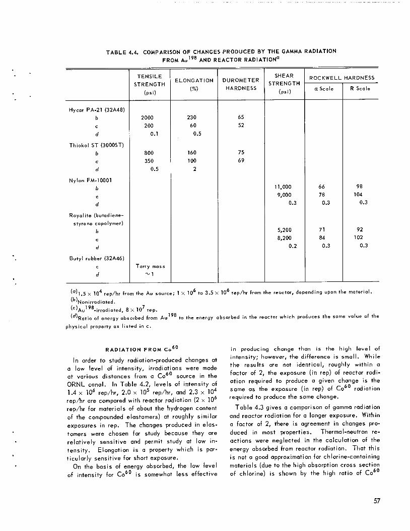
TABLE 4.4. COMPARISON OF CHANGES PRODUCED BY THE GAMMA RADIATION
FROM Au198 AND REACTOR RADIATION"
TENSILE
STRENGTH
(psi)
ELONGATION
(%)
DUROMETER
HARDNESS
SHEAR
STRENGTH
(psi)
ROCKWELL HARDNESS
a Scale R Scale
Hycar PA-21 (32A48)
b 2000 230 65
c 200 60 52
d 0.1 0.5
Thiokol ST (3000ST)
b 800 160 75
c 350 100 69
d 0.5 2
Nylon FM-10001
b 11,000 66 98
c9,000 78 104
d 0.3 0.3 0.3
Royalite (butadiene-
styrene copolymer)
b 5,200 71 92
c8,200 84 102
d 0.2 0.3 0.3
Butyl rubber (32A46)
c Tarry mass
d ~1
(°'l.5 X104 rep/hr from the Au source; 1X10⁶ to 3.5 X10⁶ rep/hr from the reactor, depending upon the material.(b).Nonirradiated.
(c)Au198-irradiated, 8 X10⁷ rep.'̂ Ratio of energy absorbed from Au198 to the energy absorbed in the reactor which produces the same value of the
physical property as listed in c.
60RADIATION FROM Co
In order to study radiation-produced changes ata low level of intensity, irradiations were madeat various distances from a Co source in the
ORNL canal. In Table 4.2, levels of intensity of1.4 x 106 rep/hr, 2.0 x 10⁵ rep/hr, and 2.3 x 10⁴rep/hr are compared with reactor radiation (2 x 10rep/hr for materials of about the hydrogen contentof the compounded elastomers) at roughly similarexposures in rep. The changes produced in elastomers were chosen for study because they arerelatively sensitive and permit study at low intensity. Elongation is a property which is particularly sensitive for short exposure.
On the basis of energy absorbed, the low levelof intensity for Co60 is somewhat less effective
in producing change than is the high level ofintensity; however, the difference is small. Whilethe results are not identical, roughly within afactor of 2, the exposure (in rep) of reactor radiation required to produce a given change is thesame as the exposure (in rep) of Co radiationrequired to produce the same change.
Table 4.3 gives a comparison of gamma radiationand reactor radiation for a longer exposure. Withina factor of 2, there is agreement in changes produced in most properties. Thermal-neutron reactions were neglected in the calculation of theenergy absorbed from reactor radiation. That thisis not a good approximation for chlorine-containingmaterials (due to the high absorption cross sectionof chlorine) is shown by the high ratio of Co
57

or3
oo
OQ.
XUJ
QLU
00 c
31o
o
LU
I
2
Q<
^
enLU
O
z<Xo
3orLU
? 0.
n o
<o
or0.
H
O
t-
LU1
J_ <T1— >
5 3rj
LU hior3 0000 LU
o O0- 3
X QLU O
rrLl. nO
O o
t? X
or
12
1 1
10
UNCLASSIFIEDDWG. 21556
• MATERIALS WITH LOW THERMAL-NEUTRON CROSS SECTIONS
O FLUORINE- OR CHLORINE-CONTAINING MATERIALS
Y= j^ WHEN C=B
NUMBERS REFER TO THE MATERIALS LISTED IN TABLE 4.1
0 1.0 2.0 3.0 4.0 5.0
RATIO OF ENERGY ABSORBED FROM FAST NEUTRONS TO ENERGY
ABSORBED FROM GAMMA RADIATION WITHOUT CADMIUM, X= -pL
Fig. 4.1. Increase in Effectiveness of Exposure Obtained with Cadmium.
radiation to reactor radiation exposure obtainedfor Neoprene W. The energy absorption of thematerials, relative to polyethylene in the reactor,is given in Table 7.1.
The Co source and the reactor give approximately similar results, and this indicates that
Co can be used in future radiation-stabilitystudies with organic materials. The advantagesof Co over the reactor include less limitation
as to the size of specimens and no problem asto induced radiation (Co irradiation space islimited at present).
58
4= JjaSlM^^W-aJftjMM.J^

RADIATION FROM Au198
A Au source with a log mean level of intensity of 1.5 x 10⁴ rep/hr was also employed inirradiations. Since the half life of the source is
only 2.7 days, it was replaced with a freshlyactivated source once every week. In Table 4.4,
changes induced by Au radiation are comparedwith changes induced by reactor radiation. Thereappears to be somewhat greater damage for Auradiation than for reactor radiation. Further studyis required before the significance of this difference can be explained.
Chapter 5
EFFECT OF OXYGEN AND THE TIME OF AGING AFTER IRRADIATION
For many organic liquids, the radiation damage isgreater if the material is irradiated in the presenceof oxygen (72). As discussed in Chapter 2, no improvement in resistance was gained by the inclusionof an antioxidant in elastomer formulations. To
study further the effect of oxygen, plastics andelastomers were irradiated in the absence of oxygen.
Duplicate sets of specimens were irradiated —first, in cans containing an atmosphere of pureoxygen and second, in cans containing an atmosphere of pure helium. Except for slight surfacedarkening in some materials which were irradiatedin oxygen, no appreciable difference could be detected in radiation stability between materialsirradiated in oxygen and those irradiated in heliumatmospheres. The physical properties of materialsirradiated in helium and in oxygen are shown inTable 5.1. Further evidence that the presence ofoxygen does not greatly affect the mechanicalproperties of specimens of this thickness is shownby the agreement obtained (Chapter 1) between theradiation stability of Group I elastomers which wereirradiated in air and Group II elastomers whichwere irradiated in helium.
None of the elastomers were stressed duringirradiation in the above tests. Since ozone attacks
only stressed elastomers, there was no ozonedamage (see Chapter 1).
It is conceivable that during the irradiation of amaterial, decomposition products might be formedwhich would continue to degrade the material as itaged after irradiation. To see whether such processes occur, specimens of the elastomers andplastics were irradiated and some of their physicalproperties were measured at various aging timesafter irradiation. Since the physical properties ofmany of these materials change with time whetheror not they have been irradiated, a nonirradiatedspecimen was observed along with each irradiatedspecimen. No aging change was detected in moderately damaged specimens. Some severely damagedspecimens continued to change after removal fromthe radiation field, but the change was small incomparison with the initial radiation damage;neither appreciable radiation-induced aging norpostradiation healing was detected in any of thesematerials.
59

TABLE 5.1. PROPERTIES OF PLASTICS AND ELASTOMERS IRRADIATED IN OXYGEN AND IN HELIUM
MATERIALEXPOSURE
(1018 nvt)PROPERTY CHOSEN
FOR STUDY
Plastics
BEFORE
IRRADIATION
AFTER
IRRADIATION
IN HELIUM
AFTER
IRRADIATION
IN OXYGEN
Methyl metbacrylate 0.19 Shear strength, psi 8000 2000 2200
polymer Impact strength,ft-lb/in.
of notch
0.34 0.19 0.19
Vinyl chloride acetate 0.05 Rockwell hardness R 122 R 117 R 117
polymer a 104 a 101 a 101
Cellulose acetate polymer 0.19 Shear strength, psi 6000 to 6500 2500 2500
Impact strength, ft-lb/in. 1.1 to 1.6 0.20 0.20
of notch
Monochlorotrifluoroethylene 0.19 Shear strength, psi 5000 to 5500 2000 1700
polymer Impact strength, ft-lb/in.
of notch
1.6 to 1.7 0.35 0.35
Nylon FM-1 2.3 Rockwell hardness R 105 R 118 R 118
a 65 a 85 a 85
Polyethylene 2.3 Shear strength, psi 2200 1600 1600
Rockwell hardness R -20 R 90 R 90
a -150 a-70 a-70
Plaskon alkyd 2.3 Impact strength, ft-lb/in.
of notch
0.4 0.4 0.4
Styron 475 2.3 Impact strength, ft-lb/in.
of notch
0.5 0.2 0.2
Elastomers
GR-S 50 (32A47) 0.61 Durometer hardness 69 73 73
Hycar PA-21 (32A48) 0.61 Durometer hardness 62 78 78
Hycar OR-15 (32A45) 0.61 Durometer hardness 75 100 100
Natural rubber (32A43) 0.61 Durometer hardness 60 80 80
Neoprene W (32A44) 0.61 Durometer hardness 80 98 98
Silastic 7-170 0.61 Durometer hardness 59 95 95
Thiokol ST (3000ST) 0.61 Durometer hardness 74 64 64
60

Chapter 6
RADIATION-INDUCED CHANGE IN THE SPECIFIC VOLUME
For most materials which are hardened by radiation, the specific volume change can be correlated with radiation exposure. Certain materialsshow no uniform change in either hardness orspecific volume. For these materials, it is assumed that the effect of chain cleavage masks thechange in specific volume and hardness whichotherwise would be produced by cross-linking.
Most materials which are increased in hardness
by radiation show a decrease in specific volume.There are insufficient data available for longirradiation periods to give precise values, butwithin the accuracy obtained, the experimentallydetermined values of specific volume may be fittedto the first-order rate equation
(l) v, - V (^0 - Vc [exp (-kR)]
whe
the specific volume at 25°C, cm /g;R - the irradiation period, 10 nvt;
V0 — the specific volume before irradiation at25°C, crnVg;
V = the limiting specific volume approachedfor long periods of irradiation, cm /g (aconstant for the material);
k = a constant for the material, 1/(10 8 nvt).For small values of R, the relationship between
the specific volume and the irradiation period isnearly linear. This is predicted by Eq. 1 sincefor small values of R, exp (—kR) is approximately(1 - kR) and Eq. 1 becomes
(2) VR = V„ lyo - V ) kR
In Table 6.1 the constant of Eq. 2 (VQ - Vjjkis listed for the materials studied which show auniform decrease in specific volume. Some of theelastomers were irradiated for periods sufficientto estimate V in order to calculate k. For polyethylene and polystyrene, the value of V'x isestimated from other data (10,11).
61

TABLE 6.1. RADIATION-INDUCED CHANGE IN THE SPECIFIC VOLUME*
SPECIFIC VOLUME AT 25°C (cm3/g)
(cm3/g-1018nvt)
k
MATERIAL Initial Value,
V0
Saturated Value,[1/(1018 nvt)]
Natural rubber
(32A43) 0.8480 0.7900 0.016 0.27
(P1S1C9) 0.9569 0.018
Plasticized natural rubber
(P1S2C1) 0.9634 0.017
(P1S2C2) 0.9542 0.018
(P1S2C3) 0.9560 0.015
(P1S2C4) 0.9141 0.017
(P1S2C5) 0.8474 0.014
(P1S2C6) 0.9009 0.017
Polybutad iene
(P1S1C1) 0.9640 0.033
Hycar OR
(32A45) 0.8130 0.7580 0.025 0.45
(P1S1C2) 0.8912 0.032
GR-S 50
(32A47) 0.8280 0.7680 0.018 0.30
Hycar OS-10
(P1S1C3) 0.8958 0.017
Hycar PA-21
(32A48) 0.7883 0.7565 0.0032 0.10
(P1S1C5) 0.8217 0.012
Neoprene W
(32A44) 0.7060 0.6810 0.018 0.72
(P1S1C5) 0.7438 0.016
Neoprene GN
(P1S1C4) 0.7340 0.7160 0.022 1
Silastic 7-170 0.7250 0.6400 0.014 0.16
Silastic 250
(P1S1C8) 0.8300 0.025
Vulcollan 0.8084 0.003
Polyethylene 1.097 0.88 0.005 0.04
Polystyrene
(Amphenol) 0.9523 0.82 0.001 0.01
(Styron 637) 0.9540 0.82 0.001 0.01
(Styron 671) 0.9525 0.82 0.001 0.01
*Parameters of Eqs. 1 and 2.
62

Chapter 7
RADIATION-INDUCED GASSING
Small pieces (0.2 to 0.5 g) of elastomers andplastics were sealed in glass capsules and irradiated. The capsules were broken open, and thevolume of gas evolved was measured over mercury.
Inthe range from about 1 to 50 ml, the gas evolvedis proportional to the exposure in nvt for the materials listed in Table 7.1, except for polyvinylformal and materials which evolve less than 0.2
ml/g*1018 nvt. The gas evolved by polyvinyl formalis proportional to the square root of the nvt. Forthe other materials, the value listed in Table 7.1is the slope of the linear portion of the plot of thevolume of gas per gram of polymer vs. nvt. In thecase of polyvinyl formal, the value listed is thegas evolved at 10 nvt. Only one measurementwas available for materials which evolved less gasthan0.2 ml/g-1018 nvt because ofthe long exposureperiod required to obtain measurable quantities ofgas; therefore it is not certain, for these materials,whether the quantity of gas evolved is proportionalto exposure.
In Table 7.1, the yields are also expressed asmolecules of gas per 100 ev of energy absorbed.The amount of energy absorbed by materials irradiated in a reactor is highly dependent upon thehydrogen content, since hydrogen has a high stopping power for fast neutrons. The energy absorption was calculated from the composition of thematerials by using calorimetrically determinedvalues of the elements. The calculation for polyethylene given (1) illustrates the method.
In Table 7.2, certain representative polymers arelisted in order of the amount of gas produced byradiation. The ranking of the solid polymers withregard to gassing is similar to the ranking whichhas been found for liquids with similar chemicalstructures (72,13). This is in contrast to theranking based on change in mechanical properties(cf. "Discussion of Results," this report) whichbears no direct relation to the ranking based ongas evolution.
Evolution of hydrogen gas results from the radia-ation-produced cross-linking of polyethylene;evolution of light hydrocarbons results from chain cleavageof polyethylene molecules. Since hydrogen diffuses with ease through the polymer, the volume ofgas produced is proportional to the weight of thespecimen; since hydrocarbons diffuse with difficulty, the volume of gas is approximately propor
tional to the area. For polyethylene specimens ofabout 5 to 10 cmVg of specific area, the composition of the gas has been reported to be about98% hydrogen and 2% hydrocarbons (4).
Organic liquids with unsaturated structuresevolve less gas than liquids with saturated structures (73). This may be attributed to the absorption of hydrogen or hydrocarbons at double bonds.Very low rates of gas evolution are given by liquidswith aromatic structures. This may be attributedboth to unsaturation and to high stability of thearomatic structure which permits it to dissipateradiant energy without decomposition. In theserespects, the gassing of organic solids is similarto that of liquids.
The gassing rate of polyethylene plastic is of thesame order as that of the paraffin oils which alsohave the chemical structure (CH,) . The physicalstate, then, would seem to affect the gassing rateless than the chemical structure. It is likely thatthe low values obtained for some of the paraffinoils are due to the presence of small amounts ofunsaturated compounds. Highly refined mineral oilshows nearly the same rate of gassing as doespolyethylene.
Hycar PA-21 is a saturated elastomer whichshows a rate of gassing similar to that of polyethylene. Its structural formula is similar to thatof polyethylene except for the replacement, by asubstituent group, of one of the hydrogen atomsattached to every other carbon atom. Since the rateof gassing and the rate of increase in hardness anddecrease in specific volume are similar to the ratefor polyethylene, the rate of radiation-inducedcross-linking is evidently little affected by thissubstitution. Hycar PA-21 crumbles after very longexposure, unlike polyethylene and many other elastomers which break with a conchoidal fracture after
long exposure. The crumbling is thought to resultfrom decreased resistance to chain cleavageproduced by the substituent group.
Butyl rubber and polymethyl methacrylate, whichhave both hydrogen atoms attached to every othercarbon atom replaced by substituent groups to formquaternary carbon atoms, show low resistance tochain cleavage, as is evidenced by deteriorationin strength for exposure periods which are too shortto harden polyethylene. It is thought that most ofthe gassing of these polymers results (as for poly-
63

TABLE 7.1. YIELD OF GAS PRODUCED BY REACTOR IRRADIATION OF PLASTICS AND ELASTOMERS
MATERIALGAS EVOLVED
(ml/g-1018 nvt)
Plastics
ENERGY
ABSORPTION*
YIELD
(molecules/100 ev)
Allyl polymer
Trial lyl cygnurate 0.5 0.7 0.04
Acrylic polymer
Methyl methacrylate polymer 12 0.7 0.9
Amino resins
Aniline formaldehyde polymer 0.3 0.7 0.02
Melamine formaldehyde polymer (cellulosic filler) 4.0 0.6 0.3
Urea formaldehyde polymer (cellulosic filler) 6.0 0.6 0.5
Casein plastic 2.6 1 0.1
Cellulosics
Cellulose acetate 6.8 0.7 0.5
Cellulose acetate butyrate 11 0.7 0.8
Cellulose propionate 13 0.7 1.0
Cellulose nitrate 41 0.7 3.0
Ethyl cellulose 13 0.7 1.0
Ethylene polymer
Polyethylene 38 1.0 2.0
Furane resin (asbestos and carbon filler) <0.05 ~0.4 <0.01
Nylon FM-3003 11 0.8 0.7
Phenolics
No filler 1.1 0.7 0.08
Cellulosic filler
Linen fabric 4.7 0.7 0.5
Paper base 6.0 0.7 0.5
Paper laminate 6.0 0.7 0.5
Mineral filler
Asbestos fabric <0.05 ^0.3 <0.01
Asbestos fiber <0.05 ^0.3 <0.01
Asbestos (Haveg 41) <0.05 ^0.3 <0.01
Graphite (Karbate) <0.01 ~0.4 <0.001
Polyester resins
Allyl diglycol carbonate polymer 21 0.9 1.2
Plaskon alkyd 1.1 0.5 ~0.05
Selectron 5038 3.4 0.7 0.3
Mylar film 1.2 0.7 0.09
Silicone plastics
Silicone tape 10
Silicone-varnished glass laminate 7
64

TABLE 7.1. (continued)
MATERIALGAS EVOLVED
(ml/g- 1018 nvt)ENERGY
ABSORPTION*
YIELD
(molecules/100 ev)
Plastics
Styrene polymers
Polystyrene (Amphenol) 0.1 0.7 0.008
Styrene-butadiene copolymer (Royalite) 0.8 0.8 0.01
Pliotuf 0.15 0.8 0.01
Vinyl polymers
Polyvinyl formal 37 0.7 2.8
Elastomers
Natural rubber (32A43) 2.7 0.6 0.2
Natural rubber with asbestos filler (17FBB194) 1.1 0.5 0.11
Natural rubber with dibutyltin dilaurate (17FBB197) 3.5 0.6 0.3
Natural rubber with dodecyl mercaptan (16RCB1) 2.8 0.6 0.2
Natural rubber—butyl rubber mixtures
50:50 (17FBB198) 4.5 0.6 0.4
25:75 (17FBB199) 5.4 0.6 0.5
10:90 (17FBB200) 6.0 0.6 0.5
Natural rubber with butyl reclaim (17FBB201) 4.5 0.6 0.4
Butyl rubber, GR-I 50 (32A46) 6.6 0.7 0.5
GR-S 50 (32A47) 1.3 0.6 0.11
Hycar OR-15 (32A45) 1.7 0.6 0.14
Hycar PA-21 (32A48) 9.3 0.6 0.8
Neoprene W(32A44) 1.0 0.5 0.10
Neoprene W with dodecyl mercaptan (17FBB196) 1.1 0.5 0.11
Silastic 7-170 7.0 0.6 0.6
Thiokol ST (3000ST) 1.3 0.4 0.17
Vulcollan 8.1 0.6 0.7
'Relative to polyethylene.
ethylene) from cross-linking. The somewhat lowerrate of gassing (than that for polyethylene) mayresult from a larger portion of the energy absorbedfrom radiation going into chain cleavage. (It wasobserved above that for polyethylene the gas evolvedfrom cross-linking greatly outweighs the gas fromchain cleavage.)
That natural rubber cross-links like polyethyleneis evidenced by increased hardness and increasedspecific gravity. That the gassing is less than itis for polyethylene may be due to absorption of partof the hydrogen at double bonds.
Unfilled phenolic polymer, aniline formaldehydepolymer, and polystyrene have phenyl groups intheir
65

TABLE 7.2. RELATION OF GASSING TO CHEMICAL STRUCTURE
POLYMER MOLECULES/100 ev STRUCTURE
H H1 1
Polythene 2.01 1
-C-C-1 i
H H
Paraffin oils H H1 1
Light mineral oil (USP) 1.81 1
-c-c-1 1
H H
H H1 1
SAE 90 oil 1.31 1
-c-c-1 1
H H
H H1 1
SAE 10 oil 1.31 1
-c-c-1 1
H H
H H1 1
Light machine oil 0.81 1
-c-c-1 1
H H
H H1 1
Vacuum pump oil, heavy grade 0.61 1
-c-c-1 1
H H
H H1 1
Hycar PA-21 1.6
1 1
-c-c-
1 1H CO
1
0
1
C2H5
H CH,l l J
Butyl rubber 1.0i i
-C-C-1 1H CH3
H CH,l 1 J
Polymethyl methacrylate 0.9 -c-c-1 1
H CO1
0|
-
CH3
66

TABLE 7.2. (continued)
POLYMER MOLECULES/100 ev STRUCTURE
H CH, H H1 1 J l 1
Natural rubber 0.2ii ii
-C-C =c-c-1 1H H
0.08 <OH H1 i
Unfilled phenolic polymer AH
H1
Aniline formaldehyde polymer 0.02 -N-C-i
Ai
H
\A
H H1 |
Polystyrene ,1 0.0081 1
-C-C-i i
A H
V
structural formulas. The gassing rate of these polymers is of the same order as the rate of evolution of
hydrocarbons (due to chain cleavage)from polyethylene and is much less than the rate of evolution of
hydrogen (due to cross-linking) from polyethylene.The rate of decrease in specific volume and the rateof increase inelastic modulus are much less for polystyrene than for polyethylene. It is thought that alower rate of cross-linking is due to the presence ofthe phenyl group, which may function either to dissipate the radiant energy or to impose sterichindrance to cross-linking.
The phenolic polymer shows the greatest rate ofgassing and deterioration in strength of thesethree polymers which contain phenyl groups.Lowered resistance to chain cleavage may be dueto the presence of the phenyl groups connecteddirectly as part of the polymer chain.
Aniline formaldehyde polymer shows greater gassing and loss of strength than polystyrene. Thestructure of aniline formaldehyde polymer may bederived from that of polystyrene if part of thecarbon of the polymer chain is replaced by nitrogen.
This substitution is thought to result in loweredresistance to chain cleavage.
The gassing rate of polystyrene is less than therate of hydrocarbon evolution of polyethylene.Measurements for polystyrene were made for onlyone exposure period, since relatively long exposureis required to produce measurable quantities of gas.It is therefore uncertain whether the gassing isproportional to the radiation exposure. It is notknown how the rates of diffusion of hydrocarbonsin polystyrene and polyethylene compare. For thesereasons, it is not altogether certain that polystyreneis more resistant to chain cleavage than polyethylene; however, the very low gassing rate andthe low rate of change in specific volume show alow rate of cross-linking for polystyrene.
Mixtures of polystyrene and styrene-butadienecopolymer (Pliotuf and Royalite plastics), whichare softer and more flexible than unmodified polystyrene, show a rate of hardening (likely due tocross-linking) of the same order as the rate ofhardening of polyethylene; however, the rate ofgassing is much lower than the rate of gassing of
67

polyethylene. The low gassing rate may be due tothe absorption at double bonds of part of thehydrogen from cross-linking.
Lower gassing rates are given by mineral-filledphenolic, alkyd, and melamine plastics than by unfilled phenolic, alkyd, and melamine polymers, but
the rate is not greatly changed when the amount ofmineral filler is increased in elastomers. The
mineral filler may function to stabilize the hardmaterials by dissipating energy which would otherwise damage the polymer. This evidently does notoccur in soft materials.
DISCUSSION OF RESULTS
Most irradiations were conducted in the maximum-
flux region of the ORNL Graphite Reactor, wherethermal-neutron, fast—neutron, beta, and gammaradiation are present. Beta radiation results fromabsorption of thermal neutrons by the samplecontainer and by elements which are present in theplastics and elastomers. For most of the materialstested, the absorption coefficient for thermalneutrons is low enough so that the major portion ofthe damage comes from fast-neutron and gammaradiation. The product of the thermal-neutronflux in neutrons/cm -sec and the exposure time inseconds, the nvt, is used to measure the radiationexposure, since it is readily measured by theactivation of cobalt foils. The neutron-flux spectrum is given in an ORNL report (2).
For materials of the composition (CH.) , calorimetric measurement (3) of the energy absorbedfrom both fast-neutron and gamma radiation gives1.0 x 10 rep in an exposure of 1.0 x 10 nvt.Of this, about 70% is from fast-neutron radiationand 30% is from gamma radiation (7).
Similar effects for both fast-neutron and gamma
radiation are to be expected for organic materialswhich are damaged by ionizing radiation. Protonsejected from hydrogen atoms by fast neutrons causeionization and excitation of atoms in their path ina manner similar to that of secondary electronsproduced by gamma radiation.
Although most of the changes in physical properties described here were produced in the maximum-flux region of the ORNL Graphite Reactor, a numberof comparative studies were made with other typesof radiation. The sources of neutron-free gammaradiation that were used included Co (photonsof 1.25-Mev average energy) and Au (0.3-Mevphotons), which were produced by the activation ofgold and cobalt in the reactor. Qualitatively, thechanges produced by gamma radiation and reactorradiation are the same. Quantitatively, within asensitivity of about a factor of 2, equivalent changes
68
are produced in many properties for the same energyabsorption by both types of radiation. The lowsensitivity is partly the result of poor statisticsdue to the small number of samples which wereirradiated with the gamma sources (limited irradiation space was available) and possibly the resultof energy dependence of the radiation-producedchanges. Because of the limited irradiation spaceavailable, exposures to gamma radiation employedin the study were less than 10 rep.
The level of intensity of radiation from Co wasvaried from 104 to 106 rep by shielding the sourcewith water. Within this range, no pronouncedintensity effect was detected, but the changesproduced were dependent upon the total energyabsorbed. The level of intensity employed for theAu198 irradiations was not varied, since it wasvery low. (The half life of Au198 is very short;therefore it was necessary to replace this sourceonce a week with a freshly irradiated source. Thelog mean intensity was about 2 x 10 rep.)
The most intense source of radiation employedwas obtained by wrapping in cadmium the materialswhich were irradiated in the reactor. TheCd (n,y)reaction with thermal neutrons produces gammaradiation in addition to that which is normallypresent in the reactor. The total energy absorptionboth from fast-neutron and gamma radiation isincreased three- to eightfold by the cadmium, depending upon the composition of the material.
With most materials, irradiations conducted inoxygen and in helium gases give similar changes.(An exception is stretched rubber, which showsmore damage in oxygen because of ozone attack.)
Ionizing radiation produces changes in organicmaterials by breaking the chemical bonds betweenatoms. If the broken bond is in the main polymerchain, chain-cleavage results. If the broken bondsare between carbon atoms of the main chain and
attached side atoms or groups which are not connected directly in the main chain, either unsatu-
ji.ii:^^,^JJ>i3&$!!<BM$4$tt>t> i-...;

ration or cross-linking between adjacent polymerchains may result.
For polyethylene plastic, which has the structureof the unsubstituted paraffin chain, (CH,) , cross-linking rather than chain cleavage is the predominant process. This is evidenced by increase inhardness, tensile strength, and density (7,4).
Certain other polymers are observed to losestrength and to become either soft or brittle whensubjected to radiation exposures too short toproduce much change in polyethylene. In mostinstances, the rate of gas evolution of thesematerials is even less than it is for polyethylene.The hardness is either decreased or little changed,and there is small change in density. The mostpronounced change is a decrease in tensile strength.It is speculated that the mechanism for damage ofpolymers which show radiation stability of lowerorder than that of polyethylene is predominantly bychain cleavage.
Other linear polymers may be considered to havethe paraffin-chain structure of polyethylene, butwith substitutions. This outlook offers the advantage that the effect of the substituted groupson radiation stability may be determined by comparing the stabilities of the other plastics withthe stability of polyethylene. In Chart 15, thechemical groupings present in the polymers studiedare ranked in order of radiation stability. Theranking is not precise. There is often uncertaintyas to the relative order of groupings which rankclose together; however, a very large differenceexists in the stability of groupings which arespaced far apart. A discussion of the determinationof the stability of the groupings follows.
Group a is the repeating unit in the structuralformula of polystyrene. Polystyrene shows thebest stability of all the unfilled polymers tested.A comparison of group a with group b suggeststhat the greatly increased stability of polystyrene
CHART 15. CHEMICAL GROUPINGS RANKED IN ORDER OF RADIATION STABILITY
H HI I
•C-C-
H
(a)
OH
(g)
c-o-
H1
OH1
/l"
1
C1 \
/ OH h\\
c c
HN\l /
1
\i
C-•
0
CH 20H
(')
H H H
C-N- -C = C
hA
v
(b)
HI
-C-O-I
H
(h)
(c)
F (For CI)I I
•C-C-I IF F
(m)
H SI I
-C-S-I
H
(<)
H HI I
-C-C-I I
H H
(d)
H RI I
-C-C-I I
H R
(n)
0II
-C-N-I
H
(e)
(/)
0IIC-O-
CH,I 3
-Si-O-ICH,
(0
H CII I
-C-C-I I
H H
(k)
69

over polyethylene is due to the presence of thephenyl.
Polystyrene plastics are hard and rigid. As isdiscussed in Chapter 3, soft materials which aremixtures of polystyrene with other polymers do nothave the high order of radiation stability of unmodified polystyrene. Apparently the same forceswhich make polystyrene hard and rigid impede thecross-linking process (which hardens soft aliphaticstructures). In Chapter 7, it is shown that theamountof gas evolved bythe polystyrene-containingmixtures is less than that for polyethylene; yet inChapter 2 the rate of hardening is shown to be asgreat for the mixtures as for polyethylene. Therate of gas evolution of most elastomers is alsoless than the rate of gas evolution for polyethylene,although in Chapter 1 the rate of hardening of theelastomers is shown to be as great as that ofpolyethylene. It is speculated that polystyrene-containing mixtures and unsaturated elastomersmay cross-link with less gas evolution than polyethylene.
Group b is the repeating unit in the structuralformula of polyaniline formaldehyde. Again thestability is attributed to the bulky, benzene-ring—containing side groups.
Group c is present in the structural formulas ofmany of the elastomers. Since all the elastomerswith the exception of butyl rubber and Thiokolshow approximately the same order of stability(though the amount of unsaturation is different) andsince the elastomers become hard at about the
same exposure as polyethylene, group c is givenabout the same rank as group d.
Group d is the repeating unit in the structuralformula of polyethylene.
Group e is present in the structural formula ofNylon. Since Nylon shows the same order ofstability as polyethylene, group e is ranked closeto group d.
Group f is the repeating unit in the structuralformula of Silastic. It is ranked close to groups dand e, since Silastic shows the same order ofstability as most other elastomers.
Group g is the repeating unit in the structuralformula of phenol formaldehyde polymer in whichthe benzene ring is a part of the linear polymerchain (rather than attached as a side group as inpolystyrene). Since unfilled phenol formaldehydeplastic crumbles after exposures which only hardenpolyethylene, the presence of the benzene ring aspart of the main polymer chain is thought to increase the probability of chain cleavage. (This is
70
in contrast to polystyrene in which the benzenering is present as a side group.)
Group h also is taken to have less stabilityagainst chain cleavage than d has. Radiationproduces softening in polyallyl diglycol carbonatein which the ratio of oxygen to carbon atoms inthe main chain is about 1:2, while Selectron 5038with a ratio of 1:4 shows hardening like that ofgroup d. Softening occurs also in polyvinyl formaland polyvinyl butyral in which oxygen is presentas part of a chain which bridges the main polymerchain.
Group / is present in Thiokol to the extent thatthe ratio of carbon atoms to sulfur atoms is about
1:1. Thiokol is unchanged in hardness after radiation exposure which hardens other elastomers;however, the tensile strength of Thiokol is decreased. It is thought that the constancy in hardness results from a balancing effect of cross-linkingand chain-cleavage processes.
Dacron contains the ; grouping; the predominantradiation change is embrittlement.
Group k is the repeating unit of polyvinyl chloride; the predominant effect of irradiation is evolution of HCI. Polyvinyl chloride materials softeninitially, but finally they harden.
The repeating unit in the structural formula ofcellulose is group /. That this structure is sensitive to chain cleavage is shown by the rapidembrittlement of cellulosic plastics.
Group m is the repeating unit in the structuralformulas of Teflon and fluorothene, materials whichbecome brittle and crumble apart at relatively shortexposure. Evidently resistance to chain cleavageis poor.
Group n is the repeating unit in the structuralformulas of polymethyl methacrylate, butyl rubber,and polyalphamethyl styrene. Butyl rubber becomesa viscous fluid under irradiation. Polymethylmethacrylate and polyalphamethyl styrene areembrittled, and not much change is shown inRockwell hardness until embrittlement progresses
to the extent that breakage occurs when the majorload is applied during the test. These polymerswith quaternary carbon atoms show very low stability against chain cleavage. An exception to therule of instability for quaternary carbon atoms isshown bya polymer of bisphenol A (2,2-parahydroxy-phenylpropane) and epichlorohydrin
CH, H OH H/ \ I / \ I I '
-oA Vc-/ Vo-c-c-c-
CH.I I
H H H

which shows better stability than group g. Heretwo of the groups attached to the quaternary carbonatom are phenyls which are part of the main polymerchain.
The resistance of hard plastics with structuresg and h is greatly improved for materials containingmineral filler. Hard and rigid polystyrene (withstructure a above) shows little change in propertiesafter an exposure of 3 x 10 rep when sufficientenergy has been absorbed to break all the chemical
bonds in the substance (7).Soft materials which contain mineral filler and
soft materials which have aromatic side groups donot show improved resistance to hardening overunfilled or aliphatic soft materials. None of thesoft materials tested show a high order of radiationstability. Though the hardness of Thiokol andcertain (butyl rubber—natural rubber) mixtures isnot greatly changed, tensile strength and elongationare decreased.
BIBLIOGRAPHY
(1) 0. Sisman and C. D. Bopp, Physical Properties of Irradiated Plastics, ORNL-928 (1951).
(2) C. D. Bopp and 0. Sisman, ORNL-525 (1950)(classitied).
(3) D. M. Richardson, ORNL-129 (1948) (classified).
(4) A. Charlesby, Proc. Roy. Soc. (London) 215A,187 (1952).
(5) J. Crabtree and A. R. Kemp, Ind. Eng. Chem.38, 278(1946).
(6) J. S. Rugg, Anal. Chem. 24, 818 (1952).
(7) A. W. Nolle, J. Appl. Phys. 19, 753 (1948).(8) H. Gilman and G. E. Dunn, Chem. Revs. 52,
77 (1953).(9) L. Shulman and T.I.Monahan, NS081-001 AW-7
(1951) (classified).(10) A. Charlesby and M. Ross, Proc. Roy. Soc.
(London) 217A, 122(1953).(11) R.S.Spencer and G. D. Gilmore, J. Appl. Phys.
21, 523(1950).(12) TID-5094 (1952) (classified).(13) M. Burton, J. Phys. Chem. 51, 611 (1947).
71

Appendix
TEST PROCEDURES FOR ELASTOMERS
CONDITIONING
After specimens are conditioned for at least 24hr at 25°C and 50% RH, dimensional measurementsare taken. The specimens are conditioned againafter irradiation.
TENSILE PROPERTIES
Description:
Dimensions of the test specimen are shown inFig. Al, and the cutting dies are shown in Fig.A2. A Baldwin Southwark universal testing machine(Fig. A3) was used with a Baldwin extensometerand Scott grips (Fig. A4) for testing nonrigid plasticmaterials. The sensitivity of the load indicatoris about 0.2 pound. For elastomers which stretchat least 3%, the speed of testing is the rate oftravel of the platen-adjusting motor, about 10in./min; however, for materials embrittled by irradiation so that the elongation is less than 3%, therate of loading is reduced in order to preventfailure by impact at the start of stressing. Formaterials with less than 3% elongation, the speedof testing is 400 Ib/min.
Procedure:
1. Measure the thickness of the test specimenbefore irradiation. Mark off 1-in. gage marks.
2. Place the specimen in the grips of the testingmachine, using care to adjust it symmetrically sothat tension will be distributed uniformly overthe cross section. Place the extensometer on the
center portion of the specimen.3. Record the stress-strain curve; test until
rupture.
4. Ten minutes after the specimen is broken, fitthe two pieces together and carefully measure thedistance between gage marks.
Report:
1. Tensile strength (psi) = breaking load/originalcross-sectional area.
2. Ultimate elongation (%) = 100(distance between gage marks when the break occurs minus 1in.)/l inch.
3. Set at break (%) - 100(distance measured inProcedure 4 minus 1 in.)/l inch.
72
COMPRESSION SET
Description:
Compressive-set tests are intended to measurethe ability of rubber compounds to retain elasticproperties during prolonged action of compressivestress. For the purpose of these tests, compressiveset shall be considered as the residual decrease in
thickness of a test specimen measured 30 min afterremoval from a suitable loading device (Fig. A5)in which the specimen had been subjected to compressive deformation for a definite time and underspecific conditions of load and temperature. Twotypes of tests are employed here.
Test A
The standard specimen described in ASTM-395-49Tis cut from blocks of material about L in. thick
by means of a sharp circular die having an insidediameter of 1.129 ± 0.001 inches. Specimens aretested under constant load at 70°C. The test is
made after the specimens are irradiated.
Procedure:
1. Measure the thickness, fn, of the samplebefore irradiation .
2. After irradiation, place the sample in the centerof the compression set jig and apply a load of 400pounds. The rate of application of load is approximately 400 Ib/min, and a stress-straincurve is takenduring application of the load.
3. Screw down the loading nuts until movementis detected on the ram pacer of the testing machine.
4. Remove the jig from the machine and placein an oven at 70°C for 22 hours. Before insertingthe test specimen in the compression jig, the jigis preheated overnight at 70°C and it is not keptout of the oven for more than 20 minutes.
5. After the heating period, remove the compression jig from the oven and immediately removethe test specimen from the jig.
6. Place the test specimen on a wooden tabletop and allow to cool for 30 minutes.
7. Measure the final thickness, tf, at the centerof the specimen.

^400
COMPRESSION SET SPECIMEN,TEST B
1.129 in
COMPRESSION SET SPECIMEN,TEST A
TENSILE SPECIMEN
Fig. Al. Test Specimens.
UNCLASSIFIED
PHOTO 11259

Fig. A2. Specimen Cutting Dies.
74
UNCLASSIFIED
PHOTO 11258

Fig. A3. Universal Testing Machine.
UNCLASSIFIED
PHOTO 11260
75

Fig. A4. Grips and Extensometer Used for Testing Nonrigid Plastics and Elastomers.
76

Fig. A5. Jig for Compression Set Test A.
UNCLASSIFIED
PHOTO 11256
77

Report:
1. Record load at failure if failure occurred.
2. Record the thickness of the sample beforeand after compression.
3. Compression set (%) = 100(tQ - tf)/tQ.
Test B
In this test, the specimen is stressed duringirradiation. Due to space limitations, the diameterof the specimens is V2 inch. The thickness isabout L inch. This test is made under constant
deflection (rather than under constant load as intest A).
Procedure:
1. Measure the thickness, tQI of the test specimens.
2. Place the specimens in the jig (Fig. A6) andtighten the jig so that the spacer rings fit tightlyagainst the separator plates. This compresses thespecimen to L inch.
3. Irradiate the specimen while in the jig.4. Remove the test specimen and measure the
final thickness, tf, 30 min after removal.
Report:
The percentage recovery is given by
x 100
SHORE DUROMETER HARDNESS
(A MODIFICATION OF ASTM-D676-49T)
Description:
This method covers the test for determining theindentation of rubber by means of a Shore durometer(Fig. A7). Specifications for the durometer aregiven in ASTM-D676-49T. The durometer has apresser foot from which protrudes a spring-loadedindentor. The distance that the indentor penetrateswhen the presser foot is brought into contact withan elastomer is read on the scale of the instrument.
A zero penetration gives a reading of 100.Hardness was measured either on compression
set test specimens or on two thicknesses of tensile
specimens (it was first determined that similarresults were obtained in either case for the ma
terials tested).
78
#W*«8WW^#*W>iW#i*i^**-V^»IWft If.
1 *WJP»' '^SPECIMEN
COMPRESSION DISK
UNCLASSIFIED
DWG. 15258
COMPRESSION DISK
SPACER
Fig. A6. Jig for Compression Set Test B.
Procedure:
1. Place the test specimen on the table of theinstrument and lower the presser foot of the durometer parallel to the surface of the specimen andcentered on the specimen. Lower the instrumentas rapidly as possible without shock. The testpressure applied is just sufficient to ensure firmcontact of the presser foot and the test specimen.
2. The durometer indentation reading is takenimmediately after firm contact has been established between the presser foot and the specimen(maximum reading).
3. Take three readings and average. .
SHORE ELASTICITY
Description:
The elastometer is like the durometer except forthe indentor which is needle-like and is not spring-loaded. After the presser foot is brought into contact with the elastomer, the indentor is forced intothe elastomer and released. The distance the
indentor is forced back due to the resilience ofthe
elastomer is read on the scale of the instrument.
If the needle is forced all the way back, the readingis 100; if it is not forced back at all, the readingis zero.

Fig. A7. Durometer Hardness Tester.
UNCLASSIFIED
PHOTO 11261
TEST SPECIMEN
79

Procedure: OTHER TESTS
. -,, , . i i i r i Specific gravity, change in weight, change in1. Place the test specimen on the table of the ... ,. , . , , • . .
, . , , , i i thickness, dielectric strength, and volume resistiv-mstrument and lower the presser foot of the elas- . . . .
....... .1, ity were determined on test A compression-settometer until it is in firm contact with the speci- . . , . ,-. .
specimens betore the compression-set test. Kock-
well hardness was taken on irradiated elastomers2. Force the indentor into the elastomer rapidly, Wnjch gave a Durometer hardness of over 95. The
release it, and record the scale reading. procedures for these tests are the same as those3. Take three readings and average. for the plastics and are given in ORNL-928 (7).
80

INDEX FOR THE PROPERTIES OF IRRADIATED ELASTOMERS AND PLASTICS*
Elastomers
Natural rubber
GR-S 50
GR-I 50 (butyl)
Neoprene W
Hycar OR-15
Hycar PA-21
Silastic 7-170
Thiokol ST
Vulcollan
Silastic 250
Neoprene GN
Hypalon S2
FBA
Plastics
Acrylonitrile polymer
Orion
Allyl polymer
Triallyl cyanurate
Amino resin
Mineral-filled melamine
Epoxy resin
Araidite, type B
Polyester
Polyethylene terephthalate
Dacron
Mylar film
Silicone resin
Silicone-varnished glass and silicone glass tape
Styrene polymers and copolymers
Pliotuf
Polyalphamethyl styrene
Royalite
Styron 637 and Styron 671
Vinyl polymers and copolymers
Geon
Pliovic
Polyvinyl butyral
Polyvinyl formal
Fig. No.
1.1
1.2
1.3
1.4
1.5
1.6
1.7
1.8
1.9
3.10
3.10
3.1
3.2
3.3
3.4
3.5
3.6
3.7
3.8
3.9
Table No.
1.7
1.7
1.7
1.7
"The other plastics mentioned in this report are described in ORNL-928.
Chart No. Page
6
7
8
9
10
11
12
13
14
18
18
19
19
14 50-51
2 29
1 28
3 30
14 50-51
5 32-33
34-35
7 36-37
8 38-39
9 40-41
4 31
10 42-43
11 44-45
12 46-47
13 48-49
81