radiation health shielding manual 1997 - national on site ... · radiation shielding manual version...
TRANSCRIPT

Radiation Shielding Manual Version 1.2 The Chief Health Officer May 1997 450 Gregory Terrace
Fortitude Valley 4006 CONTENTS
Standards for Radiation Shielding 1 Policy on the Implementation of the Standard 2 1. Background 2 1.1 Introduction 2 1.2 Scope 2 1.3 Radiation Protection Philosophy 2 1.4 Radiation Shielding Policy 3 2. Radiation Shielding Design 5 2.1 Design Methods and Data 5 2.2 Design Principles 5 2.3 Design Limits 5 2.4 Considerations in the Assessment of Radiation Shielding Requirements 6
2.5 Dose Contributions from Existing Radiation Facilities 6 2.6 Additional Considerations 7 3. Design Report 9 4. Certification of Radiation Shielding 11
4.1 Inspection of Radiation Shielding 11 4.2 Methods of Inspection of Radiation Shielding 12 4.3 Requirements for Certification of Radiation Shielding 12
5. Information to be Supplied to the Department 14 6. Audit by the Department 15 7. Consultation 16 Appendix 1 Default Shielding Data A1.1
Item 1.1 Medical Diagnostic Applications A1.2 1.1.1 Radiography A1.2
1.1.2 Radioscopy A1.3 1.1.3 Chirography A1.3 1.1.4 Mammography A1.4 1.1.5 Dento-Maxillofacial Radiography A1.5 1.1.6 Veterinary Radiography A1.6 1.1.7 CT Scanning and Bone Densitometry A1.6
1.1.8 Maximum Permissible Air Kerma Leakage Rates A1.7

Radiation Shielding Manual/Contents Version 1.2/May 1997
Contents cont. Item 1.2 Nuclear Medicine A1.8 1.2.1 Empirical Dose Rate Constants for Radionuclides in Nuclear Medicine A1.8 1.2.2 Measured Transmission Factors for Gamma Photons Through Lead Shielding A1.9
1.2.3 Measured Transmission Factors for Gamma Photons Through Concrete Block Barriers A1.10
1.2.4 Shielding Parameters for Radionuclides in Lead Storage Containers A1.11 1.2.5 Shielding Design Parameters for Radioactive Patients A1.12
Item 1.3 Therapy X-ray Applications A1.13
1.3.1 Linear Accelerator A1.13 1.3.2 Superficial Therapy A1.13 1.3.3 Deep Therapy A1.14
Appendix 2 Reference Documents A2.1
2.1 Documents Describing Methods A2.2 2.2 Documents Describing Data A2.2 2.3 Documents Describing Construction and Inspection of Radiation Shielding A2.3 2.4 Miscellaneous Documents A2.3 2.5 Bibliography A2.4
Appendix 3 Example of a Design Report A3.1 Appendix 4 Example of a Shielding Plan A4.1 Appendix 5 Classification of Radiation Facilities A5.1 Appendix 6 Notification Forms A6.1 Appendix 7 Acknowledgment A7.1

Shielding Standard Version 1.3/August 1997
1
STANDARDS FOR RADIATION SHIELDING Rationale The Queensland Department of Health (the Department) has rationalised the radiation shielding design approval process by permitting the use of design parameters specific to the facility and equipment, with the focus being on the radiation safety outcome of the design. Audits will be used to ensure the process is implemented correctly. The National Health and Medical Research Council (NHMRC) and National Occupational Health and Safety Commission (NOHSC) document entitled Recommendations for limiting exposure to ionizing radiation (1995) and National standard for limiting occupational exposure to ionizing radiation has recommended that the annual limit on occupational exposure be reduced from 50mSv to 20mSv per year. In addition, areas are to be designated: public, supervised and controlled. In keeping with these changes, the Department has reduced the radiation dose design limit for controlled areas from 100µSv/wk to 40µSv/wk. In practice, the move to individualised rather than generic shielding designs is likely to offset this tightening by a comfortable margin and hence give rise to a cost advantage to the community. It is planned that the radiation dose design limit will be reviewed in two years time when the outcome of individualised designs in terms of personal exposure is apparent. Standards Each radiation facility shall be designed to ensure that doses to the public and those occupationally exposed are kept as low as reasonably achievable, economic and social factors being taken into consideration (ALARA). Under normal circumstances each facility should be designed to satisfy the following Design Limits. Under special circumstances, approved on a case by case basis by the Chief Health Officer, the Design Limit may be exceeded. Under no circumstances whatsoever must the Effective Dose Limit be exceeded. Design Limits
Area Classifications
Effective Dose Limit (EDL)
Design Limit (to be averaged on a weekly basis)
Public Areas 1mSv/yr 1/2 EDL or 10µSv/wk
Occupational Areas
Supervised 20mSv/yr 1/40 EDL or 10µSv/wk
Controlled 20mSv/yr 1/10 EDL or 40µSv/wk
______________________ _____________ Chief Health Officer Date Definitions Controlled area: An area to which access is subject to control and in which employees are required to follow specific procedures aimed at
controlling exposure to radiation. Supervised area: An area in which working conditions are kept under review but in which special procedures to control exposure to
radiation are not normally necessary. Public Area: Any area that is neither controlled nor supervised is not regarded as occupationally exposed.

Radiation Shielding Manual Version 1.2/May 1997
POLICY ON THE IMPLEMENTATION OF THE STANDARD 1. BACKGROUND
1.1 Introduction
The Queensland Department of Health (the Department) administers the Radioactive Substances Act 1958. Under the provisions of this Act persons or corporations responsible for radiation practices are required to be licensed and to ensure that the use of radiation devices and sources does not expose people to radiation doses that exceed the National Health and Medical Research Council's recommended limits. In many practices, radiation shielding is an important protective measure to ensure radiation levels are kept as low as reasonably achievable (ALARA) and well below the recommended limits. This document was produced by the Radiation Health unit of the Department with valuable input from other persons involved in radiation shielding assessment and design. The persons who contributed to the production of this manual are listed in Appendix 7. This manual has been endorsed by the Radiological Advisory Council of Queensland.
This manual provides information to licensees, radiation shielding consultants, architects and others on radiation shielding which satisfies the requirements and the intent of Queensland's Standards for Radiation Shielding.
1.2 Scope
This manual has been written to address the shielding requirements of dental, chiropractic, medical diagnostic, medical therapy, veterinary, medical research and other health related facilities. This manual will be revised to fully address other radiation practices such as non-medical applications of radiation sources or devices in the near future.
This manual is not intended to be a comprehensive guide for the technical preparation of shielding designs. Technical preparation of shielding designs must, however, be in accordance with methods described in the reference documents listed in Appendix 2.
1.3 Radiation Protection Philosophy
The National Health and Medical Research Council (NHMRC) and National Occupational Health and Safety Commission (NOHSC) document entitled Recommendations for Limiting Exposure to Ionizing Radiation (1995) and National Standard for Limiting Occupational Exposure to Ionizing Radiation has recommended radiation protection in continuing and proposed practices be controlled through justification, dose/risk limitation and optimisation.
The application of dose constraints, a generic approach based on the ALARA principle, means restricting doses to a fraction of the relevant limits. The system of radiation protection adopted by the Department provides for constraints on dose which are established by the Chief Health

Radiation Shielding Manual Version 1.2/May 1997
Officer. Accordingly, the Department has adopted a practice whereby the integral effective dose received by persons, as a consequence of the operation of the radiation facility during a week, is not greater than specified Design Limits. The Design Limits, which are specific for classes of areas, are fractions of the weekly pro-rata Effective Dose Limits.
1.4 Radiation Shielding Policy
The use of radiation apparatus and sealed and unsealed radioactive substances for health and industrial purposes may give rise to radiation dose or exposure rates above the Design Limits. The owners of such practices are required to undertake an assessment to establish if any radiation shielding is required to reduce possible radiation exposure to acceptable levels. This requirement applies to new radiation practices as well as facilities in which changes to work procedures, radiation sources, workloads and occupancy may cause radiation levels to exceed the Design Limits.
In the preparation of shielding designs, design parameters specific to each facility and equipment combination or, alternatively and where appropriate, default design parameters published in this manual, may be used.
The development of shielding designs is typically a complex matter requiring specialist knowledge and expertise. For this reason the Department strongly recommends that shielding designs be prepared by persons (hereafter called "consultants") who are recognised by the Department as being capable of producing such designs.
In the construction of a radiation facility the Department has identified the roles of the consultant and the owner as follows:
1.4.1 The role of the radiation shielding consultant
The consultant shall:
(i) Use methods and data contained or referenced in this document when preparing
radiation shielding designs.
(ii) Certify that the design has been prepared using methods detailed in this document, and that the design satisfies Design Limits established by the Chief Health Officer.
(iii) Provide a signed copy of the design report to the owner of the facility.
(iv) Provide directions for inspection of radiation shielding by specifying:
minimum and preferred shielding specifications for each radiation
facility.
recommended critical locations (important in terms of public health risk) for the inspection of facilities.
(v) Certify that the radiation shielding has been installed as per the shielding
Radiation Shielding Manual Version 1.2/May 1997
design.
1.4.2 The role of the owner
If the owner wishes to construct a facility according to the shielding design in order that he or she may use a radiation source, he or she shall:
(i) Construct the radiation facility to conform to a design prepared in accordance
with the requirements of the Chief Health Officer.
(ii) Provide to the Department certification that the facility has been constructed in accordance with the radiation shielding design, preferably developed by a shielding consultant.
(iii) Certify that the radiation practice will operate in accordance with design
parameters detailed in the facility shielding design. It will be a condition of licence that appropriate records be kept.
(iv) Be cognisant of the details of design parameters and make available to the
Department a copy of the design report.
A Notification of Construction of Radiation Shielding form should be submitted to the Department on construction of a facility. The Department may audit radiation practices to ensure compliance with conditions of design and design parameters.

Radiation Shielding Manual Version 1.2/May 1997
2. RADIATION SHIELDING DESIGN
2.1 Design Methods and Data
Radiation shielding designs may be prepared using default data contained in this shielding manual or design parameters specific to the facility and equipment. Where the second option is exercised, reasons for the nominated values along with appropriate references such as equipment manufacturer's specifications (if applicable) should be documented in the design report and retained for Departmental audit purposes. It is, however, strongly recommended that any design parameters used should accommodate an allowance or the provision for growth in the business associated with the operation of the radiation apparatus, facility or practice.
The owners requiring shielding designs may wish to consider two options, either:
(i) use of generic designs for rooms of specific practice types; or
(ii) individual designs for each facility.
Generic shielding designs are designs requiring very little assessment that may be readily applied to facilities, and offer a pragmatic approach to the design of radiation shielding. The Department encourages the development and use of generic designs especially for low public health risk facilities (eg. veterinary, conventional dental, mammography etc) as the development of individual designs for such facilities is labourious and time consuming and may therefore be costly. The owners should discuss each of these options with their design consultant.
2.2 Design Principles
The design of radiation shielding for facilities depends on a number of factors, including:
maximum X-ray tube voltage and continuous tube current maximum weekly workload type of radiation (ie. primary or secondary) distance from the radiation source or scatterer to occupied areas activity of source, half life and local shielding (for sealed and unsealed sources) the surface area of the irradiated medium occupancy of the adjoining areas use factors (ie. the proportion of time the radiation is aimed in a particular direction) an allowance for variations in the quality of the shielding materials to be used an allowance for reasonable growth in the business
Radiation shielding must take account of all areas of interest where the occupancy by persons
has been assigned a value of unity (ie. T=1). Areas with T<1 which are close or adjacent to the radiation source must also be considered. Shielding must account for areas above and below each room which contains the radiation sources as well as those on the same level.

Radiation Shielding Manual Version 1.2/May 1997
2.3 Design Limits
The practical implementation of the system of radiation protection approved by the Department requires classification of areas. Areas must be classified as either: "public", "supervised" or "controlled". The Department's regulatory requirements must be satisfied in the design of shielding for all facilities. These are included in this manual under the heading Standards for Radiation Shielding.
2.4 Considerations in the Assessment of Radiation Shielding Requirements
Radiation shielding designs must take into account the following requirements: 2.4.1 Controlled areas must be assigned a full time occupancy for the portion of the day that
the facility is in use. Other locations may have less than full time occupancy and accordingly may be assigned a lower occupancy factor.
2.4.2 Dose estimates are typically made at a point 300mm inside an area of interest and 1m
above the floor or ground, but if there is a position or circumstance where the dose to occupants or persons may be higher, then the worst case situation must be used.
2.4.3 For multiple source radiation facilities, the combined dose at any location within or
outside the facility should be less than or equal to the Design Limit.
2.4.4 Appropriate radiation shielding that extends from the floor to a height of 2100mm will normally provide adequate protection for people on the same level as the X-ray facility. Occupiable areas above or below the level of the X-ray facility may require additional shielding.
2.4.5 The shielding behind a vertical bucky must extend a minimum of 2000mm (height) and
500mm (width) in each direction from the centre point of the bucky.
2.4.6 Wherever possible, doorways should not be placed in positions where they are able to be irradiated by the primary beam.
2.4.7 Some materials or equipment are radiation sensitive (eg. radiography "blue" film,
nuclear medicine imaging equipment, personal dosimetry badges etc). Accordingly, special consideration should be made for adequate protection of these items. This may necessitate using lower radiation dose design limits for these item than those set for the protection of humans.
2.4.8 The shielding design shall provide protection from all radiation sources including
patient scatter. This includes all locations and orientations of radiation sources and patient positions.
2.4.9 Where possible, protective screens should be used (eg. between a patient under a
gamma camera and technologist operating the controls, between mobile X-ray equipment and the operator and other patients, etc).

Radiation Shielding Manual Version 1.2/May 1997
2.4.10 All occupiable areas outside the control of the owner of a facility must be assigned an occupancy of 1 for the full workload of the facility.
2.5 Dose Contributions from Existing Radiation Facilities Over the years the Department has revised the Design Limits in response to changes in radiation protection standards. The following table details the changes to the Design Limits.
Changes to the Design Limits
Radiation Facilities Area Occupancy Design Limit (µSv/wk)
Constructed pre-1986
Public 1 50
Controlled 1 100
Constructed 1986-1993
Public 1 10
Public 1/4 or 1/16 50
Controlled 1 100
Constructed 1993-1996 Public 1, 1/4 or 1/16 10
Controlled 1 100
In the preparation of shielding designs, dose contributions from other radiation facilities may be accounted for as follows:
2.5.1 Facilities under the control of the one owner
When a new radiation facility is to be constructed adjacent to one or more existing radiation facilities, the dose at any location external to the facility must meet the current Design Limits.
Radiation facilities approved by the Department in the past have been designed using conservative design parameters. A shielding assessment using design parameters specific to the current operation of the existing facility or facilities may reveal that the installed radiation shielding exceeds requirements, consequently the combined dose contributions from the new and existing radiation facilities may meet the current Design Limits. However, in instances where the Design Limits are exceeded, additional shielding may need to be installed to ensure that the Design Limits are achieved.
2.5.2 Facilities not under the control of the one owner
When a new radiation facility is to be constructed adjacent to one or more existing

Radiation Shielding Manual Version 1.2/May 1997
radiation facilities, areas outside the control of the owner of the new facility must be assigned an occupancy of 1 and designed to meet the current Design Limit for public areas.
If a consultant is concerned that the use of an existing facility adjacent to a facility he/she is designing will lead to an unacceptably high radiation dose to persons, the consultant or the owner should advise the Chief Health Officer of his/her concerns in writing.
2.6 Additional Considerations In the preparation of shielding designs, the owners should take the following into consideration:
2.6.1 The cost of installing adequate shielding for the life time of the facility, at the time of construction, is considerably less than if additional shielding has to be added at a later date.
2.6.2 Safeguards which can be engineered into a facility, such as constraints to limit beam
direction or radiation shielding, are more reliable than those which rely on human intervention.
2.6.3 Conservative design parameters, not those specific to the current equipment or workload expectation, may remain adequate for a greater period; perhaps the life time of the facility.
2.6.4 Errors in the installation of shielding may be prevented if shielding designs are kept as simple as possible (eg. if the recommended shielding is 20kg/m2 lead for part of wall A and 25kg/m2 lead for the remaining part of the wall, it may be preferable that 25kg/m2 lead be installed for the entire wall A).
2.6.5 Allowances for variations in the quality of shielding materials and in the construction
methods should be made during the preparation of shielding designs to ensure that the shielding, once installed, meets the desired specifications.

Radiation Shielding Manual Version 1.2/May 1997
3. DESIGN REPORT
The design report details the radiation shielding design. The full design report for a radiation facility should be kept by the owner licensee. The following information should be included in the design report:
3.1 Name and address of the facility where the radiation source is installed. Where more
than one radiation source is installed, unique identification for each facility and its radiation source should be included.
3.2 The proposed use of the facility (eg. mammography, specialised procedures room,
veterinary radiography, dental radiography, radioactive substances store etc).
3.3 Working plans which include scaled shielding plan, site plan and elevation profiles of the facility. It is preferred that the shielding plan be 1:20, 1:50 or 1:100 scale. The shielding plan should include the following details:
(i) The description of the adjoining areas (eg. office, darkroom, corridor etc)
including the assigned occupancy and the definition of the premises owned or under the administrative control of the owner licensee.
(ii) The location of the radiation source and ancillary equipment, eg. the position of
the generator/control console, X-ray table, vertical bucky, image intensifier, gamma camera etc. If the radiation facility has more than one radiation source in a room, this should also be specified.
(iii) The direction(s) of the primary beam and the likely use factor.
(iv) The location of the protective shield at the generator/control position, including
any attached wings, if applicable, should be clearly indicated.
(v) Appropriate classification of the area(s) (ie. controlled, supervised or public).
(vi) Location of the dark room and store for unexposed films.
(vii) Locations of other sources of radiation within the owner's facility.
3.4 The conditions of the design must be clearly listed.
3.5 Information concerning the radiation apparatus/device/source, such as:
(i) The maximum workload expressed in mA.min/week. (ii) The maximum kVp, mA and tube leakage (expressed in mGy/hr at 1metre),
focus skin distance, input field size etc.
(iii) The radioactive substance (sealed and unsealed) and maximum activity.

Radiation Shielding Manual Version 1.2/May 1997
(iv) Local shielding for the radioactive substances.
(v) Isodose curves for CT scanners and other electrically energised radiation
sources if available.
Further details such as manufacturer's specifications, derivation of workload etc should be attached to the design report when design data other than default data is used.
3.6 The shielding material, including specifications, for all barriers (eg. lead-20kg/m2,
plasterboard-16mm).
3.7 Methodologies (ie. which references from Appendix 1 and 2) used to assess or determine the shielding requirements.
3.8 The critical features of the design to facilitate subsequent inspection of radiation
shielding.

Radiation Shielding Manual Version 1.2/May 1997
4. CERTIFICATION OF RADIATION SHIELDING
Construction and installation of radiation shielding must be in compliance with methodologies recommended by the Department. Appendix 2 lists documents which detail recognised methodologies for construction and inspection of radiation shielding. Certification that the shielding for a facility has been installed in accordance with the radiation shielding design must be undertaken by persons recognised by the Department to have appropriate skills and knowledge in the inspection of radiation shielding.
4.1 Inspection of Radiation Shielding
Some radiation practices are a greater or more significant radiation hazard than others due to radiation apparatus capability, medical procedures undertaken, frequency of use, operating techniques, radioactive substance activities etc. Accordingly, radiation facilities have been categorised into three groups which represent the relative public health risk if appropriate shielding is not installed. Radiation facilities typically belonging to category I (low public health risk), category II (medium public health risk) and category III (high public health risk) are listed in Appendix 5.
The public health impact of a failure of a shielding design for category I facilities is likely to be less than for higher category facilities as higher radiation fields are involved in the latter. Consequently the requirements to be satisfied for certification of radiation shielding are likely to be more stringent for higher category facilities.
Inspection of radiation shielding is undertaken to verify:
4.1.1 Integrity and attenuation properties of installed radiation shielding
Shielding integrity of building materials can be affected significantly by manufacturing or building practices, for example, variation in the composition of components of concrete aggregate or voids in mortar courses can affect the attenuation properties of brick, concrete and masonry walls; variations in the thickness of lead sheets may affect the attenuation ability of lead shielded facilities. The integrity of the materials used for shielding should be verified before providing certification.
Inspection of the shielding of radiation premises must verify that shielding integrity is not diminished by joints, openings for ducts, pipes, etc passing through the shielded surface. Doors and observation windows require special consideration to ensure adequate protection without undue reduction of desirable operational characteristics.
It is important for owners of radiation facilities to ensure that the installed structural shielding complies with the specifications of the shielding design to ensure that the public health risks are reduced to acceptable levels.
4.1.2 Adequacy of shielding design (ie. ensuring dose limits are maintained below the Design
Limits)

Radiation Shielding Manual Version 1.2/May 1997
Deficiencies in radiation shielding designs may arise due to insufficient/incorrect information available to the person preparing the design, complex operating techniques of the radiation apparatus etc. A radiation dose survey may be used to confirm that the Design Limits are not exceeded when the facility is operational, and consequently such surveys are useful in assessing the adequacy of shielding designs.
4.2 Methods of Inspection of Radiation Shielding
Inspection of radiation shielding should include, where applicable, verification of:
thickness and extent of lead, concrete, lead glass etc. the degree of overlap of lead sheets, and other materials shielding behind switches, locks and other conduits
Recommended methods for inspection of radiation shielding are:
4.2.1 Visual inspection during construction
Visual inspections at critical periods during construction are advantageous in ensuring compliance with specifications. Faulty materials or workmanship can be remedied relatively economically at the time of construction.
4.2.2 Non destructive testing
Non destructive testing may be used to confirm shielding specifications after construction of the facility or may be used to determine the radiation attenuation properties of radiation shielding in existing facilities. It is also useful in ascertaining radiation shielding properties of building materials (eg. differentiate between plate glass and lead glass). The procedure may include, for example, the use of a radioactive substance or a mobile X-ray unit operated at an appropriate potential, and a detector for the determination of the radiation transmission through the shielded walls etc.
4.2.3 Destructive testing
Destructive testing of radiation shielding is another means of verifying shielding specifications after construction of the facility. This type of testing may have limited applications. Care must be exercised to ensure that the integrity of shielding is re-established after testing.
4.2.4 Radiation dose survey
A radiation dose survey is a screening procedure involving quantitative measurements to determine the location of radiation fields. A dose survey can be used to confirm shielding specifications and also verify that the dose limits are not being exceeded. All areas near the radiation facility are evaluated to determine whether any person is likely to receive doses greater than the Design Limits taking into account the expected workload, use factors and occupancy. If the survey shows additional shielding is required, another survey should be performed after installation of additional shielding.

Radiation Shielding Manual Version 1.2/May 1997
4.3 Requirements for Certification of Radiation Shielding
Certification of radiation shielding for all facilities must include confirmation that the shielding installed complies with the specifications of the design.
A visual inspection and a radiation dose survey is required for certification of radiation shielding for Category III facilities. Certification of all other facilities may be undertaken following:
(i) visual inspection, or
(ii) non-destructive testing, or
(iii) destructive testing, or
(iv) a radiation dose survey.
While certifying radiation shielding, consultants also have a duty of care to verify shielding plan details such as facility layout including position of radiation apparatus, bucky, table, controls and other accessories are consistent with the design. Safety devices such as door interlocks, limiting switches for beam interlocks, mechanical stops, hazard signs etc must also be checked.

Radiation Shielding Manual Version 1.2/May 1997
5. INFORMATION TO BE SUPPLIED TO THE DEPARTMENT
5.1 The form Notification of Construction of Radiation Shielding.
5.2 Copy of the working plans.
5.3 Copy of the design report.
The appropriate Notification of Construction of Radiation Shielding form should be submitted to the Department on completion of construction of a radiation facility. Relevant sections should be completed by the owner and the person(s) responsible for the preparation of the shielding design and inspection of the radiation shielding.

Radiation Shielding Manual Version 1.2/May 1997
6. AUDIT BY THE DEPARTMENT All facilities are subject to audit by the Department. Appropriate use of design parameters and working plan details will be verified. Owners of facilities which are deficient or owners who operate outside the design conditions or design parameters will be issued with an improvement notice which will require corrective action within a specified time or a prohibition notice which will prohibit further use of the equipment until the deficiency is rectified.

Radiation Shielding Manual Version 1.2/May 1997
7. CONSULTATION
The Department invites contributions for additions/amendments to this manual, specifically Appendix 1 and 2. Such amendments/additions with supporting documentation should be in writing and addressed to the Chief Health Officer, 450 Gregory Terrace, Fortitude Valley, Queensland, 4006.

Radiation Shielding Manual Version 1.2/May 1997
1
Appendix 1 Default Shielding Data
It is important to note that the Department's radiation shielding policy permits the use of design data that is specific to each facility and radiation apparatus combination. However, the option to use the default design data in this Appendix is also provided.
Note: The default shielding data should reasonably be able to be applied to a majority of radiation facilities, however, if this data is to be used, consultants should perform an assessment to verify that the default shielding data is applicable to the facility. It is important to note that default shielding data may not satisfactorily account for atypical radiation practices. Facilities which cannot be classified as standard radiation facilities should not use default shielding data.
The Department does not accept any responsibility for inappropriate use of default shielding data.

Radiation Shielding Manual/Default Shielding Data Version 1.2/May 1997
Item 1.1 Medical Diagnostic Applications 1.1.1 Radiography(Note 1) X-ray Equipment Type
Max. Tube Voltage, V (kVp)
Max. Workload, W (mA.min/wk) (Note 4)
Max. Continuous Tube Current, I (mA)
Radiation Beam Use Factor, U
Film Focus Distance, FFD (m)
Field Size
(cm2)
Film Size (cm x cm)
Floor Bucky Walls Table Work
Bucky Work
Table Work
Bucky Work
Table Work
Bucky Work
Diagnostic
100 1200 2.1 1
1/4
1/16 (Note 2,3)
0.8
1.6
720
1500
24 x 30
35 x 43
125 500 2.0
150 250 1.7 Diagnostic Mobile Conventional (Note 5)
< 100 100 1.0
100 100 2.1 Diagnostic Capacitor Discharge
100 250 2.1

Radiation Shielding Manual/Default Shielding Data Version 1.2/May 1997
125 150 2.0
Note 1: Where the X-ray equipment is capable of two modes of operation (namely, radioscopy/radiography, tomography/radiography) shielding parameters as for radiography installations should be used. Note 2: Where position and orientation of X-ray equipment within a proposed X-ray facility are not confirmed, then a use factor U=1/4 is assigned to each wall. Note 3: Use factor = 0 for walls where there is no primary radiation beam exposure. Note 4: data from NCRP Structural Shielding Design and Evaluation for Medical Use of X-rays and Gamma Rays of Energies up to 10MeV, NCRP Report 49, 1976. Note 5: data relevant to general medical practices only - not applicable to procedures in accident and emergency departments, coronary care etc.

Radiation Shielding Manual/Default Shielding Data Version 1.2/May 1997
1.1.2 Radioscopy
Application
Max. Tube Voltage, V (kVp)
Max. Workload, W (mA.min/wk) (Note 1)
Max. Continuous Tube Current, I (mA)
Radiation Beam Use Factor, U
Film Focus Distance, FFD (m)
Field Size
(cm2)
Film Size (cm x cm)
Fluoroscopy
100 1000 2.1
None
0.8
1225
35 x 35 or
24 x 30
125 400 2.0 Angiography 125 1600 2.0 Endoscopy 125 400 2.0
Note 1: data from NCRP Structural Shielding Design and Evaluation for Medical Use of X-rays and Gamma Rays of Energies up to 10MeV, NCRP 49, 1976. 1.1.3 Chirography
X-ray Equipment Type
Max. Tube Voltage, V (kVp)
Max. Workload, W (mA.min/wk) (Note 1)
Max Continuous Tube Current, I (mA)
Radiation Beam Use Factor, U
Film Focus Distance, FFD (m) (Note 1)
Field Size (cm2)(Note 1)
Film Size (cm x cm)(Note 1)

Radiation Shielding Manual/Default Shielding Data Version 1.2/May 1997
Bucky Floor
Diagnostic
100
145 or 225 (Note 2)
2.1 1
0
1.5
774
18 x 43
125 2.0
150 1.7
Note 1: data from Johnson M, Investigations and recommendations for the Revision of Radiation Shielding Design of Diagnostic X-ray facilities, 1996. Note 2: 145mA.min/wk is to be used for high frequency units and 225mA.min/wk is to be used for low frequency or unspecified units. 1.1.4 Mammography X-ray Equipment Type
Max Operating Voltage, V (kVp)
Max Workload, W (mA.min/wk)
Max Continuous Tube Current, I (mA)(Note 3)
Radiation Beam Use Factor, U (Note 3)
Film Focus Distance, FFD (m)(Note 3)
Field Size (cm2)(Note 3)
Walls
Floor
Mammography
30 700 (Note 1) 1500 (Note 2)
5 Nil 0.6 432
Note 1: General radiology practice/hospital. Note 2: Breast screening/breast clinics/women's diagnostic centres. Note 3: data from Craig A, Shielding requirements for mammography - Proposed new parameters for mammography shielding calculations, Department of Physical Sciences, Royal Brisbane Hospital, 1995.

Radiation Shielding Manual/Default Shielding Data Version 1.2/May 1997

Radiation Shielding Manual/Default Shielding Data Version 1.2/May 1997
1.1.5 Dento-Maxillofacial Radiography
X-ray Equipment Type
Max Operating Voltage, V (kVp)
Max Workload, W (mA.min/wk)
Max Continuous Tube Current, I (mA)
Radiation Beam Use Factor, U
Film Focus Distance, FFD (m)
Field Size (cm2)
Film Size (cm x cm)
Walls Floor
Dental Intra-Oral Receptor
70 (Note 4)
6 (Note 5)
0.1 1/32 (Note 1,5)
1/32 (Note 5)
0.2 33 bitewing
Panoramic Tomography
90 (Note 4)
200 (Note 5)
1.0 1/3 (Note 2)
0 0.16 5 18 x 24
Cephalometric 90 (Note 4)
33 (Note 5)
1.0 1 (Note 3)
0 1.0 432 18 x 24(Note 6) 24 x 30(Note 7)
Note 1: Where the orientation of the dental chair is not confirmed then all walls and the floor are assigned a use factor U=1/32. Where the orientation of the dental chair is confirmed then a use factor U=1/32 is assigned to
the floor and walls at which the useful beam for a full mouth radiographic series will be directed. Note 2: Where the orientation of the dental panoramic unit is not confirmed then a use factor U=1/3 is assigned to all walls. Note 3: Where the orientation of the dental cephalometric attachment is not confirmed then a use factor of U=1 is assigned to all walls. Where the orientation of the cephalometric attachment is confirmed then the exposed
walls are assigned a use factor U=1. Note 4: Dental applications only. Note 5 data from Queensland Health Guidelines on the Design of Structural and Other Shielding for Diagnostic X-ray Facilities, July 1993. Note 6: Manual procedures only. Note 7: Special procedures only.

Radiation Shielding Manual/Default Shielding Data Version 1.2/May 1997
1.1.6 Veterinary Radiography X-ray Equipment Type
Max Tube Voltage, V (kVp)
Max Workload, W (mA.min/wk)
Max. Continuous Tube Current, I (mA)
Use Factor, U
Film Focus Distance, FFD (m)(Note 2)
Field Size (cm2)(Note 2)
Film Size (cm x cm)(Note 2)
Walls Floor
Veterinary (small animal work)
< 100 1 1.0 1/16 (Note 1)
1
0.7
720
24 x 30
100 1 2.1
125 1 2.0
Note 1: Where there is confirmation that the useful beam is directed only towards the floor the use factor for the walls may be assigned 0. Note 2: Data from Johnson M, Investigations and recommendations for the Revision of Radiation Shielding Design of Diagnostic X-ray facilities, 1996.
1.1.7 CT Scanning and Bone Densitometry 1. Radiation shielding designs for CT scanners should be developed using isodose curves supplied by the manufacturer and a workload of 2500 Slices/week. 2. Radiation shielding designs for bone densitometers, where appropriate, should be developed using isodose curves supplied by the manufacturer and a scanning time of
800min/week for screening applications only.

Radiation Shielding Manual/Default Shielding Data Version 1.2/May 1997

Radiation Shielding Manual/Default Shielding Data Version 1.2/May 1997
1.1.8 Maximum Permissible Air Kerma Leakage Rates
Assembly
Leakage Radiation (mGy/hr) at 1 metre (Note 1)
Intra-oral receptor 0.25
All other X-ray tube assemblies, except therapeutic X-ray >150kVp
1.0
Note 1: Manufacturer's acceptance technical specifications for leakage radiation may be used in preference if available.

Radiation Shielding Manual/Default Shielding Data Version 1.2/May 1997
Item 1.2 Nuclear Medicine The following tables are extracted from: Groth MJ, Empirical Dose Rate and Attenuation Data for Radionuclides in Nuclear Medicine, Australasian Physical Scientists and Engineers in Medicine.
1.2.1 Empirical Dose Rate Constants for Radionuclides in Nuclear Medicine
Radionuclide
Tc99m
I131
Ga67
Tl201
Mo99 in ARI
Generator Scatter-free dose rate constant (Sv.m2.GBq-1.hr-1)
15.6 56.1 20.8 11.7 not applicable
Measured dose rate constant for radionuclide in glass vials (Sv.m2.GBq-1.hr-1)
21 ± 2 67 ± 7 27 ± 3 16 ± 2 0.20 ± 0.02
Measured dose rate constant for radioactive patients (Note 1) (Sv.m2.GBq-1.hr-1)
15 45 20 12 (Note 2) not applicable
Note 1: Measured at one metre anterior to patient within 15 minutes of administration. Note 2: Measured using water tank phantom due to low patient activities.
Radiation Shielding Manual/Default Shielding Data Version 1.2/May 1997
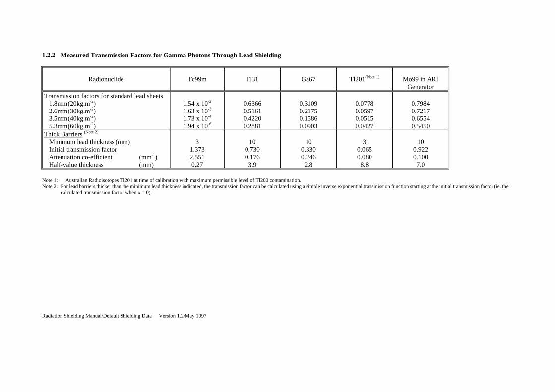
1.2.2 Measured Transmission Factors for Gamma Photons Through Lead Shielding
Radionuclide
Tc99m
I131
Ga67
Tl201(Note 1)
Mo99 in ARI
GeneratorTransmission factors for standard lead sheets 1.8mm (20kg.m-2) 2.6mm (30kg.m-2) 3.5mm (40kg.m-2) 5.3mm (60kg.m-2)
1.54 x 10⁻²
1.63 x 10⁻³
1.73 x 10⁻⁴
1.94 x 10⁻⁶
0.6366 0.5161 0.4220 0.2881
0.3109 0.2175 0.1586 0.0903
0.0778 0.0597 0.0515 0.0427
0.7984 0.7217 0.6554 0.5450
Thick Barriers (Note 2) Minimum lead thickness (mm) Initial transmission factor Attenuation co-efficient (mm-1) Half-value thickness (mm)
3
1.373 2.551 0.27
10
0.730 0.176 3.9
10
0.330 0.246 2.8
3
0.065 0.080 8.8
10
0.922 0.100 7.0
Note 1: Australian Radioisotopes Tl201 at time of calibration with maximum permissible level of Tl200 contamination. Note 2: For lead barriers thicker than the minimum lead thickness indicated, the transmission factor can be calculated using a simple inverse exponential transmission function starting at the initial transmission factor (ie. the
calculated transmission factor when x = 0).
Radiation Shielding Manual/Default Shielding Data Version 1.2/May 1997
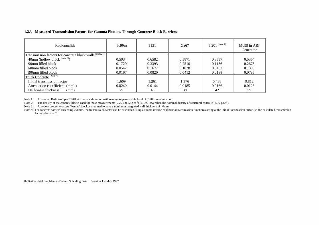
1.2.3 Measured Transmission Factors for Gamma Photons Through Concrete Block Barriers
Radionuclide
Tc99m
I131
Ga67
Tl201 (Note 1)
Mo99 in ARI
GeneratorTransmission factors for concrete block walls (Note2) 40mm (hollow block (Note 3)) 90mm filled block 140mm filled block 190mm filled block
0.5034 0.1729 0.0547 0.0167
0.6582 0.3393 0.1677 0.0820
0.5871 0.2510 0.1028 0.0412
0.3597 0.1186 0.0452 0.0188
0.5364 0.2678 0.1393 0.0736
Thick Concrete (Note 4) Initial transmission factor Attenuation co-efficient (mm-1) Half-value thickness (mm)
1.609
0.0240 29
1.261
0.0144 48
1.376
0.0185 38
0.438
0.0166 42
0.812
0.0126 55
Note 1: Australian Radioisotopes Tl201 at time of calibration with maximum permissible level of Tl200 contamination. Note 2: The density of the concrete blocks used for these measurements (2.29 ± 0.02 g.cc-1) is 3% lower than the nominal density of structural concrete (2.36 g.cc-1). Note 3: A hollow precast concrete "besser" block is assumed to have a minimum integrated wall thickness of 40mm. Note 4: For concrete barriers exceeding 200mm, the transmission factor can be calculated using a simple inverse exponential transmission function starting at the initial transmission factor (ie. the calculated transmission
factor when x = 0).

Radiation Shielding Manual/Default Shielding Data Version 1.2/May 1997
1.2.4 Shielding Parameters for Radionuclides in Lead Storage Containers
Radionuclide
Tc99m I131 Diagnostic
I131 Therapy
Ga67 Tl201 (Note 1) Mo99 in ARI Generator
Thickness of lead storage pot and/or shield (mm) 3.5 7.0 12.5 7.0 3.5 32mm ARI Shield
Normalised dose-equivalent leakage rate from storage pot and/or shield (Sv.m2.GBq-1.hr-1)
4.0 x 10⁻³ 14.2 5.4 1.6 0.84 Door: 8 x 10⁻³ Wall: 12 x 10-3
LEAD SHEETS: Transmission Factors (Note 2) 1.8mm (20kg.m-2) 2.7mm (30kg.m-2) 3.5mm (40kg.m-2) 5.3mm (60kg.m-2)
1.12 x 10⁻² 1.19 x 10⁻³ 1.26 x 10⁻⁴ 1.41 x 10⁻⁶
0.715 0.610 0.523 0.390
0.761 0.668 0.588 0.461
0.626 0.501 0.404 0.268
0.828 0.768 0.714 0.621
0.841 0.771 0.707 0.594
Thick Lead Barrier: (> 4mm lead) Photon fraction Attenuation coefficient (mm-1) Half-value layer (mm)
1.000 2.551 0.27
0.856 0.149
4.7
0.905 0.128 5.4
0.777 0.201
3.4
0.942 0.079
8.8
1.000 0.099
7.0CONCRETE: Transmission Factors (Note 2) 40mm (hollow block (Note 3)) 90mm filled concrete blocks 140mm filled concrete blocks 190mm filled concrete blocks
0.380 0.113 0.034 0.010
0.564 0.275 0.134 0.065
0.562 0.274 0.133 0.065
0.478 0.190 0.075 0.030
0.495 0.214 0.094 0.042
0.604 0.321 0.171 0.091
Thick Concrete Barrier: (>200mm concrete) Photon fraction Attenuation coefficient (mm-1) Half-value layer (mm)
1.00
0.0242 29
1.00
0.0144 48
1.00
0.0144 48
1.00
0.0185 37
0.90
0.0162 43
1.00
0.0126 55
Note 1: Australian Radioisotopes Tl201 at time of calibration with maximum permissible level of Tl200 contamination. Note 2: These transmission factors are for radiation hardened by transmission through the lead walls of the storage pots. Note 3: A hollow precast concrete "Besser" block is assumed to have a minimum integrated wall thickness of 40mm.

Radiation Shielding Manual/Default Shielding Data Version 1.2/May 1997
1.2.5 Shielding Design Parameters for Radioactive Patients
Room
Injection Room
Waiting Room
Camera Room
Mean patient loading and activity for each room
for each camera/week: 60 x 800MBq Tc99m 1 x 300MBq Ga67 5 x 120GBq Tl201
2 patients/camera, each with: 700MBq Tc99m 4MBq Ga67 10MBq Tl201
1 patient/camera, each with: 600MBq Tc99m 4MBq Ga67 10MBq Tl201
Occupancy factors for room 5 minutes/patient 8 hours/day 8 hours/day
Integrated weekly radiation dose from each patient in room (normalised to 1m)
55 Sv/week (1 patient)
400 Sv/week (for each patient)
350 Sv/week (patient on bed)
LEAD LINED WALLS Transmission Factor 20kg.m-2 (1.76mm) lead sheet 0.0182 30kg.m-2 (2.64mm) lead sheet 0.0038 40kg.m-2 (3.52mm) lead sheet 0.0019 60kg.m-2 (5.28mm) lead sheet 0.0012
CONCRETE WALLS Transmission Factor 40mm (unfilled block) 0.3800 100mm concrete block 0.1381 150mm concrete block 0.0435 200mm concrete block 0.0134
Note 1: Typical activities and dose rates for a facility with a single dual-head gamma camera (scale the radiation dose rates as appropriate for other systems).

Radiation Shielding Manual/Default Shielding Data Version 1.2/May 1997
Item 1.3 Therapy X-ray Applications Table 1.3.1 Linear Accelerator
X-ray Equipment Type
Max. Tube Voltage, V (MV)
Max. Workload, W (Gy/wk)
Max. X-ray Leakage (mGy/h @ 1m)
Radiation Beam Use Factor, U
Source to Skin Distance, SSD (m)
Max. Field Size
(cm2)
Range of Collimation Rotation
Walls
Floor Roof
Linear Accelerators
10 1000 10 0.25 1 0.25 1 1600 ±1850
6 1000 10 0.25 1 0.25 1 1600 ±1850
1.3.2 Superficial Therapy
X-ray Equipment Type
Max. Tube Voltage, V (kVp)
Max. Workload, W (mA.min/wk)
Max. Tube Current, I (mA)
Radiation Beam Use Factor, U
Source to Skin Distance, FFD (m)
Max. Field Size
(cm2)
Walls Floor Roof

Radiation Shielding Manual/Default Shielding Data Version 1.2/May 1997
Superficial Therapy
150 300 13 0.25 1.0 0.25 0.30 0.10
20 x 20 10 x 10
Table 1.3.3 Deep Therapy
X-ray Equipment Type
Max. Tube Voltage, V (kVp)
Max. Workload, W (mA.min/wk)
Max. Tube Current, I (mA)
Radiation Beam Use Factor, U
Source to Skin Distance, FFD (m)
Max. Field Size
(cm2)
Walls
Floor Roof
Deep Therapy 300 Data not available
General Note 1. Design parameters specific to the equipment/facility should be used for simulators, CT scanners, fluoroscopy and other X-ray equipment solely used for therapeutic
applications.

Radiation Shielding Manual/Default Shielding Data Version 1.2/May 1997

Radiation Shielding Manual/Default Shielding Data Version 1.0/Draft 3/July 96
1
Appendix 2 Reference Documents
The reference documents provide design principles, computational methods and data for the design of radiation shielding. Details on construction and installation of radiation shielding are also provided. These are the only references currently approved for use. This reference list will be continually reviewed, and amended, where necessary.

Radiation Shielding Manual/Reference Documents Version 1.2/May 1997
REFERENCE DOCUMENTS 2.1 Documents Describing Methods Simpkin D, A General Solution to the Shielding of Medical X and Rays by the NCRP Report No. 49
Methods, Health Physics, Vol. 52, No. 4, pp 431-436, 1987. McGuire LE, A Revised Schema For Performing Diagnostic X-Ray Shielding Calculations, Health
Physics, Vol. 50, No. 1, pp 99-105, 1986. Yaffe MJ, Mawdsley GE, Lilley M, Servant R and Reh G, Composite Material for X-Ray Protection,
Health Physics, Vol. 60, No. 5, pp 661-664, 1991. Shleien B and Terpilak MS, Ed., Health Physics and Radiological Handbook Supplement 1, Nucleon
Lectern Associates Inc., 1986.
Bernard Shleien, Health Physics and Radiological Health Handbook, Revised Edition. Protection Against Ionizing Radiation From External Sources Used in Medicine, ICRP Publication 33,
Annals of ICRP Vol. 9, No. 1, 1982. Radiation Protection Guidelines for 0.1 - 100MeV Particle Accelerator Facilities, NCRP Report 51. Radiation Protection in Radiotherapy, IPSM Report No. 46, Institute of Physical Science in Medicine,
1986. Orhan H Suleiman, Burton J Conway, Thomas R Fewell, Robert J Slayton, Fred G Rueter, Joel Gray,
Radiation Protection Requirements for Medical X-Ray Film, Medical Physics, Vol. 22, No. 10, pp 1691 - 1693, 1995.
Swanson WP, Radiological Safety Aspects of the Operation of Electron Linear Accelerators, IAEA
Report Series 188, Vienna. Simpkin D, Radiation Shielding of Multiple X-Ray Sources in Diagnostic Radiology, Health Physics, Vol.
50, No. 1, pp 117-122, 1986. Simpkin D, Shielding a Spectrum of Workloads in Diagnostic Radiology, Health Physics, Vol. 61, No. 2,
pp 259-261, 1991. Structural Shielding Design and Evaluation for Medical Use of X-rays and Gamma Rays of Energies up
to 10MeV, NCRP Report 49, 1976. Monsour PA, Craggier BJ and Barnes M, X-Ray Equipment Used by General Dental Practioners in
Australia, Australian Dental Journal, Vol. 33, No. 2, pp 81-86, 1988. 2.2 Documents Describing Data Approval and Test Specification - Medical electrical test equipment Part 1 General Requirements for
safety - Collateral Standard: Requirements for radiation protection in diagnostic x-ray equipment, AS/NZS 3200.1 (1996).
Approval and Test Specification Medical Electrical Equipment Particular Standard for Dento-Maxillo
Facial X-Ray Equipment, AS/NZS 3200.2.201 (1996).

Radiation Shielding Manual/Reference Documents Version 1.2/May 1997
Christensen RC, Attenuation Characteristics of Gypsum Wallboard, Health Physics, Vol. 36, pp 595-600, 1979.
Benjamin R Archer, Thomas R Fewell, Burton J Conway and PW Quinn, Attenuation Properties of
Diagnostic X-Ray Shielding Materials, Medical Physics, Vol. 21, No. 9, pp 1499 - 1507, 1994. Rawlings DJ, Faulkner K and Harrison RM, Broad-Beam Transmission Data in Lead For Scattered
Radiation Produced at Diagnostic Energies, The British Journal of Radiology, 64, pp 69-71, 1991. Raymond Rossi, Russell Ritenour and Emmanuel Christodoulou, Broad Beam Transmission Properties
of some common shielding materials for use in Diagnostic Radiology, Health Physics Vol 61, No. 5, pp 601-608, 1991.
Groth MJ, Empirical Dose Rate and Attenuation Data for Radionuclides in Nuclear Medicine, ACPSEM,
Vol. 119, No. 3, pp 160 - 167. Simpkin DJ, Evaluation of NCRP Report No. 48 Assumptions on Workloads and Use Factors in
Diagnostic Radiology Facilities, Medical Physics, Vol. 23, pp 577 - 584, 1996. Simpkin D, Fitting Parameters for Medical Diagnostic X-Ray Transmission Data, Health Physics, Vol.
54, No. 3, pp 345-347, 1988. Robinson A, Notes on Building Materials and References on Shielding Data for Use Below 300 kVp, The
Hospital Physicist's Association, London, 1984. Robert L Dixon, On the Primary Barrier in Diagnostic X-Ray Shielding, Medical Physics, Vol. 21, No. 11,
pp 1785 - 1793, 1994. Banerjee K and Kroher JS Ed., Room Design and Radiation Protection Surveys for Diagnostic and
Orthovoltage X-Ray Units, CRC Handbook of Medical Physics, Vol. 11. Case M, Technical Note: Room Shielding Requirements in Diagnostic Radiology, The British Journal of
Radiology, 67, pp 296-298, 1994. Johnson CH and Walker, Technical Note: The Measurement of Mammographic Room Protection, The
British Journal of Radiology, 67, pp 494-496, 1994. Simpkin D, Transmission Data for Shielding Diagnostic X-Ray Facilities, Health Physics, Vol. 68, No. 5,
pp 704-709, 1995. Glaze SA, Schneiders NJ and Bushong SC, Use of Gypsum Wallboard for Diagnostic X-Ray Protective
Barriers, Health Physics, Vol. 36, pp 587-593, 1979. 2.3 Documents Describing Construction and Inspection of Radiation Shielding Swanson WP, Radiological Safety Aspects of the Operation of Electron Linear Accelerators, IAEA
Report Series 188, Vienna. Structural Shielding Design and Evaluation for Medical Use of X-rays and Gamma Rays of Energies up
to 10MeV, NCRP Report 49, 1976. 2.4 Miscellaneous Documents Metzger R, Richardson R and Van Riper KA, A Monte Carlo Model for Retrospective Analysis of Shield

Radiation Shielding Manual/Reference Documents Version 1.2/May 1997
Design in a Diagnostic X-Ray Room, Health Physics, Vol. 65, No. 2, pp 164-171, 1993. McLean D, Computer Simulation of Broad-Beam and Narrow-Beam Attenuation in Lead for Diagnostic
X-Ray Energies, Medical Physics, Vol. 20, No. 5, pp 1549-1554, 1993.
Archer BR, Thornby JL and Bushong SC, Diagnostic X-Ray Shielding Design Based On an Empirical
Model of Photon Attenuation, Health Physics, Vol. 44, No. 5, pp 507-517, 1983. Nickoloff EL and Berman HL, Factors Affecting X-Ray Spectra, Radiographics, Vol. 13, No. 6, pp
1337-1348, 1993. Raghavendran CP, Nagarajan PS and Venkataraman G, Shielding Calculations Below 100 kVp, Health
Physics, Vol. 42, No. 5, pp 717-723, 1982. Simpkin D, Shielding Requirements for Constant-Potential Diagnostic X-ray Beams Determined by a
Monte Carlo Calculation, Health Physics, Vol. 56, No. 2, pp 151-164, 1989.
Amman E, X-Ray Tubes and Generators for Interventional Radiology, Physics in Diagnostic Radiology, The Institute of Physical Sciences in Medicine, York, pp 64-71.
2.5 Bibliography Johnson DW and Goetz WA, Patient Exposure Trends in Medical and Dental Radiography, Health
Physics, Vol. 50, No. 1, pp 107-116, 1986. Protection against Neutron Radiation, NCRP Report 38, 1971. 1990 Recommendations of the International Commission on Radiological Protection, ICRP Publication
60, Annals of the ICRP 21, Vol 1-3, 1990. Recommendations for Limiting Exposure to Ionizing Radiation (1995) and National Standard for
Limiting Occupational Exposure to Ionizing Radiation, Radiation Health Series No. 39.

Radiation Shielding Manual/Design Report Example Version 1.2/May 1997
1
Appendix 3 Example of a Design Report

Radiation Shielding Manual/Design Report Example Version 1.2/May 1997
DESIGN REPORT (Example Only) 1. Owner: Dr K Health 2. Radiation Facility Address: General X-ray Room
Room No 2, Level A Block 12, Royal Hospital Pacific Highway, Brisbane Q 4000
3. Proposed Use of Facility: Fluoroscopy and Radiography 4. Radiation Apparatus Phillips Medico 30CP Details: 150kVp (max)
One X-ray Table Floor/Ceiling X-ray Tube Stand Wall Mounted Vertical Bucky Stand
5. Design Parameters Workload: 1600mAmin per week Workload Derivation: 400mAmin per week based on 1200 exposures at an average of
20mAs.
1200mAmin per week based on 190 minutes per week screening time at an average screening current of 6mA.
Screening time of 190 minutes was calculated as follows:
1. Pacemaker implants and replacements
15 patients at 2 minutes screening time per patient
2. Electrophysiology studies 5 patients at 2 minutes screening time per patient
3. Radiofrequency ablations
5 patients at 30 minutes screening time per patient Total screening time is equal to 190 minutes per week
Max kVp: 150 Max Continuous Current: 5mA Max Tube Leakage: 1mGy/hr at 1m
Input Field Size: 1st focus: 720cm2
2nd focus: 1500cm2
Focus Skin Distance: 1st focus: 0.80m 2nd focus: 1.6m

Radiation Shielding Manual/Design Report Example Version 1.2/May 1997
6. Conditions of Design
a. The facility is a single story building with no occupiable areas above or below the facility.
b. The position and orientation of the X-ray equipment, bucky and table shall be as shown
in the working plans.
c. The defined use of all associated areas shall not change.
d. The primary beam shall be directed only on wall A, B & C and the floor.
e. The workload shall not increase above 1600mAmin/wk.
f. Unexposed films to be stored in the dark room in a box shielded with 10kg/m2.
g. The controlled areas shall not change. 7. Details of Recommended Shielding
Wall Use factor Shielding Material and Specifications
Preferred Minimum
A 0.25 lead 30 kg/m2 lead 28 kg/m2
B 0.0625 lead 25 kg/m2 lead 23 kg/m2
C 0.25 lead 25 kg/m2 lead 25 kg/m2
D 0 lead 15 kg/m2 lead 13 kg/m2
Film lead 10 kg/m2 lead 10 kg/m2
Floor 1 shielding not required
Ceiling 1 250mm concrete slab 230mm concrete slab
Control 0 lead 25 kg/m2 lead 22 kg/m2
8. Methodologies Used in the Design of Radiation Shielding
a. Structural Shielding Design and Evaluation for Medical Use of X-rays and Gamma Rays of Energies up to 10MeV, NCRP Report 49, 1976.
b. Approval and Test Specification - Medical electrical test equipment Part 1 General
Requirements for safety - Collateral Standard: Requirements for radiation protection in diagnostic x-ray equipment, AS/NZS 3200.1 (1996).
c. Raymond Rossi, Russell Ritenour and Emmanuel Christodoulou, Broad Beam Transmission Properties of some

Radiation Shielding Manual/Design Report Example Version 1.2/May 1997
common shielding materials for use in Diagnostic Radiology, Health Physics, Vol 61, No. 5, pp 601-608, 1991.
d. Amman E, X-Ray Tubes and Generators for Interventional Radiology, Physics in Diagnostic Radiology, The Institute of Physical Sciences in Medicine, York, pp. 64-71.
9. Critical Locations Recommended for Inspection of Radiation shielding
Persons undertaking the inspection of radiation shielding must confirm that shielding to be installed or installed complies with specifications of the design. Shielding in door jambs, overlap of lead sheets and other material, shielding behind switches, locks and other conduits must be verified. Special attention should be given to the following locations in the radiation shielding:
a. Wall A behind the bucky
b. Control panel
c. Wall B - 1m from corner of wall A and wall B (protection to the physiotherapy room)
d. Wall C - 1m from corner of wall C and wall D (protection to dark room)
10. Consultant Details Name: Mr H Smith
17 Queens Drive, Kingsley.
Phone No: (07) 5536 2560
Signature:
Date :

Radiation Shielding Manual/Shielding Plan Example Version 1.2/May 1997
1
Appendix 4 Example of a Shielding Plan Note: This is an example only. One or more radiation facilities may be included on a shielding plan.

Radiation Shielding Manual/Shielding Plan Example Version 1.2/May 1997
Appendix 5 Classification of Radiation Facilities

Radiation Shielding Manual/Classification Version 1.2/May 1997
CLASSIFICATION OF RADIATION FACILITIES As a general guide medical radiation facilities have been categorised into three groups which represent the relative public health risk if appropriate shielding is not installed. (i) Category I (low public health risk) Veterinary Radiography Mammography
Conventional Dental Radiography Bone Densitometry Blood Irradiation (some)
(ii) Category II (medium public health risk)
General Radiography CT Scanning Theatres / Screening Rooms Dental Panoramic Tomography Tomography Blood Irradiation (some) Nuclear Medicine (Medical and Veterinary) Chiropractic Radiography Superficial Therapy
(iii) Category III (high public health risk)
Cardiac Theatres Radiation Therapy (linear accelerators) Radiotherapy (using sealed and unsealed radioactive substances including remote after loading devices)

Radiation Shielding Manual/Forms Version 1.2 /May 1997
1
Appendix 6 Notification Forms

Radiation Shielding Manual/Acknowledgment Version 1.2/May 1997
1
Appendix 7 Acknowledgment

Radiation Shielding Manual/Acknowledgment Version 1.2/May 1997
ACKNOWLEDGMENT The content of this document is the end product of a lengthy consultation and discussion process. The persons involved in this are as follows:
Mr S Carter Mr P Christiansen
Mr S Critchley Dr B Mason Ms U Rajappa Dr L Sim Dr D Thiele Ms P Veevers
Dr D Waggett Mr B Wallace

Radiation Shielding Manual/Acknowledgment Version 1.2/May 1997

MEDICAL RADIATION APPARATUS
Notification of Construction of Radiation Shielding Details of only one radiation apparatus should be included on this form. Please photocopy this form if you need to include details of more than one apparatus.
Radiation Shielding Manual/Acknowledgment Version 1.2/May 1997
1
LICENSEE / OWNER DETAILS
Corporate name / Registered company name & ACN Name of licensee / owner Address (for correspondence only) Contact telephone number Contact
facsimile number
CERTIFICATION
DETAILS 1. CERTIFICATION FROM THE LICENSEE I certify that the radiation apparatus will operate in compliance with design parameters and conditions of design as specified by the radiation shielding consultant. I also understand that any deviation from the conditions of the design or design parameters will invalidate the radiation shielding design and necessitate a review of the radiation shielding. Signature of owner / licensee Date 2. CERTIFICATION OF THE RADIATION SHIELDING DESIGN Name of radiation shielding consultant Address (for correspondence only) Contact telephone number Qld Health Accreditation Number I certify that the radiation shielding design has been prepared using methodologies approved in the Queensland Health Radiation Shielding Manual and shielding recommended by me will limit the doses to all areas to below the Design Limits established by the Chief Health Officer. Signature of Consultant Date 3. CERTIFICATION OF CONSTRUCTION OF RADIATION
SHIELDING Name of radiation shielding consultant Address (for correspondence only) Contact telephone number Qld Health Accreditation Number
I certify that the radiation facility has been constructed to conform to the radiation shielding design specified herein and I have verified the integrity of the radiation shielding installed using the following method approved in the Queensland Health Radiation Shielding Manual (please tick appropriate response).
Visual Inspection Non Destructive Testing Destructive Testing Radiation Dose Survey
Signature of Consultant Date

MEDICAL RADIATION APPARATUS
Notification of Construction of Radiation Shielding Details of only one radiation apparatus should be included on this form. Please photocopy this form if you need to include details of more than one apparatus.
APPLICATION ENQUIRIES TO: The Chief Health Officer, 450 Gregory Tce, Fortitude Valley, 4006 Telephone: (07) 3406 8000 Facsimile: (07) 3406 8030
Action Required - 2
Corrective Action By Date:
Audit Number 2 Date:
Physicist
Compliance Notice #
Corrective Action By Date:
REASON FOR THIS APPLICATION New Radiation Facility (indicate whether new or existing premise) Alterations to a Registered Facility (indicate the alterations/additions made)
RADIATION FACILITY DETAILS Type of Radiation Facility (eg Mammography Room, Theatre, General X-Ray Room etc) Address (location of the apparatus within the address, eg Room 1, Floor 2, B Block, Smith Hospital, Smithfield)
RADIATION APPARATUS DETAILS Manufacturer Max mA Model Max kVp
DESIGN PARAMETER DETAILS Max kVp Max mA Max Leakage Workload
CONDITIONS OF DESIGN (eg fluoroscopy unit is dedicated to fluoroscopic functions only, ie no primary projections)
1
2
3 4 5 6 7
INSTALLED SHIELDING DETAILS (please reference the shielding details to the attached working plan)
Barrier Use
Factor Shielding Installed eg. Lead 10kg/m2
Barrier Use Factor
Shieldeg. Le
Wall Wall Wall Door Wall Door Wall Window
µGy/hr at 1m mAmin/wk
mAmin/wk
mAmin/wk mAmin . m

MEDICAL RADIATION APPARATUS
Notification of Construction of Radiation Shielding Details of only one radiation apparatus should be included on this form. Please photocopy this form if you need to include details of more than one apparatus.
2
Wall Window Wall Ceiling Wall Floor Wall Viewing Panel Wall Film Hopper
Radiation Health Audit (Radiation Health Use Only)
attach separate sheet for details on non-compliance
Audit Details
Audit Checks
Audit 1
Audit 2
Facility Details
Address
Location
Radiation Apparatus
Manufacturer
Model
Serial Number
Design Parameters
Workload
Max kVp
Max mA
Leakage
Occupancy
Use Factors
Isodose Curves
LICENSEE / OWNER DETAILS Corporate name / Registered company name & ACN
Name of licensee / owner Address (for correspondence only) Contact telephone number Contact

SEALED AND UNSEALED SOURCES
Notification of Construction of Radiation Shielding
APPLICATION ENQUIRIES TO: The Chief Health Officer, 450 Gregory Tce, Fortitude Valley, 4006 Telephone (07) 3406 8000 Facsimile (07) 3406 8030
facsimile number
CERTIFICATION DETAILS 1. CERTIFICATION FROM THE LICENSEE I certify that the radiation facility will operate in compliance with design parameters and conditions of design as specified by the radiation shielding consultant. I also understand that any deviation from the conditions of the design or design parameters will invalidate the radiation shielding design and necessitate a review of the radiation shielding. Signature of owner / licensee Date 2. CERTIFICATION OF THE RADIATION SHIELDING DESIGN Name of radiation shielding consultant Address (for correspondence only) Contact telephone number Qld Health Accreditation Number I certify that the radiation shielding design has been prepared using methodologies approved in the Queensland Health Radiation Shielding Manual and shielding recommended by me will limit the doses to all areas to below the Design Limits established by the Chief Health Officer. Signature of Consultant Date 3. CERTIFICATION OF CONSTRUCTION OF RADIATION
SHIELDING Name of radiation shielding consultant Address (for correspondence only) Contact telephone number Qld Health Accreditation Number I certify that the radiation facility has been constructed to conform to the radiation shielding design specified herein and I have verified the integrity of the radiation shielding installed using the following method approved in the Queensland Health Radiation Shielding Manual (please tick appropriate response).
Visual Inspection Non Destructive Testing Destructive Testing Radiation Dose Survey
Signature of Consultant Date

SEALED AND UNSEALED SOURCES
Notification of Construction of Radiation Shielding
APPLICATION ENQUIRIES TO: The Chief Health Officer, 450 Gregory Tce, Fortitude Valley, 4006 Telephone (07) 3406 8000 Facsimile (07) 3406 8030
Compliance Notice #
Improvement Notice #
Action Required - 1
Corrective Action By Date:
REASON FOR THIS APPLICATION
New Radiation Facility (indicate whether new or existing premises)
Alterations to a Registered Facility (indicate the alterations / additions made)
RADIATION FACILITY DETAILS Type of Radiation Facility (eg Nuclear Medicine Facility, Pathology etc.) Address (location of the apparatus within the address, eg Room 1, Floor 2, B Block, Smith Hospital, Smithfield) RADIATION SOURCE DETAILS
No. Isotope (sealed/ unsealed)
Activity Local Shielding No. Isotope (sealed/ unsealed)
Activity Local Shielding
CONDITIONS OF DESIGN (eg the Mo99 generator shall be stored within the ARI shield)
1 2
3 4 5 6 7
INSTALLED SHIELDING DETAILS (please reference the shielding details to the attached working plan)
Barrier Use
Factor Shielding Installed eg. Lead 10kg/m2
Barrier Use Factor
Sheg
Wall Door Wall Door Wall Window Wall Window Wall Ceiling Wall Floor Wall Viewing Panel

SEALED AND UNSEALED SOURCES
Notification of Construction of Radiation Shielding
APPLICATION ENQUIRIES TO: The Chief Health Officer, 450 Gregory Tce, Fortitude Valley, 4006 Telephone (07) 3406 8000 Facsimile (07) 3406 8030
Radiation Source
Mo99 Generator
Unsealed Sources
Gamma Camera No.
Design Parameters
Max Activities
Local shielding
Waste
Used Generators
Occupancy
Storage
Sealed Sources
Working Plan Details
Position (of Sources)
Hot Lab
Patient Waiting
Injection Room
Gamma Camera Room
Patient Toilet
Layout
Used Generator Store
Controlled Areas
Other Radiation Sources
Report
Design Report
Conditions of Design
Shielding Details
Installation
Height